EP3312480A1 - Dichtung und dichtungsanordnung - Google Patents
Dichtung und dichtungsanordnung Download PDFInfo
- Publication number
- EP3312480A1 EP3312480A1 EP17193214.8A EP17193214A EP3312480A1 EP 3312480 A1 EP3312480 A1 EP 3312480A1 EP 17193214 A EP17193214 A EP 17193214A EP 3312480 A1 EP3312480 A1 EP 3312480A1
- Authority
- EP
- European Patent Office
- Prior art keywords
- seal
- sealing arrangement
- sealing
- housing
- machine element
- Prior art date
- Legal status (The legal status is an assumption and is not a legal conclusion. Google has not performed a legal analysis and makes no representation as to the accuracy of the status listed.)
- Granted
Links
Images




Classifications
-
- F—MECHANICAL ENGINEERING; LIGHTING; HEATING; WEAPONS; BLASTING
- F16—ENGINEERING ELEMENTS AND UNITS; GENERAL MEASURES FOR PRODUCING AND MAINTAINING EFFECTIVE FUNCTIONING OF MACHINES OR INSTALLATIONS; THERMAL INSULATION IN GENERAL
- F16J—PISTONS; CYLINDERS; SEALINGS
- F16J15/00—Sealings
- F16J15/16—Sealings between relatively-moving surfaces
- F16J15/34—Sealings between relatively-moving surfaces with slip-ring pressed against a more or less radial face on one member
- F16J15/3492—Sealings between relatively-moving surfaces with slip-ring pressed against a more or less radial face on one member with monitoring or measuring means associated with the seal
-
- F—MECHANICAL ENGINEERING; LIGHTING; HEATING; WEAPONS; BLASTING
- F16—ENGINEERING ELEMENTS AND UNITS; GENERAL MEASURES FOR PRODUCING AND MAINTAINING EFFECTIVE FUNCTIONING OF MACHINES OR INSTALLATIONS; THERMAL INSULATION IN GENERAL
- F16J—PISTONS; CYLINDERS; SEALINGS
- F16J15/00—Sealings
- F16J15/16—Sealings between relatively-moving surfaces
- F16J15/32—Sealings between relatively-moving surfaces with elastic sealings, e.g. O-rings
- F16J15/3296—Arrangements for monitoring the condition or operation of elastic sealings; Arrangements for control of elastic sealings, e.g. of their geometry or stiffness
-
- F—MECHANICAL ENGINEERING; LIGHTING; HEATING; WEAPONS; BLASTING
- F16—ENGINEERING ELEMENTS AND UNITS; GENERAL MEASURES FOR PRODUCING AND MAINTAINING EFFECTIVE FUNCTIONING OF MACHINES OR INSTALLATIONS; THERMAL INSULATION IN GENERAL
- F16J—PISTONS; CYLINDERS; SEALINGS
- F16J15/00—Sealings
- F16J15/02—Sealings between relatively-stationary surfaces
- F16J15/06—Sealings between relatively-stationary surfaces with solid packing compressed between sealing surfaces
- F16J15/064—Sealings between relatively-stationary surfaces with solid packing compressed between sealing surfaces the packing combining the sealing function with other functions
-
- F—MECHANICAL ENGINEERING; LIGHTING; HEATING; WEAPONS; BLASTING
- F16—ENGINEERING ELEMENTS AND UNITS; GENERAL MEASURES FOR PRODUCING AND MAINTAINING EFFECTIVE FUNCTIONING OF MACHINES OR INSTALLATIONS; THERMAL INSULATION IN GENERAL
- F16J—PISTONS; CYLINDERS; SEALINGS
- F16J15/00—Sealings
- F16J15/16—Sealings between relatively-moving surfaces
- F16J15/32—Sealings between relatively-moving surfaces with elastic sealings, e.g. O-rings
- F16J15/3204—Sealings between relatively-moving surfaces with elastic sealings, e.g. O-rings with at least one lip
- F16J15/3232—Sealings between relatively-moving surfaces with elastic sealings, e.g. O-rings with at least one lip having two or more lips
-
- F—MECHANICAL ENGINEERING; LIGHTING; HEATING; WEAPONS; BLASTING
- F16—ENGINEERING ELEMENTS AND UNITS; GENERAL MEASURES FOR PRODUCING AND MAINTAINING EFFECTIVE FUNCTIONING OF MACHINES OR INSTALLATIONS; THERMAL INSULATION IN GENERAL
- F16J—PISTONS; CYLINDERS; SEALINGS
- F16J15/00—Sealings
- F16J15/16—Sealings between relatively-moving surfaces
- F16J15/32—Sealings between relatively-moving surfaces with elastic sealings, e.g. O-rings
- F16J15/3248—Sealings between relatively-moving surfaces with elastic sealings, e.g. O-rings provided with casings or supports
- F16J15/3252—Sealings between relatively-moving surfaces with elastic sealings, e.g. O-rings provided with casings or supports with rigid casings or supports
-
- F—MECHANICAL ENGINEERING; LIGHTING; HEATING; WEAPONS; BLASTING
- F16—ENGINEERING ELEMENTS AND UNITS; GENERAL MEASURES FOR PRODUCING AND MAINTAINING EFFECTIVE FUNCTIONING OF MACHINES OR INSTALLATIONS; THERMAL INSULATION IN GENERAL
- F16J—PISTONS; CYLINDERS; SEALINGS
- F16J15/00—Sealings
- F16J15/16—Sealings between relatively-moving surfaces
- F16J15/32—Sealings between relatively-moving surfaces with elastic sealings, e.g. O-rings
- F16J15/3284—Sealings between relatively-moving surfaces with elastic sealings, e.g. O-rings characterised by their structure; Selection of materials
-
- G—PHYSICS
- G01—MEASURING; TESTING
- G01M—TESTING STATIC OR DYNAMIC BALANCE OF MACHINES OR STRUCTURES; TESTING OF STRUCTURES OR APPARATUS, NOT OTHERWISE PROVIDED FOR
- G01M13/00—Testing of machine parts
- G01M13/005—Sealing rings
-
- F—MECHANICAL ENGINEERING; LIGHTING; HEATING; WEAPONS; BLASTING
- F16—ENGINEERING ELEMENTS AND UNITS; GENERAL MEASURES FOR PRODUCING AND MAINTAINING EFFECTIVE FUNCTIONING OF MACHINES OR INSTALLATIONS; THERMAL INSULATION IN GENERAL
- F16J—PISTONS; CYLINDERS; SEALINGS
- F16J15/00—Sealings
- F16J15/16—Sealings between relatively-moving surfaces
- F16J15/32—Sealings between relatively-moving surfaces with elastic sealings, e.g. O-rings
- F16J15/3204—Sealings between relatively-moving surfaces with elastic sealings, e.g. O-rings with at least one lip
Definitions
- the invention relates to a seal having at least one sealing lip for sealing the gap between a machine element and a housing, comprising a base body made of elastic material.
- the invention further relates to a sealing arrangement for sealing a gap between a machine element and a housing, comprising at least one seal.
- the invention also relates to a method for monitoring a seal arrangement.
- Gaskets in particular dynamically stressed gaskets wear off during the anticipated service life, with various wear phenomena coming to fruition. Due to material fatigue, the contact stress of the seal decreases, as does the contact pressure. Due to wear and setting behavior, the dimensions of the seal change. These processes lead to a leakage first and then a failure of the sealing system.
- the sealing element comprises an electrically conductive portion and an electrically non-conductive portion, which is in contact with the machine element to be sealed.
- the machine element is also electrically conductive. Due to wear of the sealing element, the electrically non-conductive sealing material wears off, so that the electrically conductive sealing material comes into contact with the machine element. This closes a circuit and it can be determined that the sealing element is worn. In this embodiment, it is disadvantageous that no gradual state changes can be detected. It can only be determined that the wear limit has been reached and that the sealing element must be replaced.
- the invention has for its object to provide a seal and a seal assembly, which allows a permanent condition monitoring of the seal. Also, a condition monitoring procedure shall be described.
- the cover follows the outer contour of the body.
- the cover has a relatively small thickness and lies flat against the base body.
- the measuring principle is based on the fact that an electrical voltage is applied between the base body of the seal and the machine element or between the base body of the seal and housing and the capacitance between the components is determined.
- Significant influencing factors of the electrical capacitance are the dielectric constant of the insulating medium, which in the present case is the cover, as well as the area of the main body relative to the machine element and the distance between the machine element and the main body.
- the transmitter may include a capacitance meter, a memory, and an output, such as lamps; Printer or a screen display.
- an output such as lamps; Printer or a screen display.
- the cover may be associated with at least the areas of the body, which are in contact with the machine element and the housing. In this case, the cover can completely surround the main body on the outer peripheral side. In other embodiments, areas of the body can remain uncovered. Conceivable here are in particular the areas facing in the direction of the sealing gap and reach neither in contact with the machine element nor with the housing.
- the cover is preferably bonded cohesively to the body.
- the main body may consist of elastomeric material.
- proven sealing materials such as NR, EPDM, EVM, ECO, CR, NBR, XNBR, ACM, AEM, HNBR, XHNBR, FKM and FFKM as well as blends of these materials are particularly suitable.
- thermoplastic elastomers and thermoplastics as a material for the body is conceivable.
- the cover is preferably made of an elastomer, a thermoplastic material or PTFE.
- a cover formed from an elastomer adheres due to the similar material particularly good cohesive to the body.
- a thermoplastic material can be molded onto the base body in a particularly simple manner by means of injection molding and adheres to the base body in a material-locking manner.
- An adhesion can also be produced by a positive connection. In this context, it is particularly conceivable to form the connection by mechanical engagement by means of a geometric shape of the base body. In both cases, however, the liability can also come about through a bonding agent.
- a cover made of PFTE has a particularly low static friction coefficient and a high chemical resistance. Furthermore, a cover consisting of PFTE is particularly wear-resistant.
- a bonding agent is used to bond the topcoat made of PTFE to the base body. Again, a positive connection is conceivable. It is essential in each case that the material of the cover jacket is electrically insulating, while the material of the base body is electrically conductive.
- the elastic material may be provided with electrically conductive particles.
- carbon particles are, for example, conductive carbon blacks, graphites, carbon fibers or carbon nanotubes.
- Metal particles are, for example, stainless steel fibers, metal fibers, metal powders, coated metal powders, such as silver-coated copper flakes.
- the metal particles may also consist of aluminum or iron oxide. Both carbon particles and metal particles are electrically conductive and cause the elastic material of the body as a whole to be electrically conductive.
- the main body may be provided with a contact element for electrical contacting.
- the contact element is preferably designed so that a secure electrical contact of the body is given and that the contact takes place as little resistance as possible.
- the contact element is disc-shaped and rests flat against the base body.
- the contact element preferably comes in the region of the body to the plant, which is associated with the gap between the housing and machine element in the installed state of the seal and neither in contact with the housing nor in contact with the Machine element passes.
- the contact element may be formed in the form of a plate spring.
- a sealing arrangement according to the invention for sealing a gap between a machine element and a housing comprises at least one seal and evaluation electronics for detecting the electrical capacitance between the base body of the seal and the machine element or the housing, ie the capacity of the cover of the seal in the region of the sealing point.
- the transmitter may include a capacitance meter, a memory and an output device, such as a screen display.
- At least the machine element or the housing is electrically conductive according to the invention. Whether the machine element or housing must be electrically conductive depends on whether the seal is attached to the housing or to the machine element. If the seal is attached to the housing, then the machine element must be conductive. If the seal is attached to the machine element, the housing must be conductive. The respective other component can also be conductive. For the condition monitoring of the seal, in particular its wear, an electrical voltage is applied between the machine element or the housing and the base body of the seal, so that the electrical capacitance can be determined. This is detected by the transmitter. In addition, the transmitter can also detect gradual changes in electrical capacity, a so-called drift of capacity. The changes in the electrical capacitance arise e.g. due to dimensional changes due to wear of the cover.
- the degree of change in the capacity can be determined in the transmitter, so the first time derivative of the capacity, and included in the evaluation. For example, a warning may be issued if there is a large increase in capacity.
- the measurement of the capacitance and the conclusion about the condition of the seal, in particular the wear of the seal has the advantage that it can be configured as a relative measurement. That the capacity of a new seal is measured during assembly and a limit is established relative to this measured value of the capacitance at which the wear becomes unduly large. Alternatively, stored limit values can be calibrated depending on the capacity measured for the first time. Because in both cases no absolute limit is given, tolerances in the characteristics of the cover, e.g. the thickness allowed.
- Dielectric spectroscopy is a method of impedance spectroscopy which detects the dielectric properties of a material, here the insulating layer.
- the impedance ie the AC resistance of the material, is determined as a function of the frequency.
- the impedance is a measure of the aging of the material.
- the invention may thus include the possibility of monitoring the dielectric properties of the material by varying the frequency and thereby obtaining more extensive information on the material condition.
- ⁇ is a complex variable and is also called complex permittivity ⁇ *.
- ⁇ * consists of a real and an imaginary part, the real part being called ⁇ 'and denoting the part of the dielectric response which is in phase with the applied field, while ⁇ "represents the imaginary part which is not in Phase is.
- the latter can take place on the one hand in the mesoscale region at internal interfaces (Maxwell / Wagner / Sillars polarization) and / or macroscopically on the contact between sample and outer electrodes.
- the polarization contribution can exceed the effects by molecular mechanisms by several orders of magnitude.
- the applied voltage should be as low as possible, the frequency range is varied.
- the real and imaginary parts of the complex dielectric function are included, in another embodiment the dielectric modulus M can serve as a characteristic quantity. Changes in the measured variables can be clearly assigned structural changes by detailed evaluation with model functions known to the person skilled in the art (eg Cole-Cole, H192iak-Negami).
- the seal assembly may further comprise a support body in an advantageous embodiment, wherein the support body is formed of electrically insulating material.
- the support body is made of thermoplastic material.
- the support body supports on the one hand the main body in the space and on the other hand prevents areas of the body come into contact with the housing and / or the machine element, which are not covered with the cover.
- the support body is preferably provided with a device for electrical connection of the contact element with an evaluation.
- an electrical connection is made on the one hand with the contact elements of the base body, which can be done via a non-positive contact of an electrically conductive portion of the support body and on the other hand with the transmitter.
- the support body may be provided, for example with terminal lugs, which allows easy connection with cable lugs cabling.
- the seal arrangement on two seals which are each assigned to an axial end face of the support body, so that the seal assembly bi-directionally seals.
- a sealing arrangement is particularly advantageous when the seal assembly is a rod seal.
- the housing is, for example, a cylinder housing and the rod is a piston.
- the seal arrangement seals the gap filled with a medium.
- medium depends on the particular application and may include lubricant media such as transmission fluids and hydraulic fluids.
- media of food technology in particular in the field of filling known media such as milk, lemonade, beer and their cleaning media, so-called CIP / SIP cleaning media.
- seal assembly according to the invention with permanent condition monitoring and leakage monitoring is generally advantageous in all dynamic sealing systems with a molded sealing lip.
- seals which have at least one defined sealing lip, as in the case of radial shaft seals.
- the seal can also be designed as a profile seal, flap seal or X-ring.
- the method can be applied analogously.
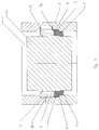
- FIG. 1 shows a seal 1 with a sealing lip 2 for sealing a gap 3 between a machine element 4 and a housing 5.
- the sealing lip 2 bears with radial bias sealingly against the machine element 4.
- the seal 1 is received in a circumferential groove 13 of the housing 5 and fixed in the housing 5 fixed.
- the seal 1 comprises a base body 6 made of elastic material, formed of elastomeric material, in this embodiment of EPDM.
- the base body 6 is equipped with electrically conductive particles in the form of Leitruß electrically conductive.
- the specific electrical volume resistance of the base body 6 equipped with conductive particles, determined according to DIN IEC 60093, is between 1E + 01 ⁇ xcm 2 / cm and 1E + 07 ⁇ xcm 2 / cm.
- An exemplary basic body 6 consisting of EPDM has a volume resistivity of 7.3E +03 ⁇ and a volume resistivity of 7.3E + 05 ⁇ xcm 2 / cm.
- the main body 6 is partially covered on the outside with a cover 7 made of electrically insulating material.
- the cover 7 is made of PTFE and is bonded via a bonding agent cohesively to the base body 6.
- the cover 7 is assigned to the areas of the main body 6, which are in contact with the machine element 4 and the housing 5.
- the thickness of the cover jacket 7 is presently 0.5 mm.
- a section 12 on the axial end face of the main body 6, facing the gap 3, is not covered by the cover 7.
- the cover 7 is formed of a coating, for example in the form of a bonded coating.
- the main body 6 is provided with a contact element 8 for electrical contacting.
- the contact element 8 is shaped in the form of a plate spring and is located on the uncovered by the cover 7 section 12 on the base body 6 at.
- FIG. 2 shows a seal assembly 9 for sealing a gap 3 between a machine element 4 and a housing 5.
- the seal assembly is formed as a rod seal.
- the housing 5 is a cylinder housing and the machine element is a rod, or a piston.
- the sealing arrangement 9 seals the gap 3 filled with a medium.
- the sealing arrangement 9 is presently designed as a bidirectional sealing arrangement 9 and has two seals 1 according to FIG FIG. 1 on, wherein the sealing lips 2 point in opposite axial directions.
- the two seals 1 are supported on a support body 10 arranged in the groove 13.
- the seals 1 are assigned to an axial end face 12 of the support body 10.
- the support body 10 is formed of electrically insulating material.
- the support body 10 is provided with a device 11 for electrical connection of the contact element 8 with an evaluation.
- the device 11 is in electrically conductive connection with the contact element 8 and has radially outwardly projecting connecting elements 14 in the form of contact lugs.
- the machine element 4 and at least part of the housing 5 are electrically conductive, wherein the evaluation electronics detects the electrical capacitance between the main body 6 and the machine element 4 and / or between the main body 6 and the housing 5.
- FIG. 3 shows the seal assembly 9 according to FIG. 2 , In this embodiment, however, only one seal 1 is provided, so that the seal assembly is a monodirectional seal assembly 9. This embodiment is particularly suitable as a radial shaft seal.
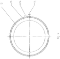
- FIG. 4 shows in detail the support body 10 with the connecting elements 14th
- the seal assembly 9 is a radial shaft seal 1.
- the seal takes place about a rotating shaft.
- the sealing lip 2 may be equipped with a cover 7, which wears off in the course of the life and brings the conductive body 6 to rest on the shaft 4.
- Such a radial shaft seal 1 is in FIG. 5 shown.
- Non-elastomeric sensor body comprising a cover 7 and a base 6 made of non-elastomeric material.
- the sensor body interacts with pressing elements, for example a support O-ring or other elastomeric pressing elements, which effect the contact pressure.
- FIG. 6 the seal is off FIG. 1 represented with a schematically indicated evaluation.
- FIG. 7 is the seal assembly off FIG. 2 represented with a schematically indicated evaluation.
- FIG. 8 shows a seal 1 with a sealing lip 2 for sealing a gap 3 between a machine element 4 and a housing 5.
- the sealing lip 2 is sealingly against the housing 5 at.
- the inner circumference is the seal 1 in a recess of the machine element 4 is received and fixed in the machine element 4 fixed.
- the seal 1 comprises a base body 6 made of elastic material and is equipped with electrically conductive particles.
- the main body 6 is partially covered on the outside with a cover 7 made of electrically insulating material.
- the evaluation electronics 20 comprises a capacitance measuring device 23 with an alternating voltage source U. An alternating voltage U is applied to the sealing arrangement 9 and the capacitance C is determined in the region of the sealing point.
- the evaluation electronics 20 further comprises a memory 21 in which at least one limit value is stored and an output device 22, for example, colored Helemente such as LEDs, a printer or a screen for outputting information.
- Capacitor 23, memory 21 and output device 22 are connected to one another in terms of data transmission technology.
- the output device 22 can also be embodied as a data connection to a server, through which the measured values are prepared and information is sent using generally known communication means such as e-mail, short message or app.
- the information can be used to convey an instruction to a machine operator or machine manager, for example to order a new seal, to replace the seal or, in the case of safety risks, to shut down the machine in which the seal arrangement is used.
- applications known in the context of Industry 4.0 are also possible, such as the automatic ordering of spare parts, the automatic scheduling of maintenance operations, etc.
- the wear over the course of time could be related to other machine data are set, which provides the machine in which the seal assembly is used. Based on such an evaluation, for example, an optimization of the seal arrangement or an adjustment of the operating conditions of the machine could take place.
- FIG. 9 the relationship between the measured in a seal assembly 9 capacitance C and the occurring wear X of a cover shell 7 in the region of a sealing lip 2 of a seal 1 over the course of time t is shown.
- the capacitance C is plotted and in the upper curve, the wear X is plotted. Due to the direct relationship between the capacitance C and the wear X can be concluded by a measured capacitance C on an actual wear X.
- the measurement of the capacitance C can be continuous or quasi-continuous, ie in a fixed cycle. Alternatively, the measurement can be made at certain times ti, which can be determined in advance, depending on the structure and use of the seal and the seal assembly.
- the measured value is adjusted with limit values stored in a memory 21 of the evaluation electronics 20.
- a first limit C1 can be set, which is achieved in the example shown at time t1. After the adjustment, information can be output that due to an already advanced wear X of the seal 1, a new seal 1 should be ordered.
- a new seal 1 can also be ordered directly.
- a second limit value C2 is reached, which corresponds to a critical state of wear X2.
- information may be output that replacement of the seal 1 should be done.
- a repair order can also be initiated directly to a known and named service provider. If no replacement of the seal 1 so at a later time t3 a third limit C3 is reached, to which the wear X has advanced to a highly critical and risky measure. After evaluation of the measured value, information can be output that the sealing arrangement 9 should no longer be operated in this way.
- the evaluation electronics 20 could be switched off for their protection. If safety risks exist during the continued operation of the sealing arrangement 9, then the machine in which the sealing arrangement 9 is used could also be shut down in a controlled manner. Limits C1 and C3 are considered optional. The limit C2 should be present anyway.
Landscapes
- Engineering & Computer Science (AREA)
- General Engineering & Computer Science (AREA)
- Mechanical Engineering (AREA)
- Physics & Mathematics (AREA)
- General Physics & Mathematics (AREA)
- Investigating Or Analyzing Materials By The Use Of Electric Means (AREA)
- Sealing With Elastic Sealing Lips (AREA)
- Measurement Of Length, Angles, Or The Like Using Electric Or Magnetic Means (AREA)
Abstract
Description
- Die Erfindung betrifft eine Dichtung mit zumindest einer Dichtlippe zur Abdichtung des Spalts zwischen einem Maschinenelement und einem Gehäuse, umfassend einen Grundkörper aus elastischem Material. Die Erfindung betrifft ferner eine Dichtungsanordnung zur Abdichtung eines Spalts zwischen einem Maschinenelement und einem Gehäuse, umfassend zumindest eine Dichtung. Die Erfindung betrifft auch ein Verfahren zur Überwachung einer Dichtungsanordnung.
- Dichtungen, insbesondere dynamisch beanspruchte Dichtungen nutzen sich während der vorhergesehenen Lebensdauer ab, wobei verschiedene Abnutzungsphänomene zum Tragen kommen. Durch Materialermüdung lässt die Kontaktspannung der Dichtung nach, ebenso nimmt die Anpresskraft ab. Durch Verschleiß und Setzverhalten ändern sich die Dimensionen der Dichtung. Diese Vorgänge führen dazu, dass es zunächst zu einer Leckage und anschließend zum Ausfall des Dichtsystems kommt.
- Zur Leckage-Überwachung von Dichtungen ist es bekannt, in die Dichtung eine Einrichtung zur Leckage-Überwachung zu integrieren. Aus der
DE 10 2007 007 405 B4 ist eine elektrische Einrichtung zur Erkennung des Verschleißzustandes eines dynamischen Dichtelements bekannt. Das Dichtelement umfasst einen elektrisch leitfähigen Abschnitt und einen elektrisch nicht-leitfähigen Abschnitt, welcher mit dem abzudichtenden Maschinenelement in Kontakt steht. Das Maschinenelement ist ebenfalls elektrisch leitfähig. Durch Verschleiß des Dichtelements nutzt sich das elektrisch nicht-leitende Dichtmaterial ab, so dass das elektrisch leitende Dichtmaterial in Kontakt mit dem Maschinenelement gelangt. Dabei schließt sich ein Stromkreis und es kann ermittelt werden, dass das Dichtelement verschlissen ist. Bei dieser Ausgestaltung ist nachteilig, dass keine allmählichen Zustandsänderungen erfassbar sind. Es kann lediglich ermittelt werden, dass die Verschleißgrenze erreicht ist und dass das Dichtelement ausgetauscht werden muss. - Der Erfindung liegt die Aufgabe zugrunde, eine Dichtung und eine Dichtungsanordnung bereitzustellen, welche eine permanente Zustandsüberwachung der Dichtung ermöglicht. Auch soll ein Verfahren zur Zustandsüberwachung beschrieben werden.
- Diese Aufgabe wird mit den Merkmalen von Anspruch 1 gelöst. Auf vorteilhafte Ausgestaltungen nehmen die Unteransprüche Bezug.
- Zur Lösung der Aufgabe ist der Grundkörper der Dichtung elektrisch leitfähig ausgerüstet und außenseitig zumindest teilweise mit einem Deckmantel aus elektrisch isolierendem Material bedeckt. Dabei folgt der Deckmantel der Außenkontur des Grundkörpers. Der Deckmantel weist dabei eine verhältnismäßig geringe Dicke auf und liegt flächig an dem Grundkörper an. Das Messprinzip beruht darauf, dass zwischen Grundkörper der Dichtung und Maschinenelement oder zwischen Grundkörper der Dichtung und Gehäuse eine elektrische Spannung angelegt wird und die Kapazität zwischen den Bauelementen bestimmt wird. Wesentliche Einflussgrößen der elektrischen Kapazität sind die Elektrizitätskonstante des isolierenden Mediums, welches vorliegend der Deckmantel ist, sowie die Fläche des Grundkörpers relativ zu dem Maschinenelement und der Abstand zwischen Maschinenelement und Grundkörper. Ändert sich durch zunehmenden Verschleiß die Dicke des Deckmantels, ändert sich somit auch die elektrische Kapazität zwischen diesen Elementen, was durch eine geeignete Auswerteelektronik erfasst werden kann. Die Auswerteelektronik kann ein Kapazitätsmessgerät, einen Speicher und eine Ausgabe, beispielsweise Lampen; Drucker oder eine Bildschirmanzeige aufweisen. Durch eine solche Ausgestaltung sind auch allmähliche Veränderungen und allmählicher Verschleiß erfassbar. Dies ermöglicht eine permanente Zustandsüberwachung der Dichtung, der Dichtungsanordnung und der Dichtfunktion. Auf Grund der permanenten Zustandsüberwachung kann rechtzeitig vor einem Ausfall der Dichtung gewarnt und eine Leckage der Dichtungsanordnung so vermieden werden. Die erfindungsgemäße Ausgestaltung einer Dichtung ist für alle Dichtsysteme anwendbar, die durch eine dynamische Beanspruchung einem Verschleiß unterliegen. Diese Erfindung ist auch vorteilhaft gegenüber einem verschleißsensierenden System, das auf einer Kurzschlussmessung beruht. Denn bei diesem müssen die Dimensionen des Dichsystems sehr exakt auf die Dimensionsänderungen über der Zeit abgestimmt sein. Nur so wird das Signal auch wirklich kurz vor einer Leckage erzeugt. Die Einbausituation kann aber in jedem System anders sein, z.B. andere Abmaße oder andere Verpressungen, so dass jedes System mit sehr viel Aufwand aufeinander abgestimmt sein muss, da ansonsten die Leckage bereits vor Erzeugung eines Signals eintreten könnte. Vorteilhaft an der Erfindung ist, dass eine solche Abstimmung auf die Dimensionsänderung nicht notwendig ist, sondern das Dichtsystem durch die Kapazitätsmessung auf viele Anwendungen kalibrierbar ist.
- Der Deckmantel kann zumindest den Bereichen des Grundkörpers zugeordnet sein, die in Kontakt mit dem Maschinenelement und dem Gehäuse stehen. Dabei kann der Deckmantel den Grundkörper außenumfangsseitig vollständig umgeben. In anderen Ausgestaltungen können auch Bereiche des Grundkörpers unbedeckt bleiben. Denkbar sind hier insbesondere die Bereiche, die in Richtung des Dichtspalts weisen und weder in Kontakt mit dem Maschinenelement noch mit dem Gehäuse gelangen. Der Deckmantel ist vorzugsweise stoffschlüssig an den Grundkörper angebunden.
- Der Grundkörper kann aus elastomeren Material bestehen. Je nach Einsatzzweck der Dichtung kommen hier insbesondere bewährte Dichtungsmaterialien wie NR, EPDM, EVM, ECO, CR, NBR, XNBR, ACM, AEM, HNBR, XHNBR, FKM und FFKM sowie Blends aus diesen Materialien in Betracht. Darüber hinaus ist auch der Einsatz thermoplastischer Elastomere sowie von Thermoplasten als Material für den Grundkörper denkbar.
- Der Deckmantel besteht vorzugsweise aus einem Elastomer, einem thermoplastischem Werkstoff oder aus PTFE. Ein aus einem Elastomer ausgebildeter Deckmantel haftet aufgrund des ähnlichen Materials besonders gut stoffschlüssig an dem Grundkörper an. Ein thermoplastischer Werkstoff kann besonders einfach mittels Spritzgießen an den Grundkörper angeformt werden und haftet stoffschlüssig an dem Grundkörper an. Eine Anhaftung kann aber auch durch eine formschlüssige Verbindung hergestellt werden. In diesem Zusammenhang ist es insbesondere denkbar, die Verbindung durch mechanische Verkrallung mittels einer geometrischen Formgebung des Grundkörpers zu bilden. In beiden Fällen kann aber die Haftung auch durch einen Haftvermittler zustande kommen. Ein aus PFTE geformter Deckmantel weist eine besonders geringen Haftreibungskoeffizienten und eine hohe chemische Beständigkeit auf. Des Weiteren ist ein aus PFTE bestehender Deckmantel besonders verschleißfest. Zur Anbindung des aus PTFE bestehenden Deckmantels an den Grundkörper kommt gegebenenfalls ein Haftvermittler zum Einsatz. Auch hier ist eine formschlüssige Verbindung denkbar. Wesentlich ist jeweils, dass das Material des Deckmantels elektrisch isolierend ist, während das Material des Grundkörpers elektrisch leitfähig ist.
- Das elastische Material kann mit elektrisch leitfähigen Partikeln versehen sein. In diesem Zusammenhang ist insbesondere denkbar, in das elastische Material Kohlenstoffpartikel oder Metallpartikel einzumischen. Kohlenstoffpartikel sind beispielsweise Leitruße, Graphite, Kohlenstofffasern oder Carbon Nanotubes. Metallpartikel sind beispielsweise Edelstahlfasern, Metallfasern, Metallpulver, beschichtete Metallpulver, wie beispielsweise silberbeschichtete Kupferflakes. Die Metallpartikel können auch aus Aluminium oder Eisenoxid bestehen. Sowohl Kohlenstoffpartikel als auch Metallpartikel sind elektrisch leitfähig und bewirken, dass das elastische Material des Grundkörpers insgesamt elektrisch leitfähig ist.
- Der Grundkörper kann mit einem Kontaktelement zur elektrischen Kontaktierung versehen sein. Das Kontaktelement ist dabei vorzugsweise so ausgebildet, dass eine sichere elektrische Kontaktierung des Grundkörpers gegeben ist und dass die Kontaktierung möglichst widerstandsarm erfolgt. In diesem Zusammenhang ist es insbesondere denkbar, dass das Kontaktelement scheibenförmig ausgebildet ist und flächig an dem Grundkörper anliegt. Dabei gelangt das Kontaktelement vorzugsweise in den Bereich des Grundkörpers zur Anlage, der in eingebautem Zustand der Dichtung den Spalt zwischen Gehäuse und Maschinenelement zugeordnet ist und weder in Kontakt mit dem Gehäuse noch in Kontakt mit dem Maschinenelement gelangt. Alternativ kann das Kontaktelement auch in Form einer Tellerfeder ausgebildet sein.
- Eine erfindungsgemäße Dichtungsanordnung zur Abdichtung eines Spalts zwischen einem Maschinenelement und einem Gehäuse umfasst zumindest eine Dichtung und eine Auswerteelektronik zur Erfassung der elektrischen Kapazität zwischen dem Grundkörper der Dichtung und dem Maschinenelement oder dem Gehäuse, also der Kapazität des Deckmantels der Dichtung im Bereich des Dichtungspunktes. Die Auswerteelektronik kann ein Kapazitätsmessgerät, einen Speicher und eine Ausgabeeinrichtung, beispielsweise eine Bildschirmanzeige aufweisen.
- Zumindest das Maschinenelement oder das Gehäuse ist erfindungsgemäß elektrisch leitfähig. Ob das Maschinenelement oder das Gehäuse elektisch leitfähig sein muss hängt davon ab, ob die Dichtung an dem Gehäuse oder an dem Maschinenelement angebracht ist. Ist die Dichtung an dem Gehäuse angebracht, so ist muss das Maschinenelement leitfähig sein. Ist die Dichtung an dem Maschinenelement angebracht, so muss das Gehäuse leitfähig sein. Das jeweils andere Bauelement kann dabei auch leitfähig sein. Für die Zustandsüberwachung der Dichtung, insbesondere von ihrem Verschleiß, wird zwischen Maschinenelement oder Gehäuse und Grundkörper der Dichtung eine elektrische Spannung angelegt, so dass die elektrische Kapazität bestimmbar ist. Diese wird von der Auswerteelektronik erfasst. Darüber hinaus kann die Auswerteelektronik auch allmähliche Änderungen der elektrischen Kapazität erfassen, eine sogenannte Drift der Kapazität. Die Änderungen der elektrischen Kapazität entstehen z.B. aufgrund von Dimensionsänderungen durch Abnutzung des Deckmantels.
- Wird in der Auswerteelektronik eine Trendlinie der Kapazität ausgewertet, also eine Tendenz der Kapazität, so sind Voraussagen möglich, wann vorbestimmte Grenzwerte erreicht werden.
- Auch kann in der Auswerteelektronik das Maß der Veränderung der Kapazität bestimmt werden, also die erste zeitliche Ableitung der Kapazität, und in die Auswertung einfließen. So kann beispielsweise bei starker Zunahme der Kapazität eine Warnung ausgegeben werden.
- Die vorstehend beschriebenen Ansätze erlauben in vorteilhafter Weise eine permanente Zustandsüberwachung der Dichtungsanordnung und eine längerfristige Planung von Wartungsarbeiten.
- Die Messung der Kapazität und der Rückschluss auf den Zustand der Dichtung, insbesondere den Verschleiß der Dichtung, hat den Vorteil, dass diese als Relativmessung ausgestaltet sein kann. D.h. es wird die Kapazität einer neuen Dichtung bei Montage gemessen und relativ zu diesem Messwert der Kapazität ein Grenzwert festgelegt, bei welchem der Verschleiß unzulässig groß wird. Alternativ können hinterlegte Grenzwerte abhängig von der erstmals gemessenen Kapzität kalibriert werden. Weil in beiden Fällen kein absoluter Grenzwert vorgegeben ist, sind bei der Fertigung des Deckmantels der Dichtung Toleranzen in den Chrakteristika des Deckmantels, z.B. der Dicke zulässig.
- In der Auswerteelektronik sind in einem Speicher bestimmten Kapazitätsmesswerten bestimmte Zustandswerte der Dichtung, insbesondere Verschleißwerte zugeordnet. Die hinterlegten Werte können experimentell und/ oder rechnerisch bestimmt worden sein.
- Zu einer Leckage können neben Verschleiß auch Materialalterung der Dichtung führen. Diese Leckage wird dann durch eine Veränderung in der isolierenden Schicht bewirkt. Dies kann insbesondere dann der Fall sein, wenn die abzudichtenden Medien das Material der Dichtung durch chemische Veränderung altern. Bemerkbar macht sich die Materialalterung auch in einem geänderten Setzverhalten der Dichtung, was unter Umständen ebenfalls zu einer Leckage führen kann. In einer vorteilhaften Weiterbildung der Dichtungsanordnung können solche Alterungsvorgänge auch gemessen werden, wobei die Auswerteelektronik dazu eine dielektrische Spektroskopie ausführt. Die dielektrische Spektroskopie ist ein Verfahren der Impedanzspektroskopie, das die dielektrischen Eigenschaften eines Materials erfasst, hier der isolierenden Schicht. Dabei wird die Impedanz, d.h. der Wechselstromwiderstand des Materials, als Funktion der Frequenz bestimmt. Die Impedanz ist ein Maß für die Alterung des Materials.
- Die Erfindung kann alternativ oder zusätzlich zur reinen Messung der Kapazität also die Möglichkeit beinhalten durch Variation der Frequenz die dielektrischen Eigenschaften des Materials zu monitoren und dadurch weiterreichendere Informationen zum Materialzustand zu bekommen. Durch das angelegte elektrische Feld E wird eine Verschiebung von Ladungsträgern D im Material erreicht. Deren Stärke wird durch die dielektrische Konstante oder Permittivität ε des Materials bestimmt.

- Unter Anwendung eines Wechselfeldes ist ε eine komplexe Größe und wird auch komplexe Permittivität ε*genannt. Wie alle komplexen Größen besteht ε* aus einem Real- und einem Imaginärteil, wobei der Realteil als ε' bezeichnet wird und den Teil der dielektrischen Antwort bezeichnet welcher sich in Phase mit dem angelegten Feld befindet, während ε" den Imaginärteil darstellt, welcher nicht in Phase ist.
- Die dielektrischen Eigenschaften eines Materials hängen direkt mit der Materialstruktur zusammen und dadurch auch mit den zugrundeliegenden Prozessen, welche die dielektrische Antwort des Materials verursachen. Die Abhängigkeit der komplexen dielektrischen Permittivität ε*(ω) von der Kreisfrequenz ω des äußeren elektrischen Feldes sowie von Temperatur und Druck, kann mit den folgenden Mechanismen begründet werden:
- 1) Mikroskopische Fluktuationen von molekularen Dipolen
- 2) Bewegung von mobilen Ladungsträgern (Diffusion von Elektronen oder Ionen)
- 3) Ladungstrennung an Grenzflächen, welche zu zusätzlicher Polarisation führen
- Letzteres kann zum einen im mesoskaligen Bereich an inneren Grenzflächen stattfinden (Maxwell/Wagner/Sillars-Polarisation) und/oder makroskopisch an der Kontaktierung zwischen Probe und äußeren Elektroden. Der Polarisationsbeitrag kann dabei um mehrere Größenordnungen die Effekte durch molekulare Mechanismen übersteigen.
- Jeder der genannten Prozesse hat eine spezifische Temperatur- und Frequenzabhängigkeit des Real- und des Imaginärteils der komplexen dielektrischen Funktion und kann daher genutzt werden um den aktuellen molekularen Zustand des Materials besser zu charakterisieren. Diese zusätzliche Information kann wertvolle Informationen zur Struktur und Aufbau des molekularen Systems zu Verfügung stellen.
- Bei dem beschriebenen Vorgehen sollte die angelegte Spannung möglichst niedrig sein, der Frequenzbereich wird variiert. Es werden der Real- und der Imaginärteil der komplexen dielektrischen Funktion aufgenommen, in einer anderen Ausführungsart kann auch der dielektrische Modul M als charakteristische Größe dienen. Veränderungen in den Messgrößen können durch detaillierte Auswertung mit dem Fachmann bekannten Modellfunktionen (z.B. Cole-Cole, Havriliak-Negami) klar Strukturveränderungen zugeordnet werden.
- Die Dichtungsanordnung kann in vorteilhafter Weiterbildung weiterhin einen Tragkörper aufweisen, wobei der Tragkörper aus elektrisch isolierendem Material ausgebildet ist. In diesem Zusammenhang ist insbesondere denkbar, dass der Tragkörper aus thermoplastischem Kunststoff besteht. Der Tragkörper stützt einerseits den Grundkörper in dem Bauraum und verhindert andererseits, dass Bereiche des Grundkörpers mit dem Gehäuse und/oder dem Maschinenelement in Kontakt gelangen, die nicht mit dem Deckmantel bedeckt sind.
- Der Tragkörper ist vorzugsweise mit einer Einrichtung zur elektrischen Verbindung des Kontaktelements mit einer Auswerteelektronik versehen. Dabei wird eine elektrische Verbindung einerseits mit den Kontaktelementen des Grundkörpers hergestellt, was über eine kraftschlüssige Anlage eines elektrisch leitfähigen Abschnitts des Tragkörpers erfolgen kann und andererseits mit der Auswerteelektronik. Dazu kann der Tragkörper beispielsweise mit Anschlussfahnen versehen sein, welche ein einfaches Verbinden mit Kabelschuhen einer Verkabelung ermöglicht.
- In einer vorteilhaften Ausgestaltung weist die Dichtungsanordnung zwei Dichtungen auf, die jeweils einer axialen Stirnseite des Tragkörpers zugeordnet sind, sodass die Dichtungsanordnung bidirektional dichtet. Eine derartige Dichtungsanordnung ist besonders vorteilhaft, wenn die Dichtungsanordnung eine Stangendichtung ist. In diesem Fall ist das Gehäuse beispielsweise ein Zylindergehäuse und die Stange ein Kolben. Die Dichtungsanordnung dichtet den mit einem Medium befüllten Spalt ab. Die Wahl des Mediums hängt von dem jeweiligen Einsatzzweck ab und kann Schmierstoffmedien wie Getriebeflüssigkeiten und Hydraulikflüssigkeiten umfassen. Denkbar sind aber auch Medien der Lebensmitteltechnik, insbesondere im Bereich der Abfülltechnik bekannte Medien wie Milch, Limonade, Bier und deren Reinigungsmedien, sogenannte CIP/SIP Reinigungsmedien.
- Die erfindungsgemäße Dichtungsanordnung mit permanenter Zustandsüberwachung und Leckage-Überwachung ist aber generell vorteilhaft in allen dynamischen Dichtungssystemen mit einer ausgeformten Dichtlippe. Hierunter sind vor allem Dichtungen zu fassen, die mindestens eine definierte Dichtlippe aufweisen, wie bei Radialwellendichtungen. Die Dichtung kann aber auch als Profildichtung, Klappendichtung oder X-Ring ausgebildet sein.
- Die Erfindung betrifft auch ein Verfahren zur Überwachung einer Dichtungsanordnung, wie sie obenstehend beschrieben ist, wobei das Verfahren die nachfolgenden Schritte aufweist:
- In einem ersten Schritt erfolgt die Messung der Kapazität, je nach Aufbau der Dichtungsanordnung zwischen dem Grundkörper und dem Maschinenelement oder zwischen dem Grundkörper und dem Gehäuse mit einem Kapazitätsmessgerät. Sodann erfolgt der Abgleich des Messwertes mit mindestens einem in einem Speicher hinterlegten Grenzwert. Wird mindestens ein Grenzwert überschritten, so erfolgt in einem dritten Schritt die Ausgabe einer Information mittels einer Ausgabeeinrichtung, wobei einem jeweiligen Grenzwert eine jeweilige Information zugeordnet sein kann. Dabei kann insbesondere ein erster Grenzwert vorgesehen sein, bei welchem eine Bestellaufforderung ausgegeben wird zur Bestellung einer neuen Dichtung, es kann ein zweiter Grenzwert vorgesehen sein, bei welchem eine Austauschaufforderung ausgegeben wird zum Austausch der Dichtung und/oder es kann ein dritter Grenzwert vorgesehen sein, bei welchem eine Abschaltaufforderung ausgegeben wird, um einen Totalausfall der Dichtung und eventuell kritische Folgen zu vermeiden.
- Für die Messung mittels dielektrischer Spektroskopie kann das Verfahren analog angewandt werden.
- Die beschriebene Erfindung und die beschriebenen vorteilhaften Weiterbildungen der Erfindung stellen auch in Kombination miteinander - soweit dies technisch sinnvoll ist - vorteilhafte Weiterbildungen der Erfindung dar.
- Hinsichtlich weiterer Vorteile und in konstruktiver und funktioneller Hinsicht vorteilhafter Ausgestaltungen der Erfindung wird auf die Unteransprüche sowie die Beschreibung von Ausführungsbeispielen unter Bezugnahme auf die beiliegenden Figuren verwiesen.
- Die Erfindung soll an Hand beigefügter Figuren noch näher erläutert werden. Einander entsprechende Elemente und Bauteile sind in den Figuren mit gleichen Bezugszeichen versehen. Zugunsten einer besseren Übersichtlichkeit der Figuren wurde auf eine maßstabsgetreue Darstellung verzichtet.
- Diese zeigen, jeweils schematisch:
- Fig. 1
- eine Dichtung im Schnitt;
- Fig. 2
- eine bidirektionale Dichtungsanordnung;
- Fig. 3
- eine monodirektionale Dichtungsanordnung;
- Fig. 4
- den Tragkörper;
- Fig. 5
- einen Radialwellendichtring
- Fig. 6
- die Dichtung aus
Fig. 1 mit einer schematisch angedeuteten Auswerteelektronik - Fig. 7
- die Dichtunganordnung aus
Fig. 2 mit einer schematisch angedeuteten Auswerteelektronik - Fig. 8
- eine Dichtunganordnung mit Kompaktdichtung mit einer schematisch angedeuteten Auswerteelektronik
- Fig. 9
- eine Darstellung von Verschleiß und Kapazität im Zeitverlauf.
-
Figur 1 zeigt eine Dichtung 1 mit einer Dichtlippe 2 zur Abdichtung eines Spalts 3 zwischen einem Maschinenelement 4 und einem Gehäuse 5. Die Dichtlippe 2 liegt mit radialer Vorspannung dichtend an dem Maschinenelement 4 an. Außenumfangsseitig ist die Dichtung 1 in einer umlaufenden Nut 13 des Gehäuses 5 aufgenommen und ortsfest in dem Gehäuse 5 fixiert. - Die Dichtung 1 umfasst einen Grundkörper 6 aus elastischem Material, ausgebildet aus elastomerem Material, in diesem Ausführungsbeispiel aus EPDM. Der Grundkörper 6 ist mit elektrisch leitfähigen Partikeln in Form von Leitruß elektrisch leitfähig ausgerüstet. Der spezifische elektrische Durchgangswiderstand des mit leitfähigen Partikeln ausgerüsteten Grundkörpers 6, bestimmt gemäß DIN IEC 60093, beträgt zwischen 1E+01 Ωxcm2/cm und 1E+07 Ωxcm2/cm, Ein beispielhafter aus EPDM bestehender Grundkörper 6 weist einen Durchgangswiderstand von 7,3E+03 Ω und einen spezifischen Durchgangswiderstand von 7,3E+05 Ωxcm2/cm auf.
- Der Grundkörper 6 ist außenseitig teilweise mit einem Deckmantel 7 aus elektrisch isolierendem Material bedeckt. In diesem Ausführungsbeispiel besteht der Deckmantel 7 aus PTFE und ist über einen Haftvermittler stoffschlüssig an den Grundkörper 6 angebunden. Dabei ist der Deckmantel 7 den Bereichen des Grundkörpers 6 zugeordnet, die in Kontakt mit dem Maschinenelement 4 und dem Gehäuse 5 stehen. Die Dicke des Deckmantels 7 beträgt vorliegend 0,5 mm. Denkbar ist eine Dicke zwischen 0,01 mm und 1 mm, vorzugsweise zwischen 0,1 mm und 0,6 mm. Ein Abschnitt 12 an der axialen Stirnseite des Grundkörpers 6, dem Spalt 3 zugewandt, ist nicht von dem Deckmantel 7 bedeckt. Im Hinblick auf die geringe Schichtdicke im Bereich von 0,01 mm ist prinzipiell denkbar, dass der Deckmantel 7 aus einer Beschichtung, beispielsweise in Form eines Gleitlacks ausgebildet ist.
- Der Grundkörper 6 ist mit einem Kontaktelement 8 zur elektrischen Kontaktierung versehen. Das Kontaktelement 8 ist in Form einer Tellerfeder geformt und liegt an dem von dem Deckmantel 7 unbedeckten Abschnitt 12 an dem Grundkörper 6 an.
-
Figur 2 zeigt eine Dichtungsanordnung 9 zur Abdichtung eines Spalts 3 zwischen einem Maschinenelement 4 und einem Gehäuse 5. In dieser Ausgestaltung ist die Dichtungsanordnung als Stangendichtung ausgebildet. Das Gehäuse 5 ist ein Zylindergehäuse und das Maschinenelement ist eine Stange, beziehungsweise ein Kolben. Die Dichtungsanordnung 9 dichtet den mit einem Medium gefüllten Spalt 3. Die Dichtungsanordnung 9 ist vorliegend als bidirektionale Dichtungsanordnung 9 ausgebildet und weist zwei Dichtungen 1 gemäßFigur 1 auf, wobei die Dichtlippen 2 in entgegengesetzte Axialrichtungen weisen. Die beiden Dichtungen 1 stützen sich an einem in der Nut 13 angeordneten Tragkörper 10 ab. Dabei sind die Dichtungen 1 einer axialen Stirnseite 12 des Tragkörpers 10 zugeordnet. Der Tragkörper 10 ist aus elektrisch isolierendem Material ausgebildet. - Der Tragkörper 10 ist mit einer Einrichtung 11 zur elektrischen Verbindung des Kontaktelements 8 mit einer Auswerteelektronik versehen ist. Dabei steht die Einrichtung 11 in elektrisch leitender Verbindung mit dem Kontaktelement 8 und weist radial nach außen abragende Verbindungselemente 14 in Form von Kontaktfahnen auf.
- Das Maschinenelement 4 und zumindest ein Teil des Gehäuses 5 sind elektrisch leitfähig, wobei die Auswerteelektronik die elektrische Kapazität zwischen dem Grundkörper 6 und dem Maschinenelement 4 und/oder zwischen dem Grundkörper 6 und dem Gehäuse 5 erfasst.
-
Figur 3 zeigt die Dichtungsanordnung 9 gemäßFigur 2 . Bei dieser Ausgestaltung ist jedoch lediglich eine Dichtung 1 vorgesehen, so dass die Dichtungsanordnung eine monodirektionale Dichtungsanordnung 9 ist. Diese Ausgestaltung ist besonders geeignet als Radialwellendichtung. -
Figur 4 zeigt im Detail den Tragkörper 10 mit den Verbindungselementen 14. - In einer alternativen Ausgestaltung ist die Dichtungsanordnung 9 eine Radialwellendichtung 1. Bei dieser Ausgestaltung findet die Abdichtung um eine rotierende Welle statt. Dabei kann die Dichtlippe 2 mit einem Deckmantel 7 ausgestattet sein, welcher sich im Verlauf der Lebensdauer abträgt und den leitfähigen Grundkörper 6 zur Anlage an die Welle 4 bringt. Ein derartiger Radialwellendichtring 1 ist in
Figur 5 gezeigt. - Eine weitere alternative Ausführungsform sieht einen nicht-elastomeren Sensorkörper, umfassend einen Deckmantel 7 und einen Grundkörper 6, welche aus nicht-elastomerem Material bestehen, vor. Der Sensorkörper wirkt zusammen mit Anpresselementen, beispielsweise einen Stütz-O-Ring oder anderen elastomeren Anpresselementen, welche die Anpressung bewirken.
- In
Figur 6 ist die Dichtung ausFigur 1 mit einer schematisch angedeuteten Auswerteelektronik dargestellt. - In
Figur 7 ist die Dichtunganordnung ausFigur 2 mit einer schematisch angedeuteten Auswerteelektronik dargestellt. -
Figur 8 zeigt eine Dichtung 1 mit einer Dichtlippe 2 zur Abdichtung eines Spalts 3 zwischen einem Maschinenelement 4 und einem Gehäuse 5. Die Dichtlippe 2 liegt dichtend an dem Gehäuse 5 an. Innenumfangsseitig ist die Dichtung 1 in einer Ausnehmung des Maschinenelements 4 aufgenommen und ortsfest in dem Maschinenelement 4 fixiert. - Die Dichtung 1 umfasst einen Grundkörper 6 aus elastischem Material und ist mit elektrisch leitfähigen Partikeln ausgerüstet. Der Grundkörper 6 ist außenseitig teilweise mit einem Deckmantel 7 aus elektrisch isolierendem Material bedeckt.
- In den
Figuren 6 und7 ist jeweils der Messkreis einer Auswerteelektronik 20 angedeutet, welche wie im Ausführungsbeispiel vonFigur 8 ausgeführt sein kann. Die Auswerteelektronik 20 umfasst ein Kapazitätsmessgerät 23 mit einer Wechselspannungsquelle U. An die Dichtungsanordnung 9 wird eine Wechselspannung U angelegt und die Kapazität C im Bereich des Dichtungspunktes ermittelt. Die Auswerteelektronik 20 umfasst weiter einen Speicher 21, in welchem mindestens ein Grenzwert abgespeichert ist und eine Ausgabeeinrichtung 22, beispielsweise farbige Leutelemente wie LEDs, einen Drucker oder einen Bildschirm, zur Ausgabe von Informationen. Kapazitsmessgerät 23, Speicher 21 und Ausgabeeinrichtung 22 sind datenübertragungstechnisch miteinander verbunden. Die Ausgabeeinrichtung 22 kann auch als Datenanbindung an einen Server ausgeführt sein, durch welchen die Messwerte aufbereitet und eine Information unter Nutzung allgemein bekannter Kommunikationsmittel wie E-Mail, Kurznachricht oder App verschickt wird. Durch die Information kann einem Maschinenbediener oder Maschinenverantwortlichen eine Handlungsanweisung übermittelt werden, beispielsweise eine neue Dichtung zu bestellen, die Dichtung auszutauschen oder im Fall von Sicherheitsrisiken die Maschine, in welcher die Dichtungsanordnung eingesetzt wird, herunter zu fahren. Durch die Anbindung an einen Server sind auch im Rahmen von Industrie 4.0 bekannten Anwendungen möglich, wie die automatische Bestellung von Ersatzteilen, die automatische Terminierung von Wartungseinsätzen, etc. Auch könnte der Verschleiß über den Lauf der Zeit in Beziehung zu anderen Maschinendaten gesetzt werden, welche die Maschine liefert, in der die Dichtungsanordnung eingesetzt wird. Basierend auf einer solchen Auswertung könnte z.B. eine Optimierung der Dichtungsanordnung oder eine Anpassung der Betriebsbedingungen der Maschine erfolgen. - In
Figur 9 ist der Zusammenhang zwischen der in einer Dichtungsanordnung 9 gemessenen Kapazität C und dem auftretenden Verschleiß X eines Deckmantels 7 im Bereich einer Dichtlippe 2 einer Dichtung 1 über den Verlauf der Zeit t dargestellt. In der unteren Kurve ist die Kapazität C aufgetragen und in der oberen Kurve ist der Verschleiß X aufgetragen. Aufgrund des direkten Zusammenhangs zwischen der Kapazität C und dem Verschleiß X kann von einer gemessenen Kapazität C auf einen tatsächlichen Verschleiß X geschlossen werden. - Bei Montage einer neuen Dichtung 1 wird zum Zeitpunkt t=0 ein Kapazitäts-Startwert C gemessen. Zu diesem Zeitpunkt t=0 liegt noch kein Verschleiß X vor und es gilt X=0. Die Messung der Kapazität C kann kontinuierlich oder quasi-kontinuierlich, d. h. in einem festen Takt, erfolgen. Alternativ kann die Messung zu bestimmten Zeitpunkten ti erfolgen, welche vorab, abhängig vom Aufbau und Einsatz der Dichtung und der Dichtungsanordnung, festgelegt werden können. Nach jeder Messung der Kapazität C erfolgt ein Abgleich des Messwertes mit in einem Speicher 21 der Auswerteelektronik 20 hinterlegten Grenzwerten. So kann ein erster Grenzwert C1 festgelegt sein, welcher im dargestellten Beispiel zum Zeitpunkt t1 erreicht wird. Nach erfolgtem Abgleich kann eine Information ausgegeben werden, dass aufgrund eines bereits fortgeschrittenen Verschleißes X der Dichtung 1, eine neue Dichtung 1 bestellt werden sollte. Alternativ oder zusätzlich zur bloßen Ausgabe der Information kann auch direkt eine neue Dichtung 1 bestellt werden. Zu einem späteren Zeitpunkt t2 wird ein zweiter Grenzwert C2 erreicht, welchem ein kritischer Verschleißzustand X2 entspricht. Bei diesem fortgeschrittenen Verschleiß X2 kann eine Information ausgegeben werden, dass ein Austausch der Dichtung 1 erfolgen sollte. Alternativ oder zusätzlich zur bloßen Ausgabe der Information kann auch direkt ein Reparaturauftrag an einen bekannten und benannten Servicedienstleister veranlasst werden. Erfolgt kein Austausch der Dichtung 1 so wird zu einem späteren Zeitpunkt t3 ein dritter Grenzwert C3 erreicht, zu welchem der Verschleiß X auf ein hochkritisches und risikobehaftetes Maß vorangeschritten ist. Nach Auswertung des Messwertes kann eine Information ausgegeben werden, dass die Dichtungsanordnung 9 so nicht mehr weiter betrieben werden sollte. Alternativ und/oder zusätzlich könnte die Auswerteelektronik 20 zu ihrem Schutz abgeschaltete werden. Sollten Sicherheitsrisiken beim Weiterbetrieb der Dichtungsanordnung 9 bestehen, so könnte die Maschine, in welcher die Dichtungsanordnung 9 eingesetzt wird, auch kontrolliert heruntergefahren werden. Die Grenzwerte C1 und C3 werden als fakultativ angesehen. Der Grenzwert C2 sollte jedenfalls vorhanden sein.
Claims (16)
- Dichtung (1) mit zumindest einer Dichtlippe (2) zur Abdichtung eines Spalts (3) zwischen einem Maschinenelement (4) und einem Gehäuse (5), umfassend einen Grundkörper (6) aus elastischem Material, wobei der Grundkörper (6) elektrisch leitfähig ausgerüstet und außenseitig zumindest teilweise mit einem Deckmantel (7) aus elektrisch isolierendem Material bedeckt ist,
dadurch gekennzeichnet, dass der Deckmantel (7) zumindest den Bereichen des Grundkörpers (6) zugeordnet ist, die in Kontakt mit dem Maschinenelement (4) und dem Gehäuse (5) stehen. - Dichtung nach Anspruch 1, dadurch gekennzeichnet, dass der Grundkörper (6) aus elastomeren Material besteht.
- Dichtung nach einem der vorangehenden Ansprüche, dadurch gekennzeichnet, dass das elastische Material mit elektrisch leitfähigen Partikeln versehen ist.
- Dichtung nach einem der vorangehenden Ansprüche, dadurch gekennzeichnet, dass der Grundkörper (6) mit einem Kontaktelement (8) zur elektrischen Kontaktierung versehen ist.
- Dichtungsanordnung (9) zur Abdichtung eines Spalts (3) zwischen einem Maschinenelement (4) und einem Gehäuse (5), umfassend zumindest eine Dichtung (1) nach einem der vorherigen Ansprüche dadurch gekennzeichnet, dass zumindest das Maschinenelement (4) oder zumindest ein Teil des Gehäuses (5) elektrisch leitfähig ist und dass eine Auswerteelektronik (20) vorgesehen ist und die Auswerteelektronik (20) die elektrische Kapazität (C) zwischen dem Grundkörper (6) und dem Maschinenelement (4) oder dem Gehäuse (5) erfasst.
- Dichtungsanordnung nach Anspruch 5, dadurch gekennzeichnet, dass die Auswerteelektronik (20) ein Kapazitätsmessgerät (23), einen Speicher (21) und eine Ausgabeeinrichtung (22) aufweist.
- Dichtungsanordnung nach Anspruch 5 oder 6, dadurch gekennzeichnet, dass diese einen Tragkörper (10) besitzt, wobei der Tragkörper (10) aus elektrisch isolierendem Material ausgebildet ist.
- Dichtungsanordnung nach Anspruch 7, dadurch gekennzeichnet, dass der Tragkörper (10) mit einer Einrichtung (11) zur elektrischen Verbindung des Kontaktelements (8) mit der Auswerteelektronik versehen ist.
- Dichtungsanordnung nach einem der Ansprüche 5 bis 8, dadurch gekennzeichnet, dass die Dichtungsanordnung (9) zwei Dichtungen (1) aufweist, die jeweils einer axialen Stirnseite (12) des Tragkörpers (10) zugeordnet sind, so dass die Dichtungsanordnung (9) bidirektional dichtet.
- Dichtungsanordnung nach einem der Ansprüche 5 bis 9, dadurch gekennzeichnet, dass die Dichtungsanordnung (9) eine Stangendichtung ist.
- Dichtungsanordnung nach einem der Ansprüche 5 bis 10, dadurch gekennzeichnet, dass die Dichtungsanordnung (9) eine Radialwellendichtung ist.
- Dichtungsanordnung nach einem der Ansprüche 10 bis 11, dadurch gekennzeichnet, dass die Dichtungsanordnung (9) eine Stangenkompaktdichtung ist.
- Verfahren zur Überwachung einer Dichtungsanordnung (9) nach einem der Ansprüche 6 bis 12 mit nachfolgenden Schritten:a) Messung der Kapazität (C) zwischen dem Grundkörper (6) und dem Maschinenelement (4) oder dem Gehäuse (5) mit dem Kapazitätsmessgerät (23)b) Abgleich des Messwertes (C) mit mindestens einem in dem Speicher (21) hinterlegten Grenzwert (C1, C2, C3),
wobei die Schritte a) und b) in definierten Zeitabständen wiederholt werdenc) Ausgabe einer Information mittels der Ausgabeeinrichtung (22) wenn mindestens ein Grenzwert (C1, C2, C3) überschritten wird. - Verfahren zur Überwachung einer Dichtungsanordnung nach Anspruch 13, dadurch gekennzeichnet, dass
vor erster Durchführung des Schrittes a) eine Kalibrierung des Kapazitätsmessgeräts (23) erfolgt. - Verfahren zur Überwachung einer Dichtungsanordnung nach Anspruch 13 oder 14, dadurch gekennzeichnet, dass
ein erster Grenzwert (C1) vorgesehen ist, bei welchem in Schritt c) eine Bestellaufforderung ausgegeben wird und/oder dass
ein zweiter Grenzwert (C2) vorgesehen ist, bei welchem in Schritt c) eine Austauschaufforderung ausgegeben wird und/oder dass
ein dritter Grenzwert (C3) vorgesehen ist, bei welchem in Schritt c) eine Abschaltaufforderung ausgegeben wird. - Dichtungsanordnung (9) zur Abdichtung eines Spalts (3) zwischen einem Maschinenelement (4) und einem Gehäuse (5), umfassend zumindest eine Dichtung (1) nach einem der Ansprüche 1 bis 4
dadurch gekennzeichnet,
dass zumindest das Maschinenelement (4) oder zumindest ein Teil des Gehäuses (5) elektrisch leitfähig ist und dass eine Auswerteelektronik (20) vorgesehen ist und die Auswerteelektronik (20) die dielektrischen Eigenschaften des Deckmantels (7) mittels dielektrischer Spektroskopie erfasst.
Applications Claiming Priority (1)
| Application Number | Priority Date | Filing Date | Title |
|---|---|---|---|
| DE102016012552.7A DE102016012552A1 (de) | 2016-10-20 | 2016-10-20 | Dichtung und Dichtungsanordnung |
Publications (2)
| Publication Number | Publication Date |
|---|---|
| EP3312480A1 true EP3312480A1 (de) | 2018-04-25 |
| EP3312480B1 EP3312480B1 (de) | 2023-12-06 |
Family
ID=59969073
Family Applications (1)
| Application Number | Title | Priority Date | Filing Date |
|---|---|---|---|
| EP17193214.8A Active EP3312480B1 (de) | 2016-10-20 | 2017-09-26 | Dichtung und dichtungsanordnung |
Country Status (5)
| Country | Link |
|---|---|
| US (1) | US10690250B2 (de) |
| EP (1) | EP3312480B1 (de) |
| JP (1) | JP6469812B2 (de) |
| CN (1) | CN107965576B (de) |
| DE (1) | DE102016012552A1 (de) |
Cited By (7)
| Publication number | Priority date | Publication date | Assignee | Title |
|---|---|---|---|---|
| EP3450803A1 (de) * | 2017-09-04 | 2019-03-06 | Carl Freudenberg KG | Dichtungsanordnung und dichtung daraus |
| WO2019072337A1 (de) * | 2017-10-11 | 2019-04-18 | Schaeffler Technologies AG & Co. KG | Temperierbares dichtungselement und dichtungsanordnung mit diesem |
| WO2019105605A1 (de) * | 2017-11-28 | 2019-06-06 | Carl Freudenberg Kg | Dichtungsanordnung |
| DE102019101173B3 (de) * | 2019-01-17 | 2020-03-12 | Carl Freudenberg Kg | Dichtungsanordnung, Verfahren zur Überwachung einer Dichtungsanordnung und Verwendung einer solchen Dichtungsanordnung |
| EP3348881B1 (de) * | 2017-01-12 | 2020-09-16 | The Boeing Company | Dichtungsstrukturen und ventilanordnungen mit den dichtungsstrukturen |
| EP3879141A1 (de) * | 2020-03-10 | 2021-09-15 | Carl Freudenberg KG | Dichtungsanordnung und deren verwendung |
| WO2024153377A1 (de) * | 2023-01-16 | 2024-07-25 | Eagleburgmann Germany Gmbh & Co. Kg | Gleitringdichtungsanordnung |
Families Citing this family (20)
| Publication number | Priority date | Publication date | Assignee | Title |
|---|---|---|---|---|
| US20180274682A1 (en) * | 2017-03-21 | 2018-09-27 | Jtekt Corporation | Sealing device |
| DE102018000935B4 (de) * | 2017-11-28 | 2022-12-22 | Carl Freudenberg Kg | Dichtungsanordnung |
| DE102018124257A1 (de) * | 2018-10-01 | 2020-04-02 | Carl Freudenberg Kg | Dichtelement |
| WO2020154570A1 (en) * | 2019-01-25 | 2020-07-30 | West Pharmaceutical Services, Inc. | Real-time, non-destructive container closure integrity measurement |
| FI130629B (en) | 2019-12-12 | 2023-12-19 | Andritz Oy | A sealing arrangement for detecting thickness of a sealing surface of a seal |
| JP7568424B2 (ja) * | 2020-05-11 | 2024-10-16 | 日清紡マイクロデバイス株式会社 | 摩擦部材センサ |
| CN113465845A (zh) * | 2021-06-21 | 2021-10-01 | 浙江大学 | 一种动密封磨损失效实时检测方法 |
| US20240384794A1 (en) * | 2021-07-27 | 2024-11-21 | Nok Corporation | Sealing device |
| WO2023148683A1 (en) * | 2022-02-04 | 2023-08-10 | Sealsense Limited | Lubricant seal performance sensor |
| WO2023150913A1 (zh) * | 2022-02-08 | 2023-08-17 | 舍弗勒技术股份两合公司 | 密封装置 |
| CN114544117B (zh) * | 2022-03-14 | 2023-10-27 | 荣耀终端有限公司 | 一种检测装置及其检测方法、生产设备 |
| DE102022124480A1 (de) | 2022-09-23 | 2024-03-28 | R. Stahl Schaltgeräte GmbH | Dichtungsanordnung und Verfahren zur Zustands- und/oder Leckagenüberwachung der Dichtung |
| US12123276B2 (en) | 2022-10-12 | 2024-10-22 | Baker Hughes Oilfield Operations Llc | Borehole sealing with temperature control, method, and system |
| US12258837B2 (en) | 2022-10-12 | 2025-03-25 | Baker Hughes Oilfield Operations Llc | Borehole sealing with temperature control, method, and system |
| US12276173B2 (en) * | 2022-10-12 | 2025-04-15 | Baker Hughes Oilfield Operations Llc | Seal tool with temperature control material, method, and system |
| US20240254693A1 (en) * | 2023-01-27 | 2024-08-01 | Stowe Woodward Licensco Llc | Seal strip wear monitoring systems and assemblies therefor |
| CN117030210B (zh) * | 2023-05-31 | 2024-03-22 | 广东工业大学 | 固体颗粒向管道软体机器人密封界面迁移的模拟实验机 |
| US20250020211A1 (en) * | 2023-07-14 | 2025-01-16 | Freudenberg-Nok General Partnership | Elastomeric Compositions And Seals |
| KR102869935B1 (ko) * | 2023-08-11 | 2025-10-13 | 디와이파워 주식회사 | 기밀용 씰 손상 검출이 가능한 유압 실린더 장치 |
| DE102024102678A1 (de) * | 2024-01-31 | 2025-07-31 | Bayerische Motoren Werke Aktiengesellschaft | Dichtring zum Abdichten einer Schraubverbindung, Dichtungsanordnung, Verfahren sowie Kraftfahrzeug |
Citations (5)
| Publication number | Priority date | Publication date | Assignee | Title |
|---|---|---|---|---|
| US7086275B2 (en) * | 2003-04-01 | 2006-08-08 | Carl Freudenberg Kg | Means for detecting a leak |
| DE102006001131A1 (de) * | 2005-02-02 | 2006-08-17 | Tuchenhagen Gmbh | Mittel zur Überwachung des Verschleißes an einer Dichtung für ein Schließglied eines Ventils |
| US20060220498A1 (en) * | 2003-02-07 | 2006-10-05 | Universitaet Leipzig | Method for determining at least one state parameter of a sealing system and sealing system |
| DE102007007405A1 (de) * | 2007-02-12 | 2008-08-21 | Robert Bosch Gmbh | Elektrische Einrichtung zur Erkennung des Verschleißzustandes eines dynamischen Dichtelementes |
| WO2011019888A1 (en) * | 2009-08-13 | 2011-02-17 | Parker-Hannifin Corporation | Sealing assembly with integral sensor |
Family Cites Families (21)
| Publication number | Priority date | Publication date | Assignee | Title |
|---|---|---|---|---|
| US2249141A (en) * | 1936-04-14 | 1941-07-15 | Nat Oil Seal Co | Fluid seal |
| US5540448A (en) * | 1992-02-25 | 1996-07-30 | Heinzen; Ralph | Seal with electrical conductor wear indicator |
| US5785323A (en) * | 1992-02-25 | 1998-07-28 | Heinzen; Ralph | Seal with electrical conductor wear indicator |
| US5246235A (en) * | 1992-02-25 | 1993-09-21 | Ralph Heinzen | Seal with embedded wire |
| US6615639B1 (en) * | 1992-02-25 | 2003-09-09 | Ralph Heinzen | Self monitoring static seal |
| US5581019A (en) * | 1992-07-16 | 1996-12-03 | W. L. Gore & Associates, Inc. | Gasket/insertable member and method for making and using same |
| DE19624611A1 (de) | 1996-06-20 | 1998-01-02 | Freudenberg Carl Fa | Vorrichtung zur Abdichtung eines Ringspalts zwischen einem Gehäuse und einer Welle |
| US7405818B2 (en) * | 1998-06-03 | 2008-07-29 | Ralph Heinzen | Self monitoring static seal with optical sensor |
| WO2002093997A1 (en) * | 2001-05-11 | 2002-11-21 | Parker Hannifin Corporation | Notched gasket for low closure force emi shielding applications |
| US7695647B2 (en) * | 2005-06-09 | 2010-04-13 | University Of Maryland | Electrically conductive metal impregnated elastomer materials and methods of forming electrically conductive metal impregnated elastomer materials |
| US20080042369A1 (en) * | 2006-05-04 | 2008-02-21 | Krywitsky Lee A | Stuffing box with wear indicator |
| EP2119458B9 (de) * | 2007-02-13 | 2013-08-21 | Nihon Medi-Physics Co., Ltd. | Verfahren zur herstellung eines abbildungsmittels zur strahlendiagnose |
| GB2451700B (en) | 2007-08-10 | 2012-01-25 | Walker & Co James | Seal structure |
| US20090317028A1 (en) | 2008-06-24 | 2009-12-24 | Larry Castleman | Seal assembly in situ lifetime measurement |
| DE102008053710B4 (de) * | 2008-10-29 | 2012-06-21 | Robert Bosch Gmbh | Elektrische Einrichtung zur Verschleißerkennung elastomerer dynamischer Dichtungen |
| CN103430001B (zh) * | 2011-03-14 | 2017-06-09 | Skf公司 | 密封系统 |
| US9541199B2 (en) * | 2011-04-25 | 2017-01-10 | Bal Seal Engineering, Inc. | Seal failure detection systems and related methods |
| DE102013215973A1 (de) * | 2013-08-13 | 2015-03-12 | Aktiebolaget Skf | Dichtring |
| JP2015135156A (ja) * | 2014-01-17 | 2015-07-27 | 内山工業株式会社 | 密封装置 |
| GB2533275B (en) * | 2014-12-08 | 2017-02-22 | Skf Ab | A seal assembly as well as a method for monitoring a ring-shaped seal |
| DE102017008314A1 (de) * | 2017-09-04 | 2019-03-07 | Carl Freudenberg Kg | Dichtungsanordnung und Dichtring daraus |
-
2016
- 2016-10-20 DE DE102016012552.7A patent/DE102016012552A1/de not_active Ceased
-
2017
- 2017-09-26 EP EP17193214.8A patent/EP3312480B1/de active Active
- 2017-10-19 US US15/787,730 patent/US10690250B2/en active Active
- 2017-10-19 JP JP2017202392A patent/JP6469812B2/ja active Active
- 2017-10-20 CN CN201710980872.2A patent/CN107965576B/zh active Active
Patent Citations (5)
| Publication number | Priority date | Publication date | Assignee | Title |
|---|---|---|---|---|
| US20060220498A1 (en) * | 2003-02-07 | 2006-10-05 | Universitaet Leipzig | Method for determining at least one state parameter of a sealing system and sealing system |
| US7086275B2 (en) * | 2003-04-01 | 2006-08-08 | Carl Freudenberg Kg | Means for detecting a leak |
| DE102006001131A1 (de) * | 2005-02-02 | 2006-08-17 | Tuchenhagen Gmbh | Mittel zur Überwachung des Verschleißes an einer Dichtung für ein Schließglied eines Ventils |
| DE102007007405A1 (de) * | 2007-02-12 | 2008-08-21 | Robert Bosch Gmbh | Elektrische Einrichtung zur Erkennung des Verschleißzustandes eines dynamischen Dichtelementes |
| WO2011019888A1 (en) * | 2009-08-13 | 2011-02-17 | Parker-Hannifin Corporation | Sealing assembly with integral sensor |
Cited By (10)
| Publication number | Priority date | Publication date | Assignee | Title |
|---|---|---|---|---|
| EP3348881B1 (de) * | 2017-01-12 | 2020-09-16 | The Boeing Company | Dichtungsstrukturen und ventilanordnungen mit den dichtungsstrukturen |
| EP3450803A1 (de) * | 2017-09-04 | 2019-03-06 | Carl Freudenberg KG | Dichtungsanordnung und dichtung daraus |
| WO2019072337A1 (de) * | 2017-10-11 | 2019-04-18 | Schaeffler Technologies AG & Co. KG | Temperierbares dichtungselement und dichtungsanordnung mit diesem |
| WO2019105605A1 (de) * | 2017-11-28 | 2019-06-06 | Carl Freudenberg Kg | Dichtungsanordnung |
| US11168792B2 (en) | 2017-11-28 | 2021-11-09 | Carl Freudenberg Kg | Seal arrangement |
| DE102019101173B3 (de) * | 2019-01-17 | 2020-03-12 | Carl Freudenberg Kg | Dichtungsanordnung, Verfahren zur Überwachung einer Dichtungsanordnung und Verwendung einer solchen Dichtungsanordnung |
| US11703127B2 (en) | 2019-01-17 | 2023-07-18 | Carl Freudenberg Kg | Seal assembly and method for monitoring a seal assembly |
| EP3879141A1 (de) * | 2020-03-10 | 2021-09-15 | Carl Freudenberg KG | Dichtungsanordnung und deren verwendung |
| US11497151B2 (en) | 2020-03-10 | 2022-11-08 | Carl Freudenberg Kg | Sealing arrangement and use thereof |
| WO2024153377A1 (de) * | 2023-01-16 | 2024-07-25 | Eagleburgmann Germany Gmbh & Co. Kg | Gleitringdichtungsanordnung |
Also Published As
| Publication number | Publication date |
|---|---|
| JP2018071786A (ja) | 2018-05-10 |
| US10690250B2 (en) | 2020-06-23 |
| DE102016012552A1 (de) | 2018-04-26 |
| US20180112779A1 (en) | 2018-04-26 |
| CN107965576B (zh) | 2020-12-29 |
| EP3312480B1 (de) | 2023-12-06 |
| JP6469812B2 (ja) | 2019-02-13 |
| CN107965576A (zh) | 2018-04-27 |
Similar Documents
| Publication | Publication Date | Title |
|---|---|---|
| EP3312480B1 (de) | Dichtung und dichtungsanordnung | |
| EP3415759B1 (de) | Membran mit leitfähigen strukturen | |
| DE102018000935B4 (de) | Dichtungsanordnung | |
| DE102007007405B4 (de) | Elektrische Einrichtung zur Erkennung des Verschleißzustandes eines dynamischen Dichtelementes sowie ein dieses enthaltendes Pneumatikventil/-zylinder | |
| DE102018001690B3 (de) | Dichtungsanordnung | |
| WO2019034401A1 (de) | Dichtungsanordnung | |
| WO2007144187A1 (de) | Gleitringdichtung für rotierende wellen | |
| EP2093548B1 (de) | Hochtemperatursensor und Verfahren zu dessen Herstellung | |
| WO2018019722A1 (de) | Dichtungselement | |
| DE102010028232A1 (de) | Sensorbaugruppe für ein Fahrzeug und Vorrichtung zur Erfassung von Drehbewegungen eines Radlagers | |
| DE10305110B3 (de) | Verfahren zur Feststellung wenigstens eines Zustandsparameters eines Dichtungssystems sowie Dichtungssystem | |
| DE102019008762A1 (de) | Einrichtung zur Überwachung eines Gleitlagers mit einem ersten Teil und einem zweiten Teil, die relativ zueinander bewegbar sind | |
| DE202019005162U1 (de) | Einrichtung zur Überwachung eines Gleitlagers mit einem ersten Teil und einem zweiten Teil, die relativ zueinander bewegbar sind | |
| EP4396481B1 (de) | Stellventileinheit | |
| WO2023131459A1 (de) | Befederung einer gleitringdichtung | |
| DE102011089753A1 (de) | Dichtelement zum Abdichten von Bauelementen | |
| DE2945932C2 (de) | Abdichtungseinrichtung | |
| DE102015221694A1 (de) | Druckaufnehmer | |
| DE102018205237A1 (de) | Vorrichtung und Verfahren zum Erfassen von Verschleiß eines Trennelements | |
| EP4194827A1 (de) | Temperaturmesssystem zur temperaturerfassung eines mediums | |
| EP4663971A1 (de) | Elastomer-metall-lager | |
| DE202024104852U1 (de) | Dichtungssystem | |
| DE202005007454U1 (de) | Ventil, insbesondere thermostatisches Ventil | |
| DE102021134335A1 (de) | Dichtungsstruktur und entsprechende Anwendungen | |
| WO2023052255A1 (de) | Vorrichtung mit leckagedetektion eines tropfbaren mediums für ein kraftfahrzeug |
Legal Events
| Date | Code | Title | Description |
|---|---|---|---|
| PUAI | Public reference made under article 153(3) epc to a published international application that has entered the european phase |
Free format text: ORIGINAL CODE: 0009012 |
|
| STAA | Information on the status of an ep patent application or granted ep patent |
Free format text: STATUS: THE APPLICATION HAS BEEN PUBLISHED |
|
| AK | Designated contracting states |
Kind code of ref document: A1 Designated state(s): AL AT BE BG CH CY CZ DE DK EE ES FI FR GB GR HR HU IE IS IT LI LT LU LV MC MK MT NL NO PL PT RO RS SE SI SK SM TR |
|
| AX | Request for extension of the european patent |
Extension state: BA ME |
|
| STAA | Information on the status of an ep patent application or granted ep patent |
Free format text: STATUS: REQUEST FOR EXAMINATION WAS MADE |
|
| 17P | Request for examination filed |
Effective date: 20180904 |
|
| RBV | Designated contracting states (corrected) |
Designated state(s): AL AT BE BG CH CY CZ DE DK EE ES FI FR GB GR HR HU IE IS IT LI LT LU LV MC MK MT NL NO PL PT RO RS SE SI SK SM TR |
|
| RIN1 | Information on inventor provided before grant (corrected) |
Inventor name: SINDLINGER, STEFAN, DR. Inventor name: GEUBERT, CHRISTIAN Inventor name: KRAMER, THOMAS Inventor name: NAHRWOLD, OLAF Inventor name: TRABER, BORIS Inventor name: LAUER, FRANK |
|
| STAA | Information on the status of an ep patent application or granted ep patent |
Free format text: STATUS: EXAMINATION IS IN PROGRESS |
|
| 17Q | First examination report despatched |
Effective date: 20211021 |
|
| GRAP | Despatch of communication of intention to grant a patent |
Free format text: ORIGINAL CODE: EPIDOSNIGR1 |
|
| STAA | Information on the status of an ep patent application or granted ep patent |
Free format text: STATUS: GRANT OF PATENT IS INTENDED |
|
| INTG | Intention to grant announced |
Effective date: 20230705 |
|
| RIN1 | Information on inventor provided before grant (corrected) |
Inventor name: GEUBERT, CHRISTIAN Inventor name: LAUER, FRANK Inventor name: KRAMER, THOMAS Inventor name: SINDLINGER, STEFAN, DR. Inventor name: TRABER, BORIS Inventor name: NAHRWOLD, OLAF |
|
| GRAS | Grant fee paid |
Free format text: ORIGINAL CODE: EPIDOSNIGR3 |
|
| GRAA | (expected) grant |
Free format text: ORIGINAL CODE: 0009210 |
|
| STAA | Information on the status of an ep patent application or granted ep patent |
Free format text: STATUS: THE PATENT HAS BEEN GRANTED |
|
| AK | Designated contracting states |
Kind code of ref document: B1 Designated state(s): AL AT BE BG CH CY CZ DE DK EE ES FI FR GB GR HR HU IE IS IT LI LT LU LV MC MK MT NL NO PL PT RO RS SE SI SK SM TR |
|
| REG | Reference to a national code |
Ref country code: GB Ref legal event code: FG4D Free format text: NOT ENGLISH |
|
| REG | Reference to a national code |
Ref country code: DE Ref legal event code: R096 Ref document number: 502017015651 Country of ref document: DE |
|
| REG | Reference to a national code |
Ref country code: CH Ref legal event code: EP |
|
| REG | Reference to a national code |
Ref country code: IE Ref legal event code: FG4D Free format text: LANGUAGE OF EP DOCUMENT: GERMAN |
|
| REG | Reference to a national code |
Ref country code: LT Ref legal event code: MG9D |
|
| PG25 | Lapsed in a contracting state [announced via postgrant information from national office to epo] |
Ref country code: GR Free format text: LAPSE BECAUSE OF FAILURE TO SUBMIT A TRANSLATION OF THE DESCRIPTION OR TO PAY THE FEE WITHIN THE PRESCRIBED TIME-LIMIT Effective date: 20240307 |
|
| REG | Reference to a national code |
Ref country code: NL Ref legal event code: MP Effective date: 20231206 |
|
| PG25 | Lapsed in a contracting state [announced via postgrant information from national office to epo] |
Ref country code: LT Free format text: LAPSE BECAUSE OF FAILURE TO SUBMIT A TRANSLATION OF THE DESCRIPTION OR TO PAY THE FEE WITHIN THE PRESCRIBED TIME-LIMIT Effective date: 20231206 |
|
| PG25 | Lapsed in a contracting state [announced via postgrant information from national office to epo] |
Ref country code: ES Free format text: LAPSE BECAUSE OF FAILURE TO SUBMIT A TRANSLATION OF THE DESCRIPTION OR TO PAY THE FEE WITHIN THE PRESCRIBED TIME-LIMIT Effective date: 20231206 |
|
| PG25 | Lapsed in a contracting state [announced via postgrant information from national office to epo] |
Ref country code: LT Free format text: LAPSE BECAUSE OF FAILURE TO SUBMIT A TRANSLATION OF THE DESCRIPTION OR TO PAY THE FEE WITHIN THE PRESCRIBED TIME-LIMIT Effective date: 20231206 Ref country code: GR Free format text: LAPSE BECAUSE OF FAILURE TO SUBMIT A TRANSLATION OF THE DESCRIPTION OR TO PAY THE FEE WITHIN THE PRESCRIBED TIME-LIMIT Effective date: 20240307 Ref country code: ES Free format text: LAPSE BECAUSE OF FAILURE TO SUBMIT A TRANSLATION OF THE DESCRIPTION OR TO PAY THE FEE WITHIN THE PRESCRIBED TIME-LIMIT Effective date: 20231206 Ref country code: BG Free format text: LAPSE BECAUSE OF FAILURE TO SUBMIT A TRANSLATION OF THE DESCRIPTION OR TO PAY THE FEE WITHIN THE PRESCRIBED TIME-LIMIT Effective date: 20240306 |
|
| PG25 | Lapsed in a contracting state [announced via postgrant information from national office to epo] |
Ref country code: NL Free format text: LAPSE BECAUSE OF FAILURE TO SUBMIT A TRANSLATION OF THE DESCRIPTION OR TO PAY THE FEE WITHIN THE PRESCRIBED TIME-LIMIT Effective date: 20231206 |
|
| PG25 | Lapsed in a contracting state [announced via postgrant information from national office to epo] |
Ref country code: SE Free format text: LAPSE BECAUSE OF FAILURE TO SUBMIT A TRANSLATION OF THE DESCRIPTION OR TO PAY THE FEE WITHIN THE PRESCRIBED TIME-LIMIT Effective date: 20231206 Ref country code: RS Free format text: LAPSE BECAUSE OF FAILURE TO SUBMIT A TRANSLATION OF THE DESCRIPTION OR TO PAY THE FEE WITHIN THE PRESCRIBED TIME-LIMIT Effective date: 20231206 Ref country code: NO Free format text: LAPSE BECAUSE OF FAILURE TO SUBMIT A TRANSLATION OF THE DESCRIPTION OR TO PAY THE FEE WITHIN THE PRESCRIBED TIME-LIMIT Effective date: 20240306 Ref country code: NL Free format text: LAPSE BECAUSE OF FAILURE TO SUBMIT A TRANSLATION OF THE DESCRIPTION OR TO PAY THE FEE WITHIN THE PRESCRIBED TIME-LIMIT Effective date: 20231206 Ref country code: LV Free format text: LAPSE BECAUSE OF FAILURE TO SUBMIT A TRANSLATION OF THE DESCRIPTION OR TO PAY THE FEE WITHIN THE PRESCRIBED TIME-LIMIT Effective date: 20231206 Ref country code: HR Free format text: LAPSE BECAUSE OF FAILURE TO SUBMIT A TRANSLATION OF THE DESCRIPTION OR TO PAY THE FEE WITHIN THE PRESCRIBED TIME-LIMIT Effective date: 20231206 |
|
| PG25 | Lapsed in a contracting state [announced via postgrant information from national office to epo] |
Ref country code: IS Free format text: LAPSE BECAUSE OF FAILURE TO SUBMIT A TRANSLATION OF THE DESCRIPTION OR TO PAY THE FEE WITHIN THE PRESCRIBED TIME-LIMIT Effective date: 20240406 |
|
| PG25 | Lapsed in a contracting state [announced via postgrant information from national office to epo] |
Ref country code: CZ Free format text: LAPSE BECAUSE OF FAILURE TO SUBMIT A TRANSLATION OF THE DESCRIPTION OR TO PAY THE FEE WITHIN THE PRESCRIBED TIME-LIMIT Effective date: 20231206 |
|
| PG25 | Lapsed in a contracting state [announced via postgrant information from national office to epo] |
Ref country code: SK Free format text: LAPSE BECAUSE OF FAILURE TO SUBMIT A TRANSLATION OF THE DESCRIPTION OR TO PAY THE FEE WITHIN THE PRESCRIBED TIME-LIMIT Effective date: 20231206 |
|
| PG25 | Lapsed in a contracting state [announced via postgrant information from national office to epo] |
Ref country code: SM Free format text: LAPSE BECAUSE OF FAILURE TO SUBMIT A TRANSLATION OF THE DESCRIPTION OR TO PAY THE FEE WITHIN THE PRESCRIBED TIME-LIMIT Effective date: 20231206 Ref country code: SK Free format text: LAPSE BECAUSE OF FAILURE TO SUBMIT A TRANSLATION OF THE DESCRIPTION OR TO PAY THE FEE WITHIN THE PRESCRIBED TIME-LIMIT Effective date: 20231206 Ref country code: RO Free format text: LAPSE BECAUSE OF FAILURE TO SUBMIT A TRANSLATION OF THE DESCRIPTION OR TO PAY THE FEE WITHIN THE PRESCRIBED TIME-LIMIT Effective date: 20231206 Ref country code: IT Free format text: LAPSE BECAUSE OF FAILURE TO SUBMIT A TRANSLATION OF THE DESCRIPTION OR TO PAY THE FEE WITHIN THE PRESCRIBED TIME-LIMIT Effective date: 20231206 Ref country code: IS Free format text: LAPSE BECAUSE OF FAILURE TO SUBMIT A TRANSLATION OF THE DESCRIPTION OR TO PAY THE FEE WITHIN THE PRESCRIBED TIME-LIMIT Effective date: 20240406 Ref country code: EE Free format text: LAPSE BECAUSE OF FAILURE TO SUBMIT A TRANSLATION OF THE DESCRIPTION OR TO PAY THE FEE WITHIN THE PRESCRIBED TIME-LIMIT Effective date: 20231206 Ref country code: CZ Free format text: LAPSE BECAUSE OF FAILURE TO SUBMIT A TRANSLATION OF THE DESCRIPTION OR TO PAY THE FEE WITHIN THE PRESCRIBED TIME-LIMIT Effective date: 20231206 |
|
| PG25 | Lapsed in a contracting state [announced via postgrant information from national office to epo] |
Ref country code: PT Free format text: LAPSE BECAUSE OF FAILURE TO SUBMIT A TRANSLATION OF THE DESCRIPTION OR TO PAY THE FEE WITHIN THE PRESCRIBED TIME-LIMIT Effective date: 20240408 Ref country code: PL Free format text: LAPSE BECAUSE OF FAILURE TO SUBMIT A TRANSLATION OF THE DESCRIPTION OR TO PAY THE FEE WITHIN THE PRESCRIBED TIME-LIMIT Effective date: 20231206 |
|
| PG25 | Lapsed in a contracting state [announced via postgrant information from national office to epo] |
Ref country code: PT Free format text: LAPSE BECAUSE OF FAILURE TO SUBMIT A TRANSLATION OF THE DESCRIPTION OR TO PAY THE FEE WITHIN THE PRESCRIBED TIME-LIMIT Effective date: 20240408 Ref country code: PL Free format text: LAPSE BECAUSE OF FAILURE TO SUBMIT A TRANSLATION OF THE DESCRIPTION OR TO PAY THE FEE WITHIN THE PRESCRIBED TIME-LIMIT Effective date: 20231206 |
|
| REG | Reference to a national code |
Ref country code: DE Ref legal event code: R097 Ref document number: 502017015651 Country of ref document: DE |
|
| PG25 | Lapsed in a contracting state [announced via postgrant information from national office to epo] |
Ref country code: DK Free format text: LAPSE BECAUSE OF FAILURE TO SUBMIT A TRANSLATION OF THE DESCRIPTION OR TO PAY THE FEE WITHIN THE PRESCRIBED TIME-LIMIT Effective date: 20231206 |
|
| PLBE | No opposition filed within time limit |
Free format text: ORIGINAL CODE: 0009261 |
|
| STAA | Information on the status of an ep patent application or granted ep patent |
Free format text: STATUS: NO OPPOSITION FILED WITHIN TIME LIMIT |
|
| PG25 | Lapsed in a contracting state [announced via postgrant information from national office to epo] |
Ref country code: SI Free format text: LAPSE BECAUSE OF FAILURE TO SUBMIT A TRANSLATION OF THE DESCRIPTION OR TO PAY THE FEE WITHIN THE PRESCRIBED TIME-LIMIT Effective date: 20231206 |
|
| PG25 | Lapsed in a contracting state [announced via postgrant information from national office to epo] |
Ref country code: SI Free format text: LAPSE BECAUSE OF FAILURE TO SUBMIT A TRANSLATION OF THE DESCRIPTION OR TO PAY THE FEE WITHIN THE PRESCRIBED TIME-LIMIT Effective date: 20231206 Ref country code: DK Free format text: LAPSE BECAUSE OF FAILURE TO SUBMIT A TRANSLATION OF THE DESCRIPTION OR TO PAY THE FEE WITHIN THE PRESCRIBED TIME-LIMIT Effective date: 20231206 |
|
| 26N | No opposition filed |
Effective date: 20240909 |
|
| PG25 | Lapsed in a contracting state [announced via postgrant information from national office to epo] |
Ref country code: MC Free format text: LAPSE BECAUSE OF FAILURE TO SUBMIT A TRANSLATION OF THE DESCRIPTION OR TO PAY THE FEE WITHIN THE PRESCRIBED TIME-LIMIT Effective date: 20231206 |
|
| REG | Reference to a national code |
Ref country code: CH Ref legal event code: PL |
|
| PG25 | Lapsed in a contracting state [announced via postgrant information from national office to epo] |
Ref country code: LU Free format text: LAPSE BECAUSE OF NON-PAYMENT OF DUE FEES Effective date: 20240926 |
|
| GBPC | Gb: european patent ceased through non-payment of renewal fee |
Effective date: 20240926 |
|
| PG25 | Lapsed in a contracting state [announced via postgrant information from national office to epo] |
Ref country code: GB Free format text: LAPSE BECAUSE OF NON-PAYMENT OF DUE FEES Effective date: 20240926 |
|
| REG | Reference to a national code |
Ref country code: BE Ref legal event code: MM Effective date: 20240930 |
|
| PG25 | Lapsed in a contracting state [announced via postgrant information from national office to epo] |
Ref country code: BE Free format text: LAPSE BECAUSE OF NON-PAYMENT OF DUE FEES Effective date: 20240930 |
|
| PG25 | Lapsed in a contracting state [announced via postgrant information from national office to epo] |
Ref country code: FR Free format text: LAPSE BECAUSE OF NON-PAYMENT OF DUE FEES Effective date: 20240930 |
|
| PG25 | Lapsed in a contracting state [announced via postgrant information from national office to epo] |
Ref country code: CH Free format text: LAPSE BECAUSE OF NON-PAYMENT OF DUE FEES Effective date: 20240930 |
|
| PG25 | Lapsed in a contracting state [announced via postgrant information from national office to epo] |
Ref country code: IE Free format text: LAPSE BECAUSE OF NON-PAYMENT OF DUE FEES Effective date: 20240926 |
|
| PG25 | Lapsed in a contracting state [announced via postgrant information from national office to epo] |
Ref country code: FI Free format text: LAPSE BECAUSE OF FAILURE TO SUBMIT A TRANSLATION OF THE DESCRIPTION OR TO PAY THE FEE WITHIN THE PRESCRIBED TIME-LIMIT Effective date: 20231207 |
|
| PGFP | Annual fee paid to national office [announced via postgrant information from national office to epo] |
Ref country code: DE Payment date: 20250926 Year of fee payment: 9 |
|
| REG | Reference to a national code |
Ref country code: AT Ref legal event code: MM01 Ref document number: 1638698 Country of ref document: AT Kind code of ref document: T Effective date: 20240926 |
|
| PG25 | Lapsed in a contracting state [announced via postgrant information from national office to epo] |
Ref country code: AT Free format text: LAPSE BECAUSE OF NON-PAYMENT OF DUE FEES Effective date: 20240926 |
|
| PG25 | Lapsed in a contracting state [announced via postgrant information from national office to epo] |
Ref country code: CY Free format text: LAPSE BECAUSE OF FAILURE TO SUBMIT A TRANSLATION OF THE DESCRIPTION OR TO PAY THE FEE WITHIN THE PRESCRIBED TIME-LIMIT; INVALID AB INITIO Effective date: 20170926 |
|
| PG25 | Lapsed in a contracting state [announced via postgrant information from national office to epo] |
Ref country code: HU Free format text: LAPSE BECAUSE OF FAILURE TO SUBMIT A TRANSLATION OF THE DESCRIPTION OR TO PAY THE FEE WITHIN THE PRESCRIBED TIME-LIMIT; INVALID AB INITIO Effective date: 20170926 |