EP3312010B1 - Vorrichtung zur additiven herstellung dreidimensionaler objekte - Google Patents
Vorrichtung zur additiven herstellung dreidimensionaler objekte Download PDFInfo
- Publication number
- EP3312010B1 EP3312010B1 EP17176129.9A EP17176129A EP3312010B1 EP 3312010 B1 EP3312010 B1 EP 3312010B1 EP 17176129 A EP17176129 A EP 17176129A EP 3312010 B1 EP3312010 B1 EP 3312010B1
- Authority
- EP
- European Patent Office
- Prior art keywords
- laser beam
- modulation
- modulation device
- optical
- generating unit
- Prior art date
- Legal status (The legal status is an assumption and is not a legal conclusion. Google has not performed a legal analysis and makes no representation as to the accuracy of the status listed.)
- Active
Links
Images

Classifications
-
- B—PERFORMING OPERATIONS; TRANSPORTING
- B22—CASTING; POWDER METALLURGY
- B22F—WORKING METALLIC POWDER; MANUFACTURE OF ARTICLES FROM METALLIC POWDER; MAKING METALLIC POWDER; APPARATUS OR DEVICES SPECIALLY ADAPTED FOR METALLIC POWDER
- B22F10/00—Additive manufacturing of workpieces or articles from metallic powder
-
- B—PERFORMING OPERATIONS; TRANSPORTING
- B29—WORKING OF PLASTICS; WORKING OF SUBSTANCES IN A PLASTIC STATE IN GENERAL
- B29C—SHAPING OR JOINING OF PLASTICS; SHAPING OF MATERIAL IN A PLASTIC STATE, NOT OTHERWISE PROVIDED FOR; AFTER-TREATMENT OF THE SHAPED PRODUCTS, e.g. REPAIRING
- B29C64/00—Additive manufacturing, i.e. manufacturing of three-dimensional [3D] objects by additive deposition, additive agglomeration or additive layering, e.g. by 3D printing, stereolithography or selective laser sintering
- B29C64/20—Apparatus for additive manufacturing; Details thereof or accessories therefor
- B29C64/264—Arrangements for irradiation
- B29C64/268—Arrangements for irradiation using laser beams; using electron beams [EB]
-
- B—PERFORMING OPERATIONS; TRANSPORTING
- B22—CASTING; POWDER METALLURGY
- B22F—WORKING METALLIC POWDER; MANUFACTURE OF ARTICLES FROM METALLIC POWDER; MAKING METALLIC POWDER; APPARATUS OR DEVICES SPECIALLY ADAPTED FOR METALLIC POWDER
- B22F10/00—Additive manufacturing of workpieces or articles from metallic powder
- B22F10/20—Direct sintering or melting
- B22F10/28—Powder bed fusion, e.g. selective laser melting [SLM] or electron beam melting [EBM]
-
- B—PERFORMING OPERATIONS; TRANSPORTING
- B22—CASTING; POWDER METALLURGY
- B22F—WORKING METALLIC POWDER; MANUFACTURE OF ARTICLES FROM METALLIC POWDER; MAKING METALLIC POWDER; APPARATUS OR DEVICES SPECIALLY ADAPTED FOR METALLIC POWDER
- B22F10/00—Additive manufacturing of workpieces or articles from metallic powder
- B22F10/30—Process control
- B22F10/36—Process control of energy beam parameters
-
- B—PERFORMING OPERATIONS; TRANSPORTING
- B22—CASTING; POWDER METALLURGY
- B22F—WORKING METALLIC POWDER; MANUFACTURE OF ARTICLES FROM METALLIC POWDER; MAKING METALLIC POWDER; APPARATUS OR DEVICES SPECIALLY ADAPTED FOR METALLIC POWDER
- B22F12/00—Apparatus or devices specially adapted for additive manufacturing; Auxiliary means for additive manufacturing; Combinations of additive manufacturing apparatus or devices with other processing apparatus or devices
- B22F12/40—Radiation means
- B22F12/44—Radiation means characterised by the configuration of the radiation means
-
- B—PERFORMING OPERATIONS; TRANSPORTING
- B23—MACHINE TOOLS; METAL-WORKING NOT OTHERWISE PROVIDED FOR
- B23K—SOLDERING OR UNSOLDERING; WELDING; CLADDING OR PLATING BY SOLDERING OR WELDING; CUTTING BY APPLYING HEAT LOCALLY, e.g. FLAME CUTTING; WORKING BY LASER BEAM
- B23K26/00—Working by laser beam, e.g. welding, cutting or boring
- B23K26/02—Positioning or observing the workpiece, e.g. with respect to the point of impact; Aligning, aiming or focusing the laser beam
- B23K26/06—Shaping the laser beam, e.g. by masks or multi-focusing
- B23K26/062—Shaping the laser beam, e.g. by masks or multi-focusing by direct control of the laser beam
- B23K26/0626—Energy control of the laser beam
-
- B—PERFORMING OPERATIONS; TRANSPORTING
- B23—MACHINE TOOLS; METAL-WORKING NOT OTHERWISE PROVIDED FOR
- B23K—SOLDERING OR UNSOLDERING; WELDING; CLADDING OR PLATING BY SOLDERING OR WELDING; CUTTING BY APPLYING HEAT LOCALLY, e.g. FLAME CUTTING; WORKING BY LASER BEAM
- B23K26/00—Working by laser beam, e.g. welding, cutting or boring
- B23K26/02—Positioning or observing the workpiece, e.g. with respect to the point of impact; Aligning, aiming or focusing the laser beam
- B23K26/06—Shaping the laser beam, e.g. by masks or multi-focusing
- B23K26/064—Shaping the laser beam, e.g. by masks or multi-focusing by means of optical elements, e.g. lenses, mirrors or prisms
-
- B—PERFORMING OPERATIONS; TRANSPORTING
- B23—MACHINE TOOLS; METAL-WORKING NOT OTHERWISE PROVIDED FOR
- B23K—SOLDERING OR UNSOLDERING; WELDING; CLADDING OR PLATING BY SOLDERING OR WELDING; CUTTING BY APPLYING HEAT LOCALLY, e.g. FLAME CUTTING; WORKING BY LASER BEAM
- B23K26/00—Working by laser beam, e.g. welding, cutting or boring
- B23K26/34—Laser welding for purposes other than joining
- B23K26/342—Build-up welding
-
- B—PERFORMING OPERATIONS; TRANSPORTING
- B28—WORKING CEMENT, CLAY, OR STONE
- B28B—SHAPING CLAY OR OTHER CERAMIC COMPOSITIONS; SHAPING SLAG; SHAPING MIXTURES CONTAINING CEMENTITIOUS MATERIAL, e.g. PLASTER
- B28B1/00—Producing shaped prefabricated articles from the material
- B28B1/001—Rapid manufacturing of 3D objects by additive depositing, agglomerating or laminating of material
-
- B—PERFORMING OPERATIONS; TRANSPORTING
- B28—WORKING CEMENT, CLAY, OR STONE
- B28B—SHAPING CLAY OR OTHER CERAMIC COMPOSITIONS; SHAPING SLAG; SHAPING MIXTURES CONTAINING CEMENTITIOUS MATERIAL, e.g. PLASTER
- B28B17/00—Details of, or accessories for, apparatus for shaping the material; Auxiliary measures taken in connection with such shaping
- B28B17/0063—Control arrangements
- B28B17/0081—Process control
-
- B—PERFORMING OPERATIONS; TRANSPORTING
- B29—WORKING OF PLASTICS; WORKING OF SUBSTANCES IN A PLASTIC STATE IN GENERAL
- B29C—SHAPING OR JOINING OF PLASTICS; SHAPING OF MATERIAL IN A PLASTIC STATE, NOT OTHERWISE PROVIDED FOR; AFTER-TREATMENT OF THE SHAPED PRODUCTS, e.g. REPAIRING
- B29C64/00—Additive manufacturing, i.e. manufacturing of three-dimensional [3D] objects by additive deposition, additive agglomeration or additive layering, e.g. by 3D printing, stereolithography or selective laser sintering
- B29C64/30—Auxiliary operations or equipment
- B29C64/386—Data acquisition or data processing for additive manufacturing
- B29C64/393—Data acquisition or data processing for additive manufacturing for controlling or regulating additive manufacturing processes
-
- B—PERFORMING OPERATIONS; TRANSPORTING
- B33—ADDITIVE MANUFACTURING TECHNOLOGY
- B33Y—ADDITIVE MANUFACTURING, i.e. MANUFACTURING OF THREE-DIMENSIONAL [3-D] OBJECTS BY ADDITIVE DEPOSITION, ADDITIVE AGGLOMERATION OR ADDITIVE LAYERING, e.g. BY 3-D PRINTING, STEREOLITHOGRAPHY OR SELECTIVE LASER SINTERING
- B33Y30/00—Apparatus for additive manufacturing; Details thereof or accessories therefor
-
- B—PERFORMING OPERATIONS; TRANSPORTING
- B33—ADDITIVE MANUFACTURING TECHNOLOGY
- B33Y—ADDITIVE MANUFACTURING, i.e. MANUFACTURING OF THREE-DIMENSIONAL [3-D] OBJECTS BY ADDITIVE DEPOSITION, ADDITIVE AGGLOMERATION OR ADDITIVE LAYERING, e.g. BY 3-D PRINTING, STEREOLITHOGRAPHY OR SELECTIVE LASER SINTERING
- B33Y50/00—Data acquisition or data processing for additive manufacturing
- B33Y50/02—Data acquisition or data processing for additive manufacturing for controlling or regulating additive manufacturing processes
-
- C—CHEMISTRY; METALLURGY
- C04—CEMENTS; CONCRETE; ARTIFICIAL STONE; CERAMICS; REFRACTORIES
- C04B—LIME, MAGNESIA; SLAG; CEMENTS; COMPOSITIONS THEREOF, e.g. MORTARS, CONCRETE OR LIKE BUILDING MATERIALS; ARTIFICIAL STONE; CERAMICS; REFRACTORIES; TREATMENT OF NATURAL STONE
- C04B35/00—Shaped ceramic products characterised by their composition; Ceramics compositions; Processing powders of inorganic compounds preparatory to the manufacturing of ceramic products
- C04B35/622—Forming processes; Processing powders of inorganic compounds preparatory to the manufacturing of ceramic products
-
- G—PHYSICS
- G02—OPTICS
- G02B—OPTICAL ELEMENTS, SYSTEMS OR APPARATUS
- G02B27/00—Optical systems or apparatus not provided for by any of the groups G02B1/00 - G02B26/00, G02B30/00
- G02B27/09—Beam shaping, e.g. changing the cross-sectional area, not otherwise provided for
- G02B27/0927—Systems for changing the beam intensity distribution, e.g. Gaussian to top-hat
-
- B—PERFORMING OPERATIONS; TRANSPORTING
- B22—CASTING; POWDER METALLURGY
- B22F—WORKING METALLIC POWDER; MANUFACTURE OF ARTICLES FROM METALLIC POWDER; MAKING METALLIC POWDER; APPARATUS OR DEVICES SPECIALLY ADAPTED FOR METALLIC POWDER
- B22F12/00—Apparatus or devices specially adapted for additive manufacturing; Auxiliary means for additive manufacturing; Combinations of additive manufacturing apparatus or devices with other processing apparatus or devices
- B22F12/40—Radiation means
- B22F12/49—Scanners
-
- B—PERFORMING OPERATIONS; TRANSPORTING
- B29—WORKING OF PLASTICS; WORKING OF SUBSTANCES IN A PLASTIC STATE IN GENERAL
- B29C—SHAPING OR JOINING OF PLASTICS; SHAPING OF MATERIAL IN A PLASTIC STATE, NOT OTHERWISE PROVIDED FOR; AFTER-TREATMENT OF THE SHAPED PRODUCTS, e.g. REPAIRING
- B29C64/00—Additive manufacturing, i.e. manufacturing of three-dimensional [3D] objects by additive deposition, additive agglomeration or additive layering, e.g. by 3D printing, stereolithography or selective laser sintering
- B29C64/10—Processes of additive manufacturing
- B29C64/141—Processes of additive manufacturing using only solid materials
- B29C64/153—Processes of additive manufacturing using only solid materials using layers of powder being selectively joined, e.g. by selective laser sintering or melting
-
- B—PERFORMING OPERATIONS; TRANSPORTING
- B29—WORKING OF PLASTICS; WORKING OF SUBSTANCES IN A PLASTIC STATE IN GENERAL
- B29C—SHAPING OR JOINING OF PLASTICS; SHAPING OF MATERIAL IN A PLASTIC STATE, NOT OTHERWISE PROVIDED FOR; AFTER-TREATMENT OF THE SHAPED PRODUCTS, e.g. REPAIRING
- B29C64/00—Additive manufacturing, i.e. manufacturing of three-dimensional [3D] objects by additive deposition, additive agglomeration or additive layering, e.g. by 3D printing, stereolithography or selective laser sintering
- B29C64/20—Apparatus for additive manufacturing; Details thereof or accessories therefor
- B29C64/205—Means for applying layers
- B29C64/209—Heads; Nozzles
-
- Y—GENERAL TAGGING OF NEW TECHNOLOGICAL DEVELOPMENTS; GENERAL TAGGING OF CROSS-SECTIONAL TECHNOLOGIES SPANNING OVER SEVERAL SECTIONS OF THE IPC; TECHNICAL SUBJECTS COVERED BY FORMER USPC CROSS-REFERENCE ART COLLECTIONS [XRACs] AND DIGESTS
- Y02—TECHNOLOGIES OR APPLICATIONS FOR MITIGATION OR ADAPTATION AGAINST CLIMATE CHANGE
- Y02P—CLIMATE CHANGE MITIGATION TECHNOLOGIES IN THE PRODUCTION OR PROCESSING OF GOODS
- Y02P10/00—Technologies related to metal processing
- Y02P10/25—Process efficiency
Definitions
- the invention relates to a device for the additive manufacture of three-dimensional objects by successive, layer-by-layer selective exposure and the associated solidification of building material layers from a building material which can be solidified by means of a laser beam generated by a laser beam generating device.
- Corresponding devices are known per se for the additive production of three-dimensional objects.
- Typical embodiments of corresponding devices are devices for carrying out selective laser sintering or selective laser melting processes.
- An essential functional component of corresponding devices is a laser beam generating device which is set up to generate the laser beam used for the selective exposure of the respective layers of building material.
- the laser beam has beam properties defined by one or more laser beam parameters or a beam profile defined by one or more laser beam parameters.
- the laser beam generating devices of known devices typically generate laser beams with a Gaussian intensity or beam profile. A change in the intensity of the laser beam that may be required is only possible by defocusing or shifting the focus position of the laser beam; however, this does not change the beam profile of the laser beam.
- Generic laser beam generating devices are from US 2016 / 243649A1 and US 2015 / 309473A1 famous.
- the invention is based on the object of specifying a device for the additive manufacture of three-dimensional objects which is improved, in particular with regard to the possibility of a targeted change in the beam properties, in particular the beam profile, of the laser beam generated by a laser beam generating device.
- the object is achieved by a device for the additive manufacture of three-dimensional objects according to claim 1.
- the dependent claims relate to possible embodiments of the device.
- the apparatus (“apparatus”) described herein is for the additive manufacturing of three-dimensional objects, i. H.
- the building material can in particular be a particulate or powdery metal, plastic and / or ceramic material.
- the selective consolidation of the respective building material layers to be selectively strengthened takes place on the basis of object-related construction data.
- Corresponding construction data describe the geometrical-constructive shape of the object to be produced additively in each case and can, for example, contain "sliced" CAD data of a respective object to be produced additively.
- the device can be used as an SLM device; H. as a device for carrying out selective laser melting processes (SLM process), or as an SLS device, d. H. be designed as a device for carrying out selective laser sintering processes (SLS processes).
- the device comprises the functional components typically required to carry out additive building processes, ie in particular a laser beam generating device which is set up to generate a laser beam for successive layer-by-layer selective solidification of individual building material layers, and a coating device which is set up to form building material layers to be selectively solidified in one building level.
- a building level can be a surface of a, typically (in the vertical direction) movably mounted, Acting carrier element of a carrier device or a layer of building material.
- at least one building material layer to be selectively strengthened or selectively strengthened is formed in a building level.
- Additive construction processes carried out by means of the device take place in a process chamber that is typically inertisable and associated with the device.
- the process chamber can form part of a housing structure of the device.
- the laser beam generating device is for generating a laser beam with at least one laser beam parameter, i. H. in particular amplitude, phase, polarization, defined beam properties, d. H. in particular a beam profile defined by at least one laser beam parameter.
- the laser beam generated by the laser beam generating device can, for example, have a Gaussian beam profile.
- the device further comprises a modulation device.
- the modulation device is set up for the targeted change or modulation of at least one laser beam parameter, which influences the beam properties, of the laser beam emanating or generated by the laser beam generating device.
- the modulation device is set up for the targeted change of at least one laser beam parameter of the laser beam generated by the laser beam generating device, which influences the beam profile, ie for the targeted change of the beam profile of the laser beam generated by the laser beam generating device.
- beam properties in particular any beam profiles, can be generated by deliberately changing corresponding laser beam parameters; reference is only made to Gaussian or top hat profiles by way of example.
- the wavefront of the laser beam generated by the laser beam generating device can be changed in a targeted manner by means of the modulation device. Since the wave front largely determines the beam profile, a change in the wave front is typically accompanied by a change in the beam profile of the laser beam.
- a change in the wavefront or the beam profile can also mean a division of a (single) wavefront or a
- the (single) beam profile of the laser beam generated by the laser beam generating device should be understood to be a plurality of discrete beam profiles or wavefronts.
- a laser beam with a (single) focus area can therefore be generated by means of the modulation device into a plurality of laser beams with one focus area each.
- the targeted change or modulation of the at least one laser beam parameter influencing the beam properties takes place on the basis of a, in particular user-side, z. B. by programming, predeterminable or predetermined target variable.
- the target variable can generally relate to at least one laser beam parameter (target laser beam parameter) relating to the beam properties.
- the target variable can relate to a beam profile (target beam profile) of the laser beam.
- the device comprises a suitable input device, e.g. B. as part of a device-side user interface via which a user (user-side) inputs, d. H. in particular image, text or voice inputs for specifying a corresponding target variable - generally for specifying a desired beam properties, d. H. in particular, a laser beam having a desired beam profile - can operate.
- a corresponding input device can, for. B. be designed as a touch screen device or include such.
- the modulation device is assigned to the laser beam generating device.
- the assignment of the modulation device to the laser beam generation device is designed in particular in such a way that the laser beam emanating from or generated by the laser beam generation device strikes the modulation device.
- the modulation device can therefore be switched or switched into the beam path of the laser beam emanating from the laser beam generating device.
- the laser beam generating device and the modulation device assigned to this can, in addition to any beam deflection device (scanner device) that may be present, form the essential components of an exposure device on the device side.
- a corresponding modulation device provides an improved device for the additive manufacture of three-dimensional objects, in particular with regard to the possibility of a targeted change in the beam properties, in particular the beam profile, of the laser beam generated by a laser beam generation device.
- the device and the additive construction processes carried out with it For example, by means of a targeted change in the beam properties of the laser beam that can be implemented by means of the modulation device, an increase in the quality of the objects to be produced or produced additively can be achieved.
- the increase in the quality of the additively manufactured or manufactured objects is based in particular on the fact that the targeted change in the beam properties allows temperature control or temperature control of layers of building material to be selectively hardened or hardened to be achieved in a spatially and / or temporally resolved manner. This is particularly advantageous for processing building materials that are difficult to process, ie in particular building materials which can only be processed in a comparatively narrow process window.
- a targeted change in the beam properties allows targeted thermal influencing of the building material around a solidification area that is actually to be solidified, in particular a melting area or pool, in a building material layer. In this way, a temperature control or heat treatment effect that promotes the workability of the building material can be achieved.
- the setting of different beam profiles can also have a positive influence on the quality of the additively manufactured or manufactured objects.
- the modulation device By means of a targeted change in the beam properties that can be implemented by means of the modulation device, it is also possible to reduce the Realize construction times and thus an increase in the efficiency of the additive construction processes that can be carried out by means of the device.
- the reduction in construction times and the increase in efficiency are due in particular to the fact that, depending on requirements, different, ie large or small area, beam profiles can be implemented. For example, by dividing a, z. B. flat, beam profile or one, z. B. flat, wavefront several, z. B. strip-shaped, beam profiles or several, z. B. realize strip-shaped, wavefronts.
- the setting of different beam profiles can also have a positive influence on reducing the construction times of the additive construction processes that can be carried out by means of the device.
- the modulation device can also take on further (optical) functions, so that the structural design of the device can be simplified if necessary.
- the modulation device can be used, for example, to deflect or position the laser beam on a layer of building material, so that a beam deflection device may be dispensed with.
- the modulation device can also serve to change the focal plane, so that if necessary (also) a device for setting the focal plane or a corresponding device typically associated optical elements, in particular lenses, can be dispensed with.
- the modulation device can (also) serve to collimate the laser beam, so that, if necessary, a collimation device for collimating the laser beam can (also) be dispensed with.
- the modulation device can comprise several optical modulation elements ("modulation elements") that can be switched or switched into the beam path of the laser beam emanating or generated by the laser beam generating device, which are set up to influence at least one laser beam parameter influencing the beam properties of at least one beam portion of the laser beam generated by the laser beam generating device.
- modulation elements can be that a certain beam portion of the laser beam emanating from the laser beam generating device strikes individual, several or all modulation elements.
- the beam portion hitting a respective modulation element can be changed in its beam properties, that is to say for example amplitude, phase and polarization, by means of the modulation element. B. its beam profile, results in modified laser beam.
- the modulation elements are typically arranged or formed in a housing structure of the modulation device that can be switched or switched into the beam path of the laser beam, in which they are typically present in a defined spatial arrangement and / or alignment (relative to one another).
- the modulation elements can be arranged or formed, in particular pixel-like, in at least one row and / or column. Consequently, several modulation elements can be present in a row and / or column-like arrangement.
- the modulation elements can be switched individually or in groups into a state (active state) which enables the at least one laser beam parameter of the laser beam that influences the beam properties to be influenced.
- each modulation element can be in a first state in which the respective modulation element enables at least partial transmission or reflection of the laser beam or a laser beam component, and in a second state in which the respective modulation element enables at least partial transmission or reflection of the laser beam or a Laser beam component not enabled to be switched.
- the control on which the switching of the modulation elements is based can be carried out by a control device associated with the modulation device.
- the control device typically communicates (directly or indirectly) with the device-side input device already mentioned, via which corresponding (user-side) predefinable or predefined target variables can be input.
- the modulation elements can specifically be liquid crystal elements act or can comprise corresponding liquid crystal elements.
- the modulation device can therefore be designed as a spatial light modulator, or SLM for short, which by means of a suitable arrangement, alignment and switching of corresponding liquid crystal elements for separate or cumulative influencing of one or more laser beam parameters, ie in particular the amplitude, of the Phase or polarization, of the laser beam is established.
- the laser beam parameter that can be selectively changed via the modulation device and that influences the beam properties, in particular the beam profile can in particular be the amplitude, the phase or the polarization of the laser beam or the wavefront of the laser beam.
- the modulation device can therefore in particular be set up to change the amplitude, the phase or the polarization of the laser beam or the wavefront of the laser beam in a targeted manner.
- the modulation device is typically switchable or switched into the beam path of the laser beam emanating or generated by the laser beam generating device.
- the modulation device is therefore typically (optically) connected downstream of the laser beam generating device.
- the modulation device is arranged or formed between a collimator device, in particular comprising at least one collimator lens, and an optical mirror device.
- the modulation device can be arranged or formed directly adjacent, on the one hand, to the collimator device and, on the other hand, to the mirror device.
- the modulation device can have an optical mirror device, a first lens device comprising, in particular, an optical lens, a spatial filter device, in particular comprising an optical spatial filter, a further lens device, in particular comprising a further optical lens, and a, in particular a Fourier lens, Fourier lens device be connected downstream.
- the modulation device can generally be arranged or formed in different arrangements between different optical elements of the device or an exposure device on the device side.
- the modulation device is followed (optically) by a beam deflection or scanner device which is set up to deflect the laser beam onto a layer of building material to be selectively exposed.
- the beam deflection device typically forms the last component switched into the beam path before the laser beam emerges from a device-side exposure device, the components of which are typically formed by the laser beam generating device and the modulation device, as mentioned.
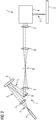
- Fig. 1 shows a schematic diagram of a device 1 according to an embodiment. It can be seen in Fig. 1 only the section of the device 1 relevant to the explanation of the principle described below is shown.
- the device 1 is used for the additive production of three-dimensional objects 2, i. H. in particular technical components or technical component groups, by successive, layer-by-layer selective exposure and the associated solidification of building material layers made of a solidifiable building material 3, d. H. z. B. a metal powder, by means of a laser beam 5.
- the selective solidification of the respective building material layers to be solidified takes place on the basis of object-related building data.
- Corresponding construction data describe the geometric or geometric-constructive shape of the object 2 to be produced additively.
- Corresponding construction data can contain, for example, “sliced” CAD data of the object 2 to be produced.
- the device 1 can comprise a process chamber (not shown in more detail) which can be inertized and in which the actual additive production of the respective objects 2 takes place.
- a process chamber In the process chamber, at least some of the functional components required to carry out additive construction processes, i.e. H. in particular a, as indicated by the horizontally aligned double arrow P1, movably mounted coating device 6, which is set up for the formation of building material layers to be solidified in a building plane, can be arranged or designed.
- the process chamber can form part of a housing structure (not shown) of the device 1.
- the device For the selective exposure of the respective layers of building material, the device comprises an exposure device 7 having a plurality of functional components.
- a first component of the exposure device 7 is a laser beam generation device 4.
- the laser beam generation device 4 is used to generate a laser beam 5 with at least one Laser beam parameters, ie in particular amplitude, phase, polarization, defined beam properties, ie in particular a defined beam profile, set up.
- the laser beam 5 generated by the laser beam generating device 4 can, for example, have a Gaussian beam profile.
- a collimator device 8 Arranged immediately downstream of the laser beam generating device 4 (optically) is a collimator device 8 comprising a collimator lens (not designated in more detail).
- the collimator device 8 is used for collimation, ie. H. for parallelization of the (divergent) laser beam 5 emanating from the laser beam generating device 4.
- the collimator device 8 is thus switched into the beam path of the laser beam 5.
- a modulation device 9 is arranged immediately downstream of the collimator device 8 (optically).
- the modulation device 9 is set up for the targeted change or modulation of at least one laser beam parameter of the laser beam 5 that influences the beam properties.
- the modulation device 9 is set up for the targeted change of at least one laser beam parameter of the laser beam 5 that influences the beam profile, ie for the targeted change of the beam profile of the laser beam 5.
- laser beams 5 with (almost) any beam properties, i.e. in particular also spatially and / or temporally variable, beam properties, in particular any beam profiles can be generated by deliberately changing corresponding laser beam parameters; reference is only made to Gaussian or top-hat profiles by way of example .
- the wavefront and thus the beam profile of the laser beam 5 can be changed in a targeted manner by means of the modulation device 9.
- a change in the wavefront or the beam profile can also be understood to mean a division of a (single) beam profile of the laser beam 5 into a plurality of discrete beam profiles, as further below in connection with the description of FIGS Fig. 6, 7 shown cross-sections or intensity profiles is explained.
- the targeted change which is possible by means of the modulation device 9, of the respective laser beam parameters influencing the beam properties of the laser beam 5 takes place on the basis of a, in particular, user-side, e.g. B. by programming, specifiable or predetermined target size.
- the target variable can relate to at least one laser beam parameter (target laser beam parameter) relating to the beam properties.
- the target variable can relate to a beam profile (target beam profile) of the laser beam 5.
- the device 1 For specifying corresponding target variables, the device 1 comprises a suitable input device (not shown), e.g. B. as part of a device-side user interface (not shown), via which a user (user-side) inputs, d. H. in particular image, text or voice inputs for specifying a corresponding target variable - generally for specifying a desired beam properties, d. H. in particular, a desired beam profile, having laser beam 5 - can do.
- a suitable input device e.g. B. as part of a device-side user interface (not shown)
- a user (user-side) inputs e.g. B. as part of a device-side user interface (not shown) via which a user (user-side) inputs, d. H. in particular image, text or voice inputs for specifying a corresponding target variable - generally for specifying a desired beam properties, d. H. in particular, a desired beam profile, having laser beam 5 - can do.
- the modulation device 9 is therefore assigned to the laser beam generating device 4.
- the assignment of the modulation device 9 to the laser beam generation device 4 is designed in such a way that the laser beam 5 emanating from or generated by the laser beam generation device 4 strikes the modulation device 9.
- the modulation device 9 is thus also switched into the beam path of the laser beam 5.
- the modulation device 9 comprises a plurality of optical modulation elements 10 which can be switched or switched into the beam path of the laser beam 5 and are set up to influence a laser beam parameter influencing the beam properties of at least one beam portion of the laser beam 5.
- a laser beam parameter influencing the beam properties of at least one beam portion of the laser beam 5.
- the beam portion striking a respective modulation element 10 can be changed in its beam properties, ie for example amplitude, phase and polarization, by means of the modulation element 10, so that overall a laser beam 5 with different beam properties results.
- the modulation elements 10 are arranged or formed in a housing structure 11 of the modulation device 9 switched into the beam path of the laser beam 5, in which they are present in a defined spatial arrangement and / or orientation (relative to one another).
- the modulation elements 10 are here, in particular pixel-like, in a row or column - an arrangement in several rows and / or columns is of course also conceivable - arranged or formed.
- the modulation elements 10 can be switched individually or in groups into a state (active state) that enables a laser beam parameter of the laser beam 5 that influences the beam properties of the laser beam 5.
- each modulation element 10 can be in a first state in which the respective modulation element 10 z. B. allows at least partial transmission or reflection of the laser beam 5 or a laser beam portion, and in a second state in which the respective modulation element 10 z. B. an at least partial transmission or reflection of the laser beam 5 or a laser beam portion does not allow to be switched.
- the control on which the switching of the modulation elements 10 is based can be carried out by a control device (not shown) associated with the modulation device 9.
- the control device communicates (directly or indirectly) with the device-side input device already mentioned, via which corresponding (user-side) predefinable or predefined target variables can be input.
- the modulation elements 10 are specifically liquid crystal elements.
- the modulation device 9 is therefore designed as a spatial light modulator, or SLM for short, which by means of a suitable arrangement, alignment and switching of corresponding liquid crystal elements for separate or cumulative influencing of one or more laser beam parameters, ie in particular the amplitude, of the Phase or polarization, of the laser beam 5 is set up. Consequently, the one that can be changed in a targeted manner via the modulation device 9 and influences the beam properties, in particular the beam profile Laser beam parameters in particular the amplitude, the phase or the polarization of the laser beam 5 or the wavefront of the laser beam 5 .
- the modulation device 9 can be set up by means of a targeted change in the phase of the laser beam 5 (without changing the intensity and polarization of the laser beam 5) based on a planar beam profile or a planar wavefront of the laser beam 5 a targeted phase change to generate a step-like or step-shaped beam profile or a step-like or step-shaped wave front of the laser beam 5.
- a targeted change in the phase of the laser beam 5 without changing the intensity and polarization of the laser beam 5
- a targeted phase change to generate a step-like or step-shaped beam profile or a step-like or step-shaped wave front of the laser beam 5.
- a mirror device 12 Arranged immediately downstream of the modulation device 9 (optically) is a mirror device 12 comprising a mirror element (unspecified).
- the mirror device 12 is used to deflect the laser beam 5 emanating from the modulation device 9 onto a Fourier lens arranged immediately downstream of the mirror device 12 (optically) (unspecified) comprehensive Fourier lens device 13.
- the mirror device 12 and the Fourier lens device 13 are thus also switched into the beam path of the laser beam 5.
- a beam deflection device 14 Arranged immediately downstream of the Fourier lens device 13 (optical) is a beam deflection device 14 (scanner device).
- the beam deflection device 14 serves for the targeted deflection of the laser beam 5 onto respective layers of building material that are to be selectively consolidated.
- the beam deflection device 14 thus forms the last component of the exposure device 7 switched into the beam path of the laser beam 5 before the laser beam 7 emerges from the exposure device 7.
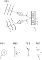
- Fig. 2 shows a schematic diagram of a device 1 according to a further exemplary embodiment. Can also be seen in Fig. 2 only the section of the device 1 relevant to the explanation of the principle described is shown.
- the embodiment shown is arranged immediately downstream of the mirror device 12 (optical) a first (or further) lens device 15 comprising an optical lens (not designated in more detail).
- the first lens device 15 is an optical spatial filter (unspecified), for. B. in the form of a pinhole, comprehensive room filter device 16 (optically) arranged immediately downstream.
- a second (or further) lens device 17 (optical) comprising a further optical lens (not designated in more detail) is arranged immediately downstream of the spatial filter device 16.
- the further lens device 17 is followed by the Fourier lens device 13 and the beam deflection device 14.
- a 4f imaging can be realized by the described arrangement of the above-mentioned optical elements arranged in the order mentioned.
- FIGS Figures 4-7 each show a basic illustration of a beam profile of a laser beam 5.
- FIGS Figures 4 and 6 in each case a cross section (based on the preparation direction of the laser beam 5) through a laser beam 5 changed by means of the modulation device 9 on the basis of a predeterminable or predefined target variable Fig. 5 is the intensity distribution to the in Fig. 4 cross section of the laser beam 5 shown in FIG Fig. 7 is the intensity distribution to the in Fig. 6 shown cross section of the laser beam 5 is shown.
- the modulation device 9 can also be used to divide a (single) beam profile of the laser beam 5 into several discrete beam profiles or wavefronts. Specifically, the laser beam 5 emanating from the laser beam generating device 4 is divided here into two point-like or point-shaped laser beams 5 with a comparatively pointed intensity distribution.
Landscapes
- Engineering & Computer Science (AREA)
- Chemical & Material Sciences (AREA)
- Physics & Mathematics (AREA)
- Materials Engineering (AREA)
- Optics & Photonics (AREA)
- Manufacturing & Machinery (AREA)
- Mechanical Engineering (AREA)
- Plasma & Fusion (AREA)
- Toxicology (AREA)
- Health & Medical Sciences (AREA)
- General Health & Medical Sciences (AREA)
- Ceramic Engineering (AREA)
- Automation & Control Theory (AREA)
- General Physics & Mathematics (AREA)
- Inorganic Chemistry (AREA)
- Structural Engineering (AREA)
- Organic Chemistry (AREA)
- Laser Beam Processing (AREA)
- Producing Shaped Articles From Materials (AREA)
- Powder Metallurgy (AREA)
Description
- Die Erfindung betrifft eine Vorrichtung zur additiven Herstellung dreidimensionaler Objekte durch sukzessives schichtweises selektives Belichten und damit einhergehendes Verfestigen von Baumaterialschichten aus einem vermittels eines von einer Laserstrahlerzeugungseinrichtung erzeugten Laserstrahls verfestigbaren Baumaterial.
- Entsprechende Vorrichtungen sind zur additiven Herstellung dreidimensionaler Objekte an und für sich bekannt. Typische Ausführungsformen entsprechender Vorrichtungen sind Vorrichtungen zur Durchführung selektiver Lasersinter- bzw. selektiver Laserschmelzverfahren. Eine wesentliche Funktionskomponente entsprechender Vorrichtungen stellt eine Laserstrahlerzeugungseinrichtung dar, welche zur Erzeugung des der selektiven Belichtung jeweiliger Baumaterialschichten dienenden Laserstrahls eingerichtet ist. Der Laserstrahl weist durch einen oder mehrere Laserstrahlparameter definierte Strahleigenschaften bzw. ein durch ein oder mehrere Laserstrahlparameter definiertes Strahlprofil auf.
- Die Laserstrahlerzeugungseinrichtungen bekannter Vorrichtungen erzeugen typischerweise Laserstrahlen mit einem gaußförmigen Intensitäts- bzw. Strahlprofil. Eine unter Umständen erforderliche Veränderung der Intensität des Laserstrahls ist hierbei nur durch eine Defokussierung bzw. eine Verschiebung der Fokuslage des Laserstrahls möglich; das Strahlprofil des Laserstrahls wird hierdurch jedoch nicht verändert. Gattungsgemäße Laserstrahlerzeugungseinrichtungen sind aus
US 2016/243649A1 undUS 2015/309473A1 bekannt. - Insbesondere im Hinblick auf eine größtmögliche Variabilität der mit einer entsprechenden Vorrichtung realisierbaren Belichtungsstrategien besteht jedoch ein Bedarf nach der Möglichkeit einer gezielten Veränderung der Strahleigenschaften, insbesondere des Strahlprofils, des von einer Laserstrahlerzeugungseinrichtung erzeugten Laserstrahls.
- Der Erfindung liegt die Aufgabe zugrunde, eine, insbesondere im Hinblick auf die Möglichkeit einer gezielten Veränderung der Strahleigenschaften, insbesondere des Strahlprofils, des von einer Laserstrahlerzeugungseinrichtung erzeugten Laserstrahls, verbesserte Vorrichtung zur additiven Herstellung dreidimensionaler Objekte anzugeben.
- Die Aufgabe wird durch eine Vorrichtung zur additiven Herstellung dreidimensionaler Objekte gemäß Anspruch 1 gelöst. Die hierzu abhängigen Ansprüche betreffen mögliche Ausführungsformen der Vorrichtung.
- Die hierin beschriebene Vorrichtung ("Vorrichtung") ist zur additiven Herstellung dreidimensionaler Objekte, d. h. beispielsweise technischer Bauteile bzw. technischer Bauteilgruppen, durch sukzessives schichtweises selektives Belichten und damit einhergehendes Verfestigen von Baumaterialschichten aus einem vermittels eines Laserstrahls verfestigbaren Baumaterial eingerichtet. Bei dem Baumaterial kann es sich insbesondere um ein partikuläres bzw. pulverförmiges Metall-, Kunststoff- und/oder Keramikmaterial handeln. Die selektive Verfestigung jeweiliger selektiv zu verfestigender Baumaterialschichten erfolgt auf Grundlage objektbezogener Baudaten. Entsprechende Baudaten beschreiben die geometrisch-konstruktive Gestalt des jeweils additiv herzustellenden Objekts und können beispielsweise "geslicte" CAD-Daten eines jeweiligen additiv herzustellenden Objekts beinhalten. Die Vorrichtung kann als SLM-Vorrichtung, d. h. als Vorrichtung zur Durchführung selektiver Laserschmelzverfahren (SLM-Verfahren), oder als SLS-Vorrichtung, d. h. als Vorrichtung zur Durchführung selektiver Lasersinterverfahren (SLS-Verfahren), ausgebildet sein.
- Die Vorrichtung umfasst die zur Durchführung additiver Bauvorgänge typischerweise erforderlichen Funktionskomponenten, d. h. insbesondere eine Laserstrahlerzeugungseinrichtung, welche zur Erzeugung eines Laserstrahls zur sukzessiven schichtweisen selektiven Verfestigung einzelner Baumaterialschichten eingerichtet ist, und eine Beschichtereinrichtung, welche zur Ausbildung selektiv zu verfestigender Baumaterialschichten in einer Bauebene eingerichtet ist. Bei einer Bauebene kann es sich um eine Oberfläche eines, typischerweise (in vertikaler Richtung) bewegbar gelagerten, Trägerelements einer Trägereinrichtung oder um eine Baumaterialschicht handeln. Im Allgemeinen ist in einer Bauebene wenigstens eine selektiv zu verfestigende bzw. selektiv verfestigte Baumaterialschicht ausgebildet. Vermittels der Vorrichtung durchgeführte additive Bauvorgänge erfolgen in einer der Vorrichtung zugehörigen, typischerweise inertisierbaren, Prozesskammer. Die Prozesskammer kann einen Teil einer Gehäusestruktur der Vorrichtung bilden.
- Die Laserstrahlerzeugungseinrichtung ist zur Erzeugung eines Laserstrahls mit durch wenigstens einen Laserstrahlparameter, d. h. insbesondere Amplitude, Phase, Polarisation, definierten Strahleigenschaften, d. h. insbesondere einem durch wenigstens einen Laserstrahlparameter definierten Strahlprofil, eingerichtet. Der von der Laserstrahlerzeugungseinrichtung erzeugte Laserstrahl kann beispielsweise ein gaußförmiges Strahlprofil aufweisen.
- Die Vorrichtung umfasst weiterhin eine Modulationseinrichtung. Die Modulationseinrichtung ist zur gezielten Veränderung bzw. Modulation wenigstens eines die Strahleigenschaften beeinflussenden Laserstrahlparameters des von der Laserstrahlerzeugungseinrichtung ausgehenden bzw. erzeugten Laserstrahls eingerichtet. Im Besonderen ist die Modulationseinrichtung zur gezielten Veränderung wenigstens eines das Strahlprofil beeinflussenden Laserstrahlparameters des von der Laserstrahlerzeugungseinrichtung erzeugten Laserstrahls, d. h. zur gezielten Veränderung des Strahlprofils des von der Laserstrahlerzeugungseinrichtung erzeugten Laserstrahls eingerichtet. Vermittels der Modulationseinrichtung lassen sich also durch gezielte Veränderung entsprechender Laserstrahlparameter Laserstrahlen mit (nahezu) beliebigen, d. h. insbesondere auch örtlich und/oder zeitlich veränderlichen, Strahleigenschaften, insbesondere beliebigen Strahlprofilen, lediglich beispielhaft sei auf Gauß- oder Top-Hat-Profile verwiesen, generieren. Insbesondere lässt sich vermittels der Modulationseinrichtung die Wellenfront des von der Laserstrahlerzeugungseinrichtung erzeugten Laserstrahls gezielt verändern. Da die Wellenfront das Strahlprofil maßgeblich bestimmt, geht eine Veränderung der Wellenfront typischerweise mit einer Veränderung des Strahlprofils des Laserstrahls einher. Unter einer Veränderung der Wellenfront bzw. des Strahlprofils kann auch eine Aufteilung einer (einzigen) Wellenfront bzw. eines (einzigen) Strahlprofils des von der Laserstrahlerzeugungseinrichtung erzeugten Laserstrahls in mehrere diskrete Strahlprofile bzw. Wellenfronten zu verstehen sein. Mithin kann ein Laserstrahl mit einem (einzigen) Fokusbereich vermittels der Modulationseinrichtung in mehrere Laserstrahlen mit jeweils einem Fokusbereich erzeugt werden.
- Die gezielte Veränderung bzw. Modulation des wenigstens einen die Strahleigenschaften beeinflussenden Laserstrahlparameters erfolgt auf Grundlage einer, insbesondere anwender- bzw. benutzerseitig, z. B. durch eine Programmierung, vorgebbaren bzw. vorgegebenen Zielgröße. Die Zielgröße kann im Allgemeinen wenigstens einen die Strahleigenschaften betreffenden Laserstrahlparameter (Soll-Laserstrahlparameter) betreffen. Im Besonderen kann die Zielgröße ein Strahlprofil (Soll-Strahlprofil) des Laserstrahls betreffen.
- Zur Vorgabe entsprechender Zielgrößen umfasst die Vorrichtung eine geeignete Eingabeeinrichtung, z. B. als Bestandteil einer vorrichtungsseitigen Benutzerschnittstelle, über welche ein Benutzer (benutzerseitige) Eingaben, d. h. insbesondere Bild-, Text- oder Spracheingaben, zur Vorgabe einer entsprechenden Zielgröße - im Allgemeinen zur Vorgabe eines gewünschte Strahleigenschaften, d. h. insbesondere ein gewünschtes Strahlprofil, aufweisenden Laserstrahls - tätigen kann. Eine entsprechende Eingabeeinrichtung kann z. B. als Touch-Screen-Einrichtung ausgebildet sein oder eine solche umfassen. Selbstverständlich ist es auch möglich, entsprechende Eingaben an einer externen, gleichwohl mit der Vorrichtung datenmäßig kommunizierenden Eingabeeinrichtung, z. B. als Bestandteil eines Computers, zu tätigen.
- Aus vorstehenden Ausführungen ergibt sich, dass die Modulationseinrichtung der Laserstrahlerzeugungseinrichtung zugeordnet ist. Die Zuordnung der Modulationseinrichtung zu der Laserstrahlerzeugungseinrichtung ist insbesondere derart gestaltet, dass der von der Laserstrahlerzeugungseinrichtung ausgehende bzw. erzeugte Laserstrahl auf die Modulationseinrichtung trifft. Die Modulationseinrichtung ist sonach in den Strahlengang des von der Laserstrahlerzeugungseinrichtung ausgehenden Laserstrahls schaltbar bzw. geschaltet. Die Laserstrahlerzeugungseinrichtung und die dieser zugeordnete Modulationseinrichtung können, neben einer etwaig vorhandenen Strahlablenkeinrichtung (Scannereinrichtung), die wesentlichen Bestandteile einer vorrichtungsseitigen Belichtungseinrichtung bilden.
- Durch die Implementierung einer entsprechenden Modulationseinrichtung ist eine, insbesondere im Hinblick auf die Möglichkeit einer gezielten Veränderung der Strahleigenschaften, insbesondere des Strahlprofils, des von einer Laserstrahlerzeugungseinrichtung erzeugten Laserstrahls, verbesserte Vorrichtung zur additiven Herstellung dreidimensionaler Objekte gegeben.
- Durch die Implementierung einer entsprechenden Modulationseinrichtung ergeben sich jedoch weitere Vorteile für die Vorrichtung bzw. die damit durchgeführten additiven Bauvorgänge:
Beispielsweise lässt sich durch eine vermittels der Modulationseinrichtung realisierbare gezielte Veränderung der Strahleigenschaften des Laserstrahls eine Erhöhung der Qualität der additiv herzustellenden bzw. hergestellten Objekte realisieren. Die Erhöhung der Qualität der additiv herzustellenden bzw. hergestellten Objekte begründet sich insbesondere damit, dass sich durch die gezielte Veränderung der Strahleigenschaften eine örtlich und/oder zeitlich aufgelöste Temperierung bzw. Temperatursteuerung selektiv zu verfestigender bzw. verfestigter Baumaterialschichten realisieren lässt. Dies ist insbesondere für die Verarbeitung schwer verarbeitbarer Baumaterialien, d. h. insbesondere Baumaterialien, welche sich nur in einem vergleichsweise engen Prozessfenster verarbeiten lassen, von Vorteil. Durch eine gezielte Veränderung der Strahleigenschaften lässt sich eine gezielte thermische Beeinflussung des Baumaterials um einen eigentlich zu verfestigenden Verfestigungsbereich, insbesondere Schmelzbereich bzw. -pool, in einer Baumaterialschicht realisieren. So kann ein die Verarbeitbarkeit des Baumaterials begünstigender Temperierungs- bzw. Wärmebehandlungseffekt erzielt werden. Auch die Einstellung unterschiedlicher Strahlprofile kann einen positiven Einfluss auf die Qualität der additiv herzustellenden bzw. hergestellten Objekte haben. - Durch eine vermittels der Modulationseinrichtung realisierbare gezielte Veränderung der Strahleigenschaften lässt sich weiterhin eine Reduzierung der Bauzeiten und somit eine Steigerung der Effizienz der vermittels der Vorrichtung durchführbaren additiven Bauvorgänge realisieren. Die Reduzierung der Bauzeiten bzw. die Steigerung der Effizienz begründet sich insbesondere damit, dass sich je nach Bedarf unterschiedliche, d. h. z. B. groß- oder kleinflächige, Strahlprofile realisieren lassen. Beispielsweise lassen sich durch eine Aufteilung eines, z. B. flächigen, Strahlprofils bzw. einer, z. B. flächigen, Wellenfront mehrere, z. B. streifenförmige, Strahlprofile bzw. mehrere, z. B. streifenförmige, Wellenfronten realisieren. Unabhängig von einer entsprechenden Aufteilung eines Strahlprofils in mehrere Strahlprofile kann auch die Einstellung unterschiedlicher Strahlprofile einen positiven Einfluss auf die Reduzierung der Bauzeiten der vermittels der Vorrichtung durchführbaren additiven Bauvorgänge haben.
- Durch eine vermittels der Modulationseinrichtung realisierbare gezielte Veränderung der Strahleigenschaften kann die Modulationseinrichtung ferner weitere (optische) Funktionen übernehmen, sodass der konstruktive Aufbau der Vorrichtung gegebenenfalls vereinfacht werden kann. Die Modulationseinrichtung kann beispielsweise zur Ablenkung bzw. Positionierung des Laserstrahls auf einer Baumaterialschicht dienen, sodass gegebenenfalls auf eine Strahlablenkeinrichtung verzichtet werden kann. Auch kann die Modulationseinrichtung zur Veränderung der Fokusebene dienen, sodass gegebenenfalls (auch) auf eine Einrichtung zur Einstellung der Fokusebene bzw. einer entsprechenden Einrichtung typischerweise zugehörige optische Elemente, insbesondere Linsen, verzichtet werden kann. Schließlich kann die Modulationseinrichtung (auch) zur Kollimation des Laserstrahls dienen, sodass gegebenenfalls (auch) auf eine Kollimationseinrichtung zur Kollimation des Laserstrahls verzichtet werden kann.
- Die Modulationseinrichtung kann mehrere, in den Strahlengang des von der Laserstrahlerzeugungseinrichtung ausgehenden bzw. erzeugten Laserstrahls schaltbare oder geschaltete optische Modulationselemente ("Modulationselemente") umfassen, welche zur Beeinflussung wenigstens eines die Strahleigenschaften beeinflussenden Laserstrahlparameters wenigstens eines Strahlanteils des von der Laserstrahlerzeugungseinrichtung erzeugten Laserstrahls eingerichtet sind. Je nach Anzahl und Anordnung jeweiliger Modulationselemente kann es sein, dass auf einzelne, mehrere oder sämtliche Modulationselemente ein bestimmter Strahlanteil des von der Laserstrahlerzeugungseinrichtung ausgehenden Laserstrahls trifft. Der auf ein jeweiliges Modulationselement treffende Strahlanteil kann vermittels des Modulationselements in seinen Strahleigenschaften, d. h. z. B. Amplitude, Phase und Polarisation, verändert werden, sodass sich insgesamt ein in seinen Strahleigenschaften, wie erwähnt, z. B. seinem Strahlprofil, veränderter Laserstrahl ergibt.
- Die Modulationselemente sind typischerweise in einer in den Strahlengang des Laserstrahls schaltbaren oder geschalteten Gehäusestruktur der Modulationseinrichtung angeordnet oder ausgebildet, in welcher diese typischerweise in einer definierten räumlichen Anordnung und/oder Ausrichtung (relativ zueinander) vorliegen. Die Modulationselemente können dabei, insbesondere pixelartig, in wenigstens einer Reihe und/oder Spalte angeordnet oder ausgebildet sein. Mithin können mehrere Modulationselemente in reihen- und/oder spaltenartig benachbarter Anordnung vorliegen.
- Die Modulationselemente können einzeln oder gruppenweise in einen eine Beeinflussung des wenigstens einen die Strahleigenschaften beeinflussenden Laserstrahlparameters des Laserstrahls ermöglichenden Zustand (aktiver Zustand) schaltbar sein. Insbesondere kann jedes Modulationselement in einen ersten Zustand, in welchem das jeweilige Modulationselement eine wenigstens teilweise Transmission oder Reflexion des Laserstrahls bzw. eines Laserstrahlanteils ermöglicht, und in einen zweiten Zustand, in welchem das jeweilige Modulationselement eine wenigstens teilweise Transmission oder Reflexion des Laserstrahls bzw. eines Laserstrahlanteils nicht ermöglicht, geschaltet werden. Die der Schaltung der Modulationselemente zugrunde liegende Steuerung kann durch eine der Modulationseinrichtung zugehörige Steuereinrichtung erfolgen. Die Steuereinrichtung kommuniziert typischerweise (unmittelbar oder mittelbar) mit der bereits erwähnten vorrichtungsseitigen Eingabeeinrichtung, über welche sich entsprechende (benutzerseitig) vorgebbare bzw. vorgegebene Zielgrößen eingeben lassen.
- Bei den Modulationselementen kann es sich konkret um Flüssigkristallelemente handeln bzw. können diese entsprechende Flüssigkristallelemente umfassen. Die Modulationseinrichtung kann sonach als räumlicher Lichtmodulator, engl.: "spatial light modulator", kurz SLM, ausgebildet sein, welcher vermittels einer geeigneten Anordnung, Ausrichtung und Schaltung entsprechender Flüssigkristallelemente zur separaten oder kumulativen Beeinflussung einzelner oder mehrerer Laserstrahlparameter, d. h. insbesondere der Amplitude, der Phase oder der Polarisation, des Laserstrahls eingerichtet ist.
- Aus vorstehendem Absatz ergibt sich, dass der über die Modulationseinrichtung gezielt veränderbare, die Strahleigenschaften, insbesondere das Strahlprofil, beeinflussende Laserstrahlparameter insbesondere die Amplitude, die Phase oder die Polarisation des Laserstrahls bzw. der Wellenfront des Laserstrahls sein kann. Die Modulationseinrichtung kann also insbesondere eingerichtet sein, die Amplitude, die Phase oder die Polarisation des Laserstrahls bzw. der Wellenfront des Laserstrahls gezielt zu verändern.
- Wie erwähnt, ist die Modulationseinrichtung typischerweise in den Strahlengang des von der Laserstrahlerzeugungseinrichtung ausgehenden bzw. erzeugten Laserstrahls schaltbar bzw. geschaltet. Die Modulationseinrichtung ist der Laserstrahlerzeugungseinrichtung sonach typischerweise (optisch) nachgeschaltet.
- Hiervon ausgehend ist die Modulationseinrichtung zwischen einer, insbesondere wenigstens eine Kollimatorlinse umfassenden, Kollimatoreinrichtung und einer optischen Spiegeleinrichtung angeordnet oder ausgebildet. Dabei kann die Modulationseinrichtung unmittelbar benachbart einerseits zu der Kollimatoreinrichtung und andererseits zu der Spiegeleinrichtung angeordnet oder ausgebildet sein. Gemäß einer beispielhaften Anordnung kann der Modulationseinrichtung eine optische Spiegeleinrichtung, eine, insbesondere eine optische Linse umfassende, erste Linseneinrichtung, eine, insbesondere einen optischen Raumfilter umfassende, Raumfiltereinrichtung eine, insbesondere eine weitere optische Linse umfassende, weitere Linseneinrichtung und eine, insbesondere eine Fourierlinse umfassende, Fourierlinseneinrichtung nachgeschaltet sein. Mithin lässt sich durch eine entsprechende Anordnung der vorstehend erwähnten, in der genannten Reihenfolge angeordneten optischen Elemente eine so genannte 4f-Abbildung realisieren. Aus vorstehenden Ausführungen ergibt sich, dass die Modulationseinrichtung im Allgemeinen in unterschiedlichen Anordnungen zwischen unterschiedlichen optischen Elementen der Vorrichtung bzw. einer vorrichtungsseitigen Belichtungseinrichtung angeordnet oder ausgebildet sein kann.
- Sofern vorhanden, ist der Modulationseinrichtung eine Strahlablenk- bzw. Scannereinrichtung, welche zur Ablenkung des Laserstrahls auf eine selektiv zu belichtende Baumaterialschicht eingerichtet ist, (optisch) nachgeschaltet. Die Strahlablenkeinrichtung bildet typischerweise das letzte in den Strahlengang geschaltete Bauelement vor Austritt des Laserstrahls aus einer vorrichtungsseitigen Belichtungseinrichtung, deren Bestandteile die Laserstrahlerzeugungseinrichtung und die Modulationseinrichtung, wie erwähnt, typischerweise bilden.
- Die Offenbarung betrifft auch eine Modulationseinrichtung für eine wie beschriebene Vorrichtung. Die Modulationseinrichtung ist zur gezielten Veränderung wenigstens eines die Strahleigenschaften, insbesondere das Strahlprofil, beeinflussenden Laserstrahlparameters eines von einer vorrichtungsseitigen Laserstrahlerzeugungseinrichtung erzeugten Laserstrahls auf Grundlage einer, insbesondere benutzerseitig, vorgebbaren oder vorgegebenen Zielgröße eingerichtet. Die vorstehenden Ausführungen im Zusammenhang mit der Vorrichtung gelten in analoger Weise für die Modulationseinrichtung.
Die Erfindung ist anhand von Ausführungsbeispielen in den Zeichnungsfiguren näher erläutert. Dabei zeigen: - Fig. 1, 2
- je eine Prinzipdarstellung einer Vorrichtung gemäß einem Ausführungsbeispiel;
- Fig. 3
- eine Prinzipdarstellung der in den
Fig. 1 ,2 gezeigten Einzelheit III; und - Fig. 4 - 7
- je eine Prinzipdarstellung eines Strahlprofils.
-
Fig. 1 zeigt eine Prinzipdarstellung einer Vorrichtung 1 gemäß einem Ausführungsbeispiel. Ersichtlich ist inFig. 1 nur der für die Erläuterung des nachfolgend beschriebenen Prinzips relevante Ausschnitt der Vorrichtung 1 gezeigt. - Die Vorrichtung 1 dient der additiven Herstellung dreidimensionaler Objekte 2, d. h. insbesondere technischer Bauteile bzw. technischer Bauteilgruppen, durch sukzessives schichtweises selektives Belichten und damit einhergehendes Verfestigen von Baumaterialschichten aus einem verfestigbaren Baumaterial 3, d. h. z. B. eines Metallpulvers, vermittels eines Laserstrahls 5. Die selektive Verfestigung jeweiliger zu verfestigender Baumaterialschichten erfolgt auf Grundlage von objektbezogenen Baudaten. Entsprechende Baudaten beschreiben die geometrische bzw. geometrisch-konstruktive Gestalt des jeweils additiv herzustellenden Objekts 2. Entsprechende Baudaten können beispielsweise "geslicte" CAD-Daten des herzustellenden Objekts 2 beinhalten.
- Die Vorrichtung 1 kann eine inertisierbare Prozesskammer (nicht näher gezeigt) umfassen, in welcher die eigentliche additive Herstellung jeweiliger Objekte 2 erfolgt. In der Prozesskammer kann wenigstens ein Teil der zur Durchführung additiver Bauvorgänge erforderlichen Funktionskomponenten, d. h. insbesondere eine, wie durch den horizontal ausgerichteten Doppelpfeil P1 angedeutet, bewegbar gelagerte Beschichtereinrichtung 6, welche zur Ausbildung zu verfestigender Baumaterialschichten in einer Bauebene eingerichtet ist, angeordnet bzw. ausgebildet sein. Die Prozesskammer kann einen Teil einer Gehäusestruktur (nicht gezeigt) der Vorrichtung 1 bilden.
- Zur selektiven Belichtung jeweiliger Baumaterialschichten umfasst die Vorrichtung eine mehrere funktionelle Bestandteile aufweisende Belichtungseinrichtung 7. Aufbau bzw. Funktion der funktionellen Bestandteile der Belichtungseinrichtung 7 werden im Weiteren erläutert:
Ein erster Bestandteil der Belichtungseinrichtung 7 ist eine Laserstrahlerzeugungseinrichtung 4. Die Laserstrahlerzeugungseinrichtung 4 ist zur Erzeugung eines Laserstrahls 5 mit durch wenigstens einen Laserstrahlparameter, d. h. insbesondere Amplitude, Phase, Polarisation, definierten Strahleigenschaften, d. h. insbesondere einem definierten Strahlprofil, eingerichtet. Der von der Laserstrahlerzeugungseinrichtung 4 erzeugte Laserstrahl 5 kann beispielsweise ein gaußförmiges Strahlprofil aufweisen. - Der Laserstrahlerzeugungseinrichtung 4 (optisch) unmittelbar nachgeschaltet angeordnet ist eine Kollimatorlinse (nicht näher bezeichnet) umfassende Kollimatoreinrichtung 8. Die Kollimatoreinrichtung 8 dient zur Kollimation, d. h. zur Parallelisierung, des von der Laserstrahlerzeugungseinrichtung 4 ausgehenden (divergenten) Laserstrahls 5. Die Kollimatoreinrichtung 8 ist damit in den Strahlengang des Laserstrahls 5 geschaltet.
- Der Kollimatoreinrichtung 8 (optisch) unmittelbar nachgeschaltet angeordnet ist eine Modulationseinrichtung 9. Die Modulationseinrichtung 9 ist zur gezielten Veränderung bzw. Modulation wenigstens eines die Strahleigenschaften beeinflussenden Laserstrahlparameters des Laserstrahls 5 eingerichtet. Im Besonderen ist die Modulationseinrichtung 9 zur gezielten Veränderung wenigstens eines das Strahlprofil beeinflussenden Laserstrahlparameters des Laserstrahls 5, d. h. zur gezielten Veränderung des Strahlprofils des Laserstrahls 5 eingerichtet. Vermittels der Modulationseinrichtung 9 lassen sich durch gezielte Veränderung entsprechender Laserstrahlparameter Laserstrahlen 5 mit (nahezu) beliebigen, d. h. insbesondere auch örtlich und/oder zeitlich veränderlichen, Strahleigenschaften, insbesondere beliebigen Strahlprofilen, lediglich beispielhaft sei auf Gauß- oder Top-Hat-Profile verwiesen, generieren. Insbesondere lässt sich vermittels der Modulationseinrichtung 9 die Wellenfront und somit das Strahlprofil des Laserstrahls 5 gezielt verändern. Unter einer Veränderung der Wellenfront bzw. des Strahlprofils kann auch eine Aufteilung eines (einzigen) Strahlprofils des Laserstrahls 5 in mehrere diskrete Strahlprofile zu verstehen sein, wie weiter unten im Zusammenhang mit der Beschreibung der in den
Fig. 6, 7 gezeigten Querschnitte bzw. Intensitätsprofile erläutert wird. - Die vermittels der Modulationseinrichtung 9 mögliche gezielte Veränderung jeweiliger die Strahleigenschaften des Laserstrahls 5 beeinflussender Laserstrahlparameter erfolgt auf Grundlage einer, insbesondere anwender- bzw. benutzerseitig, z. B. durch eine Programmierung, vorgebbaren bzw. vorgegebenen Zielgröße. Die Zielgröße kann wenigstens einen die Strahleigenschaften betreffenden Laserstrahlparameter (Soll-Laserstrahlparameter) betreffen. Im Besonderen kann die Zielgröße ein Strahlprofil (Soll-Strahlprofil) des Laserstrahls 5 betreffen.
- Zur Vorgabe entsprechender Zielgrößen umfasst die Vorrichtung 1 eine geeignete Eingabeeinrichtung (nicht gezeigt), z. B. als Bestandteil einer vorrichtungsseitigen Benutzerschnittstelle (nicht gezeigt), über welche ein Benutzer (benutzerseitige) Eingaben, d. h. insbesondere Bild-, Text- oder Spracheingaben, zur Vorgabe einer entsprechenden Zielgröße - im Allgemeinen zur Vorgabe eines gewünschte Strahleigenschaften, d. h. insbesondere ein gewünschtes Strahlprofil, aufweisenden Laserstrahls 5 - tätigen kann.
- Die Modulationseinrichtung 9 ist der Laserstrahlerzeugungseinrichtung 4 sonach zugeordnet. Die Zuordnung der Modulationseinrichtung 9 zu der Laserstrahlerzeugungseinrichtung 4 ist derart gestaltet, dass der von der Laserstrahlerzeugungseinrichtung 4 ausgehende bzw. erzeugte Laserstrahl 5 auf die Modulationseinrichtung 9 trifft. Die Modulationseinrichtung 9 ist damit ebenso in den Strahlengang des Laserstrahls 5 geschaltet.
- Wie sich aus der eine Prinzipdarstellung der in den
Fig. 1 ,2 gezeigten Einzelheit III zeigendenFig. 3 ergibt, umfasst die Modulationseinrichtung 9 mehrere in den Strahlengang des Laserstrahls 5 schaltbare bzw. geschaltete optische Modulationselemente 10, welche zur Beeinflussung eines die Strahleigenschaften beeinflussenden Laserstrahlparameters wenigstens eines Strahlanteils des Laserstrahls 5 eingerichtet sind. Je nach Anzahl und Anordnung jeweiliger Modulationselemente 10 kann es sein, dass auf einzelne, mehrere oder sämtliche Modulationselemente 10 ein bestimmter Strahlanteil des Laserstrahls 5 trifft. Der auf ein jeweiliges Modulationselement 10 treffende Strahlanteil kann vermittels des Modulationselements 10 in seinen Strahleigenschaften, d. h. z. B. Amplitude, Phase und Polarisation, verändert werden, sodass sich insgesamt ein in seinen Strahleigenschaften veränderter Laserstrahl 5 ergibt. - Anhand von
Fig. 3 ist ersichtlich, dass die Modulationselemente 10 in einer in den Strahlengang des Laserstrahls 5 geschalteten Gehäusestruktur 11 der Modulationseinrichtung 9 angeordnet bzw. ausgebildet sind, in welcher diese in einer definierten räumlichen Anordnung und/oder Ausrichtung (relativ zueinander) vorliegen. Die Modulationselemente 10 sind dabei, insbesondere pixelartig, in einer Reihe bzw. Spalte - selbstverständlich ist eine Anordnung in mehreren Reihen und/oder Spalten ebenso denkbar - angeordnet bzw. ausgebildet. - Die Modulationselemente 10 können einzeln oder gruppenweise in einen eine Beeinflussung eines die Strahleigenschaften des Laserstrahls 5 beeinflussenden Laserstrahlparameters des Laserstrahls 5 ermöglichenden Zustand (aktiver Zustand) schaltbar sein. Insbesondere kann jedes Modulationselement 10 in einen ersten Zustand, in welchem das jeweilige Modulationselement 10 z. B. eine wenigstens teilweise Transmission oder Reflexion des Laserstrahls 5 bzw. eines Laserstrahlanteils ermöglicht, und in einen zweiten Zustand, in welchem das jeweilige Modulationselement 10 z. B. eine wenigstens teilweise Transmission oder Reflexion des Laserstrahls 5 bzw. eines Laserstrahlanteils nicht ermöglicht, geschaltet werden. Die der Schaltung der Modulationselemente 10 zugrunde liegende Steuerung kann durch eine der Modulationseinrichtung 9 zugehörige Steuereinrichtung (nicht gezeigt) erfolgen. Die Steuereinrichtung kommuniziert (unmittelbar oder mittelbar) mit der bereits erwähnten vorrichtungsseitigen Eingabeeinrichtung, über welche sich entsprechende (benutzerseitig) vorgebbare bzw. vorgegebene Zielgrößen eingeben lassen.
- Bei den Modulationselementen 10 handelt es sich konkret um Flüssigkristallelemente. Die Modulationseinrichtung 9 ist sonach als räumlicher Lichtmodulator, engl.: "spatial light modulator", kurz SLM, ausgebildet, welcher vermittels einer geeigneten Anordnung, Ausrichtung und Schaltung entsprechender Flüssigkristallelemente zur separaten oder kumulativen Beeinflussung einzelner oder mehrerer Laserstrahlparameter, d. h. insbesondere der Amplitude, der Phase oder der Polarisation, des Laserstrahls 5 eingerichtet ist. Mithin ist der über die Modulationseinrichtung 9 gezielt veränderbare, die Strahleigenschaften, insbesondere das Strahlprofil, beeinflussende Laserstrahlparameter insbesondere die Amplitude, die Phase oder die Polarisation des Laserstrahls 5 bzw. der Wellenfront des Laserstrahls 5. Die Modulationseinrichtung 9 ist also insbesondere eingerichtet, die Amplitude, die Phase oder die Polarisation des Laserstrahls 5 bzw. der Wellenfront des Laserstrahls 5 gezielt zu verändern.
- In dem in
Fig. 3 gezeigten Ausführungsbeispiel ist veranschaulicht, dass die Modulationseinrichtung 9 dazu eingerichtet sein kann, vermittels einer gezielten Veränderung der Phase des Laserstrahls 5 (ohne Veränderung der Intensität und der Polarisation des Laserstrahls 5) ausgehend von einem planen Strahlprofil bzw. einer planen Wellenfront des Laserstrahls 5 ein aufgrund einer gezielten Phasenveränderung stufenartiges bzw. -förmiges Strahlprofil bzw. eine stufenartige bzw. -förmige Wellenfront des Laserstrahls 5 zu erzeugen. Dies ist selbstverständlich rein beispielhaft zu verstehen. - Der Modulationseinrichtung 9 (optisch) unmittelbar nachgeschaltet angeordnet ist eine ein Spiegelelement (nicht näher bezeichnet) umfassende Spiegeleinrichtung 12. Die Spiegeleinrichtung 12 dient zur Ablenkung des von der Modulationseinrichtung 9 ausgehenden Laserstrahls 5 auf eine der Spiegeleinrichtung 12 (optisch) unmittelbar nachgeschaltet angeordnete, eine Fourierlinse (nicht näher bezeichnet) umfassende Fourierlinseneinrichtung 13. Die Spiegeleinrichtung 12 und die Fourierlinseneinrichtung 13 sind damit ebenso in den Strahlengang des Laserstrahls 5 geschaltet.
- Der Fourierlinseneinrichtung 13 (optisch) unmittelbar nachgeschaltet angeordnet ist eine Strahlablenkeinrichtung 14 (Scannereinrichtung). Die Strahlablenkeinrichtung 14 dient zur gezielten Ablenkung des Laserstrahls 5 auf jeweilige selektiv zu verfestigende Baumaterialschichten. Die Strahlablenkeinrichtung 14 bildet damit den letzten in den Strahlengang des Laserstrahls 5 geschalteten Bestandteil der Belichtungseinrichtung 7 vor Austritt des Laserstrahls 7 aus der Belichtungseinrichtung 7.
-
Fig. 2 zeigt eine Prinzipdarstellung einer Vorrichtung 1 gemäß einem weiteren Ausführungsbeispiel. Ersichtlich ist auch inFig. 2 nur der für die Erläuterung des beschriebenen Prinzips relevante Ausschnitt der Vorrichtung 1 gezeigt. - In dem in
Fig. 2 gezeigten Ausführungsbeispiel ist der Spiegeleinrichtung 12 eine eine optische Linse (nicht näher bezeichnet) umfassende erste (bzw. weitere) Linseneinrichtung 15 (optisch) unmittelbar nachgeschaltet angeordnet. Der ersten Linseneinrichtung 15 ist eine einen optischen Raumfilter (nicht näher bezeichnet), z. B. in Form eines Pinholes, umfassende Raumfiltereinrichtung 16 (optisch) unmittelbar nachgeschaltet angeordnet. Der Raumfiltereinrichtung 16 ist eine eine weitere optische Linse (nicht näher bezeichnet) umfassende zweite (bzw. weitere) Linseneinrichtung 17 (optisch) unmittelbar nachgeschaltet angeordnet. Der weiteren Linseneinrichtung 17 sind die Fourierlinseneinrichtung 13 und die Strahlablenkeinrichtung 14 nachgeschaltet. Durch die beschriebene Anordnung der vorstehend erwähnten, in der genannten Reihenfolge angeordneten optischen Elemente ist eine 4f-Abbildung realisierbar. - Die
Fig. 4 - 7 zeigen je eine Prinzipdarstellung eines Strahlprofils eines Laserstrahls 5. Dabei zeigen dieFig. 4 und 6 jeweils einen Querschnitt (bezogen auf die Ausbereitungsrichtung des Laserstrahls 5) durch einen vermittels der Modulationseinrichtung 9 auf Grundlage einer vorgebbaren bzw. vorgegebenen Zielgröße veränderten Laserstrahl 5. InFig. 5 ist die Intensitätsverteilung zu dem inFig. 4 gezeigten Querschnitt des Laserstrahls 5, inFig. 7 ist die Intensitätsverteilung zu dem inFig. 6 gezeigten Querschnitt des Laserstrahls 5 dargestellt. - Anhand der
Fig. 4, 6 ist ersichtlich, dass sich vermittels der Modulationseinrichtung 9 z. B. querschnittlich (kreis)runde Laserstrahlen 5 mit einer in radialer Richtung veränderlichen Intensität - konkret nimmt die Intensität in radialer Richtung von innen nach außen ab - erzeugen lassen. - Anhand der
Fig. 5, 7 ist ersichtlich, dass sich vermittels der Modulationseinrichtung 9 auch eine Aufteilung eines (einzigen) Strahlprofils des Laserstrahls 5 in mehrere diskrete Strahlprofile bzw. Wellenfronten realisieren lässt. Konkret ist der von der Laserstrahlerzeugungseinrichtung 4 ausgehende Laserstrahl 5 hier in zwei punktartige bzw. -förmige Laserstahlen 5 mit einer vergleichsweise spitz zulaufenden Intensitätsverteilung aufgeteilt.
Claims (10)
- Vorrichtung (1) zur additiven Herstellung dreidimensionaler Objekte (2) durch sukzessives schichtweises selektives Belichten und damit einhergehendes Verfestigen von Baumaterialschichten aus einem vermittels eines von einer Laserstrahlerzeugungseinrichtung (4) erzeugten Laserstrahls (5) verfestigbaren Baumaterial (3), umfassend:- eine Laserstrahlerzeugungseinrichtung (4), welche zur Erzeugung eines Laserstrahls (5) mit durch wenigstens einen Laserstrahlparameter definierten Strahleigenschaften, insbesondere einem durch wenigstens einen Laserstrahlparameter definierten Strahlprofil, eingerichtet ist;- eine der Laserstrahlerzeugungseinrichtung (4) zugeordnete Modulationseinrichtung (9), welche zur gezielten Veränderung wenigstens eines die Strahleigenschaften, insbesondere das Strahlprofil, beeinflussenden Laserstrahlparameters des von der Laserstrahlerzeugungseinrichtung (4) erzeugten Laserstrahls (5) auf Grundlage einer, insbesondere benutzerseitig, vorgebbaren oder vorgegebenen Zielgröße eingerichtet ist, dadurch gekennzeichnet, dass die Modulationseinrichtung (9) der Laserstrahlerzeugungseinrichtung (4) nachgeschaltet ist, wobei sie zwischen einer Kollimatoreinrichtung (8) und einer optischen Spiegeleinrichtung (12) angeordnet oder ausgebildet ist.
- Vorrichtung nach Anspruch 1, dadurch gekennzeichnet, dass die Modulationseinrichtung (9) mehrere, in den Strahlengang des von der Laserstrahlerzeugungseinrichtung (4) erzeugten Laserstrahls (5) schaltbare oder geschaltete optische Modulationselemente (10) umfasst, welche zur Beeinflussung wenigstens eines die Strahleigenschaften beeinflussenden Laserstrahlparameters wenigstens eines Strahlanteils des von der Laserstrahlerzeugungseinrichtung (4) erzeugten Laserstrahls (5) eingerichtet sind.
- Vorrichtung nach Anspruch 2, dadurch gekennzeichnet, dass die optischen Modulationselemente (10), insbesondere pixelartig, in wenigstens einer Reihe und/oder Spalte angeordnet oder ausgebildet sind.
- Vorrichtung nach Anspruch 2 oder 3, dadurch gekennzeichnet, dass die optischen Modulationselemente (10) einzeln oder gruppenweise in einen eine Beeinflussung des wenigstens einen die Strahleigenschaften beeinflussenden Laserstrahlparameters des Laserstrahls (5) ermöglichenden Zustand schaltbar sind.
- Vorrichtung nach einem der Ansprüche 2 bis 4, dadurch gekennzeichnet, dass ein optisches Modulationselement (10) als ein Flüssigkristallelement ausgebildet ist oder wenigstens ein solches umfasst.
- Vorrichtung nach einem der vorhergehenden Ansprüche, dadurch gekennzeichnet, dass die Modulationseinrichtung (9) als ein räumlicher Lichtmodulator ausgebildet ist oder einen solchen umfasst.
- Vorrichtung nach einem der vorhergehenden Ansprüche, dadurch gekennzeichnet, dass die Kollimatoreinrichtung (8) wenigstens eine Kollimatorlinse umfasst.
- Vorrichtung nach einem der vorhergehenden Ansprüche, dadurch gekennzeichnet, dass die Modulationseinrichtung (9) der Laserstrahlerzeugungseinrichtung (4) optisch nachgeschaltet ist, wobei der Modulationseinrichtung (9) eine optische Spiegeleinrichtung (12), eine, insbesondere eine optische Linse umfassende, erste Linseneinrichtung (15), eine, insbesondere einen optischen Raumfilter umfassende, Raumfiltereinrichtung (16) eine, insbesondere eine weitere optische Linse umfassende, weitere Linseneinrichtung (17) und eine, insbesondere eine Fourierlinse umfassende, Fourierlinseneinrichtung (13) nachgeschaltet ist.
- Vorrichtung nach einem der vorhergehenden Ansprüche, dadurch gekennzeichnet, dass der Modulationseinrichtung (9) eine Strahlablenkeinrichtung (14), welche zur Ablenkung des Laserstrahls (5) auf eine selektiv zu belichtende Baumaterialschicht eingerichtet ist, nachgeschaltet ist.
- Vorrichtung nach einem der vorhergehenden Ansprüche, dadurch gekennzeichnet, dass der über die Modulationseinrichtung (9) gezielt veränderbare, die Strahleigenschaften, insbesondere das Strahlprofil, beeinflussende Laserstrahlparameter
die Amplitude des Laserstrahls (5), insbesondere der Wellenfront des Laserstrahls (5), ist, wobei die Modulationseinrichtung (9) eingerichtet ist, die Amplitude des Laserstrahls (5) zu verändern, und/oder die die Phase des Laserstrahls (5), insbesondere der Wellenfront des Laserstrahls (5), ist, wobei die Modulationseinrichtung (9) eingerichtet ist, die Phase des Laserstrahls (5) zu verändern, und/oder die Polarisation des Laserstrahls (5), insbesondere der Wellenfront des Laserstrahls (5), ist, wobei die Modulationseinrichtung (9) eingerichtet ist, die Polarisation des Laserstrahls (5) zu verändern.
Applications Claiming Priority (1)
| Application Number | Priority Date | Filing Date | Title |
|---|---|---|---|
| DE102016120244.4A DE102016120244A1 (de) | 2016-10-24 | 2016-10-24 | Vorrichtung zur additiven Herstellung dreidimensionaler Objekte |
Publications (3)
| Publication Number | Publication Date |
|---|---|
| EP3312010A1 EP3312010A1 (de) | 2018-04-25 |
| EP3312010B1 true EP3312010B1 (de) | 2021-08-04 |
| EP3312010B2 EP3312010B2 (de) | 2025-03-26 |
Family
ID=59070507
Family Applications (1)
| Application Number | Title | Priority Date | Filing Date |
|---|---|---|---|
| EP17176129.9A Active EP3312010B2 (de) | 2016-10-24 | 2017-06-14 | Vorrichtung zur additiven herstellung dreidimensionaler objekte |
Country Status (5)
| Country | Link |
|---|---|
| US (1) | US11020903B2 (de) |
| EP (1) | EP3312010B2 (de) |
| JP (2) | JP2018070995A (de) |
| CN (1) | CN107972274A (de) |
| DE (1) | DE102016120244A1 (de) |
Cited By (1)
| Publication number | Priority date | Publication date | Assignee | Title |
|---|---|---|---|---|
| WO2023099244A1 (de) * | 2021-12-02 | 2023-06-08 | Trumpf Laser- Und Systemtechnik Gmbh | Vorrichtung und verfahren zum bearbeiten eines werkstücks |
Families Citing this family (10)
| Publication number | Priority date | Publication date | Assignee | Title |
|---|---|---|---|---|
| DE102018106579A1 (de) * | 2018-03-20 | 2019-09-26 | Pulsar Photonics Gmbh | Verfahren zur Bearbeitung eines Werkstücks mittels Bestrahlung mit Laserstrahlung sowie Vorrichtung hierzu |
| EP3597405A1 (de) * | 2018-07-18 | 2020-01-22 | Concept Laser GmbH | Vorrichtung zur generativen fertigung dreidimensionaler objekte |
| US11167375B2 (en) | 2018-08-10 | 2021-11-09 | The Research Foundation For The State University Of New York | Additive manufacturing processes and additively manufactured products |
| EP3644010B1 (de) * | 2018-10-26 | 2022-05-11 | Concept Laser GmbH | Bestimmungsvorrichtung zur bestimmung von mindestens einem parameter eines energiestrahls |
| DE102018128266A1 (de) * | 2018-11-12 | 2020-05-14 | Eos Gmbh Electro Optical Systems | Verfahren und Vorrichtung zum Bestrahlen eines Materials mit einem Energiestrahl |
| DE102019201280A1 (de) | 2019-01-31 | 2020-08-06 | Trumpf Laser Gmbh | Anordnung und Verfahren zum Formen eines Laserstrahls |
| JP7346724B2 (ja) | 2019-09-30 | 2023-09-19 | エスエルエム ソルーションズ グループ アーゲー | 積層造形技術を使用して3次元ワークピースを製造するための装置で使用するシステム、積層造形を使用して3次元ワークピースを製造するための装置の照射ユニットを制御する制御ユニット、積層造形技術を使用して3次元ワークピースを製造するための装置及び積層造形技術を使用して3次元ワークピースを製造するための装置の照射ビームを制御する方法 |
| JP7395410B2 (ja) * | 2020-04-06 | 2023-12-11 | 株式会社Screenホールディングス | 光学装置および3次元造形装置 |
| JP7538016B2 (ja) * | 2020-11-30 | 2024-08-21 | 株式会社Screenホールディングス | 光学装置および3次元造形装置 |
| PL4079446T3 (pl) * | 2021-04-19 | 2025-02-17 | Akzenta Paneele + Profile Gmbh | Sposób wytwarzania panelu dekoracyjnego o ulepszonej strukturze |
Citations (5)
| Publication number | Priority date | Publication date | Assignee | Title |
|---|---|---|---|---|
| JP2009006509A (ja) | 2007-06-26 | 2009-01-15 | Panasonic Electric Works Co Ltd | 三次元形状造形物の製造方法及び製造装置 |
| EP2335848A1 (de) | 2009-12-04 | 2011-06-22 | SLM Solutions GmbH | Optische Bestrahlungseinheit für eine Anlage zur Herstellung von Werkstücken durch Bestrahlen von Pulverschichten mit Laserstrahlung |
| US20160243649A1 (en) | 2014-07-10 | 2016-08-25 | Guangzhou Institute of Advanced Technology, Chinise Academy of Sciences | Optical system for 3d printing and control method thereof |
| WO2016146185A1 (en) * | 2015-03-18 | 2016-09-22 | Ettore Maurizio Costabeber | STEREOLlTHOGRAPHY MACHINE WITH IMPROVED OPTICAL UNIT |
| US20160288254A1 (en) | 2015-04-06 | 2016-10-06 | Fracturelab, Llc | Apparatus and method for precision thermal processing of a body |
Family Cites Families (23)
| Publication number | Priority date | Publication date | Assignee | Title |
|---|---|---|---|---|
| JPH04267132A (ja) * | 1991-02-22 | 1992-09-22 | Seiko Epson Corp | 立体成形装置 |
| JP3475947B2 (ja) * | 1991-05-21 | 2003-12-10 | セイコーエプソン株式会社 | 光学装置 |
| JP2597464B2 (ja) * | 1994-03-29 | 1997-04-09 | 株式会社ジーティシー | レーザアニール装置 |
| JP4356161B2 (ja) * | 1999-12-20 | 2009-11-04 | 株式会社安川電機 | 描画装置 |
| JP2002316363A (ja) | 2001-02-16 | 2002-10-29 | Fuji Photo Film Co Ltd | 光造形装置及び露光ユニット |
| JP4201506B2 (ja) * | 2002-01-24 | 2008-12-24 | オムロンレーザーフロント株式会社 | レーザ加工方法並びに加工機 |
| WO2003085457A1 (en) * | 2002-04-10 | 2003-10-16 | Fuji Photo Film Co., Ltd. | Exposure head, exposure apparatus, and its application |
| JP2005254281A (ja) * | 2004-03-11 | 2005-09-22 | Mitsubishi Electric Corp | レーザ加工装置 |
| US7423818B2 (en) * | 2005-07-15 | 2008-09-09 | Electro Scientific Industries, Inc. | Method of suppressing distortion of a working laser beam of a laser link processing system |
| FR2904701B1 (fr) * | 2006-08-01 | 2009-01-23 | Breizhtech Soc Par Actions Sim | Traitement vectoriel numerique multifaisceaux |
| US9044824B2 (en) | 2006-10-30 | 2015-06-02 | Flemming Ove Olsen | Method and system for laser processing |
| JP2010036189A (ja) * | 2008-07-31 | 2010-02-18 | Miyachi Technos Corp | レーザ加工装置 |
| JP5368033B2 (ja) | 2008-09-01 | 2013-12-18 | 浜松ホトニクス株式会社 | レーザ光照射装置およびレーザ光照射方法 |
| JP5446631B2 (ja) | 2009-09-10 | 2014-03-19 | アイシン精機株式会社 | レーザ加工方法及びレーザ加工装置 |
| JP5593055B2 (ja) * | 2009-10-30 | 2014-09-17 | 京セラドキュメントソリューションズ株式会社 | 光走査装置及びこれを備えた画像形成装置 |
| JP2011143681A (ja) * | 2010-01-18 | 2011-07-28 | Univ Of Tokyo | 光造形装置、光造形方法及び造形物 |
| US9492969B2 (en) * | 2010-05-28 | 2016-11-15 | Lawrence Livermore National Security, Llc | High resolution projection micro stereolithography system and method |
| US20130112672A1 (en) * | 2011-11-08 | 2013-05-09 | John J. Keremes | Laser configuration for additive manufacturing |
| FR2989294B1 (fr) * | 2012-04-13 | 2022-10-14 | Centre Nat Rech Scient | Dispositif et methode de nano-usinage par laser |
| DE102012207220A1 (de) * | 2012-04-30 | 2013-10-31 | Robert Bosch Gmbh | Verfahren zur Bearbeitung eines Werkstücks mit Laserstrahlung |
| JP5832412B2 (ja) | 2012-11-12 | 2015-12-16 | 三菱重工業株式会社 | 光学系及びレーザ加工装置 |
| US20170304894A1 (en) * | 2014-11-10 | 2017-10-26 | Velo3D, Inc. | Printing three-dimensional objects using beam array |
| US9700996B2 (en) | 2015-05-01 | 2017-07-11 | Dayana Hansley | Multipurpose tool for compromised environments |
-
2016
- 2016-10-24 DE DE102016120244.4A patent/DE102016120244A1/de active Pending
-
2017
- 2017-06-14 EP EP17176129.9A patent/EP3312010B2/de active Active
- 2017-08-18 CN CN201710711121.0A patent/CN107972274A/zh active Pending
- 2017-09-13 JP JP2017175389A patent/JP2018070995A/ja active Pending
- 2017-10-20 US US15/789,352 patent/US11020903B2/en active Active
-
2020
- 2020-01-07 JP JP2020000796A patent/JP2020097786A/ja active Pending
Patent Citations (5)
| Publication number | Priority date | Publication date | Assignee | Title |
|---|---|---|---|---|
| JP2009006509A (ja) | 2007-06-26 | 2009-01-15 | Panasonic Electric Works Co Ltd | 三次元形状造形物の製造方法及び製造装置 |
| EP2335848A1 (de) | 2009-12-04 | 2011-06-22 | SLM Solutions GmbH | Optische Bestrahlungseinheit für eine Anlage zur Herstellung von Werkstücken durch Bestrahlen von Pulverschichten mit Laserstrahlung |
| US20160243649A1 (en) | 2014-07-10 | 2016-08-25 | Guangzhou Institute of Advanced Technology, Chinise Academy of Sciences | Optical system for 3d printing and control method thereof |
| WO2016146185A1 (en) * | 2015-03-18 | 2016-09-22 | Ettore Maurizio Costabeber | STEREOLlTHOGRAPHY MACHINE WITH IMPROVED OPTICAL UNIT |
| US20160288254A1 (en) | 2015-04-06 | 2016-10-06 | Fracturelab, Llc | Apparatus and method for precision thermal processing of a body |
Non-Patent Citations (1)
| Title |
|---|
| MIKHAIL RAEF: "Not All Beams Are Created Equal", EDMUND OPTICS, 1 July 2014 (2014-07-01), XP055922376, Retrieved from the Internet <URL:https://www.photonics.com/Articles/Not_All_Beams_Are_Created_Equal/a56477> [retrieved on 20220518] |
Cited By (1)
| Publication number | Priority date | Publication date | Assignee | Title |
|---|---|---|---|---|
| WO2023099244A1 (de) * | 2021-12-02 | 2023-06-08 | Trumpf Laser- Und Systemtechnik Gmbh | Vorrichtung und verfahren zum bearbeiten eines werkstücks |
Also Published As
| Publication number | Publication date |
|---|---|
| EP3312010A1 (de) | 2018-04-25 |
| EP3312010B2 (de) | 2025-03-26 |
| JP2018070995A (ja) | 2018-05-10 |
| JP2020097786A (ja) | 2020-06-25 |
| DE102016120244A1 (de) | 2018-04-26 |
| US11020903B2 (en) | 2021-06-01 |
| US20180111318A1 (en) | 2018-04-26 |
| CN107972274A (zh) | 2018-05-01 |
Similar Documents
| Publication | Publication Date | Title |
|---|---|---|
| EP3312010B1 (de) | Vorrichtung zur additiven herstellung dreidimensionaler objekte | |
| EP3372385B1 (de) | Belichtungseinrichtung für eine vorrichtung zur additiven herstellung dreidimensionaler objekte | |
| DE102017213720A1 (de) | Optimiertes Segmentierungsverfahren | |
| EP3579996A1 (de) | Belichtungsstrategie in mehrstrahl-am-systemen | |
| EP3362835B1 (de) | Belichteroptik und vorrichtung zum herstellen eines dreidimensionalen objekts | |
| EP3372404B1 (de) | Vorrichtung zur additiven herstellung dreidimensionaler objekte | |
| EP3321068B1 (de) | Vorrichtung zur additiven herstellung dreidimensionaler objekte | |
| EP3488305A1 (de) | Verfahren und vorrichtung zur ermittlung der bauteilqualität | |
| EP3990211B1 (de) | Optische vorrichtung, verfahren und verwendung | |
| EP1789833B1 (de) | Optisches system zur umwandlung einer primären intensitätsverteilung in eine vorgegebene, raumwinkelabhängige intensitätsverteilung | |
| DE102020209172A1 (de) | Fertigungseinrichtung zum additiven Fertigen von Bauteilen aus einem Pulvermaterial, Verfahren zum Verändern eines Strahlprofils eines Energiestrahls, und Verwendung von wenigstens einem akustooptischen Deflektor | |
| EP4185429A1 (de) | Fertigungseinrichtung zum additiven fertigen von bauteilen aus einem pulvermaterial, verfahren zum verändern eines strahlprofils eines energiestrahls, und verwendung von wenigstens einem akustooptischen deflektor | |
| EP2979849A1 (de) | Vorrichtung zur herstellung dreidimensionaler objekte durch sukzessives verfestigen von schichten | |
| WO2019034259A1 (de) | Vefahren zur bearbeitung einer werkstoffschicht mit energetischer strahlung variabler energieverteilung | |
| EP4185428A1 (de) | Fertigungseinrichtung und verfahren zum additiven herstellen eines bauteils aus einem pulvermaterial, sowie verfahren zum erzeugen eines bestimmten intensitätsprofils eines energiestrahls | |
| DE202011110084U1 (de) | Datenmodell | |
| DE102020209173B4 (de) | Fertigungseinrichtung und Verfahren zum additiven Herstellen eines Bauteils aus einem Pulvermaterial, sowie Verfahren zum Erzeugen eines bestimmten Intensitätsprofils eines Energiestrahls | |
| WO2021018329A1 (de) | Verfahren und schichtbauvorrichtung zur additiven herstellung zumindest eines bauteilsegments eines bauteils sowie computerprogrammprodukt und speichermedium | |
| WO2020099363A1 (de) | Beströmungsvorrichtung und beströmungsverfahren für eine vorrichtung zum additiven herstellen eines dreidimensionalen objekts | |
| EP3351985A1 (de) | Verfahren zur automatisierbaren bzw. automatisierten ermittlung der fokuslage eines von einer belichtungseinrichtung erzeugten laserstrahls | |
| DE102005017014A1 (de) | Verfahren zur Formung eines Beleuchtungslaserstrahls und Beleuchtungseinrichtung mit einem Laser | |
| EP3335856A1 (de) | Belichtungseinrichtung für eine vorrichtung zur additiven herstellung dreidimensionaler objekte | |
| WO2024199887A1 (de) | Verbesserte prozessparametrisierung eines additiven herstellungsverfahrens | |
| DE102021209506A1 (de) | Multi-Spot-Laservorrichtung und Verfahren zum Erzeugen eines Werkstücks | |
| DE102014010930A1 (de) | Vorrichtung und Verfahren zur Herstellung dreidimensionaler Objekte |
Legal Events
| Date | Code | Title | Description |
|---|---|---|---|
| PUAI | Public reference made under article 153(3) epc to a published international application that has entered the european phase |
Free format text: ORIGINAL CODE: 0009012 |
|
| STAA | Information on the status of an ep patent application or granted ep patent |
Free format text: STATUS: THE APPLICATION HAS BEEN PUBLISHED |
|
| AK | Designated contracting states |
Kind code of ref document: A1 Designated state(s): AL AT BE BG CH CY CZ DE DK EE ES FI FR GB GR HR HU IE IS IT LI LT LU LV MC MK MT NL NO PL PT RO RS SE SI SK SM TR |
|
| AX | Request for extension of the european patent |
Extension state: BA ME |
|
| STAA | Information on the status of an ep patent application or granted ep patent |
Free format text: STATUS: REQUEST FOR EXAMINATION WAS MADE |
|
| 17P | Request for examination filed |
Effective date: 20180914 |
|
| RBV | Designated contracting states (corrected) |
Designated state(s): AL AT BE BG CH CY CZ DE DK EE ES FI FR GB GR HR HU IE IS IT LI LT LU LV MC MK MT NL NO PL PT RO RS SE SI SK SM TR |
|
| STAA | Information on the status of an ep patent application or granted ep patent |
Free format text: STATUS: EXAMINATION IS IN PROGRESS |
|
| 17Q | First examination report despatched |
Effective date: 20200513 |
|
| RIC1 | Information provided on ipc code assigned before grant |
Ipc: B22F 3/105 20060101ALN20201208BHEP Ipc: B33Y 30/00 20150101AFI20201208BHEP Ipc: B29C 64/268 20170101ALI20201208BHEP |
|
| GRAP | Despatch of communication of intention to grant a patent |
Free format text: ORIGINAL CODE: EPIDOSNIGR1 |
|
| STAA | Information on the status of an ep patent application or granted ep patent |
Free format text: STATUS: GRANT OF PATENT IS INTENDED |
|
| INTG | Intention to grant announced |
Effective date: 20210120 |
|
| RIN1 | Information on inventor provided before grant (corrected) |
Inventor name: PROF. STARK, MARKUS Inventor name: DR. BECHMANN, FLORIAN Inventor name: HERZOG, FRANK |
|
| GRAS | Grant fee paid |
Free format text: ORIGINAL CODE: EPIDOSNIGR3 |
|
| GRAA | (expected) grant |
Free format text: ORIGINAL CODE: 0009210 |
|
| STAA | Information on the status of an ep patent application or granted ep patent |
Free format text: STATUS: THE PATENT HAS BEEN GRANTED |
|
| AK | Designated contracting states |
Kind code of ref document: B1 Designated state(s): AL AT BE BG CH CY CZ DE DK EE ES FI FR GB GR HR HU IE IS IT LI LT LU LV MC MK MT NL NO PL PT RO RS SE SI SK SM TR |
|
| REG | Reference to a national code |
Ref country code: GB Ref legal event code: FG4D Free format text: NOT ENGLISH |
|
| REG | Reference to a national code |
Ref country code: AT Ref legal event code: REF Ref document number: 1416585 Country of ref document: AT Kind code of ref document: T Effective date: 20210815 |
|
| REG | Reference to a national code |
Ref country code: CH Ref legal event code: EP |
|
| REG | Reference to a national code |
Ref country code: DE Ref legal event code: R096 Ref document number: 502017011076 Country of ref document: DE |
|
| REG | Reference to a national code |
Ref country code: IE Ref legal event code: FG4D Free format text: LANGUAGE OF EP DOCUMENT: GERMAN |
|
| REG | Reference to a national code |
Ref country code: LT Ref legal event code: MG9D |
|
| REG | Reference to a national code |
Ref country code: NL Ref legal event code: MP Effective date: 20210804 |
|
| PG25 | Lapsed in a contracting state [announced via postgrant information from national office to epo] |
Ref country code: RS Free format text: LAPSE BECAUSE OF FAILURE TO SUBMIT A TRANSLATION OF THE DESCRIPTION OR TO PAY THE FEE WITHIN THE PRESCRIBED TIME-LIMIT Effective date: 20210804 Ref country code: SE Free format text: LAPSE BECAUSE OF FAILURE TO SUBMIT A TRANSLATION OF THE DESCRIPTION OR TO PAY THE FEE WITHIN THE PRESCRIBED TIME-LIMIT Effective date: 20210804 Ref country code: NO Free format text: LAPSE BECAUSE OF FAILURE TO SUBMIT A TRANSLATION OF THE DESCRIPTION OR TO PAY THE FEE WITHIN THE PRESCRIBED TIME-LIMIT Effective date: 20211104 Ref country code: PT Free format text: LAPSE BECAUSE OF FAILURE TO SUBMIT A TRANSLATION OF THE DESCRIPTION OR TO PAY THE FEE WITHIN THE PRESCRIBED TIME-LIMIT Effective date: 20211206 Ref country code: HR Free format text: LAPSE BECAUSE OF FAILURE TO SUBMIT A TRANSLATION OF THE DESCRIPTION OR TO PAY THE FEE WITHIN THE PRESCRIBED TIME-LIMIT Effective date: 20210804 Ref country code: FI Free format text: LAPSE BECAUSE OF FAILURE TO SUBMIT A TRANSLATION OF THE DESCRIPTION OR TO PAY THE FEE WITHIN THE PRESCRIBED TIME-LIMIT Effective date: 20210804 Ref country code: ES Free format text: LAPSE BECAUSE OF FAILURE TO SUBMIT A TRANSLATION OF THE DESCRIPTION OR TO PAY THE FEE WITHIN THE PRESCRIBED TIME-LIMIT Effective date: 20210804 Ref country code: BG Free format text: LAPSE BECAUSE OF FAILURE TO SUBMIT A TRANSLATION OF THE DESCRIPTION OR TO PAY THE FEE WITHIN THE PRESCRIBED TIME-LIMIT Effective date: 20211104 Ref country code: LT Free format text: LAPSE BECAUSE OF FAILURE TO SUBMIT A TRANSLATION OF THE DESCRIPTION OR TO PAY THE FEE WITHIN THE PRESCRIBED TIME-LIMIT Effective date: 20210804 |
|
| PG25 | Lapsed in a contracting state [announced via postgrant information from national office to epo] |
Ref country code: PL Free format text: LAPSE BECAUSE OF FAILURE TO SUBMIT A TRANSLATION OF THE DESCRIPTION OR TO PAY THE FEE WITHIN THE PRESCRIBED TIME-LIMIT Effective date: 20210804 Ref country code: LV Free format text: LAPSE BECAUSE OF FAILURE TO SUBMIT A TRANSLATION OF THE DESCRIPTION OR TO PAY THE FEE WITHIN THE PRESCRIBED TIME-LIMIT Effective date: 20210804 Ref country code: GR Free format text: LAPSE BECAUSE OF FAILURE TO SUBMIT A TRANSLATION OF THE DESCRIPTION OR TO PAY THE FEE WITHIN THE PRESCRIBED TIME-LIMIT Effective date: 20211105 |
|
| PG25 | Lapsed in a contracting state [announced via postgrant information from national office to epo] |
Ref country code: NL Free format text: LAPSE BECAUSE OF FAILURE TO SUBMIT A TRANSLATION OF THE DESCRIPTION OR TO PAY THE FEE WITHIN THE PRESCRIBED TIME-LIMIT Effective date: 20210804 |
|
| PG25 | Lapsed in a contracting state [announced via postgrant information from national office to epo] |
Ref country code: DK Free format text: LAPSE BECAUSE OF FAILURE TO SUBMIT A TRANSLATION OF THE DESCRIPTION OR TO PAY THE FEE WITHIN THE PRESCRIBED TIME-LIMIT Effective date: 20210804 |
|
| REG | Reference to a national code |
Ref country code: DE Ref legal event code: R026 Ref document number: 502017011076 Country of ref document: DE |
|
| PLBI | Opposition filed |
Free format text: ORIGINAL CODE: 0009260 |
|
| PLAX | Notice of opposition and request to file observation + time limit sent |
Free format text: ORIGINAL CODE: EPIDOSNOBS2 |
|
| PG25 | Lapsed in a contracting state [announced via postgrant information from national office to epo] |
Ref country code: SM Free format text: LAPSE BECAUSE OF FAILURE TO SUBMIT A TRANSLATION OF THE DESCRIPTION OR TO PAY THE FEE WITHIN THE PRESCRIBED TIME-LIMIT Effective date: 20210804 Ref country code: SK Free format text: LAPSE BECAUSE OF FAILURE TO SUBMIT A TRANSLATION OF THE DESCRIPTION OR TO PAY THE FEE WITHIN THE PRESCRIBED TIME-LIMIT Effective date: 20210804 Ref country code: RO Free format text: LAPSE BECAUSE OF FAILURE TO SUBMIT A TRANSLATION OF THE DESCRIPTION OR TO PAY THE FEE WITHIN THE PRESCRIBED TIME-LIMIT Effective date: 20210804 Ref country code: EE Free format text: LAPSE BECAUSE OF FAILURE TO SUBMIT A TRANSLATION OF THE DESCRIPTION OR TO PAY THE FEE WITHIN THE PRESCRIBED TIME-LIMIT Effective date: 20210804 Ref country code: CZ Free format text: LAPSE BECAUSE OF FAILURE TO SUBMIT A TRANSLATION OF THE DESCRIPTION OR TO PAY THE FEE WITHIN THE PRESCRIBED TIME-LIMIT Effective date: 20210804 Ref country code: AL Free format text: LAPSE BECAUSE OF FAILURE TO SUBMIT A TRANSLATION OF THE DESCRIPTION OR TO PAY THE FEE WITHIN THE PRESCRIBED TIME-LIMIT Effective date: 20210804 |
|
| 26 | Opposition filed |
Opponent name: SLM SOLUTIONS GROUP AG Effective date: 20220502 |
|
| PG25 | Lapsed in a contracting state [announced via postgrant information from national office to epo] |
Ref country code: IT Free format text: LAPSE BECAUSE OF FAILURE TO SUBMIT A TRANSLATION OF THE DESCRIPTION OR TO PAY THE FEE WITHIN THE PRESCRIBED TIME-LIMIT Effective date: 20210804 |
|
| PG25 | Lapsed in a contracting state [announced via postgrant information from national office to epo] |
Ref country code: SI Free format text: LAPSE BECAUSE OF FAILURE TO SUBMIT A TRANSLATION OF THE DESCRIPTION OR TO PAY THE FEE WITHIN THE PRESCRIBED TIME-LIMIT Effective date: 20210804 |
|
| PLBB | Reply of patent proprietor to notice(s) of opposition received |
Free format text: ORIGINAL CODE: EPIDOSNOBS3 |
|
| PG25 | Lapsed in a contracting state [announced via postgrant information from national office to epo] |
Ref country code: MC Free format text: LAPSE BECAUSE OF FAILURE TO SUBMIT A TRANSLATION OF THE DESCRIPTION OR TO PAY THE FEE WITHIN THE PRESCRIBED TIME-LIMIT Effective date: 20210804 |
|
| REG | Reference to a national code |
Ref country code: CH Ref legal event code: PL |
|
| REG | Reference to a national code |
Ref country code: DE Ref legal event code: R081 Ref document number: 502017011076 Country of ref document: DE Owner name: CONCEPT LASER GMBH, DE Free format text: FORMER OWNER: CL SCHUTZRECHTSVERWALTUNGS GMBH, 96215 LICHTENFELS, DE |
|
| REG | Reference to a national code |
Ref country code: BE Ref legal event code: MM Effective date: 20220630 |
|
| PG25 | Lapsed in a contracting state [announced via postgrant information from national office to epo] |
Ref country code: LU Free format text: LAPSE BECAUSE OF NON-PAYMENT OF DUE FEES Effective date: 20220614 Ref country code: LI Free format text: LAPSE BECAUSE OF NON-PAYMENT OF DUE FEES Effective date: 20220630 Ref country code: IE Free format text: LAPSE BECAUSE OF NON-PAYMENT OF DUE FEES Effective date: 20220614 Ref country code: CH Free format text: LAPSE BECAUSE OF NON-PAYMENT OF DUE FEES Effective date: 20220630 |
|
| RAP2 | Party data changed (patent owner data changed or rights of a patent transferred) |
Owner name: CONCEPT LASER GMBH |
|
| REG | Reference to a national code |
Ref country code: GB Ref legal event code: 732E Free format text: REGISTERED BETWEEN 20230406 AND 20230412 |
|
| PG25 | Lapsed in a contracting state [announced via postgrant information from national office to epo] |
Ref country code: BE Free format text: LAPSE BECAUSE OF NON-PAYMENT OF DUE FEES Effective date: 20220630 |
|
| P01 | Opt-out of the competence of the unified patent court (upc) registered |
Effective date: 20230517 |
|
| REG | Reference to a national code |
Ref country code: AT Ref legal event code: MM01 Ref document number: 1416585 Country of ref document: AT Kind code of ref document: T Effective date: 20220614 |
|
| PLAB | Opposition data, opponent's data or that of the opponent's representative modified |
Free format text: ORIGINAL CODE: 0009299OPPO |
|
| PG25 | Lapsed in a contracting state [announced via postgrant information from national office to epo] |
Ref country code: AT Free format text: LAPSE BECAUSE OF NON-PAYMENT OF DUE FEES Effective date: 20220614 |
|
| R26 | Opposition filed (corrected) |
Opponent name: NIKON SLM SOLUTIONS AG Effective date: 20220502 |
|
| PG25 | Lapsed in a contracting state [announced via postgrant information from national office to epo] |
Ref country code: HU Free format text: LAPSE BECAUSE OF FAILURE TO SUBMIT A TRANSLATION OF THE DESCRIPTION OR TO PAY THE FEE WITHIN THE PRESCRIBED TIME-LIMIT; INVALID AB INITIO Effective date: 20170614 |
|
| REG | Reference to a national code |
Ref country code: CH Ref legal event code: PK Free format text: BERICHTIGUNGEN |
|
| PG25 | Lapsed in a contracting state [announced via postgrant information from national office to epo] |
Ref country code: MK Free format text: LAPSE BECAUSE OF FAILURE TO SUBMIT A TRANSLATION OF THE DESCRIPTION OR TO PAY THE FEE WITHIN THE PRESCRIBED TIME-LIMIT Effective date: 20210804 Ref country code: CY Free format text: LAPSE BECAUSE OF FAILURE TO SUBMIT A TRANSLATION OF THE DESCRIPTION OR TO PAY THE FEE WITHIN THE PRESCRIBED TIME-LIMIT Effective date: 20210804 |
|
| RIC2 | Information provided on ipc code assigned after grant |
Ipc: B22F 12/44 20210101ALI20240322BHEP Ipc: B22F 10/36 20210101ALI20240322BHEP Ipc: B22F 10/28 20210101ALI20240322BHEP Ipc: B29C 64/268 20170101ALI20240322BHEP Ipc: B33Y 30/00 20150101AFI20240322BHEP |
|
| PG25 | Lapsed in a contracting state [announced via postgrant information from national office to epo] |
Ref country code: TR Free format text: LAPSE BECAUSE OF FAILURE TO SUBMIT A TRANSLATION OF THE DESCRIPTION OR TO PAY THE FEE WITHIN THE PRESCRIBED TIME-LIMIT Effective date: 20210804 |
|
| APAH | Appeal reference modified |
Free format text: ORIGINAL CODE: EPIDOSCREFNO |
|
| APBP | Date of receipt of notice of appeal recorded |
Free format text: ORIGINAL CODE: EPIDOSNNOA2O |
|
| APBU | Appeal procedure closed |
Free format text: ORIGINAL CODE: EPIDOSNNOA9O |
|
| PG25 | Lapsed in a contracting state [announced via postgrant information from national office to epo] |
Ref country code: MT Free format text: LAPSE BECAUSE OF FAILURE TO SUBMIT A TRANSLATION OF THE DESCRIPTION OR TO PAY THE FEE WITHIN THE PRESCRIBED TIME-LIMIT Effective date: 20210804 |
|
| PUAH | Patent maintained in amended form |
Free format text: ORIGINAL CODE: 0009272 |
|
| STAA | Information on the status of an ep patent application or granted ep patent |
Free format text: STATUS: PATENT MAINTAINED AS AMENDED |
|
| 27A | Patent maintained in amended form |
Effective date: 20250326 |
|
| AK | Designated contracting states |
Kind code of ref document: B2 Designated state(s): AL AT BE BG CH CY CZ DE DK EE ES FI FR GB GR HR HU IE IS IT LI LT LU LV MC MK MT NL NO PL PT RO RS SE SI SK SM TR |
|
| REG | Reference to a national code |
Ref country code: DE Ref legal event code: R102 Ref document number: 502017011076 Country of ref document: DE |
|
| PGFP | Annual fee paid to national office [announced via postgrant information from national office to epo] |
Ref country code: DE Payment date: 20250520 Year of fee payment: 9 |
|
| PGFP | Annual fee paid to national office [announced via postgrant information from national office to epo] |
Ref country code: GB Payment date: 20250520 Year of fee payment: 9 |
|
| PGFP | Annual fee paid to national office [announced via postgrant information from national office to epo] |
Ref country code: FR Payment date: 20250520 Year of fee payment: 9 |