EP3311902A1 - Luftfilterelement und verfahren zur herstellung davon - Google Patents
Luftfilterelement und verfahren zur herstellung davon Download PDFInfo
- Publication number
- EP3311902A1 EP3311902A1 EP16195388.0A EP16195388A EP3311902A1 EP 3311902 A1 EP3311902 A1 EP 3311902A1 EP 16195388 A EP16195388 A EP 16195388A EP 3311902 A1 EP3311902 A1 EP 3311902A1
- Authority
- EP
- European Patent Office
- Prior art keywords
- filter medium
- filter element
- contour
- air filter
- filter
- Prior art date
- Legal status (The legal status is an assumption and is not a legal conclusion. Google has not performed a legal analysis and makes no representation as to the accuracy of the status listed.)
- Granted
Links
- 238000004519 manufacturing process Methods 0.000 title claims abstract description 6
- 238000007789 sealing Methods 0.000 claims abstract description 14
- 238000005096 rolling process Methods 0.000 claims description 24
- 238000000034 method Methods 0.000 claims description 22
- 239000011796 hollow space material Substances 0.000 claims description 3
- 238000005304 joining Methods 0.000 claims description 2
- 238000004804 winding Methods 0.000 description 16
- 239000000463 material Substances 0.000 description 7
- 239000000853 adhesive Substances 0.000 description 5
- 230000001070 adhesive effect Effects 0.000 description 5
- 230000000295 complement effect Effects 0.000 description 4
- 238000003780 insertion Methods 0.000 description 3
- 230000037431 insertion Effects 0.000 description 3
- 238000009434 installation Methods 0.000 description 3
- 229920001971 elastomer Polymers 0.000 description 2
- 239000000806 elastomer Substances 0.000 description 2
- 238000001914 filtration Methods 0.000 description 2
- 239000004033 plastic Substances 0.000 description 2
- 229920003023 plastic Polymers 0.000 description 2
- -1 polyethylene Polymers 0.000 description 2
- 229920002635 polyurethane Polymers 0.000 description 2
- 239000004814 polyurethane Substances 0.000 description 2
- 239000012945 sealing adhesive Substances 0.000 description 2
- 235000010627 Phaseolus vulgaris Nutrition 0.000 description 1
- 244000046052 Phaseolus vulgaris Species 0.000 description 1
- 239000004698 Polyethylene Substances 0.000 description 1
- 239000004743 Polypropylene Substances 0.000 description 1
- 230000000694 effects Effects 0.000 description 1
- 239000012467 final product Substances 0.000 description 1
- 239000012530 fluid Substances 0.000 description 1
- 238000007689 inspection Methods 0.000 description 1
- 210000003734 kidney Anatomy 0.000 description 1
- 230000007257 malfunction Effects 0.000 description 1
- 238000002844 melting Methods 0.000 description 1
- 230000008018 melting Effects 0.000 description 1
- JTJMJGYZQZDUJJ-UHFFFAOYSA-N phencyclidine Chemical class C1CCCCN1C1(C=2C=CC=CC=2)CCCCC1 JTJMJGYZQZDUJJ-UHFFFAOYSA-N 0.000 description 1
- 229920000573 polyethylene Polymers 0.000 description 1
- 229920001155 polypropylene Polymers 0.000 description 1
- 238000003825 pressing Methods 0.000 description 1
- 230000001681 protective effect Effects 0.000 description 1
- 238000011179 visual inspection Methods 0.000 description 1
Images


Classifications
-
- B—PERFORMING OPERATIONS; TRANSPORTING
- B01—PHYSICAL OR CHEMICAL PROCESSES OR APPARATUS IN GENERAL
- B01D—SEPARATION
- B01D46/00—Filters or filtering processes specially modified for separating dispersed particles from gases or vapours
- B01D46/24—Particle separators, e.g. dust precipitators, using rigid hollow filter bodies
-
- B—PERFORMING OPERATIONS; TRANSPORTING
- B01—PHYSICAL OR CHEMICAL PROCESSES OR APPARATUS IN GENERAL
- B01D—SEPARATION
- B01D46/00—Filters or filtering processes specially modified for separating dispersed particles from gases or vapours
- B01D46/52—Particle separators, e.g. dust precipitators, using filters embodying folded corrugated or wound sheet material
- B01D46/521—Particle separators, e.g. dust precipitators, using filters embodying folded corrugated or wound sheet material using folded, pleated material
- B01D46/525—Particle separators, e.g. dust precipitators, using filters embodying folded corrugated or wound sheet material using folded, pleated material which comprises flutes
- B01D46/527—Particle separators, e.g. dust precipitators, using filters embodying folded corrugated or wound sheet material using folded, pleated material which comprises flutes in wound arrangement
-
- B—PERFORMING OPERATIONS; TRANSPORTING
- B01—PHYSICAL OR CHEMICAL PROCESSES OR APPARATUS IN GENERAL
- B01D—SEPARATION
- B01D46/00—Filters or filtering processes specially modified for separating dispersed particles from gases or vapours
- B01D46/0001—Making filtering elements
-
- B—PERFORMING OPERATIONS; TRANSPORTING
- B01—PHYSICAL OR CHEMICAL PROCESSES OR APPARATUS IN GENERAL
- B01D—SEPARATION
- B01D46/00—Filters or filtering processes specially modified for separating dispersed particles from gases or vapours
- B01D46/0002—Casings; Housings; Frame constructions
- B01D46/0005—Mounting of filtering elements within casings, housings or frames
-
- B—PERFORMING OPERATIONS; TRANSPORTING
- B01—PHYSICAL OR CHEMICAL PROCESSES OR APPARATUS IN GENERAL
- B01D—SEPARATION
- B01D46/00—Filters or filtering processes specially modified for separating dispersed particles from gases or vapours
- B01D46/52—Particle separators, e.g. dust precipitators, using filters embodying folded corrugated or wound sheet material
-
- B—PERFORMING OPERATIONS; TRANSPORTING
- B01—PHYSICAL OR CHEMICAL PROCESSES OR APPARATUS IN GENERAL
- B01D—SEPARATION
- B01D2271/00—Sealings for filters specially adapted for separating dispersed particles from gases or vapours
- B01D2271/02—Gaskets, sealings
- B01D2271/027—Radial sealings
-
- B—PERFORMING OPERATIONS; TRANSPORTING
- B01—PHYSICAL OR CHEMICAL PROCESSES OR APPARATUS IN GENERAL
- B01D—SEPARATION
- B01D2275/00—Filter media structures for filters specially adapted for separating dispersed particles from gases or vapours
- B01D2275/20—Shape of filtering material
- B01D2275/206—Special forms, e.g. adapted to a certain housing
-
- B—PERFORMING OPERATIONS; TRANSPORTING
- B01—PHYSICAL OR CHEMICAL PROCESSES OR APPARATUS IN GENERAL
- B01D—SEPARATION
- B01D2279/00—Filters adapted for separating dispersed particles from gases or vapours specially modified for specific uses
- B01D2279/60—Filters adapted for separating dispersed particles from gases or vapours specially modified for specific uses for the intake of internal combustion engines or turbines
-
- F—MECHANICAL ENGINEERING; LIGHTING; HEATING; WEAPONS; BLASTING
- F02—COMBUSTION ENGINES; HOT-GAS OR COMBUSTION-PRODUCT ENGINE PLANTS
- F02M—SUPPLYING COMBUSTION ENGINES IN GENERAL WITH COMBUSTIBLE MIXTURES OR CONSTITUENTS THEREOF
- F02M35/00—Combustion-air cleaners, air intakes, intake silencers, or induction systems specially adapted for, or arranged on, internal-combustion engines
- F02M35/02—Air cleaners
- F02M35/024—Air cleaners using filters, e.g. moistened
- F02M35/02416—Fixing, mounting, supporting or arranging filter elements; Filter element cartridges
-
- F—MECHANICAL ENGINEERING; LIGHTING; HEATING; WEAPONS; BLASTING
- F02—COMBUSTION ENGINES; HOT-GAS OR COMBUSTION-PRODUCT ENGINE PLANTS
- F02M—SUPPLYING COMBUSTION ENGINES IN GENERAL WITH COMBUSTIBLE MIXTURES OR CONSTITUENTS THEREOF
- F02M35/00—Combustion-air cleaners, air intakes, intake silencers, or induction systems specially adapted for, or arranged on, internal-combustion engines
- F02M35/02—Air cleaners
- F02M35/024—Air cleaners using filters, e.g. moistened
- F02M35/02475—Air cleaners using filters, e.g. moistened characterised by the shape of the filter element
- F02M35/02483—Cylindrical, conical, oval, spherical or the like filter elements; wounded filter elements
Definitions
- the present invention pertains to air filter elements and to methods for producing air filter elements.
- US patent no. 9,162,172 B2 discloses an air cleaner including a housing and an access cover.
- the internal volume of the housing can be reached through an opening in a side wall of the housing.
- a filter element having fluted filter media is removable and replaceable from the air cleaner.
- the housing is constructed and arranged to cam the element into sealing engagement with the housing.
- a method of installing the filter element in the air cleaner includes sliding a portion of the filter element against a slide surface in the housing.
- a method of servicing an air cleaner includes tilting the filter element against a tilt surface in the housing to release a seal between the filter element and the housing.
- the filter element can have a handle to assist in servicing of the air cleaner.
- the housing can have an inspection window to allow visual inspection of the internal component of the housing and to determine visually whether a filter element is installed therein.
- US patent no. 9,205,361 B2 discloses an air filter element for an air filter having a tubular filter medium, the annular cross-section of which encloses an interior of the filter element and which has an inner wall that adjoins the interior of the filter element and that extends in the form of at least one convex arch and at least two concave arches, the concave arch being located between two convex arches such that the interior of the filter element has a constriction in the area of the concave arch, the constriction being adjoined by two wide zones of the interior of the filter element.
- This disclosure is not concerned with fluted filter media, nor with the problems described above in the context of US patent no. 9,162,172 B2 .
- an air filter element comprising: a filter medium pack comprising a filter medium, the filter medium pack having a substantially planar first side and a substantially planar second side, the first side and second side being parallel; and a guiding rim comprising a sealing surface having at least a radially oriented component, arranged on at least one of the first side and the second side; wherein a circumference of the or each guiding rim comprises at least one convex portion and at least one concave portion; and wherein a contour of the filter medium pack corresponds to the convex portion of the guiding rim and at least part of the concave portion.
- the present invention is based inter alia on the insight of the inventors that by providing the filter element with a guiding rim that has a sufficiently curved circumference, in particular a circumference with at least one convex portion and at least one concave portion, a more reliable seal can be obtained than when the seal is to be formed along substantially straight lines.
- the guiding rim comprises a sealing surface having at least a radially oriented component; in particular, the guiding rim may comprise a radially directed seal (also referred to as radial seal).
- the present invention is also based on the further insight of the inventors that by providing the filter element with a guiding rim whose circumference has at least one convex portion and at least one concave portion, the overall symmetry of the filter element may be reduced, thus reducing the possibilities for incorrect installation of the filter element in the housing.
- the present invention is also based on the further insight of the inventors that by having a filter medium pack whose contour corresponds to the circumference of the guiding rim at least in the convex portions, the space defined by the guiding rim(s) is optimally used to provide filtering capacity.
- the term "corresponds to” is used herein to indicate that the shape of the filter medium pack closely follows the shape of the guiding rim; the distance between the contour of the filter medium pack and the guiding rim is relatively small and does not vary considerably along the contour.
- the guiding rim preferably stays within a distance of 2 cm, more preferably within 1 cm, and most preferably within 0.5 cm, of the contour of the filter medium pack.
- the distance between the guiding rim and the contour of the filter medium pack preferably does not vary more than 2 cm, more preferably not more than 1 cm, most preferably not more than 0.5 cm.
- the periphery of the guiding rim may correspond to the contour of the filter medium pack over its entire length, i.e. not only over the convex portion.
- the filter medium pack comprises a rolled-up length of filter medium having a tubular shape and a core that is substantially geometrically similar to the contour.
- the filter media may be rolled up around a winding core, removed from the winding core, and then provided with a final core. Alternatively, the filter media may be rolled up around a core that remains in place in the final product. It is a further advantage of this embodiment that it provides increased rigidity.
- geometrically similar is used herein to designate an object of the same general shape, but at a different scale.
- substantially geometrically similar is used to indicate that the similarity of the shapes of the core and the guiding rim need not be exact, but is sufficiently strong for the core to determine the shape of the resulting rolled-up pack.
- the filter medium pack comprises z-type filter media.
- the inlet surface and the outlet surface of the filter media are the parallel substantially planar sides, where the ends of the "flutes" of the media are aligned.
- the filter medium pack comprises pleated filter media arranged in a tubular shape.
- the inlet surface and the outlet surface of the filter media are usually the inner mantle of the bore of the tubular shape and the outer mantle of the tubular shape, or vice versa.
- the filter medium pack has a substantially planar first side and a substantially planar second side, the first side and second side being parallel, as described above, the pleated filter media may be arranged within this filter medium pack in a different shape, such as a W-shape.
- the contour is elongate and at least one concave portion is present along a longitudinal side of the contour. More particularly, the contour may be essentially bean-shaped or kidney-shaped. The filter element is then of the bean-shape type or kidney-shape-type.
- the filter medium pack comprises at least two separately rolled-up lengths of filter medium, the at least two separately rolled-up lengths of filter medium being held together by the guiding rim. More particularly, the contour may be essentially 8-shaped. The filter element is then of the 8-shape-type.
- the filter medium pack may advantageously be 8-shaped or the like. It is an advantage of this embodiment that the individual rolls can be cylindrical and can be obtained simply by rolling up a sheet of medium around a cylindrical core or onto itself, while the combination of several rolls still results in the desired contour having a concave part and a convex part.
- Each of the at least two separately rolled-up lengths of filter medium may comprise a cylindrical core (the winding core onto which it was wound, or a different core inserted after removing the roll from the winding core), or it may be coreless.
- the filter medium pack is rolled up so as not to leave a hollow space at its center.
- the filter medium pack may advantageously be filled up entirely with filter medium, thus increasing the filtering capacity for a given housing volume.
- a “full” filter medium pack may be obtained by rolling up the filter medium around a removable winding core, and flattening it after taking it off the roll.
- such a "full” filter medium pack may be obtained by rolling a sheet of filter medium sheet onto itself.
- an air filter system comprising a housing and an air filter element with an essentially bean-shaped or kidney-shaped contour as described above, the housing defining a cavity shaped so as to be able to hold the air filter element; wherein the housing comprises an access window for inserting the air filter element into said cavity and removing the air filter element from the cavity; and wherein the access window is shaped and positioned in such a way that the air filter element can be inserted and removed by a movement that comprises a rotation.
- filter elements having "bean shaped" or “kidney shaped” contours that the filter system may occupy an available space in a system which would not otherwise be able to hold a traditionally-shaped filter system (in particular, a cavity with a bend or corner).
- the air filter elements may be introduced and removed in a non-axial direction.
- the air filter elements may be moved towards or away from the housing along a path between obstacles, such as the pre-arranged components of an engine or machine, which would not have been possible with a standard straight shaped filter element.
- the housing may be adapted to introduce and remove the filter element from the side (i.e., transversally rather than axially in the direction of flow of the air to be filtered), in which case a relatively small side opening may suffice to allow the filter element to slide rotatingly into or out of the housing.
- the rotational movement allows the bean-shaped or kidney-shaped air filter element to turn "around the corner" during installation of removal.
- a corner may be present because the housing may have to be arranged in a part of a machine or engine system where the presence of other essential components leaves no room for a large, straight filter cavity.
- the bean-shaped or kidney-shaped air filter element can bend around an obstacle, and still be inserted or removed relatively easily.
- obstacles such as components of a predetermined engine arrangement (e.g., the arrangement of engine components under the hood of an automobile or a truck) may be present in the space defined by the concave portion of the filter medium pack contour during the insertion or removal trajectory of the latter.
- the access window is shaped and positioned in such a way that, taking into account the shape of the air filter element, the air filter element can only be inserted and removed by a movement that comprises a rotation, e.g. following the curvature of the contour.
- More complex shapes, having two or more concave portions along the contour of the filter medium pack, may be used to allow the filter element to travel past more complex combinations of obstacles.
- a method for producing an air filter element comprising: rolling up at least one length of filter medium having a constant width, to produce a filter medium pack with a substantially planar first side and a substantially planar second side, the first side and second side being parallel; and arranging a guiding rim comprising a sealing surface having at least a radial component on at least one of the first side and the second side; wherein a circumference of the or each guiding rim comprises at least a convex portion and at least a concave portion; and wherein a contour of the filter medium pack corresponds to the convex portion of the guiding rim and at least part of the concave portion.
- the rolling up comprises rolling the length of filter medium around a core having a shape that is substantially geometrically similar to the circumference.
- the contour is elongate and at least one concave portion is present along a longitudinal side of the contour. More particularly, the contour may be essentially bean-shaped or kidney-shaped.
- the rolling up comprises separately rolling up at least two rolled-up lengths of filter medium around respective cylindrical cores, and joining the two separately rolled-up lengths of filter medium being together by the arranging of the guiding rim.
- the contour may be essentially 8-shaped.
- the rolling up comprises rolling the length of filter medium around a core, the method further comprising removing the core from the filter medium pack and deforming the filter medium pack to obtain the contour.
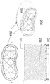
- Figure 1 presents a plan view (top left), a cross section (bottom left), and a perspective view (right) of this embodiment.
- the illustrated air filter element 100 comprises a filter medium pack 110 comprising a rolled-up length of filter medium.
- the filter medium pack 110 has a substantially planar first side 111 and a substantially planar second side 112, which are parallel to each other.
- the air filter element 100 is intended to be removably installed in a housing (not shown).
- the housing has one or more openings or "windows".
- Various housing and window arrangements are possible, including systems where the opening is accessed by removing the end of the housing where the inlet or the outlet is provided, and systems where a window on the side of the housing can be accessed.
- the "side loaders" may have their window on the narrow side or on the broad side.
- the present invention may be implemented with different kinds of filter media, including pleated filter media and fluted filter media.
- pleated filter media are commercially available and known to the skilled person.
- Fluted filter media includes filter material having a plurality of flutes formed therein having alternating ends of adjacent flutes closed to force fluid through filter material.
- Various types of fluted filter media are commercially available and known to the skilled person.
- a filter medium pack of the fluted filter media type or z-type media is known to the skilled person.
- some types of fluted filter media are known from US patent no. 3,025,963 to Jordan V. Bauer , US patent no. 5,895,574 to Francis Friedmann et al. , US patent no. 6,416,605 to Patrick Golden , and from US patent application publication no.
- a filter medium pack 110 of the fluted filter media type may for instance be obtained by rolling up a base sheet comprising generally parallel hollow tubes (flutes, original tubes) and applying a sealing adhesive between the consecutive layers of rolled-up filter medium, for instance at the side of the open ends.
- the base sheet can for instance be composed of a flat sheet of media and an undulated sheet of media, which are attached to each other.
- First axial ends of the hollow tubes are abutting a first substantially planar side 111 of the filter medium pack 110 and second axial ends of the hollow tubes are abutting a second substantially planar side 112 of the filter medium pack 110.
- Complementary spaces/tubes can be created in between the hollow tubes when rolling up the base sheets, and are being defined in between the undulated sheet of a certain winding and the flat sheet of its subsequent winding.
- the hollow tubes and the complementary spaces/tubes can be interrupted at appropriate locations such as to force air coming in in a first tube (e.g. an original tube) at its first axial end (at the first planar side 111) to pass through the sidewall of the first tube into one or more adjacent second tubes (e.g. complementary tube(s)), the air thereafter forcing to leave the second tube(s) at the second axial end of the second tube(s) (at the second planar side 112).
- Some of these interruptions may be provided initially with the original tubes (e.g. closed at their second axial end), others may be provided for instance by applying the sealing adhesive (e.g. for complementary tubes, preferably near their first axial ends).
- the ends 111, 112 then serve as outlet and inlet surfaces of the filter.
- air is supplied to the inlet surface, preferably but not necessarily, via a precleaning filter which may comprise a number of cyclones, and withdrawn from the outlet surface.
- a precleaning filter which may comprise a number of cyclones
- filter medium pack 110 may be obtained by including a step of rolling up a medium that is provided in the form of a sheet.
- the air filter element 100 further comprises a guiding rim 120 arranged on at least one of said first side 111 and said second side 112.
- guiding rims 120 are present on both sides 111, 112, as in the illustrated case.
- At least one such guiding rim 120 comprises a radially oriented sealing surface or a sealing surface having at least a radially oriented component.
- it may have an axial component. It may be provided with a gasket, acting as a radial seal or an axial seal with at least a radial component.
- Guiding rims 120 provide the sealing surface which allows the filter element 100 to sealingly engage with the inlet and/or outlet orifices of the filter system. In addition, they may contribute to the structural rigidity of the filter element 100, and they can assist the operator in correctly positioning the filter element 100 in the filter system (by virtue of their shape, and optionally by means of added guiding elements such as protrusions, grooves, tabs, and the like).
- the guiding rims 120 may comprise a rigid plastic material (which may for instance be a supporting structure) such as but not only polyethylene or polypropylene, with a separate seal or gasket made of for instance a suitable elastomer, or polyurethane arranged on their sealing surface.
- a rigid plastic material such as but not only polyethylene or polypropylene
- a separate seal or gasket made of for instance a suitable elastomer, or polyurethane arranged on their sealing surface.
- the guiding rims 120 may be made of a material that can serve as a seal, in particular a suitable elastomer such as polyurethane.
- Guiding rims 120 may be separately manufactured and attached to the filter medium pack 110, or they may be molded in place (i.e. overmolded onto the filter medium pack 110 ) if the melting and curing properties of the chosen material allow this.
- the air filter as seen in the plan view has an elongate shape.
- the circumference of each guiding rim 120 comprises at least one convex portion and at least one concave portion.
- the left-hand side and the right-hand side of the contour are convex (viewed from the outside of the filter element) while the top side and the bottom side of the contour (the longitudinal sides) comprise a concave central portion.
- the contour of the filter medium pack 110 (as seen in cross-section in any plane parallel to the planar sides 111, 112 ) corresponds to (i.e., it closely matches) the entire circumference of the guiding rim 120.
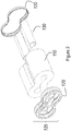
- FIG. 2 presents an exploded view of the filter element according to the first embodiment.
- the filter medium pack 110 has a tubular shape, i.e. its shape closes onto itself around a hollow center, and comprises a core 130 that is substantially geometrically similar to the outer contour of the filter medium pack 110.
- Figure 2 shows the guiding rims 120 on each side of the filter medium 110 and the core 130 to be placed at the center of the filter medium 110.
- the guiding rims may be comprised in an element 125 that covers part of the relevant side 111 or 112, for example to avoid telescopic deformation of the rolled up filter medium pack 110; to increase structural rigidity, the element 125 may also help to keep the core 130 in place.
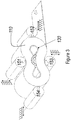
- Figure 3 schematically illustrates a first method of producing the filter element 100 according to the first embodiment.
- the method comprises rolling up a length of filter medium having a constant width, to produce a filter medium pack 110 with a substantially planar first side 111 and a substantially planar second side 112, the first side 111 and second side 112 being parallel.
- the rolling up comprises rolling the length of filter medium around a core 130 having a shape that is substantially geometrically similar to the desired circumference.
- the sheet is kept under appropriate tension and pressed onto the core 130 and subsequently onto the increasing pack by suitably arranged reciprocating rollers 151-154.
- Adhesive (not shown) is applied to the sheet to keep the consecutive layers together.
- a guiding rim 120 as described above is arranged on at least one of the first side 111 and the second side 112 (not illustrated in Figure 3 ).
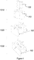
- Figure 4 schematically illustrates a second method of producing the filter element according to the first embodiment.
- a length of filter medium having a constant width is rolled up around an oval or obround winding core, to produce a filter medium pack 110 with a substantially planar first side 111 and a substantially planar second side 112, the first side 111 and second side 112 being parallel.
- the tensioning and pressing of the filter medium sheet is less complex than in the case illustrated in Figure 3 .
- adhesive is applied to the sheet to keep the consecutive layers together.
- the resulting filter medium pack 110 has an elongate shape without concave portions, and a hollow center.
- a core 130 that represents the desired contour shape by being substantially geometrically similar to it is inserted into the said hollow center of the filter medium pack 110.
- the filter medium pack 110 with the core 130 is placed into an appropriately shaped press-mold 160, which has protrusions corresponding to the desired concave portions of the contour.
- the press-mold 160 is closed to force the filter medium pack 110 into the desired shape. As this deformation inevitably causes some sliding of the layers of filter medium in the filter medium pack 110, this step should be completed before the applied adhesive has completely cured.
- a guiding rim 120 as described above is arranged on at least one of the first side 111 and the second side 112.
- Figure 5 presents a plan view (top left), a cross section (bottom left), and a perspective view (right) of this embodiment.
- the illustrated air filter element 100 comprises a filter medium pack 110 comprising two separately rolled-up lengths of filter medium.
- the resulting filter medium pack 110 has a substantially planar first side 111 and a substantially planar second side 112, which are parallel to each other.
- the filter medium is preferably of the "fluted filter media" type.
- the air filter element 100 further comprises a guiding rim 120 arranged on at least one of said first side 111 and said second side 112.
- guiding rims 120 are present on both sides 111, 112, as in the illustrated case.
- the illustrated filter medium pack 110 consists of two separately rolled-up lengths of filter medium
- the guiding rim 120 has the additional function of keeping these two rolls together to form one pack.
- the air filter element 100 has an elongate shape.
- the circumference of each guiding rim 120 comprises at least one convex portion and at least one concave portion.
- the left-hand side and the right-hand side of the contour are convex (viewed from the outside of the filter element) while the top side and the bottom side of the contour (the longitudinal sides) comprise a concave central portion.
- the contour of the filter medium pack 110 corresponds to (i.e., it closely matches) the convex portion of the circumference of the guiding rim 120.
- the concave portions are situated where the two rolls of media meet each other, the contour of the filter medium pack 110 does not strictly follow the circumference of the guiding rim 120 in these portions.
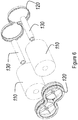
- FIG. 6 presents an exploded view of the filter element according to the second embodiment.
- the filter medium pack 110 consists of two tubular cylinders, i.e. cylinders with a hollow center, and comprises corresponding cylindrical cores 130.
- Figure 6 also shows the guiding rims 120 on each side of the filter medium 110 that keeps the rolls of filter medium 110 together and the cores 130 to be placed at the center of the rolls of filter medium 110.
- a third embodiment of the filter element according to the present invention will now be described with reference to Figures 7 and 8 .
- This embodiment will be described with emphasis on the elements that differ from those of the first embodiment.
- Figure 7 presents a plan view (top left), a cross section (bottom left), and a perspective view (right) of this embodiment.
- the illustrated air filter element 100 comprises a filter medium pack 110 comprising a rolled-up length of filter medium.
- the filter medium pack 110 has a substantially planar first side 111 and a substantially planar second side 112, which are parallel to each other.
- the filter medium is again preferably of the "fluted filter media" type.
- the air filter element 100 further comprises a guiding rim 120 arranged on at least one of said first side 111 and said second side 112.
- guiding rims 120 are present on both sides 111, 112, as in the illustrated case.
- the air filter element 100 has an elongate shape.
- the circumference of each guiding rim 120 comprises at least one convex portion and at least one concave portion.
- the left-hand side and the right-hand side of the contour are convex (viewed from the outside of the filter element) while the top side of the contour is straight and the bottom side of the contour comprises a concave central portion.
- the contour of the filter medium pack 110 corresponds to (i.e., it closely matches) the entire circumference of the guiding rim 120.
- FIG 8 presents an exploded view of the filter element according to the first embodiment.
- the filter medium pack 110 has a tubular shape, i.e. its shape closes onto itself around a hollow center, and comprises a core 130 that is substantially geometrically similar to the outer contour of the filter medium pack 110.
- Figure 8 shows the guiding rims 120 on each side of the filter medium 110 and the core 130 to be placed at the center of the filter medium 110.
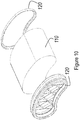
- a fourth embodiment of the filter element according to the present invention will now be described with reference to Figures 9-11 . This embodiment will be described with emphasis on the elements that differ from those of the first embodiment.
- Figure 9 presents a plan view (top left), a cross section (bottom left), and a perspective view (right) of this embodiment.
- the illustrated air filter element 100 comprises a filter medium pack 110 comprising a rolled-up length of filter medium.
- the filter medium pack 110 has a substantially planar first side 111 and a substantially planar second side 112, which are parallel to each other.
- the filter medium is again preferably of the "fluted filter media" type.
- the air filter element 100 further comprises a guiding rim 120 arranged on at least one of said first side 111 and said second side 112.
- guiding rims 120 are present on both sides 111, 112, as in the illustrated case.
- the air filter element 100 has an elongate shape.
- the circumference of each guiding rim 120 comprises at least one convex portion and at least one concave portion.
- the top side, the left-hand side, and the right-hand side of the contour are convex (viewed from the outside of the filter element) while the bottom side of the contour comprises a concave central portion.
- the contour of the filter medium pack 110 corresponds to (i.e., it closely matches) the entire circumference of the guiding rim 120.
- Figure 10 presents an exploded view of the filter element according to the first embodiment.
- the filter medium pack 110 is completely filled, i.e. it does not have a hollow center, and there is no core in this case.
- Figure 10 also shows the guiding rims 120 on each side of the filter medium 110.
- Figure 11 schematically illustrates a method of producing the filter element according to the fourth embodiment.
- a length of filter medium having a constant width is rolled up around a cylindrical winding core, to produce a filter medium pack 110 with a substantially planar first side 111 and a substantially planar second side 112, the first side 111 and second side 112 being parallel.
- the tensioning of the filter medium sheet is less complex than in the case illustrated in Figure 3 .
- adhesive is applied to the sheet to keep the consecutive layers together.
- the resulting filter medium pack 110 has a cylindrical shape without concave portions, and a hollow center.
- a first step 2010 the filter medium pack 110 with the hollow center is placed into an appropriately shaped press-mold 160, which has protrusions and cavities corresponding to the desired shape of the contour.
- a second step 2020 the press-mold 160, is closed to force the filter medium pack 110 into the desired shape. As this deformation inevitably causes some sliding of the layers of filter medium in the filter medium pack 110, this step should be completed before the applied adhesive has completely cured.
- a guiding rim 120 as described above is arranged on at least one of the first side 111 and the second side 112.
- Figure 12 presents two perspective views of an air filter system comprising an air filter element according to an embodiment of the present invention
- Figure 13 presents two further perspective views of the air filter element depicted in Figure 12
- the air filter element illustrated in Figures 12 and 13 has a coreless kidney-shaped or bean-shaped filter media pack 110.
- a guiding rim 120 with a sealing surface is provided at one end.
- a handle 170 is provided across a concave portion of the contour.
- a handle may be obtained very simply by providing a bar or strip of material that bridges a concave portion of the contour, such that it can easily be grasped by a human operator by slipping one's fingers in the cavity behind the handle.
- the handle may be flexible and attached after production of the filter element. It may for instance be glued on the outer side of the media pack or on an outer protection layer thereof in a/the concave portion.
- a further protection layer or envelope, also called shell, of the filter medium pack can be provided surrounding its radial outer surface.
- the protection layer or envelope can extend over a limited distance or over the whole length of the media pack, providing a rigid or more rigid housing of the media pack.
- This protection layer can be made of hard material such as plastic, or for instance out of a protective cardboard.
- the handle can also be formed integrally with the protection envelope.
- the protection envelope or shell can moreover be integrally formed with the guiding rim or a support structure comprised in the guiding rim.
Priority Applications (18)
| Application Number | Priority Date | Filing Date | Title |
|---|---|---|---|
| EP16195388.0A EP3311902B1 (de) | 2016-10-24 | 2016-10-24 | Luftfilterelement und verfahren zur herstellung davon |
| JP2019521401A JP6986558B2 (ja) | 2016-10-24 | 2017-10-24 | エアフィルタエレメント、およびそれを製造する方法 |
| MA046560A MA46560A (fr) | 2016-10-24 | 2017-10-24 | Élément de filtre à air et procédé de fabrication associé |
| CN201780065762.1A CN110167655B (zh) | 2016-10-24 | 2017-10-24 | 空气过滤元件及其制造方法 |
| KR1020197014438A KR102474482B1 (ko) | 2016-10-24 | 2017-10-24 | 에어 필터 요소 및 그 제조 방법 |
| EP17792274.7A EP3528927B1 (de) | 2016-10-24 | 2017-10-24 | Luftfilterelement und verfahren zur herstellung davon |
| PCT/US2017/058119 WO2018081148A1 (en) | 2016-10-24 | 2017-10-24 | Air filter element and method for producing same |
| RU2019115801A RU2741431C2 (ru) | 2016-10-24 | 2017-10-24 | Фильтрующий элемент для воздуха и способ его изготовления |
| MX2019004711A MX2019004711A (es) | 2016-10-24 | 2017-10-24 | Elemento de filtro de aire y metodo de produccion del mismo. |
| CN202210605515.9A CN114984690A (zh) | 2016-10-24 | 2017-10-24 | 空气过滤元件及其制造方法 |
| EP21175093.0A EP3978096B1 (de) | 2016-10-24 | 2017-10-24 | Luftfilterelement |
| AU2017347988A AU2017347988B2 (en) | 2016-10-24 | 2017-10-24 | Air filter element and method for producing same |
| US16/344,673 US11517844B2 (en) | 2016-10-24 | 2017-10-24 | Air filter element and method for producing same |
| MX2022016246A MX2022016246A (es) | 2016-10-24 | 2019-04-23 | Elemento de filtro de aire y metodo de produccion del mismo. |
| ZA2019/03095A ZA201903095B (en) | 2016-10-24 | 2019-05-17 | Air filter element and method for producing same |
| JP2021193536A JP7234336B2 (ja) | 2016-10-24 | 2021-11-29 | エアフィルタエレメント、およびそれを製造する方法 |
| US17/981,888 US20230145669A1 (en) | 2016-10-24 | 2022-11-07 | Air filter element and method for producing same |
| AU2023200151A AU2023200151A1 (en) | 2016-10-24 | 2023-01-12 | Air filter element |
Applications Claiming Priority (1)
| Application Number | Priority Date | Filing Date | Title |
|---|---|---|---|
| EP16195388.0A EP3311902B1 (de) | 2016-10-24 | 2016-10-24 | Luftfilterelement und verfahren zur herstellung davon |
Publications (2)
| Publication Number | Publication Date |
|---|---|
| EP3311902A1 true EP3311902A1 (de) | 2018-04-25 |
| EP3311902B1 EP3311902B1 (de) | 2020-06-24 |
Family
ID=57206067
Family Applications (3)
| Application Number | Title | Priority Date | Filing Date |
|---|---|---|---|
| EP16195388.0A Active EP3311902B1 (de) | 2016-10-24 | 2016-10-24 | Luftfilterelement und verfahren zur herstellung davon |
| EP17792274.7A Active EP3528927B1 (de) | 2016-10-24 | 2017-10-24 | Luftfilterelement und verfahren zur herstellung davon |
| EP21175093.0A Active EP3978096B1 (de) | 2016-10-24 | 2017-10-24 | Luftfilterelement |
Family Applications After (2)
| Application Number | Title | Priority Date | Filing Date |
|---|---|---|---|
| EP17792274.7A Active EP3528927B1 (de) | 2016-10-24 | 2017-10-24 | Luftfilterelement und verfahren zur herstellung davon |
| EP21175093.0A Active EP3978096B1 (de) | 2016-10-24 | 2017-10-24 | Luftfilterelement |
Country Status (11)
| Country | Link |
|---|---|
| US (2) | US11517844B2 (de) |
| EP (3) | EP3311902B1 (de) |
| JP (2) | JP6986558B2 (de) |
| KR (1) | KR102474482B1 (de) |
| CN (2) | CN114984690A (de) |
| AU (2) | AU2017347988B2 (de) |
| MA (1) | MA46560A (de) |
| MX (2) | MX2019004711A (de) |
| RU (1) | RU2741431C2 (de) |
| WO (1) | WO2018081148A1 (de) |
| ZA (1) | ZA201903095B (de) |
Cited By (2)
| Publication number | Priority date | Publication date | Assignee | Title |
|---|---|---|---|---|
| EP3881922A1 (de) * | 2020-03-19 | 2021-09-22 | Donaldson Company, Inc. | Filterelement mit dichtungsaufnahme |
| CN113727770A (zh) * | 2019-02-08 | 2021-11-30 | 唐纳森公司 | 过滤器密封组件和系统 |
Families Citing this family (9)
| Publication number | Priority date | Publication date | Assignee | Title |
|---|---|---|---|---|
| MX2020005694A (es) | 2017-12-08 | 2020-08-20 | Cummins Filtration Ip Inc | Sello ovalado con contorno de estabilizacion. |
| US10918978B2 (en) | 2018-05-08 | 2021-02-16 | Cummins Filtration Ip, Inc. | Oval filter with exterior elliptical radial seal and internal support structure |
| USD884866S1 (en) | 2018-05-08 | 2020-05-19 | Cummins Filtration Ip, Inc. | Filter element |
| US11124059B2 (en) * | 2018-10-29 | 2021-09-21 | K&N Engineering, Inc. | Multiple inlet filtration system |
| USD914839S1 (en) * | 2018-12-26 | 2021-03-30 | Strauss Water Ltd | Water filter |
| BR112022003160A2 (pt) * | 2019-08-23 | 2022-05-17 | Cummins Filtration Ip Inc | Conjuntos de filtro e elementos filtrantes que utilizam meios filtrantes multicamada e com envoltório |
| USD969289S1 (en) | 2020-03-05 | 2022-11-08 | Cummins Filtration Inc. | Filter element |
| US20230390687A1 (en) * | 2020-11-24 | 2023-12-07 | Cummins Filtration Inc. | Arched air filter |
| USD980402S1 (en) * | 2022-11-21 | 2023-03-07 | Ruiyun Li | Air filter |
Citations (9)
| Publication number | Priority date | Publication date | Assignee | Title |
|---|---|---|---|---|
| US3025963A (en) | 1958-03-13 | 1962-03-20 | Russell H Curtis | Products useful as filtering devices and methods of making them |
| US5895574A (en) | 1996-04-26 | 1999-04-20 | Donaldson Company, Inc. | Rolled liquid filter using fluted media |
| US6416605B1 (en) | 1999-11-24 | 2002-07-09 | Donaldson Company, Inc. | Method for manufacturing fluted media |
| EP1656982A1 (de) * | 2004-11-04 | 2006-05-17 | TELA S.r.l. | Verbundfiltermaterial |
| DE102011011595A1 (de) * | 2011-02-17 | 2012-08-23 | Mann + Hummel Gmbh | Filterelement |
| US20140102057A1 (en) | 2002-05-09 | 2014-04-17 | Donaldson Company, Inc. | Air filter having fluted filter media |
| US20150101299A1 (en) * | 2011-10-26 | 2015-04-16 | Donaldson Company, Inc. | Assemblies; components and filter features thereof; and, methods of use and assembly |
| DE102014016908A1 (de) * | 2013-11-20 | 2015-05-21 | Mann + Hummel Gmbh | Filterelement mit Filterbalg |
| DE102015016236A1 (de) * | 2015-01-23 | 2016-07-28 | Mann+Hummel Gmbh | Filterelement mit mehreren übereinanderliegenden Einzelblättern |
Family Cites Families (41)
| Publication number | Priority date | Publication date | Assignee | Title |
|---|---|---|---|---|
| US4211543A (en) * | 1978-04-24 | 1980-07-08 | Donaldson Company, Inc. | Air cleaner with replaceable filter element |
| JPS6174618A (ja) * | 1984-09-20 | 1986-04-16 | Matsushita Electric Works Ltd | 濾材 |
| DE3622955A1 (de) * | 1986-07-09 | 1988-01-21 | Sueddeutsche Kuehler Behr | Verfahren zur herstellung eines luftfilters |
| JPH01101618U (de) * | 1987-12-28 | 1989-07-07 | ||
| DE10024473B4 (de) | 2000-05-18 | 2007-04-19 | Vishay Semiconductor Gmbh | Optischer Empfänger |
| JP4388375B2 (ja) * | 2001-12-03 | 2009-12-24 | ドナルドソン カンパニー,インコーポレイティド | 波形の媒体シートを使用するフィルタエレメント |
| DE10309660A1 (de) | 2003-03-06 | 2004-09-16 | Tepcon Engineering Gesellschaft Mbh | Inline-Filter zur Abscheidung von Feststoffen aus einem Luftstrom |
| WO2005063361A1 (en) * | 2003-12-22 | 2005-07-14 | Donaldson Company, Inc. | Filter element comprising a seal arrangement and method for making the same |
| PL3470130T3 (pl) * | 2004-03-24 | 2022-01-17 | Donaldson Company, Inc. | Wkład filtra powietrza i układ oczyszczacza powietrza |
| AU2005240577B2 (en) * | 2004-04-30 | 2010-11-04 | Donaldson Company, Inc. | Filter arrangements; housings; assemblies; and, methods |
| EP2319600B1 (de) | 2004-06-08 | 2014-08-20 | Donaldson Company, Inc. | Z-Filtermedienpackungsanordnung und Verfahren |
| EP1781398B1 (de) * | 2004-07-20 | 2010-02-17 | Donaldson Company, Inc. | Z-filtermedienpackungsanordnung, filterpatrone, luftreinigungsvorrichtungsanordnung und verfahren |
| US8292983B2 (en) * | 2005-01-13 | 2012-10-23 | Donaldson Company, Inc. | Air filter cartridge and air cleaner assembly |
| CN101405068B (zh) | 2005-11-09 | 2011-09-14 | 唐纳森公司 | 过滤元件的密封结构;过滤元件组件和方法 |
| US7753982B2 (en) * | 2006-02-17 | 2010-07-13 | Baldwin Filters, Inc. | Filter with drained jacket, seal indicator/lock means, and seal baffle |
| KR20080019911A (ko) * | 2006-08-29 | 2008-03-05 | (주)로터스엔지니어링 | 공기정화장치 |
| US8292984B2 (en) * | 2007-07-20 | 2012-10-23 | Donaldson Company, Inc. | Air cleaner arrangments with end support for cartridge; components; and, methods |
| DE202007012690U1 (de) * | 2007-09-11 | 2009-02-05 | Mann+Hummel Gmbh | Filtereinrichtung |
| DE502008003057D1 (de) * | 2007-12-07 | 2011-05-12 | Mann & Hummel Gmbh | Filtereinrichtung zur filtration gasförmiger fluide, insbesondere luftfilter für brennkraftmaschinen |
| EP3351785A1 (de) | 2008-06-11 | 2018-07-25 | Mann+Hummel GmbH | Filtereinrichtung zur filtration gasförmiger fluide |
| US8048187B2 (en) | 2008-06-30 | 2011-11-01 | Baldwin Filters, Inc. | Filter frame attachment and fluted filter having same |
| CN201253524Y (zh) * | 2008-07-26 | 2009-06-10 | 蚌埠市昊业滤清器有限公司 | 蜂窝式空气滤清器滤芯 |
| MX2011001291A (es) * | 2008-08-06 | 2011-03-15 | Donaldson Co Inc | Metodos y aparatos de medios de filtracion-z que tienen acanalados cerrados. |
| US10293296B2 (en) * | 2008-08-15 | 2019-05-21 | MANN+HUMMEL Filtration Technology Group Inc. | Filter |
| US8506668B2 (en) * | 2009-03-30 | 2013-08-13 | Baldwin Filters, Inc. | Fluted filter with axial seal |
| US8187352B2 (en) * | 2009-09-21 | 2012-05-29 | Klaus Schumann | Filter |
| EP2482955B1 (de) | 2009-10-02 | 2013-08-28 | Donaldson Company, Inc. | Filterpatrone mit kielschwert und staubsammlern sowie entsprechende verfahren |
| KR200462402Y1 (ko) * | 2010-04-08 | 2012-09-10 | (주) 매직코리아 | 연료필터장치 |
| US9555346B2 (en) * | 2011-05-10 | 2017-01-31 | Cummins Filtration Ip Inc. | Filter with tri-flow path combinations |
| DE102011111378A1 (de) | 2011-08-29 | 2013-02-28 | Mann + Hummel Gmbh | Filterelement, Filteranordnung und Verfahren zum Herstellen des Filterelements |
| DE102012000470A1 (de) * | 2012-01-13 | 2013-07-18 | Mann + Hummel Gmbh | Luftfilterelement und Luftfilter |
| US9105361B2 (en) | 2012-10-31 | 2015-08-11 | Seagate Technology Llc | Fault tolerant control line configuration |
| FR2997868A1 (fr) | 2012-11-13 | 2014-05-16 | Mecaplast Sa | Procede de fabrication d'un filtre |
| US20140144111A1 (en) * | 2012-11-29 | 2014-05-29 | Donaldson Company Inc. | Filter cartridges; features and methods of assemlby; air cleaner assemblies; and, filter cartridge combinations |
| US10359011B2 (en) * | 2013-05-22 | 2019-07-23 | Donaldson Company, Inc. | Vertical air intake system; air cleaner; and filter element |
| US9421489B2 (en) * | 2013-06-24 | 2016-08-23 | Parker-Hannifin Corporation | Diesel fuel and urea tank air breather filter |
| DE112014003011T5 (de) * | 2013-06-28 | 2016-03-10 | Donaldson Company, Inc. | Filtereinsätze, Luftreinigeranordnungen, Gehäuse, Merkmale, Komponenten und Verfahren |
| US9441583B2 (en) * | 2014-06-03 | 2016-09-13 | Caterpillar Inc. | Air filter assembly for a machine |
| CN204522623U (zh) * | 2014-12-31 | 2015-08-05 | 四川蜀望生态环保科技有限公司 | 一种新型工业空气过滤装置 |
| TWI534006B (zh) | 2015-04-09 | 2016-05-21 | Filter element and its forming method | |
| CN105964059B (zh) | 2016-06-22 | 2018-01-19 | 东华大学 | 一种增能的聚乙烯/聚丙烯双组分纺粘滤料及其制备方法 |
-
2016
- 2016-10-24 EP EP16195388.0A patent/EP3311902B1/de active Active
-
2017
- 2017-10-24 WO PCT/US2017/058119 patent/WO2018081148A1/en active Application Filing
- 2017-10-24 KR KR1020197014438A patent/KR102474482B1/ko active IP Right Grant
- 2017-10-24 EP EP17792274.7A patent/EP3528927B1/de active Active
- 2017-10-24 MX MX2019004711A patent/MX2019004711A/es unknown
- 2017-10-24 JP JP2019521401A patent/JP6986558B2/ja active Active
- 2017-10-24 EP EP21175093.0A patent/EP3978096B1/de active Active
- 2017-10-24 MA MA046560A patent/MA46560A/fr unknown
- 2017-10-24 CN CN202210605515.9A patent/CN114984690A/zh active Pending
- 2017-10-24 AU AU2017347988A patent/AU2017347988B2/en active Active
- 2017-10-24 RU RU2019115801A patent/RU2741431C2/ru active
- 2017-10-24 US US16/344,673 patent/US11517844B2/en active Active
- 2017-10-24 CN CN201780065762.1A patent/CN110167655B/zh active Active
-
2019
- 2019-04-23 MX MX2022016246A patent/MX2022016246A/es unknown
- 2019-05-17 ZA ZA2019/03095A patent/ZA201903095B/en unknown
-
2021
- 2021-11-29 JP JP2021193536A patent/JP7234336B2/ja active Active
-
2022
- 2022-11-07 US US17/981,888 patent/US20230145669A1/en active Pending
-
2023
- 2023-01-12 AU AU2023200151A patent/AU2023200151A1/en active Pending
Patent Citations (11)
| Publication number | Priority date | Publication date | Assignee | Title |
|---|---|---|---|---|
| US3025963A (en) | 1958-03-13 | 1962-03-20 | Russell H Curtis | Products useful as filtering devices and methods of making them |
| US5895574A (en) | 1996-04-26 | 1999-04-20 | Donaldson Company, Inc. | Rolled liquid filter using fluted media |
| US6416605B1 (en) | 1999-11-24 | 2002-07-09 | Donaldson Company, Inc. | Method for manufacturing fluted media |
| US20140102057A1 (en) | 2002-05-09 | 2014-04-17 | Donaldson Company, Inc. | Air filter having fluted filter media |
| US9162172B2 (en) | 2002-05-09 | 2015-10-20 | Donaldson Company, Inc. | Air filter having fluted filter media |
| EP1656982A1 (de) * | 2004-11-04 | 2006-05-17 | TELA S.r.l. | Verbundfiltermaterial |
| DE102011011595A1 (de) * | 2011-02-17 | 2012-08-23 | Mann + Hummel Gmbh | Filterelement |
| US9205361B2 (en) | 2011-02-17 | 2015-12-08 | Mann + Hummel Gmbh | Air filter element, air filter housing and air filter system |
| US20150101299A1 (en) * | 2011-10-26 | 2015-04-16 | Donaldson Company, Inc. | Assemblies; components and filter features thereof; and, methods of use and assembly |
| DE102014016908A1 (de) * | 2013-11-20 | 2015-05-21 | Mann + Hummel Gmbh | Filterelement mit Filterbalg |
| DE102015016236A1 (de) * | 2015-01-23 | 2016-07-28 | Mann+Hummel Gmbh | Filterelement mit mehreren übereinanderliegenden Einzelblättern |
Cited By (3)
| Publication number | Priority date | Publication date | Assignee | Title |
|---|---|---|---|---|
| CN113727770A (zh) * | 2019-02-08 | 2021-11-30 | 唐纳森公司 | 过滤器密封组件和系统 |
| EP3881922A1 (de) * | 2020-03-19 | 2021-09-22 | Donaldson Company, Inc. | Filterelement mit dichtungsaufnahme |
| WO2021188967A1 (en) * | 2020-03-19 | 2021-09-23 | Donaldson Company, Inc. | Filter element with seal receiver |
Also Published As
| Publication number | Publication date |
|---|---|
| JP2019531894A (ja) | 2019-11-07 |
| EP3978096A1 (de) | 2022-04-06 |
| MA46560A (fr) | 2019-08-28 |
| WO2018081148A1 (en) | 2018-05-03 |
| AU2023200151A1 (en) | 2023-02-09 |
| RU2019115801A3 (de) | 2020-11-24 |
| RU2019115801A (ru) | 2020-11-24 |
| KR102474482B1 (ko) | 2022-12-06 |
| CN110167655A (zh) | 2019-08-23 |
| MX2019004711A (es) | 2019-06-06 |
| ZA201903095B (en) | 2020-01-29 |
| AU2017347988A1 (en) | 2019-05-16 |
| US20230145669A1 (en) | 2023-05-11 |
| EP3528927B1 (de) | 2021-06-02 |
| CN114984690A (zh) | 2022-09-02 |
| RU2741431C2 (ru) | 2021-01-26 |
| EP3311902B1 (de) | 2020-06-24 |
| KR20190065447A (ko) | 2019-06-11 |
| AU2017347988B2 (en) | 2022-10-13 |
| US20200054982A1 (en) | 2020-02-20 |
| JP7234336B2 (ja) | 2023-03-07 |
| MX2022016246A (es) | 2023-02-09 |
| JP2022033847A (ja) | 2022-03-02 |
| EP3528927A1 (de) | 2019-08-28 |
| EP3978096B1 (de) | 2023-06-21 |
| US11517844B2 (en) | 2022-12-06 |
| JP6986558B2 (ja) | 2021-12-22 |
| CN110167655B (zh) | 2022-07-01 |
Similar Documents
| Publication | Publication Date | Title |
|---|---|---|
| EP3311902B1 (de) | Luftfilterelement und verfahren zur herstellung davon | |
| RU2741961C2 (ru) | Фильтрующие элементы, воздухоочистительные узлы и способы применения и сборки | |
| JP5624602B2 (ja) | 軸方向のシールを有する溝付きのフィルタ | |
| EP2140923A2 (de) | Faltenfilter mit integriertem Rahmen | |
| EP2140922A2 (de) | Filterrahmenbefestigung und Faltenfilter mit dieser Befestigung | |
| EP3415218A1 (de) | Gefaltete filtriermedien mit konischen rillen | |
| EP3145611B1 (de) | Herstellung von filtermedien zur aufrechterhaltung des durchflusses durch einen sockenfilter | |
| EP2217346B1 (de) | Filterelement mit einem wickelkern mit einer in mindestens einer seite davon ausgebildeten druckentlastungskerbe | |
| AU1354800A (en) | Increased flow capacity filter | |
| US20190070531A1 (en) | Glue beaded media for pool and spa filter cartridges | |
| CN105711058A (zh) | 用于生产层状织物帘布层胶片的设备 | |
| EP2286890B1 (de) | Zusammenklappbarer Kern, Filter und Verfahren | |
| MX2011001744A (es) | Filtro. | |
| CN217830688U (zh) | 一种网体提香滚筒 | |
| JP4814341B2 (ja) | 支持体およびフィルター素子の製法 | |
| JP2010510043A6 (ja) | 支持体およびフィルター素子の製法 | |
| CN116194186A (zh) | 具有独特形状的过滤器组件 |
Legal Events
| Date | Code | Title | Description |
|---|---|---|---|
| PUAI | Public reference made under article 153(3) epc to a published international application that has entered the european phase |
Free format text: ORIGINAL CODE: 0009012 |
|
| STAA | Information on the status of an ep patent application or granted ep patent |
Free format text: STATUS: THE APPLICATION HAS BEEN PUBLISHED |
|
| AK | Designated contracting states |
Kind code of ref document: A1 Designated state(s): AL AT BE BG CH CY CZ DE DK EE ES FI FR GB GR HR HU IE IS IT LI LT LU LV MC MK MT NL NO PL PT RO RS SE SI SK SM TR |
|
| AX | Request for extension of the european patent |
Extension state: BA ME |
|
| STAA | Information on the status of an ep patent application or granted ep patent |
Free format text: STATUS: REQUEST FOR EXAMINATION WAS MADE |
|
| 17P | Request for examination filed |
Effective date: 20181025 |
|
| RBV | Designated contracting states (corrected) |
Designated state(s): AL AT BE BG CH CY CZ DE DK EE ES FI FR GB GR HR HU IE IS IT LI LT LU LV MC MK MT NL NO PL PT RO RS SE SI SK SM TR |
|
| GRAP | Despatch of communication of intention to grant a patent |
Free format text: ORIGINAL CODE: EPIDOSNIGR1 |
|
| STAA | Information on the status of an ep patent application or granted ep patent |
Free format text: STATUS: GRANT OF PATENT IS INTENDED |
|
| INTG | Intention to grant announced |
Effective date: 20200103 |
|
| GRAS | Grant fee paid |
Free format text: ORIGINAL CODE: EPIDOSNIGR3 |
|
| GRAA | (expected) grant |
Free format text: ORIGINAL CODE: 0009210 |
|
| STAA | Information on the status of an ep patent application or granted ep patent |
Free format text: STATUS: THE PATENT HAS BEEN GRANTED |
|
| AK | Designated contracting states |
Kind code of ref document: B1 Designated state(s): AL AT BE BG CH CY CZ DE DK EE ES FI FR GB GR HR HU IE IS IT LI LT LU LV MC MK MT NL NO PL PT RO RS SE SI SK SM TR |
|
| REG | Reference to a national code |
Ref country code: GB Ref legal event code: FG4D |
|
| REG | Reference to a national code |
Ref country code: CH Ref legal event code: EP |
|
| REG | Reference to a national code |
Ref country code: DE Ref legal event code: R096 Ref document number: 602016038607 Country of ref document: DE |
|
| REG | Reference to a national code |
Ref country code: AT Ref legal event code: REF Ref document number: 1283335 Country of ref document: AT Kind code of ref document: T Effective date: 20200715 |
|
| REG | Reference to a national code |
Ref country code: IE Ref legal event code: FG4D |
|
| PG25 | Lapsed in a contracting state [announced via postgrant information from national office to epo] |
Ref country code: LT Free format text: LAPSE BECAUSE OF FAILURE TO SUBMIT A TRANSLATION OF THE DESCRIPTION OR TO PAY THE FEE WITHIN THE PRESCRIBED TIME-LIMIT Effective date: 20200624 Ref country code: GR Free format text: LAPSE BECAUSE OF FAILURE TO SUBMIT A TRANSLATION OF THE DESCRIPTION OR TO PAY THE FEE WITHIN THE PRESCRIBED TIME-LIMIT Effective date: 20200925 Ref country code: FI Free format text: LAPSE BECAUSE OF FAILURE TO SUBMIT A TRANSLATION OF THE DESCRIPTION OR TO PAY THE FEE WITHIN THE PRESCRIBED TIME-LIMIT Effective date: 20200624 Ref country code: SE Free format text: LAPSE BECAUSE OF FAILURE TO SUBMIT A TRANSLATION OF THE DESCRIPTION OR TO PAY THE FEE WITHIN THE PRESCRIBED TIME-LIMIT Effective date: 20200624 Ref country code: NO Free format text: LAPSE BECAUSE OF FAILURE TO SUBMIT A TRANSLATION OF THE DESCRIPTION OR TO PAY THE FEE WITHIN THE PRESCRIBED TIME-LIMIT Effective date: 20200924 |
|
| REG | Reference to a national code |
Ref country code: LT Ref legal event code: MG4D |
|
| PG25 | Lapsed in a contracting state [announced via postgrant information from national office to epo] |
Ref country code: LV Free format text: LAPSE BECAUSE OF FAILURE TO SUBMIT A TRANSLATION OF THE DESCRIPTION OR TO PAY THE FEE WITHIN THE PRESCRIBED TIME-LIMIT Effective date: 20200624 Ref country code: RS Free format text: LAPSE BECAUSE OF FAILURE TO SUBMIT A TRANSLATION OF THE DESCRIPTION OR TO PAY THE FEE WITHIN THE PRESCRIBED TIME-LIMIT Effective date: 20200624 Ref country code: BG Free format text: LAPSE BECAUSE OF FAILURE TO SUBMIT A TRANSLATION OF THE DESCRIPTION OR TO PAY THE FEE WITHIN THE PRESCRIBED TIME-LIMIT Effective date: 20200924 Ref country code: HR Free format text: LAPSE BECAUSE OF FAILURE TO SUBMIT A TRANSLATION OF THE DESCRIPTION OR TO PAY THE FEE WITHIN THE PRESCRIBED TIME-LIMIT Effective date: 20200624 |
|
| REG | Reference to a national code |
Ref country code: NL Ref legal event code: MP Effective date: 20200624 |
|
| REG | Reference to a national code |
Ref country code: AT Ref legal event code: MK05 Ref document number: 1283335 Country of ref document: AT Kind code of ref document: T Effective date: 20200624 |
|
| PG25 | Lapsed in a contracting state [announced via postgrant information from national office to epo] |
Ref country code: AL Free format text: LAPSE BECAUSE OF FAILURE TO SUBMIT A TRANSLATION OF THE DESCRIPTION OR TO PAY THE FEE WITHIN THE PRESCRIBED TIME-LIMIT Effective date: 20200624 Ref country code: NL Free format text: LAPSE BECAUSE OF FAILURE TO SUBMIT A TRANSLATION OF THE DESCRIPTION OR TO PAY THE FEE WITHIN THE PRESCRIBED TIME-LIMIT Effective date: 20200624 |
|
| PG25 | Lapsed in a contracting state [announced via postgrant information from national office to epo] |
Ref country code: CZ Free format text: LAPSE BECAUSE OF FAILURE TO SUBMIT A TRANSLATION OF THE DESCRIPTION OR TO PAY THE FEE WITHIN THE PRESCRIBED TIME-LIMIT Effective date: 20200624 Ref country code: PT Free format text: LAPSE BECAUSE OF FAILURE TO SUBMIT A TRANSLATION OF THE DESCRIPTION OR TO PAY THE FEE WITHIN THE PRESCRIBED TIME-LIMIT Effective date: 20201026 Ref country code: IT Free format text: LAPSE BECAUSE OF FAILURE TO SUBMIT A TRANSLATION OF THE DESCRIPTION OR TO PAY THE FEE WITHIN THE PRESCRIBED TIME-LIMIT Effective date: 20200624 Ref country code: ES Free format text: LAPSE BECAUSE OF FAILURE TO SUBMIT A TRANSLATION OF THE DESCRIPTION OR TO PAY THE FEE WITHIN THE PRESCRIBED TIME-LIMIT Effective date: 20200624 Ref country code: RO Free format text: LAPSE BECAUSE OF FAILURE TO SUBMIT A TRANSLATION OF THE DESCRIPTION OR TO PAY THE FEE WITHIN THE PRESCRIBED TIME-LIMIT Effective date: 20200624 Ref country code: AT Free format text: LAPSE BECAUSE OF FAILURE TO SUBMIT A TRANSLATION OF THE DESCRIPTION OR TO PAY THE FEE WITHIN THE PRESCRIBED TIME-LIMIT Effective date: 20200624 Ref country code: EE Free format text: LAPSE BECAUSE OF FAILURE TO SUBMIT A TRANSLATION OF THE DESCRIPTION OR TO PAY THE FEE WITHIN THE PRESCRIBED TIME-LIMIT Effective date: 20200624 Ref country code: SM Free format text: LAPSE BECAUSE OF FAILURE TO SUBMIT A TRANSLATION OF THE DESCRIPTION OR TO PAY THE FEE WITHIN THE PRESCRIBED TIME-LIMIT Effective date: 20200624 |
|
| PG25 | Lapsed in a contracting state [announced via postgrant information from national office to epo] |
Ref country code: SK Free format text: LAPSE BECAUSE OF FAILURE TO SUBMIT A TRANSLATION OF THE DESCRIPTION OR TO PAY THE FEE WITHIN THE PRESCRIBED TIME-LIMIT Effective date: 20200624 Ref country code: PL Free format text: LAPSE BECAUSE OF FAILURE TO SUBMIT A TRANSLATION OF THE DESCRIPTION OR TO PAY THE FEE WITHIN THE PRESCRIBED TIME-LIMIT Effective date: 20200624 Ref country code: IS Free format text: LAPSE BECAUSE OF FAILURE TO SUBMIT A TRANSLATION OF THE DESCRIPTION OR TO PAY THE FEE WITHIN THE PRESCRIBED TIME-LIMIT Effective date: 20201024 |
|
| REG | Reference to a national code |
Ref country code: DE Ref legal event code: R097 Ref document number: 602016038607 Country of ref document: DE |
|
| PG25 | Lapsed in a contracting state [announced via postgrant information from national office to epo] |
Ref country code: DK Free format text: LAPSE BECAUSE OF FAILURE TO SUBMIT A TRANSLATION OF THE DESCRIPTION OR TO PAY THE FEE WITHIN THE PRESCRIBED TIME-LIMIT Effective date: 20200624 |
|
| PLBE | No opposition filed within time limit |
Free format text: ORIGINAL CODE: 0009261 |
|
| STAA | Information on the status of an ep patent application or granted ep patent |
Free format text: STATUS: NO OPPOSITION FILED WITHIN TIME LIMIT |
|
| REG | Reference to a national code |
Ref country code: CH Ref legal event code: PL |
|
| 26N | No opposition filed |
Effective date: 20210325 |
|
| PG25 | Lapsed in a contracting state [announced via postgrant information from national office to epo] |
Ref country code: LU Free format text: LAPSE BECAUSE OF NON-PAYMENT OF DUE FEES Effective date: 20201024 Ref country code: MC Free format text: LAPSE BECAUSE OF FAILURE TO SUBMIT A TRANSLATION OF THE DESCRIPTION OR TO PAY THE FEE WITHIN THE PRESCRIBED TIME-LIMIT Effective date: 20200624 |
|
| REG | Reference to a national code |
Ref country code: BE Ref legal event code: MM Effective date: 20201031 |
|
| PG25 | Lapsed in a contracting state [announced via postgrant information from national office to epo] |
Ref country code: LI Free format text: LAPSE BECAUSE OF NON-PAYMENT OF DUE FEES Effective date: 20201031 Ref country code: SI Free format text: LAPSE BECAUSE OF FAILURE TO SUBMIT A TRANSLATION OF THE DESCRIPTION OR TO PAY THE FEE WITHIN THE PRESCRIBED TIME-LIMIT Effective date: 20200624 Ref country code: BE Free format text: LAPSE BECAUSE OF NON-PAYMENT OF DUE FEES Effective date: 20201031 Ref country code: CH Free format text: LAPSE BECAUSE OF NON-PAYMENT OF DUE FEES Effective date: 20201031 |
|
| PG25 | Lapsed in a contracting state [announced via postgrant information from national office to epo] |
Ref country code: IE Free format text: LAPSE BECAUSE OF NON-PAYMENT OF DUE FEES Effective date: 20201024 |
|
| PG25 | Lapsed in a contracting state [announced via postgrant information from national office to epo] |
Ref country code: TR Free format text: LAPSE BECAUSE OF FAILURE TO SUBMIT A TRANSLATION OF THE DESCRIPTION OR TO PAY THE FEE WITHIN THE PRESCRIBED TIME-LIMIT Effective date: 20200624 Ref country code: MT Free format text: LAPSE BECAUSE OF FAILURE TO SUBMIT A TRANSLATION OF THE DESCRIPTION OR TO PAY THE FEE WITHIN THE PRESCRIBED TIME-LIMIT Effective date: 20200624 Ref country code: CY Free format text: LAPSE BECAUSE OF FAILURE TO SUBMIT A TRANSLATION OF THE DESCRIPTION OR TO PAY THE FEE WITHIN THE PRESCRIBED TIME-LIMIT Effective date: 20200624 |
|
| PG25 | Lapsed in a contracting state [announced via postgrant information from national office to epo] |
Ref country code: MK Free format text: LAPSE BECAUSE OF FAILURE TO SUBMIT A TRANSLATION OF THE DESCRIPTION OR TO PAY THE FEE WITHIN THE PRESCRIBED TIME-LIMIT Effective date: 20200624 |
|
| P01 | Opt-out of the competence of the unified patent court (upc) registered |
Effective date: 20230413 |
|
| PGFP | Annual fee paid to national office [announced via postgrant information from national office to epo] |
Ref country code: GB Payment date: 20230920 Year of fee payment: 8 |
|
| PGFP | Annual fee paid to national office [announced via postgrant information from national office to epo] |
Ref country code: FR Payment date: 20230920 Year of fee payment: 8 |
|
| PGFP | Annual fee paid to national office [announced via postgrant information from national office to epo] |
Ref country code: DE Payment date: 20230920 Year of fee payment: 8 |