EP3311651A2 - Dreschwerk für einen mähdrescher und mähdrescher mit dem dreschwerk - Google Patents
Dreschwerk für einen mähdrescher und mähdrescher mit dem dreschwerk Download PDFInfo
- Publication number
- EP3311651A2 EP3311651A2 EP17001100.1A EP17001100A EP3311651A2 EP 3311651 A2 EP3311651 A2 EP 3311651A2 EP 17001100 A EP17001100 A EP 17001100A EP 3311651 A2 EP3311651 A2 EP 3311651A2
- Authority
- EP
- European Patent Office
- Prior art keywords
- threshing
- drum
- drums
- basket
- distance
- Prior art date
- Legal status (The legal status is an assumption and is not a legal conclusion. Google has not performed a legal analysis and makes no representation as to the accuracy of the status listed.)
- Granted
Links
- 238000000034 method Methods 0.000 claims abstract description 9
- 238000012545 processing Methods 0.000 claims abstract description 4
- 238000000926 separation method Methods 0.000 claims description 53
- 238000003306 harvesting Methods 0.000 claims description 11
- 230000000630 rising effect Effects 0.000 claims description 6
- 241000251169 Alopias vulpinus Species 0.000 claims description 5
- 235000013339 cereals Nutrition 0.000 description 27
- 239000010902 straw Substances 0.000 description 13
- 230000008021 deposition Effects 0.000 description 8
- 239000000463 material Substances 0.000 description 7
- 238000012805 post-processing Methods 0.000 description 7
- 235000013399 edible fruits Nutrition 0.000 description 6
- 238000004140 cleaning Methods 0.000 description 5
- 230000007704 transition Effects 0.000 description 5
- 240000006829 Ficus sundaica Species 0.000 description 4
- 230000001419 dependent effect Effects 0.000 description 4
- 240000008042 Zea mays Species 0.000 description 3
- 235000005824 Zea mays ssp. parviglumis Nutrition 0.000 description 3
- 235000002017 Zea mays subsp mays Nutrition 0.000 description 3
- 238000006243 chemical reaction Methods 0.000 description 3
- 235000005822 corn Nutrition 0.000 description 3
- 230000000694 effects Effects 0.000 description 3
- 230000002093 peripheral effect Effects 0.000 description 3
- 238000011144 upstream manufacturing Methods 0.000 description 3
- 244000046052 Phaseolus vulgaris Species 0.000 description 1
- 235000010627 Phaseolus vulgaris Nutrition 0.000 description 1
- 235000007264 Triticum durum Nutrition 0.000 description 1
- 241000209143 Triticum turgidum subsp. durum Species 0.000 description 1
- 230000001174 ascending effect Effects 0.000 description 1
- 238000006073 displacement reaction Methods 0.000 description 1
- 238000005265 energy consumption Methods 0.000 description 1
- 239000000446 fuel Substances 0.000 description 1
- 239000004615 ingredient Substances 0.000 description 1
- 238000003860 storage Methods 0.000 description 1
- 230000001360 synchronised effect Effects 0.000 description 1
Images


Classifications
-
- A—HUMAN NECESSITIES
- A01—AGRICULTURE; FORESTRY; ANIMAL HUSBANDRY; HUNTING; TRAPPING; FISHING
- A01F—PROCESSING OF HARVESTED PRODUCE; HAY OR STRAW PRESSES; DEVICES FOR STORING AGRICULTURAL OR HORTICULTURAL PRODUCE
- A01F7/00—Threshing apparatus
- A01F7/02—Threshing apparatus with rotating tools
- A01F7/04—Threshing apparatus with rotating tools with axles transverse to the feeding direction
-
- A—HUMAN NECESSITIES
- A01—AGRICULTURE; FORESTRY; ANIMAL HUSBANDRY; HUNTING; TRAPPING; FISHING
- A01F—PROCESSING OF HARVESTED PRODUCE; HAY OR STRAW PRESSES; DEVICES FOR STORING AGRICULTURAL OR HORTICULTURAL PRODUCE
- A01F12/00—Parts or details of threshing apparatus
- A01F12/18—Threshing devices
- A01F12/182—Stripper beaters after the threshing drum
-
- A—HUMAN NECESSITIES
- A01—AGRICULTURE; FORESTRY; ANIMAL HUSBANDRY; HUNTING; TRAPPING; FISHING
- A01F—PROCESSING OF HARVESTED PRODUCE; HAY OR STRAW PRESSES; DEVICES FOR STORING AGRICULTURAL OR HORTICULTURAL PRODUCE
- A01F12/00—Parts or details of threshing apparatus
- A01F12/18—Threshing devices
- A01F12/28—Devices for adjusting the concaves
-
- A—HUMAN NECESSITIES
- A01—AGRICULTURE; FORESTRY; ANIMAL HUSBANDRY; HUNTING; TRAPPING; FISHING
- A01F—PROCESSING OF HARVESTED PRODUCE; HAY OR STRAW PRESSES; DEVICES FOR STORING AGRICULTURAL OR HORTICULTURAL PRODUCE
- A01F12/00—Parts or details of threshing apparatus
- A01F12/10—Feeders
-
- A—HUMAN NECESSITIES
- A01—AGRICULTURE; FORESTRY; ANIMAL HUSBANDRY; HUNTING; TRAPPING; FISHING
- A01F—PROCESSING OF HARVESTED PRODUCE; HAY OR STRAW PRESSES; DEVICES FOR STORING AGRICULTURAL OR HORTICULTURAL PRODUCE
- A01F12/00—Parts or details of threshing apparatus
- A01F12/58—Control devices; Brakes; Bearings
Definitions
- the present invention relates to a threshing unit for a combine harvester, comprising at least three drums provided for processing the crop, comprising a threshing drum provided for threshing the crop, and at least two of the threshing drum in a conveying direction of the crop by the threshing subsequent drums.
- the present invention further relates to a combine harvester with such a threshing mechanism and to a method for adjusting the threshing unit.
- the threshing mechanism it is still necessary for the threshing mechanism to be adjustable depending on the crop type, the harvesting conditions and the desired threshing result. For a distance of the threshing drums at least partially encircling threshers and / or a peripheral speed of the threshing drums are changed. A close spacing leads to a sharper threshing process, but can cause a large amount of grain breakage and reduce straw quality. On the other hand, a long distance leads to reduced expression. In addition, a large difference in the threshing cylinder speeds possibly leads to increased grain breakage.
- the publication DE 10 2013 100 057 A1 deals with the adjustment of two threshing baskets, the two arranged in the conveying direction of the crop in a row Partially wrap around threshing drums in their circumferential direction.
- the concaves are mounted on angle levers which are pivotable about stationary axes.
- the angle levers are connected to each other by means of connecting rods and with a hydraulic cylinder. By adjusting the hydraulic cylinder they are shifted so that the angle levers pivot about their axes. As a result, the concaves are adjusted radially to the threshing drum.
- the arrangement allows a uniform adjustment of the concaves, through which the distance of the threshing drums to the Dresohkörben is approximately constant.
- Dreatke are also known with a threshing drum to which the crop is fed directly from the feeder, and a separating drum which increases the separation efficiency and which is arranged downstream of the threshing drum.
- the concave is usually very high in the conveying direction behind the threshing cylinder and passed the crop over a turning drum, which removes the crop from the threshing drum, in the separation drum.
- Such threshers show, for example, the publications DE 42 18 611 C3 and DE 10 2007 031 807 A1 ,
- a disadvantage of these threshing weights is that the crop has to be strongly deflected. Because this can worsen the straw quality and lead to increased grain breakage. In addition, the crop has to be re-accelerated at each strong deflection, which increases the power required to drive the threshing unit, as well as the energy consumption of the combine harvester.
- Object of the present invention is to provide a threshing for a particular self-propelled combine harvester which allows a very high separation efficiency with low grain breakage and good straw quality even with a large amount optionally uneven In the Dresohwerk supplied crop, and also requires the smallest possible drive power ,
- the threshing unit has at least three drums provided for processing the crop, which comprise a threshing drum provided for threshing the crop.
- the other two drums are considered downstream of the threshing drum in a conveying direction of the crop by the threshing.
- the large threshing drum Due to the large threshing drum, a sufficiently large threshing path is ensured which enables a very high separation.
- the large threshing drum also enables a very large harvesting throughput.
- the storage of the drums on the concave, rising fictitious line and the successively smaller diameter of the drums allow despite the large threshing drum a material flow course without strong Gutumlenkung, especially in the transition from the threshing drum to your immediately downstream drum. The crop stream is therefore not disturbed again and again but runs very evenly, and the crop does not have to be accelerated again and again.
- the large drums, especially the threshing drum the drive power required to drive the threshing unit is therefore sufficiently small.
- the diameter of the threshing drum is preferably as large as possible. It is mainly limited by the height of the combine harvester. Preferably it is about equal to or greater than 500mm, more preferably it is about equal to or greater than 600mm, most preferably it is about equal to or greater than 700mm. Even with a relatively small looping of the threshing drum through the concave so a large threshing path can be ensured. The threshing mechanism therefore allows a sufficiently high separation.
- the threshing drum is preferably a Vorreschen and / or for the promotion of the crop provided feed drum upstream in the conveying direction.
- the threshing mechanism has at least four drums.
- the feeding drum leads to equalizing the crop flow, even in the case of a large, in particular uneven, quantity of crop being fed.
- it accelerates the crop, so that this passes through the threshing with increased kinetic energy. Due to the relatively low Gutumlenkung this has an advantageous effect on the required drive power.
- the accelerated supply of the crop into the threshing cylinder, as well as an optional additional separating surface, which optionally interacts with the feed drum enables a further increased separation.
- a diameter of the feed drum is preferably smaller than that of the threshing drum. Preferably, it has a diameter that is greater than or equal to about 400mm to ensure uniform crop flow. It is further preferred that your peripheral speed be less than that of the threshing drum to slowly accelerate the crop.
- the feed drum is mounted on the fictitious line.
- the crop in the area of the transition of the feed drum to the threshing drum can be specifically deflected more strongly. This improves the expression.
- the threshing element can be adjusted depending on crop conditions and / or manually or automatically depending on the harvesting conditions, for example moisture-dependent.
- the drums downstream drums preferably comprise a separation drum.
- the separation drum is provided to further increase the deposition.
- the skiving drum is particularly preferably arranged downstream of the threshing drum in the conveying direction.
- the diameter of the separation drum is greater than 350mm, more preferably greater than 500mm. Due to the comparison with the threshing drum smaller diameter of the separating drum and the concave extending in the conveying direction rising fictitious line on which the drums are mounted, which is Good deflection Low in the transition area between the threshing drum and the separating drum. Overall, however, a large separation drum, which allows a large separation area, can be used.
- the drums following drums comprise a turning drum, which is downstream of the separation drum in the conveying direction, in particular directly.
- the turning drum picks up the crop from the separating drum. It is intended for conveying and / or deflecting the crop. Also grains or fruits are being separated.
- the turning drum preferably directs the crop to a post-processing device for the crop, in particular to a tray shaker. Due to the large drum diameter, it is advantageous to use the turning drum for guiding the crop to the post-processing device.
- the diameter of the turning drum is preferably greater than 250mm, more preferably greater than 300mm. According to the invention, it is also smaller than the separation drum in order not to disturb the material flow unnecessarily. The small diameter of the turning drum is sufficient for guiding the crop. In addition, the turning drum thereby has a low weight, which has an advantageous effect on the drive power required for the threshing unit.
- the diameter of the drums in particular the threshing drum and the two downstream separating drum and turning drum, are coordinated so that the grain breakage is minimized.
- the separation drum is not more than 40% smaller than the threshing cylinder, more preferably not more than 30% smaller.
- the rotational speeds of all the drums of the threshing unit are adjusted synchronously, which is fixed in relation to each other. This can be ensured even when adjusting the speed that the grain breakage is low. In addition, this is advantageous in terms of the uniform crop flow, the level of deposition and the straw quality. In addition, the speed of the separation drum is adjusted automatically. A manual conversion of the rotational speeds of the drums on different types of crops, for example of corn on corn, is eliminated.
- the operation of the threshing mechanism is therefore very easy for the user and the possibility of a Fehibedienung the threshing unit is so low.
- the threshing mechanism comprises a concave and a separating basket.
- the concave preferably surrounds at least the threshing drum, or, if the threshing mechanism has a feed drum, the feed drum and the threshing drum, in each case at least partially in their circumferential directions.
- the threshing drum, or the feed drum and the threshing drum cooperate with the concave.
- the thresher basket can also be made in multiple layers.
- the threshing mechanism preferably comprises the separation basket, which surrounds the separation drum at least partially in its circumferential direction. Upon deposition, the skimmer basket and the separation drum act together.
- the concave and the separating basket are preferably connected to each other so that they are adjustable together.
- this measure simplifies the operation of the threshing for the user.
- the threshing mechanism has a basket adjustment, which is provided for adjusting the threshing concave and the separating basket.
- the basket adjustment preferably has a first adjusting lever, in particular a hydraulic motor or an adjusting lever driven by an electric motor. Additionally or alternatively, a manually operable lever may be provided.
- a threshing concave position of the concave that is a distance of the threshing drum from the concave
- a Abscheidekorbposition the Abscheidekorbes that is a distance of the Abscheldetrommel from Abscheidekorb, depending on the concave position adjusted unequal. It is further preferred that when adjusting the threshing basket and the separating basket of Abscheidekorb at a narrow concave position, ie a small distance of the threshing drum from the concave, is less strongly adjusted, as in a worlds concave position, ie a large distance of the threshing drum from the concave.
- the narrow concave position is advantageous for example for cereals, the wide concave position for corn or beans. Also, the manual conversion of the concealer position and / or the Abscheidekorbposition Depending on the Erntegutart, for example, the conversion of grain to Mals, therefore eliminated. The operation of the threshing unit is thus further simplified for the user.
- the separating basket position can be preset.
- a distance of the separating basket from the separating drum can be preset.
- a narrow distance or a further distance of the separating basket from the separating drum independently of the distance of the threshing basket from the threshing cylinder, or the threshing basket from the feed drum and the threshing drum, can be preset.
- the distance of the separating basket from the separating drum is continuously variable.
- the basket adjustment therefore allows depending on the desired threshing the choice between a particularly large separation and a particularly good straw quality.
- the threshing unit on the basket adjustment in addition to a Dreschkorbver ein for adjusting the distance of the concave of the Dreschtrommel, or from the feed drum and the threshing drum, a Abscheidukorbver ein, wherein the Abborgekorbver ein is provided for adjusting the distance of the Abscheidekorbes of the Abscheidermommel.
- the Abscheidekorberwolf and the concave adjustment are preferably connected to each other with a connecting member which is displaceable by means of a shaft rotatable about the axis of rotation eccentrically.
- the separating basket adjustment preferably has a second adjusting lever.
- the adjusting lever is in two Adjustable positions.
- the shaft is rotated by a rotation angle in one direction of rotation, in particular by about 180 °.
- the separation basket is at least adjustable into a narrow separation basket position, in which its distance from the separation drum is small, and into a wide separation basket position, in which its distance from the separation drum is greater than in the narrow separation basket position.
- the adjusting lever is continuously adjustable, so that the Abscheidekorbposition is continuously adjustable.
- the separation basket adjustment preferably has a hydromotor or an electromotive drive. Additionally or alternatively, a manual adjustment may be provided.
- the separating basket is opened wide in the event of a narrow concave position when adjusting from the narrow to the wide separating basket position.
- the adjustability of the Abscheidekorbposition is therefore limited, especially at maximum concave position.
- the drums of the threshing unit and its dimensions are coordinated so that they allow a very good separation and a very good straw Quailt decisiv with little grain breakage. Nevertheless, the drive power required to drive the threshing unit is sufficiently small.
- the object is further achieved with a combine harvester with such a threshing unit.
- the combine harvester is designed for high crop throughput. It preferably has a Nachabschelde adopted, preferably a Horden presentler, which is downstream of the threshing unit. In the Horde Shaker, non-grain ingredients such as chaff and straw are separated from the grains or fruits.
- the combine comprises a control unit which is set up to jointly adjust the rotational speeds of the drums and / or the distances of the drums of the threshing mechanism from the baskets of the threshing unit.
- the rotational speeds of the drums are synchronized, that is, in a fixed relationship to each other, adjusted.
- the control unit is set up for presetting the deposition basket position.
- the combine harvester has a user interface which makes it possible to set the rotational speed of the threshing drum, the concave position and / or the presetting of the separating basket position.
- the control unit is provided for automatically adjusting the rotational speeds of the remaining drums and / or the basket positions as a function of the speed of the threshing drum, the concave position and / or the presetting of the separating basket position.
- a setting of the speed of the threshing drum, the concave position and / or the default setting of the Abscheidekorbposition from the driver's cab is possible.
- the user interface has a display unit, on which the current speed of the threshing drum, the current concave position and / or the current default of the Abscheidekorbposition is displayed.
- the current deposition, the current grain breakage and / or the current straw quality are particularly preferably displayed on the display unit. Due to this feedback, the operator can make an optimal adjustment of the threshing unit during the harvesting operation.
- the method also provides, in particular subsequently, that the rotational speeds of the drums of the threshing unit, in particular as a function of the type of crop and / or the harvesting conditions, are adjusted synchronously in a fixed relationship to each other.
- the adjustment of the rotational speeds of the drums and / or the distances of the drums from the baskets can be carried out independently of one another or in dependence on one another.
- the threshing in particular crop-dependent and / or depending on the harvesting conditions, automatically adjusted optimally.
- the operator can be relieved and erroneous operations can be avoided.
- FIG. 1 shows a self-propelled agricultural harvester 2, here a combine harvester.
- the terms combine harvester and self-propelled agricultural harvester 2 are used interchangeably below.
- a direction of travel of the combine harvester 2 is shown by an arrow FR.
- the combine harvester 2 has a front side 21 on which a driver's cab 50 for an operator 55 is arranged.
- a cutting unit 7 is arranged on the front side 21, which receives crop 3.
- the cutter 7 directs the crop 3 to a feeder 6, via which it is passed as a flow 33 in a conveying direction 30 to a threshing 1.
- the conventional threshing unit 1 shown here has three drums 11-13, namely a pre-shredding drum 11, which is upstream of a threshing drum 12, the threshing cylinder 12 and a deflection drum 13 downstream of the threshing drum 12.
- the pre-shredding drum is used for pre-threshing the crop 3 and for feeding the crop Harvest material 3 provided to the threshing cylinder 12, the threshing drum 12 threshes the crop 3, and the guide drum 13 passes the crop 3 a post-processing device 4, here a Horden presentler, which is provided for cleaning the crop 3.
- a post-processing device 4 and Horde shakers are used synonymously below.
- a concave 15 is arranged, is deposited by the already dissolved grain from the Erntegutstrom 33.
- the grains separated in the threshing unit 1 and the post-processing device 4 are fed via a return bottom 42 and a feed bottom 41 to a cleaning device 43 (not designated) comprising a plurality of cleaning sieves 43 and a fan 44.
- the cleaned grains are then passed through a grain elevator 46 into a grain tank 8. Larger components of the material stream 33, which can not fall through the cleaning screens 43, the threshing unit 1 via a reversal elevator 45 are supplied again. Straw and chaff (not marked) are deposited or distributed on the rear side 22 of the harvester 2 on the ground (not marked).
- an operator interface 51 is arranged for an operator 55 of the combine harvester, which is provided for setting and displaying parameters of the combine harvester 2 and / or the crop 3 and / or the harvesting conditions.
- the Qualcommerechnittstelle 51 is connected to a control unit 5, which is provided for controlling the combine harvester 2.
- Anzelgbare and / or adjustable parameters of the combine harvester 2 are, for example, a driving speed, the fuel consumption, as well as operating and / or adjustment parameters of a working aggregate of the combine harvester 2, in particular of the threshing unit 1.
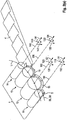
- Fig. 2 (a) shows a perspective view of the drums 11, 12, 13, 14 and baskets 15, 16 of the threshing mechanism 1 according to the invention and the turret shaker 4 downstream of the threshing mechanism 1.
- the threshing mechanism 1 comprises a total of four drums 11, 12, 13, 14.
- the drums 11, 12, 13, 14 each extend concentrically about an axis 110, 120, 130, 140 in an axial direction 111, 121, 131, 141 and are each rotatable in a rotational direction 113, 123, 133, 143 about the axis 110, 120, 130, 140.
- the axes 110, 120, 130, 140 are arranged parallel to each other and spaced from each other.
- the drum 11, 12, 13, 14 with the largest diameter D11, D12, D13, D14 are the threshing drum 12. Their two drums 13, 14, namely a separating drum 13 and a turning drum 14, arranged downstream, which are successively smaller. Besides, you are a smaller feed drum 11 upstream. All four drums 11, 12, 13, 14 are arranged on a in the conveying direction 30 of the crop 3 by the threshing 1 rising concave line 1. This allows, in particular in the conveying direction 30 behind the threshing drum 12, a material flow path without strong Gutumlenkung.
- a concave 15 is arranged, can be deposited by the threshed grain or fruits from the crop 3.
- a concave 15 is arranged below the feed drum 11 and the threshing cylinder 12.
- a concave 15 is arranged below the feed drum 11 and the threshing cylinder 12.
- a concave 15 is arranged below the feed drum 11 and the threshing cylinder 12.
- a concave 15 can be deposited by the threshed grain or fruits from the crop 3.
- a Abscheldekorb 16 is arranged below the Abscheidetrommel 13 . Also through the Abacheidekorb 16 threshed grain or fruits can be deposited.
- the concave 15 wraps around the feed drum 11 and the threshing drum 12 respectively in their circumferential directions 113, 123 at least partially.
- the separation basket 16 wraps around the separation drum 13 in its circumferential direction 133 at least partially.
- the crop 3 is fed to the threshing unit 1 by a gap S arranged between the feed drum 11 and the concave 15.
- Fig. 2 (b) shows the threshing 1 and a section of the Horden—lers 4 of Fig. 2 (a) schematically in a side view. Shown here is also a basket adjustment 9, which includes a Dreschkorbver ein 91 and a Abscheidekorbver ein 92.
- the concave 15 and the separation basket 16 are by means of the basket adjustment 9 in each case approximately in the radial direction 112, 122, 132 (s. Fig. 2 (a) ) to the drum 11, 12, 13, which at least partially wrap around, adjustable.
- a concave position G, V (s. Fig. 4 ) that is, a distance A11, A12, the feed drum 11 and the threshing cylinder 12 to the concave 15, as well as a AbMldekorbposition E, W (s. Fig. 3 . 4 ), that is, a distance A13.1, A13.2 (see also Fig. 3 ) of the separating drum 13 to the separating basket 16, adjustable.
- the threshing unit 1 has the four drums 11, 12, 13, 14 mounted on the concave, ascending line L.
- the feed drum 11 On the input side, the feed drum 11 with respect to its downstream threshing drum 12 smaller diameter D11.
- the concave 16 wraps around at least a portion of the feed drum 11 through the gap S between the feed drum 11 and the concave 15, the crop 3 is supplied to the threshing unit 1 on the input side.
- a sieve (not labeled) in the concave 15 already threshed with the feed drum 11 grain from the rest of crop 3 can be deposited.
- the Zuerftrommel 11 accelerates the crop 3 and leads it to the threshing drum 12.
- the threshing cylinder 12 has the largest diameter D12 of the drums 11, 12, 13, 14 of the threshing unit 1. As a result, a large threshing path (not designated) can be reached.
- the threshing path is determined by a first wrap angle ⁇ 12, around which the concave 15 wraps around the threshing drum 12 in the circumferential direction 123. It is preferably about 100 ° -150 °, particularly preferably about 120 ° -140 °.
- the thus achievable threshing surface is, depending on the diameter D12 of the threshing cylinder 12, between about 1m 2 and 1.7m 2 .
- a threshing element 17 is rotatably arranged in the region of the transition of the feed drum 11 to the threshing drum 12, with which a course of the crop stream 33 can be changed.
- the threshing element 17 can, in particular crop-dependent and / or depending on the harvesting conditions, from a flat position (not designated) In a raised position (not shown) are rotated. In the raised position, the crop 3 is deflected stronger. As a result, it is more threshing there.
- the threshing cylinder 12 is downstream of the separation drum 13.
- the separation drum 13 is provided for conveying and combing out the crop 3.
- a sieve (not designated) in the separation basket 16.
- a second wrap angle ⁇ 13 which determines the separation path (not designated) and around which the separation basket 16 wraps around the separation drum 13, is preferably about 90 ° -125 °, particularly preferably about 100 ° -120 °.
- the separating surface which can be reached in this way is approximately between 0.8 m 2 and 1.2 m 2 .
- the Abscheldrommel 13 is one in the conveying direction 30 with respect to this smaller Subsequent reversing drum 14.
- the turning drum 14 directs the crop 3 to the post-processing device 4. Due to its small diameter D14 it does not disturb the Erntegutstrom 33 unnecessarily.
- the crop stream 33 between the drums 11, 12, 13, 14 and the baskets 15, 16 is schematically indicated by a dashed arrow. It can be seen that it is deflected only slightly in the region of the transition (not designated) from the threshing cylinder 12 to the separating drum 13. Once accelerated crop 3, the threshing 1 can therefore go through without having to be significantly accelerated again. Despite the very large threshing drum diameter D12 and the large Abscheidtrommel 13 required for the threshing unit 1 drive power is therefore sufficiently small.
- the separation basket 13 can be preset both into a narrow separation basket position E and into a wide separation basket position W. This shows the Fig. 3 schematically.
- Fig. 3 shows in (a) and (b) the drums 11, 12, 13, 14 of the threshing unit 1 of Fig. 2 and the Abscheidekorb 16. It shows Fig. 3 (a) the default setting of the separating basket 13 in the narrow Abscheidekorbposition E, in which the distance A13.1 the Abscheidetrommel 13 of the Abscheidekorb 16 is small. Fig. 3 (b) shows the default setting the separation basket 13 in the wide Abscheldekorbposition W, in which the distance A13.2 the Abscheidetrommel 13 of the Abscheidekorb 16 large, in particular greater than in the narrow Abscheidekorbposition E is.
- the separating basket 16 is adjusted by means of the second adjusting lever 932.
- the second adjustment lever 932 is rotated by a rotation angle a, which is shown here only as an example. It is preferable that the second angle lever 932 is rotated by the rotation angle ⁇ of about 180 ° to move the separation basket 16 from the narrow separation basket position E into the wide separation basket position W or back.
- the second adjusting lever 932 can be manually and / or automatically adjustable.
- the concave 15 and the separating basket 16 are adjustable together.
- the first adjusting lever 931 (s. Fig. 2 (B) used.
- the deposited together with the concave 15 Abscheidekorb 16 show the FIGS. 4 ,
- Fig. 4 (a) and (B) show the basket adjustment 9 with narrow preset Abscheidekorbposition E in an adjustment V of the concave 15 in which it is adjusted relative to a basic position G, so that the distance A12 of the threshing cylinder 12 from the concave 15 is greater than in the basic position G is. It is in Fig. 4 (b) an enlarged section Fig. 4 (a) shown.
- Fig. 4 (c) shows the basket adjustment 9 with tight preset Abscheldekorbposition E in the basic position G, in which the concave 15 is fixed, so that the distance A12 of the threshing drum 12 from the concave 15 is minimal.
- Fig. 4 (d) shows the basket adjustment 9 with far pre-set Abscheidekorbposition W in the basic position G of the concealer 15th
- Fig. 4 (e) shows the basket adjustment 9 with far preset Abscheldekorbposition W In the adjustment position V of the concealer 15th
- the Abscheldekorbver ein 92 comprises at least two tabs 901, which are spaced from each other and rotatably attached to the separating basket 13. At the tabs 901 each an angle lever 902 is rotatably mounted.
- the angle lever 902 each have two in a particular right angle (not labeled) to each other arranged legs (not labeled). They are each mounted centrally about a stationary bearing 90 rotatably.
- Each of the tabs 901 opposite ends (not labeled) of the angle lever 902 are connected to each other by means of a connecting strut 903.
- a Versrhiebebautell 933 is provided which is eccentrically adjustable with a second adjusting lever 932, here slidably.
- the connecting component 933 has a receptacle (not designated), which passes through a shaft 952.
- the shaft 952 is eccentric about a rotation axis 95 in a Direction of rotation 951 rotatable.
- the terms shaft 952 and eccentric are used interchangeably.
- a pin 96 is arranged, which is connected by means of a connecting strut 903 with an angle lever 902 of Abscheidekorbver ein 92.
- the pin 96 is guided in a gate 94, which is arranged in a connecting angle lever 904, which is also provided for adjusting the concave 15.
- the connecting member 933 By rotating the eccentric 952 about the axis of rotation 95 in the direction of rotation 951, the connecting member 933 is displaced in a sliding direction 97.
- the connecting strut 903 connected to the angle lever 902 of the separating basket adjustment 92 pulls on the angle lever 902 as described above, so that it rotates about its stationary bearing 90.
- the distance A13.1, A13.2 of the separating basket 16 from the separating drum 13 changes.
- the second adjusting lever 932 is provided for rotating the eccentric 952, with which the eccentric 952 is adjustable into a narrow Abscheldekorbpositionen E and a wide Abscheldekorbposition W.
- the adjusting lever 932 is adjusted by an angle of rotation ⁇ , here by about 180 °, in the direction of rotation 951.
- the distance A13.2 is greater than in the narrow skimmer basket position A13.1.
- the presetting of the deposition basket position E, W is possible independently of the concave position G, V.
- the concave 15 and the separating basket 16 are connected to one another such that when the concave position G, V is adjusted from a basic position G, in which the concave 15 is not adjusted and the distance A12 of the threshing drum 12 from the concave 15 is minimal, an adjustment position V is achieved in which the concave 15 is adjusted and the distance A12 of the threshing cylinder 12 from the concave 15 is greater than in the basic position G, the separating basket 16 is adjusted with.
- the concave adjustment 91 comprises at least two tabs 901, which are spaced apart and rotatably mounted on the concave 15. At the tabs 901 is also a respective angle lever 902, 904 rotatably mounted.
- the angle lever 902, 904 are each rotatably mounted centrally about a stationary bearing 90.
- Each of the tabs 901 opposite ends (not labeled) of the angle lever 902, 904 are connected to each other by means of a connecting strut 903.
- the angle lever 902, 904 When moving the connecting strut 903, the angle lever 902, 904 are each rotated about their stationary bearing 80. In this case, the angle levers 902,904 pull the tabs 901 and with them the concave 15 in about the radial direction 122, 112 of the threshing cylinder 12 or the feed drum 11 passing through axis 120, 110. As a result, the distance A12, A11 of the threshing drum 12 and the changes Feeding drum 11 to the concave 15th
- the concave 15 shown here is formed in two parts in order to ensure a uniform adjustment of the distance A11 of the feed drum 11 from the concave 15 and the distance A12 of the threshing cylinder 12 from the concave 15.
- the Dreschkorbveratellung 91 is so far from the document DE 10 2013 100 057 A1 is known and will therefore not be further described.
Landscapes
- Life Sciences & Earth Sciences (AREA)
- Environmental Sciences (AREA)
- Threshing Machine Elements (AREA)
- Harvester Elements (AREA)
Abstract
Description
- Die vorliegende Erfindung betrifft ein Dreschwerk für einen Mähdrescher, mit zumindest drei zur Bearbeitung des Erntegutes vorgesehenen Trommeln, die eine zum Dreschen der Erntegutes vorgesehene Dreschtrommel umfassen, sowie zumindest zwei der Dreschtrommel in eine Förderrichtung des Erntegutes durch das Dreschwerk nachfolgende Trommeln. Die vorliegende Erfindung betrifft weiterhin einen Mähdrescher mit einem solchen Dreschwerk sowie ein Verfahren zum Einstellen des Dreschwerks.
- Mit Mehrtrommeldreschwerken, insbesondere nach dem Tangentlalflussprinzip, kann auch bei hohem Erntegut-Durchsatz noch ein optimales Druschergebnis erzielt werden. Maßgeblich dafür ist eine sehr gute Abstimmung der Trommeln, der mit den Trommeln zusammenwirkenden Dreschkörbe und der Drehzahlen der Trommeln aufeinander.
- Dafür ist es bekannt, zumindest zwei Dreschtrommeln In Förderrichtung des Erntegutes hintereinander anzuordnen. Die erste Dreschtrommel übernimmt dabei die Aufgabe, auch bei ungleichmäßiger Menge zugeführten Ernteguts den Gutstrom zu vergleichmäßigen, so dass die der zweiten Dreschtrommel zugeführte Erntegutmenge nur in engen Grenzen variiert. Dadurch kann der Ausdrusch verbessert werden.
- Es Ist aber weiterhin erforderlich, dass das Dreschwerk in Abhängigkeit von der Erntegutart, den Erntebedingungen und dem gewünschten Druschergebnis einstellbar ist. Dafür werden ein Abstand der die Dreschtrommeln zumindest teilweise umschlingenden Dreschkörbe und/oder eine Umfangsgeschwindigkeit der Dreschtrommeln verändert. Ein enger Abstand führt zu einem schärferen Druschprozeß, kann aber eine große Menge Körnerbruch bewirken und die Strohqualität verringern. Derngegenüber führt ein weiter Abstand zu verringertem Ausdrusch. Zudem führt eine große Differenz der Dreschtrommeldrehzahlen gegebenenfalls zu erhöhtem Körnerbruch.
- Die Druckschrift
DE 10 2013 100 057 A1 beschäftigt sich mit der Verstellung zweier Dreschkörbe, die zwei in Förderrichtung des Erntegutes hintereinander angeordnete Dreschtrommeln in ihrer Umfangsrichtung teilweise umschlingen. Die Dreschkörbe sind an Winkelhebeln gelagert, die um ortsfeste Achsen schwenkbar sind. Die Winkelhebel sind mittels Verbindungsstangen miteinander und mit einem Hydraulikzylinder verbunden. Durch Verstellen des Hydraulikzylinders werden sie so verschoben, dass die Winkelhebel um ihre Achsen verschwenken. Dadurch werden die Dreschkörbe radial zu den Dreschtrommel verstellt. Die Anordnung ermöglicht eine gleichmäßige Verstellung der Dreschkörbe, durch die der Abstand der Dreschtrommeln zu den Dresohkörben etwa gleichbleibend ist. - Bekannt sind auch Dreschwerke mit einer Dreschtrommel, der das Erntegut unmittelbar vom Schrägförderer zugeführt wird, und einer die Abscheideleistung erhöhenden Abscheidetrommel, die der Dreschtrommel nachgeordnet ist. Um eine große Umschlingung der Dreschtrommel zu erreichen, wird der Dreschkorb in Förderrichtung hinter der Dreschtrommel zumeist sehr hoch geführt und das Erntegut über eine Wendetrommel, die das Erntegut von der Dreschtrommel abnimmt, in die Abscheidetrommel geleitet. Solche Dreschwerke zeigen beispielsweise die Druckschriften
DE 42 18 611 C3 undDE 10 2007 031 807 A1 . - Nachteilig an diesen Dreschwergen ist, dass das Erntegut stark umgelenkt werden muss. Denn dies kann die Strohqualität verschlechtern und zu erhöhtem Körnerbruch führen. Zudem muss das Erntegut bei jeder starken Umlenkung neu beschleunigt werden, was die für den Antrieb des Dreschwerks erforderliche Leistung, sowie den Energieverbrauch des Mähdreschers, erhöht.
- Aufgabe der vorliegenden Erfindung Ist es, ein Dreschwerk für einen insbesondere selbstfahrenden Mähdrescher zu schaffen, das auch bei einer großen Menge gegebenenfalls ungleichmäßig In das Dresohwerk zugeführtem Erntegut eine sehr hohe Abscheideleistung bei geringem Körnerbruch und guter Strohqualität ermöglicht, und das zudem eine möglichst kleine Antriebsleistung benötigt.
- Die Aufgabe wird gelöst mit einem Dreschwerk mit den Merkmalen des unabhängigen Patentanspruchs 1, mit einem Mähdreschermit den Merkmalen das unabhängigen Patentanspruchs 10, sowie mit einem Verfahren mit den Merkmalen des unabhängigen Patentanspruchs 13. Vorteilhafte Ausführungsformen sind den abhängigen Ansprüchen entnehmbar.
- Dafür wird ein Dreschwerk für einen Mähdrescher geschaffen. Das Dreschwerk weist zumindest drei zur Bearbeitung des Erntegutes vorgesehene Trommeln auf, die eine zum Dreschen des Erntegutes vorgesehene Dreschtrommel umfassen. Zudem sind die weiteren beiden Trommeln In eine Förderrichtung des Erntegutes durch das Dreschwerk betrachtet der Dreschtrommel nachgeordnet.
- Das Dreschwerk zeichnet sich dadurch aus, dass
- die Trommeln jeweils einen Durchmesser aufweisen, wobei der Durchmesser der Dreschtrommel am größten Ist,
- die Trommeln auf einer In Förderrichtung etwa konkav verlaufenden, ansteigenden fiktiven Linie gelagert sind, und
- die Durchmesser der auf die Dreschtrommel nachfolgenden Trommeln In Förderrichtung sukzessive kleiner werden.
- Durch die große Dreschtrommel Ist ein ausreichend großer Dreschweg sichergestellt, der eine sehr hohe Abscheidung ermöglicht. Die große Dreschtrommel ermöglicht zudem einen sehr großen Erntagutdurchsatz. Die Lagerung der Trommeln auf der konkav verlaufenden, ansteigenden fiktiven Linie sowie die sukzessive kleiner werdenden Durchmesser der Trommeln ermöglichen trotz der großen Dreschtrommel einen Materialflussverlauf ohne starke Gutumlenkung, insbesondere beim Übergang von der Dreschtrommel zu der Ihr unmittelbar nachgeordneten Trommel. Der Erntegutstrom wird daher nicht immer wieder gestört sondern verläuft insgesamt sehr gleichmäßig, und das Erntegut muss nicht Immer wieder neu beschleunigt werden. Trotz der großen Trommeln, Insbesondere der Dreschtrommel, ist die für den Antrieb des Dreschwerks erforderliche Antriebsleistung daher ausreichend klein.
- Der Durchmesser der Dreschtrommel ist bevorzugt so groß wie möglich. Er ist vor allem durch die Höhe des Mähdreschers begrenzt. Vorzugsweise ist er etwa gleich oder größer als 500mm, besonders bevorzugt Ist er etwa gleich oder größer als 600mm, ganz besonders bevorzugt ist er etwa gleich oder größer als 700mm. Auch bei einer verhältnismäßig kleinen Umschlingung der Dreschtrommel durch den Dreschkorb kann so ein großer Dreschweg sichergestellt werden. Das Dreschwerk ermöglicht daher eine ausreichend hohe Abscheidung.
- Um auch bei der großen Dreschtrommel eine gute Gutannahme des Erntegutes in das Dreschwerk zu gewährleisten, ist der Dreschtrommel bevorzugt eine zum Vordreschen und/oder zur Förderung des Erntegutes vorgesehene Zuführtrommel in Förderrichtung vorgelagert. In dieser Ausführungsform weist das Dreschwerk daher zumindest vier Trommeln auf, Die Zuführtrommel führt auch bei einer großen, Insbesondere ungleichmäßigen, Menge zugeführten Ernteguts zur Vergleichmäßigung des Gutstroms. Außerdem beschleunigt sie das Erntegut, so dass dieses das Dreschwerk mit erhöhter kinetischer Energie durchläuft. Aufgrund der verhältnismäßig geringen Gutumlenkung wirkt sich dies vorteilhaft auf die benötigte Antriebsleistung aus. Zudem ermöglicht die beschleunigte Zufuhr des Erntegutes In die Dreschtrommel, sowie eine gegebenenfalls mit der Zuführtrommel zusammen wirkende zusätzlichen Abscheidefläche, eine noch weiter erhöhte Abscheidung.
- Ein Durchmesser der Zuführtrommel ist bevorzugt kleiner als der der Dreschtrommel. Vorzugsweise weist sie einen Durchmesser auf, der größer als oder etwa gleich 400mm ist, um den gleichmäßigen Erntegutfluss zu gewährleisten. Es Ist weiterhin bevorzugt, dass Ihre Umfangsgeschwindigkeit geringer als die der Dreschtrommel ist, um das Erntegut langsam zu beschleunigen.
- Weiterhin bevorzugt ist die Zuführtrommel auf der fiktiven Linie gelagert. Dadurch kann das Erntegut Im Bereich des Übergangs der Zuführtrommel zur Dreschtrommel gezielt stärker umgelenkt werden. Dies verbessert den Ausdrusch. Besonders bevorzugt Ist In diesem Bereich ein Dreschelement verstellbar, insbesondere verdrehbar, angeordnet, mit dem der Grad der Umlenkung einstellbar ist. Das Dreschelement kann erntegutaphängig und/oder In Abhängigkeit von den Erntebedingungen, beispielsweise feuchtigkeitsabhängig, manuell oder automatisch verstellt werden.
- Die der Dreschtrommel nachgeordneten Trommeln umfassen bevorzugt eine Abscheidetrommel. Die Abscheidetrommel ist zur weiteren Erhöhung der Abscheidung vorgesehen. Vorzugsweise weist die Abscheidetrommei Werkzeuge auf, die den Gutstrom durchkämmen, um ihn zu fördern, aufzulockern und Insbesondere bereits gelöste Körner von diesem zu lösen. Die Abscheldetrommel ist der Dreschtrommel besonders bevorzugt in Förderrichtung unmittelbar nachgeordnet.
- Es ist bevorzugt, dass der Durchmesser der Abscheidetrommel größer als 350mm, besonders bevorzugt größer als 500mm, ist. Aufgrund des Im Vergleich zur Dreschtrommel kleineren Durchmessers der Abscheidetrommel sowie der konkav verlaufenden, in Förderrichtung ansteigenden fiktiven Linie, auf der die Trommeln gelagert sind, ist die Gutumlenkung Im Übergangsbereich zwischen der Dreschtrommel und der Abscheidetrommel gering. Insgesamt kann dennoch eine große Abscheidetrommel, die eine große Abscheidefläche ermöglicht, verwendet werden.
- Weiterhin ist es bevorzugt, dass die der Dreschtrommel nachfolgenden Trommeln eine Wendetrommel umfassen, die der Abscheidetrommel in Förderrichtung, insbesondere unmittelbar, nachgelagert ist. Die Wendetrommel nimmt das Erntegut von der Abscheidetrommel entgegen. Sie ist zum Fördern und/oder Umlenken des Erntegutes vorgesehen. Auch dabei werden noch Körner oder Früchte abgeschieden. Vorzugsweise lenkt die Wendetrommel das Erntegut auf eine Nachbearbeitungseinrichtung für das Erntegut, Insbesondere auf einen Hordenschüttler. Aufgrund der großen Trommeldurchmesser ist es vorteilhaft, die Wendetrommel zum Führen des Erntegutes auf die Nachbearbeitungseinrichtung zu verwenden.
- Der Durchmesser der Wendetrommel Ist bevorzugt größer als 250mm, besonders bevorzugt größer als 300mm. Erfindungsgemäß ist sie zudem kleiner als die Abscheidetrommel, um den Materialfluss nicht unnötig zu stören. Der kleine Durchmesser der Wendetrommel ist zum Führen des Erntegutes ausreichend. Zudem weist die Wendetrommel dadurch ein kleines Gewicht auf, was sich vorteilhaft auf die für das Dreschwerk erforderliche Antriebeleistung auswirkt.
- Dazu starke Differenzen in den Umfangsgeschwindigkeiten Auslöser für Körnerbruch sind, sind die Durchmesser der Trommeln, insbesondere der Dreschtrommel und der beiden ihr nachgeordneten Abscheidetrommel sowie Wendetrommel, so aufeinander abgestimmt, dass der Körnerbruch möglichst gering ist.
- Vorzugsweise ist vor allern die Abscheidetrommel nicht mehr als 40% kleiner als die Dreschtrommel, besonders bevorzugt nicht mehr als 30% kleiner.
- In einer besonders bevorzugten Ausführungsform werden die Drehzahlen aller Trommeln des Dreschwerks synchron, das helßt in einem festen Verhältnis zueinander, eingestellt. Dadurch kann auch bei Verstellung der Drehzahl gewährleistet werden, dass der Körnerbruch gering ist. Zudem ist dies in Bezug auf den gleichmäßigen Erntegutstrom, die Höhe der Abscheidung und die Strohqualität vorteilhaft. Außerdem wird die Drehzahl der Abscheidetrommel so automatisch angepasst. Eine manuelle Umstellung der Drehzahlen der Trommeln auf verschiedene Erntegutarten, beispielsweise von Getreide auf Mais, entfällt.
- Die Bedienung des Dreschwerks ist für den Anwender daher sehr einfach und die Möglichkeit einer Fehibedienung des Dreschwerks ist so gering.
- In einer bevorzugten Ausführungsform, die die Aufgabe ebenfalls löst, umfasst das Dreschwerk einen Dreschkorb und einen Abscheidekorb.
- Der Dreschkorb umgibt bevorzugt zumindest die Dreschtrommel, oder, sofern das Dreschwerk eine Zuführtrommel aufweist, die Zuführtrommel und die Dreschtrommel, In ihren Umfangsrichtungen jeweils zumindest teilweise. Beim Dreschen wirken die Dreschtrommel, oder die Zuführtrommel und die Dreschtrommel, mit dem Dreschkorb zusammen. Um einen möglichst gleichen Abstand der Dreschtrommel, oder der Zuführtrommel und der Dreschtrommel, vom Dreschkorb zu gewährleisten, kann der Dreschkorb auch mehrtellig ausgeführt sein.
- Zudem umfasst das Dreschwerks bevorzugt den Abscheidekorb, der die Abscheidetrommel zumindest teilweise in ihrer Umfangsrichtung umgibt. Beim Abscheiden wirken der Abscheldekorb und die Abscheidetrommel zusammen.
- Der Dreschkorb und der Abscheidekorb sind bevorzugt so miteinander verbunden, dass sie gemeinsam verstellbar sind. Beim Verstellen verändern sich ein Abstand des Dreschkorbes von der Dreschtrommel, oder ein Abstand des Dreschkorbes von der Zuführtrommel und von der Dreschtrommel, sowie ein Abstand des Abscheidekorbes von der Abscheldetrommel, Auch diese Maßnahme vereinfacht die Bedienung des Dreschwerks für den Anwender.
- Dafür ist es bevorzugt, dass das Dreschwerk eine Korbverstellung aufweist, die zum Verstellen des Dreschkorbs und des Abscheidekorbs vorgesehen ist. Zum gemeinsamen Verstellen das Dreschkorbs und des Abscheidekorbs weist die Korbverstellung bevorzugt einen ersten Verstellhebel, insbesondere einen Hydromotor oder einen elektromotorisch angetriebenen Verstellhebel, auf. Zusätzlich oder alternativ kann ein manuell bedienbarer Hebel vorgesehen sein.
- Besonders bevorzugt werden eine Dreschkorbposition des Dreschkorbs, das heißt ein Abstand der Dreschtrommel vom Dreschkorb, und eine Abscheidekorbposition des Abscheidekorbes, das heißt ein Abstand der Abscheldetrommel vom Abscheidekorb, in Abhängigkeit von der Dreschkorbposition ungleich weit verstellt. Dabei ist es weiterhin bevorzugt, dass beim Verstellen des Dreschkorbes und des Abscheidekorbes der Abscheidekorb bei einer engen Dreschkorbposition, d. h. einem geringen Abstand der Dreschtrommel vom Dreschkorb, weniger stark verstellt wird, als bei einer welten Dreschkorbposition, d. h. einem großen Abstand der Dreschtrommel vom Dreschkorb. Die enge Dreschkorbposition ist beispielsweise für Getreide vorteilhaft, die weite Dreschkorbposition für Mais oder Bohnen. Auch die manuelle Umstellung der Dreschkorbposition und/oder der Abscheidekorbposition In Abhängigkeit von der Erntegutart, beispielsweise die Umstellung von Getreide auf Mals, entfällt daher. Die Bedienung des Dreschwerks ist für den Anwender somit noch weiter vereinfacht.
- Um dennoch ein starkes Dreschen bei gleichzeitig guter Strohqualität zu ermöglichen, Ist es in einer weiteren Ausführungsform bevorzugt, dass die Abscheidekorbposition voreinstellbar ist. Dafür ist bevorzugt ein Abstand des Abscheidekorbes von der Abscheidetrommel voreinstellbar. Besonders bevorzugt ist ein enger Abstand oder ein weiter Abstand des Abscheidekorbes von der Abscheidetrommel, unabhängig vom Abstand des Dreschkorbes von der Dreschtrommel, oder des Dreschkorbes von der Zuführtrommel und der Dreschtrommel, voreinstellbar, Es ist ebenfalls bevorzugt, dass der Abstand des Abscheidekorbes von der Abscheidetrommel kontinuierlich veränderbar ist. Durch die Voreinstellung eines weiten Abstandes des Abscheidekorbes von der Abscheidetrommel ist für Erntegut, das ein starkes Dreschen erfordert, beispielsweise für Hartweizen, dennoch eine gute Strohqualität erreichbar.
- Die Korbverstellung ermöglicht daher in Abhängigkeit von dem gewünschten Dreschziel die Wahl zwischen einer besonders großen Abscheidung und einer besonders guten Strohqualität.
- Um das Voreinstellen des Abscheidekorbes, insbesondere vom weiten In den engen Abstand oder vom engen in den weiten Abstand, insbesondere unabhängig vom Verstellen der Dreschkorbposition, zu bewirken, weist das Dreschwerks die Korbverstellung auf, die neben einer Dreschkorbverstellung zum Verstellen des Abstandes des Dreschkorbes von der Dreschtrommel, oder von der Zuführtrommel und der Dreschtrommel, eine Abscheidukorbverstellung aufweist, wobei die Abscheidekorbverstellung zum Verstellen des Abstandes des Abscheidekorbes von der Abscheidetrommel vorgesehen ist. Die Abscheidekorberstellung und die Dreschkorbverstellung sind bevorzugt mit einem Verbindungsbauteil miteinander verbunden, das mittels einer exzentrisch um die Drehachse drehbaren Welle verschiebbar ist. Zum Drehen der Welle weist die Abscheidekorbverstellung bevorzugt einen zweiten Verstellhebel auf. Vorzugsweise ist der Verstellhebel in zwei Positionen verstellbar. Dafür wird die Welle um einen Drehwinkel in eine Drehrichtung gedreht, Insbesondere um etwa 180°. In dieser Ausführungsform ist der Abscheidekorb zumindest In eine enge Abscheidekorbposition, in der sein Abstand von der Abscheidetrommel klein ist, und in eine weite Abscheidekorbposition, in der sein Abstand von der Abscheidetrommel größer als in der engen Abscheidekorbposition ist, verstellbar. Es Ist aber auch eine Ausführungsform bevorzugt, in der der Verstellhebel kontinuierlich verstellbar ist, so dass die Abscheidekorbposition kontinuierlich verstellbar ist.
- Zum Verstellen des Abscheidekorbs, insbesondere zum Drehen der Welle, weist die Abscheidekorbverstellung bevorzugt einen hydromotorischen oder einen elektromotorischen Antrieb auf. Zusätzlich oder alternativ kann eine manuelle Verstellung vorgesehen sein.
- Durch die Anordnung des Verbindungsbauteils wird der Abscheidekorb bei enger Dreschkorbposition beim Verstellen von der engen in die weite Abscheidekorbposition weit geöffnet. Je weiter der Dreschkorb bereits geöffnet ist, umso geringer wirkt sich das exzentrische Verstellen des Verbindungsbauteils auf die endgültige Abscheidekorbposition aus. Die Verstellbarkeit der Abscheidekorbposition ist, Insbesondere bei maximaler Dreschkorbposition, daher begrenzt.
- Die Trommeln des Dreschwerks und seine Ausmaße sind so aufeinander abgestimmt, dass sie eine sehr gute Abscheidung sowie eine sehr gute Strohquailtät bei geringem Kornbruch ermöglichen. Trotzdem ist die für den Antrieb des Dreschwerks erforderliche Antriebsleistung ausreichend klein.
- Die Aufgabe wird weiterhin gelöst mit einem Mähdrescher mit einem solchen Dreschwerk. Der Mähdrescher ist für einen hohen Erntegutdurchsatz ausgelegt. Er weist bevorzugt eine Nachabscheldeeinrichtung, vorzugsweise einen Hordenschüttler, auf, die dem Dreschwerk nachgeordnet ist. Im Hordenschüttler werden Nichtkornbestandteile wie Spreu und Stroh von den Körnern oder Früchten getrennt.
- Zum Einstellen des Dreschwerks ist es bevorzugt, dass der Mähdrescher eine Steuereinheit umfasst, die dazu eingerichtet ist, die Drehzahlen der Trommeln und/oder die Abstände der Trommeln des Dreschwerks von den Körben des Dreschwerks jeweils gemeinsam einzustellen. Vorzugsweise werden die Drehzahlen der Trommeln dabei synchron, das heißt in einem festen Verhältnis zueinander, verstellt. Weiterhin bevorzugt Ist die Steuereinheit zum Voreinstellen der Abscheidekorbposition eingerichtet.
- Dafür ist es besonders bevorzugt, dass der Mähdrescher eine Benutzerschnittstelle aufweist, die ein Einstellen der Drehzahl der Dreschtrommel, der Dreschkorbposition und/oder der Voreinstellung der Abscheidekorbposition ermöglicht. Die Steuereinheit ist dafür vorgesehen, die Drehzahlen der übrigen Trommeln und/oder die Korbpositionen in Abhängigkeit von der Drehzahl der Dreschtrommel, der Dreschkorbposition und/oder der Voreinstellung der Abscheidekorbposition automatisch einzustellen. Vorzugsweise ist ein solches Einstellen der Drehzahl der Dreschtrommel, der Dreschkorbposition und/oder der Voreinstellung der Abscheidekorbposition von der Fahrerkabine aus möglich.
- Weiterhin bevorzugt weist die Benutzerschnittztelle eine Anzeigeeinheit auf, auf der die aktuelle Drehzahl der Dreschtrommel, die aktuelle Dreschkorbposition und/oder die aktuelle Voreinstellung der Abscheidekorbposition dargestellt wird. Besonders bevorzugt werden auf der Anzeigeeinheit zudem die aktuelle Abscheidung, der aktuelle Kornbruch und/oder die aktuelle Strohqualität angezeigt. Aufgrund dieser Rückmeldung kann der Bediener eine optimale Einstellung des Dreschwerks während der Erntefahrt vornehmen.
- Die Aufgabe wird weiterhin gelöst mit einem Verfahren zum Einstellen eines Dreschwerks eines Mähdreschers, bei dem
- zunächst ein Abstand, insbesondere entweder ein enger Abstand oder ein weiter Abstand, des Abscheidekorbes von der Abscheidetrommel voreingestellt wird, und
- bei dem dann, insbesondere in Abhängigkeit von der Erntegutart und/oder den Erntebedingungen, die Abstände des Dreschkorbas von der Dreschtrommel, oder von der Zuführtrommel und der Dreschtrommel, sowie der Abstand des Abscheidekorbes von der Abscheidstrommel, insbesondere in einem festen Verhältnis zueinander synchron, verstellt werden.
- Bevorzugt sieht das Verfahren zudem, insbesondere anschließend, vor, dass die Drehzahlen der Trommeln des Dreschwerks, insbesondere in Abhängigkeit von der Erntegutart und/oder den Erntebedingungen, in einem festen Verhältnis zueinander synchron verstellt werden. Dabei kann das Einstellen der Drehzahlen der Trommeln und/oder der Abstände der Trommeln von den Körben unabhängig voneinander oder in Abhängigkeit voneinander erfolgen.
- Mit dem Verfahren kann das Dreschwerk, insbesondere erntegutabhängig und/oder in Abhängigkeit von den Erntebedingungen, automatisch optimal eingestellt werden. Der Bediener kann dadurch entlastet und Fehlbedienungen können vermieden werden.
- Die Erfindung wird Im Folgenden anhand von Figuren erläutert. Die Figuren sind lediglich beispielhaft und schränken den allgemeinen Erfindungsgedanken nicht ein. Es zeigen:
- Fig. 1
- einen Mähdrescher nach dem Stand der Technik:
- Fig. 2
- in (a) ein erfindungsgemäßes Dreschwerk und eine dem Dreschwerk in einer Förderrichtung nachgeordnete Nachbearbeitungseinrichtung in einer perspektivischen Ansicht, und in (b) schematisch einen Ausschnitt aus (a) in einer Seitenansicht;
- Fig. 3
- in (a) und (b) schematisch eine Voreinstellung einer Abscheidekorbposition; und
- Fig. 4
- in (a) - (e) die Korbverstellung in verschiedenen Positionen.
-
Figur 1 zeigt eine selbstfahrende landwirtschaftliche Erntemaschine 2, hier einen Mähdrescher. Die Begriffe Mähdrescher und selbstfahrende landwirtschaftliche Erntemaschine 2 werden Im Folgenden synonym verwendet Eine Fahrtrichtung des Mähdreschers 2 ist durch einen Pfeil FR gezeigt. - Der Mähdrescher 2 weist eine Frontseite 21 auf, an der eine Fahrerkabine 50 für einen Bediener 55 angeordnet ist. Zudem Ist an der Frontseite 21 ein Schneidwerk 7 angeordnet, welches Erntegut 3 aufnimmt. Das Schneidwerk 7 leitet das Erntegut 3 an einen Schrägförderer 6, über den es als Gutstrom 33 in eine Förderrichtung 30 an ein Dreschwerk 1 geleitet wird. Das hier dargestellte herkömmliche Dreschwerk 1 weist drei Trommeln 11 - 13 auf, nämlich eine Vordreschtrommel 11, die einer Dreschtrommel 12 vorgelagert ist, die Dreschtrommel 12 sowie eine der Dreschtrommel 12 nachgelagerte Umlenktrommel 13. Die Vordreschtrommel ist zum Vordreschen des Erntegutes 3 sowie zum Zuführen des Erntegutes 3 an die Dreschtrommel 12 vorgesehen, die Dreschtrommel 12 drischt das Erntegut 3, und die Umlenktrommel 13 übergibt das Erntegut 3 einer Nachbearbeitungseinrichtung 4, hier einem Hordenschüttler, der zum Reinigen des Erntegutes 3 vorgesehen ist. Die Begriffe Nachbearbeitungseinrichtung 4 und Hordenschüttler werden im Folgenden synonym verwendet.
- Unterhalb des Dreschwerks 1 ist ein Dreschkorb 15 angeordnet, durch den bereits gelöstes Korn aus dem Erntegutstrom 33 abgeschieden wird.
- Die im Dreschwerk 1 und der Nachbearbeitungseinrichtung 4 abgeschiedene Körner werden über einen Rücklaufboden 42 und einen Zuführboden 41 einer mehrere Reinigungssiebe 43 und ein Gebläse 44 umfassenden Reinigungseinrichtung (nicht bezeichnet) zugeführt. Die gereinigten Körner werden anschließend über einen Kornelevator 46 in einen Korntank 8 geleitet. Größere Bestandteile des Gutstromes 33, die nicht durch die Reinigungssiebe 43 fallen können, werden dem Dreschwerk 1 über einen Überkehrelevator 45 erneut zugeführt. Stroh und Spreu (nicht bezeichnet) werden an der Heckseite 22 des Mähdreschers 2 auf dem Boden (nicht bezeichnet) abgelegt oder verteilt.
- In einer Fahrerkabine 50 des Mähdreschers 2 Ist eine Bedienerechnittstelle 51 für einen Bediener 55 des Mähdreschers angeordnet, die zum Einstellen und zum Anzeigen von Parametern des Mähdreschers 2 und/oder des Erntegutes 3 und/oder der Erntebedingungen vorgesehen ist. Die Bedlenerechnittstelle 51 ist mit einer Steuereinheit 5 verbunden, die zum Steuern des Mähdreschers 2 vorgesehen ist. Anzelgbare und/oder einstellbare Parameter des Mähdreschers 2 sind beispielsweise eine Fahrgeschwindigkeit, der Kraftstoffverbrauch, sowie Betriebs- und/oder Einstellungsparameter eines Arbeitsaggregates des Mähdreschers 2, insbesondere des Dreschwerks 1.
-
Fig. 2 (a) zeigt eine perspektivische Ansicht der Trommeln 11, 12, 13, 14 und Körbe 15, 16 des erfindungsgemäßen Dreschwerks 1 sowie den dem Dreschwerk 1 nachgeordneten Hordenschüttler 4. - Das Dreschwerk 1 umfasst insgesamt vier Trommeln 11, 12, 13, 14. Die Trommeln 11, 12, 13, 14 erstrecken sich jeweils konzentrisch um eine Achse 110, 120, 130, 140 in eine axiale Richtung 111, 121, 131, 141 und sind jeweils in eine Drehrichtung 113, 123, 133, 143 um die Achse 110, 120, 130, 140 drehbar. Die Achsen 110, 120, 130, 140 sind parallel zueinander angeordnet und voneinander beabstandet.
- Die Trommel 11, 12, 13,14 mit dem größten Durchmesser D11, D12, D13, D14 (s.
Fig. 2 (b) ) ist die Dreschtrommel 12. lhr sind zwei Trommeln 13, 14, nämlich eine Abscheidetrommel 13 und eine Wendetrommel 14, nachgeordnet, die sukzessive kleiner werden. Zudem ist ihr eine kleinere Zuführtrommel 11 vorgeordnet. Alle vier Trommeln 11, 12, 13, 14 sind auf einer in Förderrichtung 30 des Erntegutes 3 durch das Dreschwerk 1 ansteigenden konkaven Linie 1 angeordnet. Dies ermöglicht, insbesondere in Förderrichtung 30 hinter der Dreschtrommel 12, einen Materialflussverlauf ohne starke Gutumlenkung. - Unterhalb der Zuführtrommel 11 und der Dreschtrommel 12 ist ein Dreschkorb 15 angeordnet, durch den ausgedroschenes Korn oder Früchte vom Erntegut 3 abgeschieden werden können. Unterhalb der Abscheidetrommel 13 ist ein Abscheldekorb 16 angeordnet. Auch durch den Abacheidekorb 16 können ausgedroschenes Korn oder Früchte abgeschieden werden.
- Der Dreschkorb 15 umschlingt die Zuführtrommel 11 und die Dreschtrommel 12 jeweils In Ihren Umfangsrichtungen 113, 123 zumindest teilweise. Der Abscheidekorb 16 umschlingt die Abscheidetrommel 13 in ihrer Umfangsrichtung 133 zumindest teilweise.
- Das Erntegut 3 wird dem Dreschwerk 1 durch einen zwischen der Zuführtrommel 11 und dem Dreschkorb 15 angeordneten Spalt S zugeführt.
-
Fig. 2 (b) zeigt das Dreschwerk 1 sowie einen Ausschnitt des Hordenschüttlers 4 derFig. 2 (a) schematisch in einer Seitenansicht. Dargestellt ist hier zudem eine Korbverstellung 9, die eine Dreschkorbverstellung 91 sowie eine Abscheidekorbverstellung 92 umfasst. - Der Dreschkorb 15 und der Abscheidekorb 16 sind mittels der Korbverstellung 9 jeweils In etwa radialer Richtung 112, 122, 132 (s.
Fig. 2 (a) ) zu der Trommel 11, 12, 13, die sie zumindest teilweise umschlingen, verstellbar. Dadurch ist eine Dreschkorbposition G, V (s.Fig. 4 ), das heißt ein Abstand A11, A12, der Zuführtrommel 11 und der Dreschtrommel 12 zum Dreschkorb 15, sowie eine Abscheldekorbposition E, W (s.Fig. 3 ,4 ), das heißt ein Abstand A13.1, A13.2 (s. auchFig. 3 ) der Abscheidetrommel 13 zum Abscheidekorb 16, verstellbar. - Das Dreschwerk 1 weist die vier auf der konkav verlaufenden, ansteigenden Linie L gelagerte Trommeln 11, 12, 13, 14 auf.
- Eingangsseitig ist die Zuführtrommel 11 mit dem gegenüber der ihr nachgeordneten Dreschtrommel 12 kleineren Durchmesser D11. Der Dreschkorb 16 umschlingt zumindest einen Teil der Zuführtrommel 11. Durch den Spalt S zwischen der Zuführtrommel 11 und dem Dreschkorb 15 wird das Erntegut 3 dem Dreschwerk 1 eingangsseitig zugeführt. Durch ein Sieb (nicht bezeichnet) im Dreschkorb 15 kann bereits mit der Zuführtrommel 11 ausgedroschenes Korn vom übrigen Erntegut 3 abgeschieden werden.
- Die Zufühftrommel 11 beschleunigt das Erntegut 3 und führt es der Dreschtrommel 12 zu. Die Dreschtrommel 12 weist den größten Durchmesser D12 der Trommeln 11, 12, 13, 14 des Dreschwerks 1 auf. Dadurch ist ein großer Dreschweg (nicht bezeichnet) erreichbar. Der Dreschweg ist durch einen ersten Umschlingungswinkel α12 bestimmt, um den der Dreschkorb 15 die Dreschtrommel 12 in Umfangsrichtung 123 umschlingt. Er beträgt bevorzugt etwa 100°-150°, besonders bevorzugt etw a 120°- 140° Die so erreichbare Dreschfläche liegt je nach Durchmesser D12 der Dreschtrommel 12 etwa zwischen 1m2 - 1,7m2.
- Im Bereich der Dreschtrommel 12 werden die meisten Körner und Früchte vom Erntegut 3 gelöst. Durch ein Sieb (nicht bezeichnet) im Dreschkorb 15 werden sie vom Ernteguistrom 33 getrennt.
- Um den Ausdrusch in Abhängigkeit vom Erntegut 3 zu verbessern, ist im Bereich des Übergangs der Zuführtrommel 11 zur Dreschtrommel 12 ein Dreschelement 17 verdrehbar angeordnet, mit dem ein Verlauf des Erntegutstroms 33 veränderbar ist. Das Dreschelement 17 kann, Insbesondere erntegutabhängig und/oder in Abhängigkeit von den Erntebedingungen, aus einer ebenen Stellung (nicht bezeichnet) In eine erhabene Stellung (nicht gezeigt) verdreht werden. In der erhabenen Stellung wird das Erntegut 3 stärker umgelenkt. Dadurch wird es dort stärker ausgedroschen.
- Der Dreschtrommel 12 Ist die Abscheidetrommel 13 nachgeordnet. Die Abscheidetrommel 13 ist zum Fördern und Auskämmen des Erntegutes 3 vorgesehen. Dadurch werden insbesondere bereits gelöste Körner und Früchte aus dem Erntegut 3 gelöst. Sie werden durch ein Sieb (nicht bezeichnet) Im Abscheidekorb 16 vom Erntegut 3 getrennt. Um eine gute Abscheidung im Bereich des Abscheidekorbes 16 zu erreichen, beträgt ein zweiter Umschlingungswinkel α13, der den Abscheideweg (nicht bezeichnet) bestimmt, und um den der Abscheidekorb 16 die Abscheidetrommel 13 umschlingt, bevorzugt etwa 90°- 125°, besonders bevorzugt etwa 100°-120°. Die so erreic hbare Abscheidefläche liegt je nach Durchmesser D13 der Abscheidetrommel 13 etwa zwischen 0,8m2-1,2m2.
- Der Abscheldetrommel 13 ist in Förderrichtung 30 eine gegenüber dieser kleinere Wendetrommel 14 nachgeordnet. Die Wendetrommel 14 lenkt das Erntegut 3 zur Nachbearbeitungseinrichtung 4. Aufgrund Ihres kleinen Durchmessers D14 stört sie den Erntegutstrom 33 nicht unnötig.
- Der Erntsgutstrom 33 zwischen den Trommeln 11, 12, 13, 14 und den Körben 15, 16 ist durch einen gestrichelten Pfeil schematisch angedeutet. Sichtbar ist, dass er vor allem im Bereich des Übergangs (nicht bezeichnet) von der Dreschtrommel 12 zur Abscheidetrommel 13 nur geringfügig umgelenkt wird. Einmal beschleunigtes Erntegut 3 kann das Dreschwerk 1 daher durchlaufen, ohne nochmals erheblich neu beschleunigt werden zu müssen. Trotz des sehr großen Dreschtrommeldurchmessers D12 sowie der großen Abscheidstrommel 13 ist die für das Dreschwerk 1 benötigte Antriebsleistung daher ausreichend klein.
- Um auch bei schnellem Erntegutstrom 33 und starkem Dreschen eine gute Strohqualität gewährleisten zu können, ist der Abscheidekorb 13 sowohl in eine enge Abscheidekorbposition E als auch in eine weite Abscheidekorbposition W voreinstellbar. Dies zeigt die
Fig. 3 schematisch. - Dafür weist die Korbverstellung 9 die Abscheidekorbverstellung 92 auf.
-
Fig. 3 zeigt in (a) und (b) die Trommeln 11, 12, 13, 14 des Dreschwerks 1 derFig. 2 sowie den Abscheidekorb 16. Dabei zeigtFig. 3 (a) die Voreinstellung des Abscheidekorbes 13 in der engen Abscheidekorbposition E, in der der Abstand A13.1 der Abscheidetrommel 13 von dem Abscheidekorb 16 klein ist.Fig. 3 (b) zeigt die Voreinstellung das Abscheidekorbes 13 in der weiten Abscheldekorbposition W, in der der Abstand A13.2 der Abscheidetrommel 13 von dem Abscheidekorb 16 groß, insbesondere größer als in der engen Abscheidekorbposition E, ist. - Der Abscheidekorb 16 wird mittels des zweiten Verstellhebels 932 verstellt. Dafür wird der zweite Verstellhebel 932 um einen Drehwinkel a gedreht, der hier nur beispielhaft gezeigt Ist. Es Ist bevorzugt, dass der zweite Winkelhebel 932 um den Drehwinkel a von etwa 180° verdreht wird, um den Abscheidekorb 16 von der engen Abscheidekorbposition E In die weite Abscheidekorbpositlon W oder zurück zu verstellen. Der zweite Verstellhebel 932 kann manuell und/oder automatisch verstellbar seln.
- Nach dem Voreinstellen des Abscheidekorbes 16 sind der Dreschkorb 15 und der Abscheidekorb 16 gemeinsam verstellbar. Dafür wird der erste Verstellhebel 931 (s.
Fig. 2 (b) genutzt. Den gemeinsam mit dem Dreschkorb 15 verstellten Abscheidekorb 16 zeigen dieFiguren 4 . -
Fig. 4 (a) und(b) zeigen die Korbverstellung 9 mit eng voreingestellter Abscheidekorbposition E in einer Verstellposition V des Dreschkorbs 15, in der dieser gegenüber einer Grundposition G verstellt Ist, so dass der Abstand A12 der Dreschtrommel 12 vom Dreschkorb 15 größer als In der Grundposition G Ist. Dabei Ist inFig. 4 (b) ein vergrößerter Ausschnitt ausFig. 4 (a) dargestellt. -
Fig. 4 (c) zeigt die Korbverstellung 9 mit eng voreingestellter Abscheldekorbposition E in der Grundposition G, in der der Dreschkorb 15 unverstellt ist, so dass der Abstand A12 der Dreschtrommel 12 vom Dreschkorb 15 minimal ist. -
Fig. 4 (d) zeigt die Korbverstellung 9 mit weit voreingestellter Abscheidekorbposition W in der Grundposition G des Dreschkorbs 15. UndFig. 4 (e) zeigt die Korbverstellung 9 mit weit voreingestellter Abscheldekorbposition W In der Verstellposition V des Dreschkorbs 15. - Die Abscheldekorbverstellung 92 umfasst zumindest zwei Laschen 901, die voneinander beabstandet und drehbar am Abscheidekorb 13 befestigt sind. An den Laschen 901 Ist jeweils ein Winkelhebel 902 drehbar befestigt. Die Winkelhebel 902 weisen jeweils zwei in einem insbesondere rechten Winkel (nicht bezeichnet) zueinander angeordnete Schenkel (nicht bezeichnet) auf. Sie sind jeweils mittig um ein ortsfestes Lager 90 drehbar gelagert. Die jeweils der Lasche 901 gegenüber liegenden Enden (nicht bezeichnet) der Winkelhebel 902 sind mittels einer Verbindungsstrebe 903 miteinander verbunden.
- Bei einem Verschieben der Verbindungsstrebe 903 werden die Winkelhebel 902 jeweils um ihr ortsfestes Lager 90 gedreht. Dabei ziehen die Winkelhebel 902 jeweils die Laschen 901 und mit Ihnen den Abscheidekorb 16 in etwa die radiale Richtung 132 der die Abscheldetrommel 13 durchsetzenden Achse 130. Dadurch ändert sich der Abstand A13.1, A13.2 der Abscheidetrommel 13 zum Abscheidekorb 16.
- Zum Verschieben der Verbindungsstrebe 903 Ist ein Versrhiebebautell 933 vorgesehen, das mit einem zweiten Verstellhebel 932 exzentrisch verstellbar, hier verschiebbar, ist.
- Dafür weist das Verbindungsbauteil 933 eine Aufnahme (nicht bezeichnet) auf, die eine Welle 952 durchsetzt. Die Welle 952 ist exzentrisch um eine Drehachse 95 In eine Drehrichtung 951 drehbar. Im Folgenden werden die Begriffe Welle 952 und Exzenter synonym verwendet. Am Verbindungsbauteil 933 ist ein Stift 96 angeordnet, der mittels einer Verbindungsstrebe 903 mit einem Winkelhebel 902 der Abscheidekorbverstellung 92 verbunden Ist. Der Stift 96 Ist in einer Kulisse 94 geführt, die in einem Verbindungswinkelhebel 904 angeordnet Ist, der auch zum Verstellen des Dreschkorbs 15 vorgesehen ist.
- Durch Drehen des Exzenters 952 um die Drehachse 95 in die Drehrichtung 951 wird das Verbindungsbauteil 933 in eine Schieberichtung 97 verschoben. Dabei zieht die mit dem Winkelhebel 902 der Abscheidekorbverstellung 92 verbundene Verbindungsstrebe 903 wie oben beschrieben am Winkelhebel 902, so dass sich dieser um sein ortfestes Lager 90 dreht. Dadurch ändert sich der Abstand A13.1, A13.2 des Abscheidekorbes 16 von der Abscheidetrommel 13.
- In der dargestellten Ausführungsform Ist zum Drehen des Exzenters 952 der zweite Verstellhebel 932 vorgesehen, mit dem der Exzenter 952 In eine enge Abscheldekorbpositionen E und eine weite Abscheldekorbposition W verstellbar ist. Dafür wird der Verstellhebel 932 um einen Drehwinkel α, hier um etwa 180°, In die Drehrichtung 951 verstellt. In der weiten Abscheidekorbposition W ist der Abstand A13.2 größer als in der engen Abscheldekorbposition A13.1.
- Das Voreinstellen der Abscheidekorbposition E, W Ist unabhängig von der Dreschkorbposition G, V möglich. Der Dreschkorb 15 und der Abscheidekorb 16 sind aber so miteinander verbunden, dass bei einem Verstellen der Dreschkorbposition G, V von einer Grundposition G, In der der Dreschkorb 15 unverstellt und der Abstand A12 der Dreschtrommel 12 vom Dreschkorb 15 minimal ist, in eine Verstellposition V, in der der Dreschkorb 15 verstellt und der Abstand A12 der Dreschtrommel 12 vom Dreschkorb 15 größer als in der Grundposition G ist, der Abscheidekorb 16 mit verstellt Wird.
- Zum Verstellen des Dreschkorbes 15 weist die Korbverstellung 9 die Dreschkorbverstellung 91 auf. Auch die Dreschkorbverstellung 91 umfasst zumindest zwei Laschen 901, die voneinander beabstandet und drehbar am Dreschkorb 15 befestigt sind. An den Laschen 901 Ist ebenfalls jeweils ein Winkelhebel 902, 904 drehbar befestigt. Die Winkelhebel 902, 904 sind jeweils mittig um ein ortsfestes Lager 90 drehbar gelagert. Die jeweils der Lasche 901 gegenüber liegenden Enden (nicht bezeichnet) der Winkelhebel 902, 904 sind mittels einer Verbindungsstrebe 903 miteinander verbunden.
- Bei einem Verschieben der Verbindungsstrebe 903 werden die Winkelhebel 902, 904 jeweils um ihr ortsfestes Lager 80 gedreht. Dabei ziehen die Winkelhebel 902,904 Jeweils die Laschen 901 und mit ihnen den Dreschkorb 15 in etwa die radiale Richtung 122, 112 der die Dreschtrommel 12 oder die Zuführtrommel 11 durchsetzenden Achse 120, 110. Dadurch ändert sich der Abstand A12, A11 der Dreschtrommel 12 und der Zuführtrommel 11 zum Dreschkorb 15.
- Der hier dargestellte Dreschkorb 15 ist zweiteilig ausgebildet, um ein gleichmäßiges Verstellen des Abstandes A11 der Zuführtrommel 11 vom Dreschkorb 15 sowie des Abstandes A12 der Dreschtrommel 12 vom Dreschkorb 15 zu gewährleisten. Die Dreschkorbveratellung 91 ist insoweit aus der Druckschrift
DE 10 2013 100 057 A1 bekannt und wird daher nicht noch weiter beschrieben. - Die weite Abscheidekorbposition W ermöglicht auch bei in der Grundposition G befindlichem Dreschkorb 15 noch eine sehr gute Strohqualität.
-
- 1
- Dreschwerk
- 11
- Zuführtrommel
- 12
- Dreschtrommel
- 13
- Abscheldetrommel
- 14
- Wendetrommel
- 15
- Dreschkorb
- 16
- Abscheidekorb
- 17
- Hebel
- 2
- Mähdrescher
- 21
- Frontseite
- 22
- Heckseite
- 3
- Erntegut
- 30
- Förderrichtung
- 33
- Erntegutstrom
- 4
- Nachbearbeitungseinrichtung
- 41
- Zuführboden
- 42
- Rücklaufboden
- 43
- Reinigungssieb
- 44
- Gebläse
- 45
- Überkehrelevator
- 46
- Kornelevator
- 5
- Steuereinheit
- 50
- Fahrerkabine
- 51
- Bedienerschnittstelle
- 55
- Bediener
- 6
- Schrägförderer
- 7
- Vorsatzgerät
- 8
- Korntank
- 9
- Korbverstellung
- 90
- Ortsfestes Lager
- 901
- Lasche
- 902
- Winkelhebel
- 903
- Verbindungsstrebe
- 904
- Verbindungswinkelhebel
- 91
- Dreschkorbverstellung
- 92
- Abscheidekorbverstellung
- 931
- Erster Verstellhebel
- 932
- Zweiter Verstellhebel
- 933
- Verbindungsbauteil
- 94
- Kulisse
- 941
- Verstellweg
- 95
- Drehachse
- 951
- Drehrichtung
- 952
- Exzenter
- 96
- Stift
- 97
- Verschieberichtung
- L
- Fiktive Linie
- D11 - D14
- Durchmesser der Trommeln
- A11, A12, A13.1, A13.2
- Abstand der Trommeln von den Körben
- FR
- Fahrtrichtung
- S
- Spalt zwischen Zuführtrommel und Dreschkorb
- G
- Grundposition des Dreschkorbs
- V
- Verstellposition des Dreschkorbs
- E
- Enge Abscheidekorbposition
- W
- Weite Abscheidekorbposition
- α
- Drehwinkel
- α12
- Umschlingungswinkel Dreschtrommel
- α13
- Umschlingungswinkel Abscheidetrommel
Claims (14)
- Dreschwerk (1) für einen Mähdrescher (2), mit zumindest drei zur Bearbeitung des Erntegutes (3) vorgesehenen Trommeln (12, 13, 14), die eine zum Dreschen der Erntegutes (3) vorgesehene Dreschtrommel (12) umfassen, sowie zumindest zwei der Dreschtrommel (12) in eine Förderrichtung (30) des Erntegutes (3) durch das Dreschwerk (1) nachfolgende Trommeln (13, 14),
dadurch gekennzeichnet, dass• die Trommeln (12, 13, 14) jeweils einen Durchmesser (D12, D13, D14) aufweisen, wobei der Durchmesser (D12) der Dreschtrommel (12) am größten ist,• die Trommeln (12,13,14) auf einer In Förderrichtung (30) etwa konkav verlaufenden, ansteigenden fiktiven Linie (L) gelagert sind, und• die Durchmesser (D13, D14) der auf die Dreschtrommel (12) nachfolgenden Trommeln (13,14) In Förderrichtung (30) sukzessive kleiner werden. - Dreschwerk (1) nach Anspruch 1, dadurch gekennzeichnet, dass der Durchmesser (D12) der Dreschtrommel (12) größer als 500mm Ist, insbesondere größer als 700mm.
- Dreschwerk (1) nach einem der vorhergehenden Ansprüche, dadurch gekennzeichnet, dass der Dreschtrommel (12) zudem eine zum Vordreschen und/oder zur Förderung des Erntegutes (3) vorgesehene Zuführtrommel (11) in Förderrichtung (30) vorgelagert ist, die auf der Linie (L) gelagert ist.
- Dreschwerk (1) nach einem der vorhergehenden Ansprüche, dadurch gekennzeichnet, dass die der Dreschtrommel (12) nachfolgenden Trommeln (13, 14) eine der Dreschtrommel (12) In Förderrichtung (30) nachgelagerte Abscheidetrommel (13) zum Abschelden des Erntegutes (3) umfassen.
- Dreschwerk (1) nach einem der vorhergehenden Ansprüche, dadurch gekennzeichnet, dass die der Dreschtrommel (12) nachfolgenden Trommeln (13, 14) eine der Abscheidetrommel (13) In Förderrichtung (30) nachgelagerte Wendetrommel (14) zum Fördern und/oder Umlenken des Erntegutes (3) umfassen.
- Dreschwerk (1) nach einem der vorhergehenden Ansprüche, dadurch gekennzeichnet, dass eine Drehzahl aller Trommeln (11, 12, 13, 14) des Dreschwerks (1) synchron In einem festen Verhältnis zueinander eingestellt wird.
- Dreschwerk (1), insbesondere nach einem der vorhergehenden Ansprüche, dadurch gekennzeichnet, dass es einen Dreschkorb (15) umfasst, der zumindest die Dreschtrommel (12), oder die Zuführtrommel (11) und die Dreschtrommel (12), in ihren Umfangsrichtungen (113, 123) jeweils zumindest teilweise umschlingt, und dass es einen Abscheidekorb (16) umfasst, der die Abscheidetrommel (13) zumindest teilweise in ihrer Umfangsrichtung (133) umschlingt, wobei der Dreschkorb (15) und der Abscheidekorb (16) so miteinander verbunden sind, dass sie gemeinsam in einem festen Verhältnis zuelnander verstellbar sind, wobei sich ein Abstand (A11, A12) des Dreschkorbes (12) von der Dreschtrommel (15), oder der Zuführtrommel (11) und der Dreschtrommel (12), sowie ein Abstand (A13.1, A13.2) des Abscheidekorbes (16) von der Abscheidetrommel (13) ändert.
- Dreschwerk (1) nach einem der vorhergehenden Ansprüche, dadurch gekennzeichnet, dass ein Abstand (A13.1, A13.2) des Abscheidekorbes (16) von der Abscheidetrommel (13), Insbesondere ein enger Abstand (A13.1) oder ein weiter Abstand (A13.2) des Abscheidekorbes (16) von der Abscheidetrommel (13), unabhängig vom Abstand (A11, A12) des Dreschkorbes (15) von der Dreschtrommel (15), oder der Zuführtrommel (11) und der Dreschtrommel (12), voreinstellbar ist.
- Dreschwerk (1) nach einem der vorhergehenden Ansprüche, dadurch gekennzeichnet, dass das Dreschwerk (1) dafür eine Dreschkorbverstellung (91) zum Verstellen des Abstandes (A11, A12) des Dreschkorbes (15) von der Dreschtrommel (12), oder der Zuführtrommel (11) und der Dreschtrommel (12), umfasst, die mit einer Abscheidekorbverstellung (92) des Dreschwerks (1), die zum Verstellen des Abstandes (A13.1, A13.2) des Abscheidekorbes (16) von der Abscheidetrommel (13) vorgesehen ist, mit einem Verbindungsbauteil (933) verbunden Ist, das mittels einer exzentrisch um eine Drehachse (95) drehbaren Welle (952) verschiebbar ist.
- Mähdrescher (2) mit einem Dreschwerk (1) nach einem der vorherigen Ansprüche.
- Mähdrescher (2) nach Anspruch 10, dadurch gekennzeichnet, dass dem Dreschwerk (1) eine Nachabscheideeinrichtung (4), insbesondere ein Schüttler, nachgeordnet ist.
- Mähdrescher (2) nach einem der Ansprüche 10 -11, dadurch gekennzeichnet, dass er eine Steuereinheit (5) umfasst, die zum Einstellen des Dreschwerks (1) vorgesehen ist, und die dazu eingerichtet ist, die Drehzahlen der Trommeln (11 - 14) und/oder die Abstande (A11, A12, A13.1, A13.2) der Trommeln (11 - 14) von den Körben (15, 16) jeweils In einem festen Verhältnis zueinander synchron zu verstellen.
- Verfahren zum Einstellen eines Dreschwerks (1) eines Mähdreschers (2), Insbesondere nach einem der Ansprüche 1 - 9, bei dem• Ein Abstand (A13.1, A13.2), Insbesondere entweder ein enger Abstand (A13.1) oder ein weiter Abstand (A13.2), des Abscheidekorbes (16) von der Abscheidetrommel (13) voreingestellt wird, und bei dem dann• die Abstände (A11, A12) des Dreschkorbes (15) von der Dreschtrommel (12), oder von der Zuführtrommel (11) und der Dreschtrommel (12), und der Abstand (A13.1, A13.2) des Abscheidekorbes (16) von der Abscheidetrommel (13), Insbesondere in einem festen Verhältnis zueinander synchron, verstellt werden.
- Verfahren nach Anspruch 13, dadurch gekennzeichnet, dass die Drehzahlen der Trommeln (11 - 14) des Dreschwerks (1) In einem festen Verhältnis zueinander synchron verstellt werden.
Applications Claiming Priority (1)
| Application Number | Priority Date | Filing Date | Title |
|---|---|---|---|
| DE102016118333.4A DE102016118333A1 (de) | 2016-09-28 | 2016-09-28 | Dreschwerk für einen Mähdrescher und Mähdrescher mit einem Dreschwerk |
Publications (3)
| Publication Number | Publication Date |
|---|---|
| EP3311651A2 true EP3311651A2 (de) | 2018-04-25 |
| EP3311651A3 EP3311651A3 (de) | 2018-07-25 |
| EP3311651B1 EP3311651B1 (de) | 2021-04-07 |
Family
ID=59257929
Family Applications (1)
| Application Number | Title | Priority Date | Filing Date |
|---|---|---|---|
| EP17001100.1A Active EP3311651B1 (de) | 2016-09-28 | 2017-06-28 | Dreschwerk für einen mähdrescher und mähdrescher mit dem dreschwerk |
Country Status (2)
| Country | Link |
|---|---|
| EP (1) | EP3311651B1 (de) |
| DE (1) | DE102016118333A1 (de) |
Citations (3)
| Publication number | Priority date | Publication date | Assignee | Title |
|---|---|---|---|---|
| DE4218611C2 (de) | 1992-06-05 | 1994-08-04 | Maehdrescherwerke Ag | Separierkorb für einen Mähdrescher |
| DE102007031807A1 (de) | 2007-07-07 | 2009-01-08 | Deere & Company, Moline | Abscheidetrommel für ein Mehrtrommeldreschwerk |
| DE102013100057A1 (de) | 2013-01-04 | 2014-07-10 | Claas Selbstfahrende Erntemaschinen Gmbh | Dreschvorrichtung |
Family Cites Families (4)
| Publication number | Priority date | Publication date | Assignee | Title |
|---|---|---|---|---|
| GB897337A (en) * | 1959-09-05 | 1962-05-23 | Helmut Class | Improvements in or relating to threshing machines |
| DE19631866A1 (de) * | 1996-08-07 | 1998-02-12 | Same Spa | Drescheinrichtung für Mähdrescher |
| DE102006007810A1 (de) * | 2006-02-17 | 2007-09-06 | Claas Selbstfahrende Erntemaschinen Gmbh | Mähdrescher mit mehrstufigem Trennbereich |
| DE102007006926A1 (de) * | 2007-02-05 | 2008-08-14 | Same Deutz- Fahr Deutschland Gmbh | Erntemaschine |
-
2016
- 2016-09-28 DE DE102016118333.4A patent/DE102016118333A1/de not_active Withdrawn
-
2017
- 2017-06-28 EP EP17001100.1A patent/EP3311651B1/de active Active
Patent Citations (3)
| Publication number | Priority date | Publication date | Assignee | Title |
|---|---|---|---|---|
| DE4218611C2 (de) | 1992-06-05 | 1994-08-04 | Maehdrescherwerke Ag | Separierkorb für einen Mähdrescher |
| DE102007031807A1 (de) | 2007-07-07 | 2009-01-08 | Deere & Company, Moline | Abscheidetrommel für ein Mehrtrommeldreschwerk |
| DE102013100057A1 (de) | 2013-01-04 | 2014-07-10 | Claas Selbstfahrende Erntemaschinen Gmbh | Dreschvorrichtung |
Also Published As
| Publication number | Publication date |
|---|---|
| DE102016118333A1 (de) | 2018-03-29 |
| EP3311651B1 (de) | 2021-04-07 |
| EP3311651A3 (de) | 2018-07-25 |
Similar Documents
| Publication | Publication Date | Title |
|---|---|---|
| EP1358789B1 (de) | Mähdrescher mit Strohhäcksler | |
| EP1350424B1 (de) | Mähdrescher mit motorisch verstellbarer Strohleiteinrichtung | |
| EP1733611B1 (de) | Sieb für eine Reinigungseinrichtung eines Mähdreschers | |
| EP3395158B1 (de) | Mähdrescher | |
| EP2796032B1 (de) | Mähdrescher mit einer Reinigungseinrichtung | |
| EP1421843B1 (de) | Mähdrescher mit Strohhäcksler | |
| DE102011085977A1 (de) | Sieb für eine Reinigungseinrichtung eines Mähdreschers | |
| EP0244862A1 (de) | Mähdrescher | |
| EP3203829B1 (de) | Vorrichtung zum bearbeiten von erntegut und verfahren zum steuern eines erntegutflusses in der vorrichtung | |
| EP3420803A1 (de) | Dresch- oder separierkorb für die getreideernte | |
| EP2425702B1 (de) | Mähdrescher | |
| EP3028560B1 (de) | Dreschkorbanordnung für einen mähdrescher | |
| EP3369301B1 (de) | Landwirtschaftliche erntemaschine | |
| EP2036425B1 (de) | Dreschkorbanordnung für einen Mähdrescher | |
| EP0862849B1 (de) | Gutbearbeitungsvorrichtung | |
| DE2503693A1 (de) | Kornabscheidevorrichtung fuer einen maehdrescher | |
| EP2805602B1 (de) | Mähdrescher | |
| DE1241183B (de) | Kombinierte Dresch- und Reinigungsvorrichtung zur Behandlung von Maehgut wie Getreide | |
| DE10359398B3 (de) | Erntegutbergungseinrichtung mit Abstreifelementen | |
| EP3311651A2 (de) | Dreschwerk für einen mähdrescher und mähdrescher mit dem dreschwerk | |
| BE1022970B1 (de) | Verstellanordnung zur Verstellung des Arbeitsspaltes eines Korbes einer Dresch- und/oder Trenneinrichtung | |
| BE1021334B1 (de) | Mähdrescher mit einer zwischen der drescheinrichtung und der reinigung angeordneten nachdrescheinrichtung | |
| EP3210461B1 (de) | Verfahren zum betreiben einer reinigungseinrichtung für einen mähdrescher | |
| WO2014008887A1 (de) | Dreschtrommel sowie eine mit einer solchen dreschtrommel ausgestattete mobile dreschvorrichtung | |
| EP4338574A1 (de) | Mähdrescher mit einer reinigungsvorrichtung |
Legal Events
| Date | Code | Title | Description |
|---|---|---|---|
| PUAI | Public reference made under article 153(3) epc to a published international application that has entered the european phase |
Free format text: ORIGINAL CODE: 0009012 |
|
| STAA | Information on the status of an ep patent application or granted ep patent |
Free format text: STATUS: THE APPLICATION HAS BEEN PUBLISHED |
|
| AK | Designated contracting states |
Kind code of ref document: A2 Designated state(s): AL AT BE BG CH CY CZ DE DK EE ES FI FR GB GR HR HU IE IS IT LI LT LU LV MC MK MT NL NO PL PT RO RS SE SI SK SM TR |
|
| AX | Request for extension of the european patent |
Extension state: BA ME |
|
| PUAL | Search report despatched |
Free format text: ORIGINAL CODE: 0009013 |
|
| AK | Designated contracting states |
Kind code of ref document: A3 Designated state(s): AL AT BE BG CH CY CZ DE DK EE ES FI FR GB GR HR HU IE IS IT LI LT LU LV MC MK MT NL NO PL PT RO RS SE SI SK SM TR |
|
| AX | Request for extension of the european patent |
Extension state: BA ME |
|
| RIC1 | Information provided on ipc code assigned before grant |
Ipc: A01F 12/18 20060101ALI20180620BHEP Ipc: A01F 7/04 20060101AFI20180620BHEP Ipc: A01F 12/28 20060101ALI20180620BHEP |
|
| STAA | Information on the status of an ep patent application or granted ep patent |
Free format text: STATUS: REQUEST FOR EXAMINATION WAS MADE |
|
| 17P | Request for examination filed |
Effective date: 20190125 |
|
| RBV | Designated contracting states (corrected) |
Designated state(s): AL AT BE BG CH CY CZ DE DK EE ES FI FR GB GR HR HU IE IS IT LI LT LU LV MC MK MT NL NO PL PT RO RS SE SI SK SM TR |
|
| GRAP | Despatch of communication of intention to grant a patent |
Free format text: ORIGINAL CODE: EPIDOSNIGR1 |
|
| STAA | Information on the status of an ep patent application or granted ep patent |
Free format text: STATUS: GRANT OF PATENT IS INTENDED |
|
| INTG | Intention to grant announced |
Effective date: 20201111 |
|
| GRAS | Grant fee paid |
Free format text: ORIGINAL CODE: EPIDOSNIGR3 |
|
| GRAA | (expected) grant |
Free format text: ORIGINAL CODE: 0009210 |
|
| STAA | Information on the status of an ep patent application or granted ep patent |
Free format text: STATUS: THE PATENT HAS BEEN GRANTED |
|
| AK | Designated contracting states |
Kind code of ref document: B1 Designated state(s): AL AT BE BG CH CY CZ DE DK EE ES FI FR GB GR HR HU IE IS IT LI LT LU LV MC MK MT NL NO PL PT RO RS SE SI SK SM TR |
|
| REG | Reference to a national code |
Ref country code: GB Ref legal event code: FG4D Free format text: NOT ENGLISH |
|
| REG | Reference to a national code |
Ref country code: AT Ref legal event code: REF Ref document number: 1378477 Country of ref document: AT Kind code of ref document: T Effective date: 20210415 Ref country code: CH Ref legal event code: EP |
|
| REG | Reference to a national code |
Ref country code: DE Ref legal event code: R096 Ref document number: 502017009942 Country of ref document: DE |
|
| REG | Reference to a national code |
Ref country code: IE Ref legal event code: FG4D Free format text: LANGUAGE OF EP DOCUMENT: GERMAN |
|
| REG | Reference to a national code |
Ref country code: LT Ref legal event code: MG9D |
|
| REG | Reference to a national code |
Ref country code: NL Ref legal event code: MP Effective date: 20210407 |
|
| PG25 | Lapsed in a contracting state [announced via postgrant information from national office to epo] |
Ref country code: LT Free format text: LAPSE BECAUSE OF FAILURE TO SUBMIT A TRANSLATION OF THE DESCRIPTION OR TO PAY THE FEE WITHIN THE PRESCRIBED TIME-LIMIT Effective date: 20210407 Ref country code: FI Free format text: LAPSE BECAUSE OF FAILURE TO SUBMIT A TRANSLATION OF THE DESCRIPTION OR TO PAY THE FEE WITHIN THE PRESCRIBED TIME-LIMIT Effective date: 20210407 Ref country code: NL Free format text: LAPSE BECAUSE OF FAILURE TO SUBMIT A TRANSLATION OF THE DESCRIPTION OR TO PAY THE FEE WITHIN THE PRESCRIBED TIME-LIMIT Effective date: 20210407 Ref country code: BG Free format text: LAPSE BECAUSE OF FAILURE TO SUBMIT A TRANSLATION OF THE DESCRIPTION OR TO PAY THE FEE WITHIN THE PRESCRIBED TIME-LIMIT Effective date: 20210707 Ref country code: HR Free format text: LAPSE BECAUSE OF FAILURE TO SUBMIT A TRANSLATION OF THE DESCRIPTION OR TO PAY THE FEE WITHIN THE PRESCRIBED TIME-LIMIT Effective date: 20210407 |
|
| PG25 | Lapsed in a contracting state [announced via postgrant information from national office to epo] |
Ref country code: GR Free format text: LAPSE BECAUSE OF FAILURE TO SUBMIT A TRANSLATION OF THE DESCRIPTION OR TO PAY THE FEE WITHIN THE PRESCRIBED TIME-LIMIT Effective date: 20210708 Ref country code: LV Free format text: LAPSE BECAUSE OF FAILURE TO SUBMIT A TRANSLATION OF THE DESCRIPTION OR TO PAY THE FEE WITHIN THE PRESCRIBED TIME-LIMIT Effective date: 20210407 Ref country code: IS Free format text: LAPSE BECAUSE OF FAILURE TO SUBMIT A TRANSLATION OF THE DESCRIPTION OR TO PAY THE FEE WITHIN THE PRESCRIBED TIME-LIMIT Effective date: 20210807 Ref country code: PT Free format text: LAPSE BECAUSE OF FAILURE TO SUBMIT A TRANSLATION OF THE DESCRIPTION OR TO PAY THE FEE WITHIN THE PRESCRIBED TIME-LIMIT Effective date: 20210809 Ref country code: PL Free format text: LAPSE BECAUSE OF FAILURE TO SUBMIT A TRANSLATION OF THE DESCRIPTION OR TO PAY THE FEE WITHIN THE PRESCRIBED TIME-LIMIT Effective date: 20210407 Ref country code: NO Free format text: LAPSE BECAUSE OF FAILURE TO SUBMIT A TRANSLATION OF THE DESCRIPTION OR TO PAY THE FEE WITHIN THE PRESCRIBED TIME-LIMIT Effective date: 20210707 Ref country code: SE Free format text: LAPSE BECAUSE OF FAILURE TO SUBMIT A TRANSLATION OF THE DESCRIPTION OR TO PAY THE FEE WITHIN THE PRESCRIBED TIME-LIMIT Effective date: 20210407 Ref country code: RS Free format text: LAPSE BECAUSE OF FAILURE TO SUBMIT A TRANSLATION OF THE DESCRIPTION OR TO PAY THE FEE WITHIN THE PRESCRIBED TIME-LIMIT Effective date: 20210407 |
|
| REG | Reference to a national code |
Ref country code: DE Ref legal event code: R097 Ref document number: 502017009942 Country of ref document: DE |
|
| PG25 | Lapsed in a contracting state [announced via postgrant information from national office to epo] |
Ref country code: MC Free format text: LAPSE BECAUSE OF FAILURE TO SUBMIT A TRANSLATION OF THE DESCRIPTION OR TO PAY THE FEE WITHIN THE PRESCRIBED TIME-LIMIT Effective date: 20210407 Ref country code: EE Free format text: LAPSE BECAUSE OF FAILURE TO SUBMIT A TRANSLATION OF THE DESCRIPTION OR TO PAY THE FEE WITHIN THE PRESCRIBED TIME-LIMIT Effective date: 20210407 Ref country code: DK Free format text: LAPSE BECAUSE OF FAILURE TO SUBMIT A TRANSLATION OF THE DESCRIPTION OR TO PAY THE FEE WITHIN THE PRESCRIBED TIME-LIMIT Effective date: 20210407 Ref country code: CZ Free format text: LAPSE BECAUSE OF FAILURE TO SUBMIT A TRANSLATION OF THE DESCRIPTION OR TO PAY THE FEE WITHIN THE PRESCRIBED TIME-LIMIT Effective date: 20210407 Ref country code: RO Free format text: LAPSE BECAUSE OF FAILURE TO SUBMIT A TRANSLATION OF THE DESCRIPTION OR TO PAY THE FEE WITHIN THE PRESCRIBED TIME-LIMIT Effective date: 20210407 Ref country code: ES Free format text: LAPSE BECAUSE OF FAILURE TO SUBMIT A TRANSLATION OF THE DESCRIPTION OR TO PAY THE FEE WITHIN THE PRESCRIBED TIME-LIMIT Effective date: 20210407 Ref country code: SM Free format text: LAPSE BECAUSE OF FAILURE TO SUBMIT A TRANSLATION OF THE DESCRIPTION OR TO PAY THE FEE WITHIN THE PRESCRIBED TIME-LIMIT Effective date: 20210407 Ref country code: SK Free format text: LAPSE BECAUSE OF FAILURE TO SUBMIT A TRANSLATION OF THE DESCRIPTION OR TO PAY THE FEE WITHIN THE PRESCRIBED TIME-LIMIT Effective date: 20210407 |
|
| REG | Reference to a national code |
Ref country code: CH Ref legal event code: PL |
|
| PLBE | No opposition filed within time limit |
Free format text: ORIGINAL CODE: 0009261 |
|
| STAA | Information on the status of an ep patent application or granted ep patent |
Free format text: STATUS: NO OPPOSITION FILED WITHIN TIME LIMIT |
|
| 26N | No opposition filed |
Effective date: 20220110 |
|
| GBPC | Gb: european patent ceased through non-payment of renewal fee |
Effective date: 20210707 |
|
| PG25 | Lapsed in a contracting state [announced via postgrant information from national office to epo] |
Ref country code: LU Free format text: LAPSE BECAUSE OF NON-PAYMENT OF DUE FEES Effective date: 20210628 |
|
| PG25 | Lapsed in a contracting state [announced via postgrant information from national office to epo] |
Ref country code: LI Free format text: LAPSE BECAUSE OF NON-PAYMENT OF DUE FEES Effective date: 20210630 Ref country code: IE Free format text: LAPSE BECAUSE OF NON-PAYMENT OF DUE FEES Effective date: 20210628 Ref country code: GB Free format text: LAPSE BECAUSE OF NON-PAYMENT OF DUE FEES Effective date: 20210707 Ref country code: CH Free format text: LAPSE BECAUSE OF NON-PAYMENT OF DUE FEES Effective date: 20210630 |
|
| PG25 | Lapsed in a contracting state [announced via postgrant information from national office to epo] |
Ref country code: IS Free format text: LAPSE BECAUSE OF FAILURE TO SUBMIT A TRANSLATION OF THE DESCRIPTION OR TO PAY THE FEE WITHIN THE PRESCRIBED TIME-LIMIT Effective date: 20210807 Ref country code: FR Free format text: LAPSE BECAUSE OF NON-PAYMENT OF DUE FEES Effective date: 20210630 Ref country code: AL Free format text: LAPSE BECAUSE OF FAILURE TO SUBMIT A TRANSLATION OF THE DESCRIPTION OR TO PAY THE FEE WITHIN THE PRESCRIBED TIME-LIMIT Effective date: 20210407 |
|
| P01 | Opt-out of the competence of the unified patent court (upc) registered |
Effective date: 20230516 |
|
| PG25 | Lapsed in a contracting state [announced via postgrant information from national office to epo] |
Ref country code: CY Free format text: LAPSE BECAUSE OF FAILURE TO SUBMIT A TRANSLATION OF THE DESCRIPTION OR TO PAY THE FEE WITHIN THE PRESCRIBED TIME-LIMIT Effective date: 20210407 |
|
| PG25 | Lapsed in a contracting state [announced via postgrant information from national office to epo] |
Ref country code: HU Free format text: LAPSE BECAUSE OF FAILURE TO SUBMIT A TRANSLATION OF THE DESCRIPTION OR TO PAY THE FEE WITHIN THE PRESCRIBED TIME-LIMIT; INVALID AB INITIO Effective date: 20170628 |
|
| REG | Reference to a national code |
Ref country code: AT Ref legal event code: MM01 Ref document number: 1378477 Country of ref document: AT Kind code of ref document: T Effective date: 20220628 |
|
| PG25 | Lapsed in a contracting state [announced via postgrant information from national office to epo] |
Ref country code: AT Free format text: LAPSE BECAUSE OF NON-PAYMENT OF DUE FEES Effective date: 20220628 |
|
| PG25 | Lapsed in a contracting state [announced via postgrant information from national office to epo] |
Ref country code: MK Free format text: LAPSE BECAUSE OF FAILURE TO SUBMIT A TRANSLATION OF THE DESCRIPTION OR TO PAY THE FEE WITHIN THE PRESCRIBED TIME-LIMIT Effective date: 20210407 |
|
| PG25 | Lapsed in a contracting state [announced via postgrant information from national office to epo] |
Ref country code: TR Free format text: LAPSE BECAUSE OF FAILURE TO SUBMIT A TRANSLATION OF THE DESCRIPTION OR TO PAY THE FEE WITHIN THE PRESCRIBED TIME-LIMIT Effective date: 20210407 |
|
| PGFP | Annual fee paid to national office [announced via postgrant information from national office to epo] |
Ref country code: DE Payment date: 20240619 Year of fee payment: 8 |
|
| PGFP | Annual fee paid to national office [announced via postgrant information from national office to epo] |
Ref country code: BE Payment date: 20240619 Year of fee payment: 8 |
|
| PG25 | Lapsed in a contracting state [announced via postgrant information from national office to epo] |
Ref country code: MT Free format text: LAPSE BECAUSE OF FAILURE TO SUBMIT A TRANSLATION OF THE DESCRIPTION OR TO PAY THE FEE WITHIN THE PRESCRIBED TIME-LIMIT Effective date: 20210407 |
|
| PGFP | Annual fee paid to national office [announced via postgrant information from national office to epo] |
Ref country code: IT Payment date: 20240625 Year of fee payment: 8 |