EP3310971B1 - Sanitärarmatur für mehrere fluide - Google Patents
Sanitärarmatur für mehrere fluide Download PDFInfo
- Publication number
- EP3310971B1 EP3310971B1 EP16729496.6A EP16729496A EP3310971B1 EP 3310971 B1 EP3310971 B1 EP 3310971B1 EP 16729496 A EP16729496 A EP 16729496A EP 3310971 B1 EP3310971 B1 EP 3310971B1
- Authority
- EP
- European Patent Office
- Prior art keywords
- water
- channel
- fitting
- outlet
- sanitary fitting
- Prior art date
- Legal status (The legal status is an assumption and is not a legal conclusion. Google has not performed a legal analysis and makes no representation as to the accuracy of the status listed.)
- Active
Links
Images
Classifications
-
- E—FIXED CONSTRUCTIONS
- E03—WATER SUPPLY; SEWERAGE
- E03C—DOMESTIC PLUMBING INSTALLATIONS FOR FRESH WATER OR WASTE WATER; SINKS
- E03C1/00—Domestic plumbing installations for fresh water or waste water; Sinks
- E03C1/02—Plumbing installations for fresh water
- E03C1/04—Water-basin installations specially adapted to wash-basins or baths
- E03C1/0404—Constructional or functional features of the spout
-
- E—FIXED CONSTRUCTIONS
- E03—WATER SUPPLY; SEWERAGE
- E03C—DOMESTIC PLUMBING INSTALLATIONS FOR FRESH WATER OR WASTE WATER; SINKS
- E03C1/00—Domestic plumbing installations for fresh water or waste water; Sinks
- E03C1/02—Plumbing installations for fresh water
- E03C1/04—Water-basin installations specially adapted to wash-basins or baths
- E03C1/0411—Taps specially designed for dispensing boiling water
-
- E—FIXED CONSTRUCTIONS
- E03—WATER SUPPLY; SEWERAGE
- E03C—DOMESTIC PLUMBING INSTALLATIONS FOR FRESH WATER OR WASTE WATER; SINKS
- E03C2201/00—Details, devices or methods not otherwise provided for
- E03C2201/40—Arrangement of water treatment devices in domestic plumbing installations
- E03C2201/45—Arrangement of water treatment devices in domestic plumbing installations for carbonated water
Definitions
- the present invention relates to a sanitary fitting for mixing cold water and hot water to form mixed water with a desired mixed water temperature according to the preamble of claim 1.
- Such sanitary fittings are regularly used in connection with wash basins, sinks, showers and/or bathtubs.
- Sanitary fittings with a water guide arranged in a fitting housing are known from the prior art, the water guide at least partially guiding the mixed water in the sanitary fitting, i.e. specifying the flow path of the mixed water.
- sanitary fittings are known from the prior art with which, in addition to the mixed water, other fluids, such as carbonated water, hot water and/or water with flavors, can be tapped. These fluids are routed separately from the mixed water in the sanitary fittings. In order to ensure the separation of the mixed water from the other fluids in the sanitary fittings, a large number of components are required for guiding the mixed water and the other fluids, which increase the assembly effort of the sanitary fittings.
- WO 2011/076293 A1 a water fitting with at least two lower inlet channels and an upper outlet is known, in which each inlet channel is connected to the outlet via a controllable shut-off device.
- US 2003/102256 A1 is a combination tap with an external water purifier that is able to prevent the formation of unwanted bacteria.
- Another water fitting with an additional fluid guide is from the WO2008/125865 became known, which is complicated in structure.
- the object of the invention is therefore to at least partially solve the problems described with reference to the prior art and to provide a sanitary fitting for two separately guided fluids, which is characterized by a small number of components.
- a sanitary fitting according to the features of the independent patent claim contributes to solving this problem. Further advantageous configurations of the sanitary fitting are specified in the dependently formulated patent claims.
- the sanitary fitting for mixing cold water and hot water to form mixed water with a desired mixed water temperature has a water guide arranged at least partially in a fitting housing and an outlet, the water guide having a first channel for the mixed water and a second channel for a secondary fluid and wherein the second channel is at least partially designed as a connection nipple made in one piece with the water guide.
- the sanitary fitting here is used to mix cold water with a cold water temperature and hot water with a hot water temperature to form mixed water with a desired mixed water temperature and to tap or dispense the mixed water and at least one further secondary fluid.
- the cold water can have a cold water temperature of 0 - 40 °C (Celsius) and/or the hot water can have a hot water temperature of 40 - 90 °C.
- the secondary fluid can in particular be carbonated water, hot water, for example with a hot water temperature of 90 - 100 ° C, or water with a flavoring.
- Such sanitary fittings are regularly used in connection with wash basins, sinks, showers and/or bathtubs.
- the sanitary fitting has a fitting housing, which can consist at least partially of die-casting, in particular zinc die-casting or brass die-casting. Furthermore, the sanitary fitting has an outlet, which is in particular at least partially tubular and is attached to the fitting housing, in particular in a pivotable manner. The outlet leads from the fitting housing to an outlet opening of the sanitary fitting, from which the mixed water and the secondary fluid can emerge from the sanitary fitting when tapped.
- the sanitary fitting can in turn be attached to a support, such as, via the fitting housing for example, a table top, a wall, a washbasin, a sink or a bathtub.
- a water guide is at least partially arranged in the fitting housing and/or in the outlet.
- the water guide can at least partially consist of plastic and can be produced, for example, by a plastic injection molding process.
- the water supply can also be at least partially made of metal, in particular brass.
- the water guide can in particular be inserted at least partially into the fitting housing, for example through an opening in the fitting housing, and/or projects at least partially into the outlet of the sanitary fitting.
- the water guide can also serve in the manner of a guide nipple for the spout, onto which the spout can be attached.
- the water guide also serves in particular as a guide for the mixed water and the secondary fluid.
- the water supply has a first channel for the mixed water and a second channel for the secondary fluid.
- the second channel is at least partially designed as a connection nipple, which is made in one piece with the water supply.
- connection nipple is not a separate component, but is made in one piece with the water supply.
- the connection nipple is also at least partially tubular and serves to connect a hose by means of which the secondary fluid can be directed through the outlet to an outlet opening of the outlet.
- the water supply therefore has an integrated connection nipple, which advantageously reduces the number of components of the sanitary fitting.
- the first channel opens into a first hose or the second channel into a second hose, wherein the mixed water can be conducted by means of the first hose or the secondary fluid by means of the second hose through an outlet of the sanitary fitting to an outlet opening.
- the first hose and/or second hose are in particular (flexible) plastic hoses through which the mixed water and/or the secondary fluid can be conducted to the outlet opening of the outlet without the mixed water and/or the secondary fluid comes into contact with the fitting housing and/or the outlet. This allows the fitting housing and/or the spout to be made from a material that would normally not be suitable for drinking water or food.
- a second hose can be attached to the connection nipple.
- the second hose can either be plugged onto the connection nipple or screwed on.
- connection nipple protrudes from the water supply at an end of the water supply facing the outlet of the sanitary fitting.
- first channel and the second channel are at least partially coaxial. This means in particular that the first channel at least partially surrounds the second channel and/or the second channel runs at least partially through the first channel.
- the sanitary fitting has a cartridge receptacle for holding a mixing cartridge, wherein the mixed water can be fed from the mixing cartridge via the cartridge receptacle to the first channel of the water supply.
- the cartridge holder can in particular be a plastic or metal component into which the mixing cartridge can be inserted and/or the mixing cartridge can be fixed in the fitting housing.
- the mixing cartridge can in particular be a mixing valve or a thermostatic cartridge.
- the supply line can in particular be a (flexible) plastic or metal line.
- the secondary fluid can be supplied to the water supply orthogonally to a longitudinal direction of the water supply.
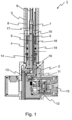
- the Fig. 1 shows schematically and in partial cross-section a sanitary fitting 1 for mixing cold water and hot water to form mixed water with a desired mixed water temperature.
- the sanitary fitting 1 has a fitting housing 2, to which an outlet 3 is pivotally attached.
- the outlet 3 leads to an outlet opening of the sanitary fitting 1, not shown here.
- a water guide 4 and a cartridge holder 11 are arranged in the fitting housing 2 and the outlet 3.
- a mixing cartridge 12 can be fixed in the fitting housing 2.
- an actuator 15 for example a lever
- a user of the sanitary fitting 1 can set a mixed water temperature and/or a withdrawal quantity of the mixed water from the outlet opening of the sanitary fitting 1, not shown here.
- the mixed water mixed by the mixing cartridge 12 can be fed to a first channel 5 of the water supply 4 by means of the cartridge receptacle 11 via a first flow path 16 of the mixed water.
- the first channel 5 for the mixed water opens into a first hose 8, by means of which the mixed water can be directed to the outlet opening.
- a secondary fluid can be supplied to a second channel 6 of the water supply 4 by means of a supply line 13, so that the secondary fluid forms a second flow path 17 in the sanitary fitting 1.
- the supply line 13 opens into the water guide 4 orthogonally to a longitudinal direction 14 of the water guide 4.
- the second channel 6 is designed as a connecting nipple 7 at its end 10 projecting into the outlet 3 and is designed in one piece or in two parts with the water guide 4.
- the connecting nipple 7 also protrudes from the water guide 4 at the end 10 of the water guide 4 facing the outlet 3 of the sanitary fitting 1.
- a second hose 9 can be attached to the connection nipple 7, so that the secondary fluid can be fed to the outlet opening via the second hose 9.
- the outlet 3 is also attached to the water guide 4, so that the water guide 4 serves as a guide nipple 18 of the outlet 3.
- a sleeve 19 is arranged in the outlet 3, with which the outlet 3 sits on the guide nipple 18 of the water guide 4.
- the sanitary fitting proposed here is particularly characterized by a small number of components.
Landscapes
- Health & Medical Sciences (AREA)
- Life Sciences & Earth Sciences (AREA)
- Engineering & Computer Science (AREA)
- Hydrology & Water Resources (AREA)
- Public Health (AREA)
- Water Supply & Treatment (AREA)
- Domestic Plumbing Installations (AREA)
Description
- Die vorliegende Erfindung betrifft eine Sanitärarmatur zum Mischen eines Kaltwassers und eines Warmwassers zu einem Mischwasser mit einer gewünschten Mischwassertemperatur gemäß dem Oberbegriff von Anspruch 1. Solche Sanitärarmaturen werden regelmäßig im Zusammenhang mit Waschbecken, Spülbecken, Duschen und/oder Badewannen verwendet.
- Aus dem Stand der Technik sind Sanitärarmaturen mit einer in einem Armaturengehäuse angeordneten Wasserführung bekannt, wobei die Wasserführung das Mischwasser in der Sanitärarmatur zumindest teilweise führt, also den Strömungspfad des Mischwassers vorgibt. Weiterhin sind aus dem Stand der Technik Sanitärarmaturen bekannt, mit denen neben dem Mischwasser weitere Fluide, wie zum Beispiel karbonisiertes Wasser, Heißwasser und/oder Wasser mit Geschmacksstoffen, zapfbar sind. Diese Fluide werden in den Sanitärarmaturen getrennt von dem Mischwasser geführt. Um die Trennung des Mischwassers von den weiteren Fluiden in den Sanitärarmaturen zu gewährleisten, sind eine Vielzahl von Bauteilen zur Führung des Mischwassers und der weiteren Fluide erforderlich, die den Montageaufwand der Sanitärarmaturen erhöhen.
- Aus der
WO 2011/076293 A1 ist eine Wasserarmatur mit mindestens zwei unteren Zulaufkanälen und einem oberen Auslauf bekannt, bei welcher jeder Zulaufkanal über jeweils ein steuerbares Absperrorgan mit dem Auslauf verbunden ist. Aus derUS 2003/102256 A1 ist ein Kombinationshahn mit externem Wasserreiniger bekannt, der in der Lage ist, die Bildung unerwünschter Bakterien zu verhindern. Eine weitere Wasserarmatur mit einer zusätzlichen Fluidführung ist aus derWO2008/125865 bekannt geworden, die kompliziert im Aufbau ist. - Aufgabe der Erfindung ist daher, die mit Bezug auf den Stand der Technik geschilderten Probleme zumindest teilweise zu lösen und eine Sanitärarmatur für zwei getrennt voneinander geführte Fluide anzugeben, die sich durch eine geringe Bauteilanzahl auszeichnet.
- Zur Lösung dieser Aufgabe trägt eine Sanitärarmatur gemäß den Merkmalen des unabhängigen Patentanspruchs bei. Weitere vorteilhafte Ausgestaltungen der Sanitärarmatur sind in den abhängig formulierten Patentansprüchen angegeben.
- Darüber hinaus werden die in den Patentansprüchen angegebenen Merkmale in der Beschreibung näher präzisiert und erläutert, wobei weitere bevorzugte Ausgestaltungen der Erfindung dargestellt werden.
- Die Sanitärarmatur zum Mischen eines Kaltwassers und eines Warmwassers zu einem Mischwasser mit einer gewünschten Mischwassertemperatur weist eine zumindest teilweise in einem Armaturengehäuse und einem Auslauf angeordnete Wasserführung auf, wobei die Wasserführung einen ersten Kanal für das Mischwasser und einen zweiten Kanal für ein Sekundärfluid aufweist und wobei der zweite Kanal zumindest teilweise als mit der Wasserführung einteilig ausgeführter Anschlussnippel ausgebildet ist.
- Die hier Sanitärarmatur dient dem Mischen eines Kaltwassers mit einer Kaltwassertemperatur und eines Warmwassers mit einer Warmwassertemperatur zu einem Mischwasser mit einer gewünschten Mischwassertemperatur sowie dem Zapfen bzw. der Abgabe des Mischwassers und zumindest eines weiteren Sekundärfluids. Das Kaltwasser kann dabei eine Kaltwassertemperatur von 0 - 40 °C (Celsius) und/oder das Warmwasser eine Warmwassertemperatur von 40 - 90 °C aufweisen. Bei dem Sekundärfluid kann es sich insbesondere um karbonisiertes Wasser, Heißwasser, beispielsweise mit einer Heißwassertemperatur von 90 - 100 °C, oder Wasser mit einem Geschmacksstoff handeln. Solche Sanitärarmaturen werden regelmäßig im Zusammenhang mit Waschbecken, Spülbecken, Duschen und/oder Badewannen verwendet.
- Die Sanitärarmatur weist ein Armaturengehäuse auf, das zumindest teilweise aus Druckguss, insbesondere Zinkdruckguss oder Messingdruckguss, bestehen kann. Weiterhin weist die Sanitärarmatur einen Auslauf auf, der insbesondere zumindest teilweise rohrförmig ausgebildet und an dem Armaturengehäuse, insbesondere verschwenkbar, befestigt ist. Der Auslauf führt von dem Armaturengehäuse zu einer Austrittsöffnung der Sanitärarmatur, aus der das Mischwasser und das Sekundärfluid aus der Sanitärarmatur beim Zapfen austreten können. Über das Armaturengehäuse kann die Sanitärarmatur wiederum an einem Träger, wie zum Beispiel einer Tischplatte, einer Wand, einem Waschbecken, einem Spülbecken oder einer Badewanne, befestigt sein.
- In dem Armaturengehäuse und/oder in dem Auslauf ist zumindest teilweise eine Wasserführung angeordnet. Die Wasserführung kann zumindest teilweise aus Kunststoff bestehen und beispielsweise durch ein Kunststoffspritzgussverfahren hergestellt sein. Weiterhin kann die Wasserführung auch zumindest teilweise aus Metall, insbesondere Messing, bestehen. Die Wasserführung ist insbesondere zumindest teilweise, beispielweise durch eine Öffnung in dem Armaturengehäuse, in das Armaturengehäuse einsetzbar und/oder ragt zumindest teilweise in den Auslauf der Sanitärarmatur. Dabei kann die Wasserführung auch nach Art eines Führungsnippels für den Auslauf dienen, auf den der Auslauf aufsteckbar ist. Die Wasserführung dient zudem insbesondere als Führung für das Mischwasser und das Sekundärfluid. Hierzu weist die Wasserführung einen ersten Kanal für das Mischwasser und einen zweiten Kanal für das Sekundärfluid auf. Der zweite Kanal ist zumindest teilweise als Anschlussnippel ausgebildet, der mit der Wasserführung einteilig ausgeführt ist. Dies bedeutet mit anderen Worten, dass der Anschlussnippel kein separates Bauteil darstellt, sondern einstückig mit der Wasserführung gefertigt ist. Der Anschlussnippel ist zudem zumindest teilweise rohrförmig ausgebildet und dient dem Anschluss eines Schlauchs, mittels dem das Sekundärfluid durch den Auslauf zu einer Austrittsöffnung des Auslaufs leitbar ist. Die Wasserführung weist somit einen integrierten Anschlussnippel auf, wodurch die Bauteilanzahl der Sanitärarmatur in vorteilhafter Weise reduziert wird.
- Zudem münden der erste Kanal in einen ersten Schlauch oder der zweite Kanal in einen zweiten Schlauch, wobei das Mischwasser mittels des ersten Schlauchs oder das Sekundärfluid mittels des zweiten Schlauchs durch einen Auslauf der Sanitärarmatur zu einer Austrittsöffnung leitbar sind. Bei dem ersten Schlauch und/oder zweiten Schlauch handelt es sich insbesondere um (flexible) Kunststoffschläuche, durch die das Mischwasser und/oder das Sekundärfluid zu der Austrittsöffnung des Auslaufs leitbar sind, ohne dass das Mischwasser und/oder das Sekundärfluid mit dem Armaturengehäuse und/oder dem Auslauf in Berührung kommen. Hierdurch kann das Armaturengehäuse und/oder der Auslauf aus einem Material gefertigt werden, das für Trinkwasser bzw. Lebensmittel normalerweise nicht geeignet wäre. Des Weiteren ist es vorteilhaft, wenn ein zweiter Schlauch an dem Anschlussnippel befestigbar ist. Hierzu kann der zweite Schlauch entweder auf den Anschlussnippel aufsteckbar oder aufschraubbar sein.
- Weiterhin ist es vorteilhaft, wenn der Anschlussnippel an einem Auslauf der Sanitärarmatur zugewandten Ende der Wasserführung aus der Wasserführung hinausragt.
- Zudem ist es vorteilhaft, wenn der erste Kanal und der zweite Kanal zumindest teilweise koaxial ausgebildet sind. Die bedeutet insbesondere, dass der erste Kanal den zweiten Kanal zumindest teilweise umgibt und/oder der zweite Kanal zumindest teilweise durch den ersten Kanal verläuft.
- Die Sanitärarmatur weist eine Kartuschenaufnahme zur Aufnahme einer Mischkartusche auf, wobei das Mischwasser von der Mischkartusche über die Kartuschenaufnahme dem ersten Kanal der Wasserführung zuführbar ist. Bei der Kartuschenaufnahme kann es sich insbesondere um ein Kunststoff- oder Metallbauteil handeln, in das die Mischkartusche einsteckbar ist und/oder die Mischkartusche in dem Armaturengehäuse fixierbar ist. Bei der Mischkartusche kann es sich insbesondere um ein Mischventil oder eine Thermostatkartusche handeln.
- Weiterhin ist es vorteilhaft, wenn in die Wasserführung eine Zuführleitung für das Sekundärfluid einsteckbar ist. Bei der Zuführleitung kann es sich insbesondere um eine (flexible) Kunststoff- oder Metallleitung handeln.
- Das Sekundärfluid ist der Wasserführung orthogonal zu einer Längsrichtung der Wasserführung zuführbar.
- Die Erfindung sowie das technische Umfeld werden nachfolgend anhand der Figur näher erläutert. Es ist darauf hinzuweisen, dass die Figur eine besonders bevorzugte Ausführungsvariante der Erfindung zeigt, diese jedoch nicht darauf beschränkt ist.
- Die
Fig. 1 zeigt schematisch und im Teilquerschnitt eine Sanitärarmatur 1 zum Mischen eines Kaltwassers und eines Warmwassers zu einem Mischwasser mit einer gewünschten Mischwassertemperatur. Die Sanitärarmatur 1 weist ein Armaturengehäuse 2 auf, an dem ein Auslauf 3 schwenkbar befestigt ist. Der Auslauf 3 führt zu einer hier nicht gezeigten Austrittsöffnung der Sanitärarmatur 1. In dem Armaturengehäuse 2 und dem Auslauf 3 sind eine Wasserführung 4 und eine Kartuschenaufnahme 11 angeordnet. Mit der Kartuschenaufnahme 11 ist eine Mischkartusche 12 in dem Armaturengehäuse 2 fixierbar. Mittels eines Aktuators 15, beispielsweise einem Hebel, kann durch einen Benutzer der Sanitärarmatur 1 eine Mischwassertemperatur und/oder eine Entnahmemenge des Mischwassers aus der hier nicht gezeigten Austrittsöffnung der Sanitärarmatur 1 eingestellt werden. Das durch die Mischkartusche 12 gemischte Mischwasser ist mittels der Kartuschenaufnahme 11 über einen ersten Strömungspfad 16 des Mischwassers einem ersten Kanal 5 der Wasserführung 4 zuführbar. Der erste Kanal 5 für das Mischwasser mündet in einen ersten Schlauch 8, mittels dem das Mischwasser zu der Austrittsöffnung leitbar ist. Weiterhin ist einem zweiten Kanal 6 der Wasserführung 4 mittels einer Zuführleitung 13 ein Sekundärfluid zuführbar, sodass das Sekundärfluid in der Sanitärarmatur 1 einen zweiten Strömungspfad 17 ausbildet. Die Zuführleitung 13 mündet in die Wasserführung 4 orthogonal zu einer Längsrichtung 14 der Wasserführung 4. Der zweite Kanal 6 ist an seinem in den Auslauf 3 ragenden Ende 10 als Anschlussnippel 7 ausgeführt und einteilig oder zweiteilig mit der Wasserführung 4 ausgebildet. Der Anschlussnippel 7 ragt an dem Auslauf 3 der Sanitärarmatur 1 zugewandten Ende 10 der Wasserführung 4 zudem aus der Wasserführung 4 heraus. Dadurch ist an dem Anschlussnippel 7 ein zweiter Schlauch 9 befestigbar, sodass das Sekundärfluid über den zweiten Schlauch 9 der Austrittsöffnung zuführbar ist. Der Auslauf 3 ist zudem auf die Wasserführung 4 aufgesteckt, sodass die Wasserführung 4 als Führungsnippel 18 des Auslaufs 3 dient. Hierzu ist in dem Auslauf 3 eine Hülse 19 angeordnet, mit der der Auslauf 3 auf dem Führungsnippel 18 der Wasserführung 4 sitzt. - Die hier vorgeschlagene Sanitärarmatur zeichnet sich insbesondere durch eine geringe Bauteilanzahl aus.
-
- 1
- Sanitärarmatur
- 2
- Armaturengehäuse
- 3
- Auslauf
- 4
- Wasserführung
- 5
- erster Kanal
- 6
- zweiter Kanal
- 7
- Anschlussnippel
- 8
- erster Schlauch
- 9
- zweiter Schlauch
- 10
- Ende
- 11
- Kartuschenaufnahme
- 12
- Mischkartusche
- 13
- Zuführleitung
- 14
- Längsrichtung
- 15
- Aktuator
- 16
- erster Strömungspfad
- 17
- zweiter Strömungspfad
- 18
- Führungsnippel
- 19
- Hülse
Claims (6)
- Sanitärarmatur (1) zum Mischen eines Kaltwassers und eines Warmwassers zu einem Mischwasser mit einer gewünschten Mischwassertemperatur, aufweisend ein Armaturengehäuse (2), einen Auslauf (3) und eine zumindest teilweise in dem Armaturengehäuse (2) oder dem Auslauf (3) als separates Bauteil angeordnete Wasserführung (4), wobei die Wasserführung (4) einen ersten Kanal (5) für das Mischwasser und einen zweiten Kanal (6) für ein Sekundärfluid aufweist, wobei der zweite Kanal (6) zumindest teilweise als mit der Wasserführung (4) einteilig ausgeführter Anschlussnippel (7) ausgebildet ist, wobei der zweite Kanal (6) in einen Schlauch (9) der Sanitärarmatur mündet, und das Sekundärfluid mittels des zweiten Schlauchs (9) durch den Auslauf (3) zu einer Austrittsöffnung der Sanitärarmatur leitbar ist, wobei der Schlauch (9) an dem Anschlussnippel (7) befestigt ist, dadurch gekennzeichnet, dass die Sanitärarmatur (1) eine Kartuschenaufnahme (11) zur Aufnahme einer Mischkartusche (12) aufweist, wobei das Mischwasser von der Mischkartusche (12) über die Kartuschenaufnahme (11) dem ersten Kanal (5) der Wasserführung (4) zuführbar ist.
- Sanitärarmatur (1) nach Patentanspruch 1, wobei der Anschlussnippel (7) an einem dem Auslauf (3) zugewandten Ende (10) der Wasserführung (4) aus der Wasserführung (4) hinausragt.
- Sanitärarmatur (1) nach einem der vorhergehenden Patentansprüche, wobei der erste Kanal (5) und der zweite Kanal (6) zumindest teilweise koaxial ausgebildet sind.
- Sanitärarmatur (1) nach einem der vorhergehenden Patentansprüche, wobei in die Wasserführung (4) eine Zuführleitung (13) für das Sekundärfluid einsteckbar ist.
- Sanitärarmatur (1) nach einem der vorhergehenden Patentansprüche, wobei das Sekundärfluid der Wasserführung (4) orthogonal zu einer Längsrichtung (14) der Wasserführung (4) zuführbar ist.
- Sanitärarmatur (1) nach einem der vorhergehenden Patentansprüche, wobei die Wasserführung (4) zumindest teilweise durch eine Öffnung in dem Armaturengehäuse (2) in das Armaturengehäuse (2) einsetzbar ist und zumindest teilweise in den Auslauf (3) ragt.
Applications Claiming Priority (2)
| Application Number | Priority Date | Filing Date | Title |
|---|---|---|---|
| DE102015007897.6A DE102015007897A1 (de) | 2015-06-22 | 2015-06-22 | Sanitärarmatur für mehrere Fluide |
| PCT/EP2016/001017 WO2016206786A1 (de) | 2015-06-22 | 2016-06-16 | Sanitärarmatur für mehrere fluide |
Publications (2)
| Publication Number | Publication Date |
|---|---|
| EP3310971A1 EP3310971A1 (de) | 2018-04-25 |
| EP3310971B1 true EP3310971B1 (de) | 2024-01-17 |
Family
ID=56132885
Family Applications (1)
| Application Number | Title | Priority Date | Filing Date |
|---|---|---|---|
| EP16729496.6A Active EP3310971B1 (de) | 2015-06-22 | 2016-06-16 | Sanitärarmatur für mehrere fluide |
Country Status (3)
| Country | Link |
|---|---|
| EP (1) | EP3310971B1 (de) |
| DE (1) | DE102015007897A1 (de) |
| WO (1) | WO2016206786A1 (de) |
Families Citing this family (1)
| Publication number | Priority date | Publication date | Assignee | Title |
|---|---|---|---|---|
| DE102023107636A1 (de) * | 2023-03-27 | 2024-10-02 | Grohe Ag | Sanitärarmatur und Verfahren zur Montage einer Sanitärarmatur |
Citations (1)
| Publication number | Priority date | Publication date | Assignee | Title |
|---|---|---|---|---|
| WO2008125865A1 (en) * | 2007-04-16 | 2008-10-23 | Avilion Limited | Diverter valve |
Family Cites Families (5)
| Publication number | Priority date | Publication date | Assignee | Title |
|---|---|---|---|---|
| IT250536Y1 (it) * | 2000-05-08 | 2003-09-24 | Gessi Spa | Rubinetto miscelatore da cucina con due bocchi girevoli indipendentiper un'erogazione separata di due tipi di acqua |
| JP3636646B2 (ja) * | 2000-08-08 | 2005-04-06 | 有限会社寿通商 | 外部浄水器付き混合水栓 |
| DE20209799U1 (de) * | 2002-06-24 | 2003-11-13 | Bolderheij Fok Cornelis | Multifunktionsarmatur |
| AU2010201879A1 (en) * | 2009-05-12 | 2010-12-02 | Li Jun Xia | A tap arrangement |
| DE102009060455A1 (de) * | 2009-12-24 | 2011-06-30 | Nägeler, Jürgen, 41352 | Wasserarmatur mit zwei Zulaufkanälen |
-
2015
- 2015-06-22 DE DE102015007897.6A patent/DE102015007897A1/de not_active Ceased
-
2016
- 2016-06-16 EP EP16729496.6A patent/EP3310971B1/de active Active
- 2016-06-16 WO PCT/EP2016/001017 patent/WO2016206786A1/de not_active Ceased
Patent Citations (1)
| Publication number | Priority date | Publication date | Assignee | Title |
|---|---|---|---|---|
| WO2008125865A1 (en) * | 2007-04-16 | 2008-10-23 | Avilion Limited | Diverter valve |
Also Published As
| Publication number | Publication date |
|---|---|
| WO2016206786A1 (de) | 2016-12-29 |
| EP3310971A1 (de) | 2018-04-25 |
| DE102015007897A1 (de) | 2016-12-22 |
Similar Documents
| Publication | Publication Date | Title |
|---|---|---|
| EP4107337B1 (de) | Sanitärarmatur sowie verfahren zur montage einer derartigen sanitärarmatur | |
| EP3085838A1 (de) | Sanitärarmatur für zumindest zwei fluide | |
| DE4102209A1 (de) | Ausflussvorrichtung fuer sanitaere armaturen | |
| DE102014001818B4 (de) | Anschlussstück für einen Auslauf einer Sanitärarmatur | |
| EP3981925B1 (de) | Armatur zur ausgabe von flüssigkeiten und flüssigkeitsausgabesystem | |
| DE102016000766B4 (de) | Sanitäres Auslaufstück, Sanitärarmatur und Verwendung eines Auslaufstücks | |
| EP3310971B1 (de) | Sanitärarmatur für mehrere fluide | |
| EP4308764B1 (de) | Fluidische ausflusseinheit sowie zugehörige verwendungen | |
| DE102017129333A1 (de) | Sanitärarmatur | |
| DE3022706C2 (de) | Einloch-Mischarmatur | |
| EP4158113B1 (de) | Befestigungselement für eine sanitärarmatur, sanitärarmatur mit einem befestigungs-element und verfahren zur befestigung einer sanitärarmatur an einem träger | |
| EP3061877B1 (de) | Sanitärarmatur mit einer mit einer klammer befestigten schlauchverbindung | |
| EP3330443B1 (de) | Sanitärarmatur mit zumindest einem ein rückschlagventil aufweisenden anschlussstück | |
| EP3546421B1 (de) | Zapfvorrichtung aufweisend einen düseneinsatz mit einer prallwand | |
| EP3262241A1 (de) | Sanitärarmatur mit einer arretierung für eine fluidleitung | |
| EP4249690A1 (de) | Sanitärarmatur | |
| DE102015002590A1 (de) | Sanitärarmatur mit Dichtelement für herausziehbare Brause | |
| EP4249691B1 (de) | Sanitärarmatur mit einem schlauch | |
| DE102005023757A1 (de) | Mischbatterie für Kalt- und Heißwasser | |
| EP4190983B1 (de) | Sanitärarmatur mit einer brause | |
| EP4198213B1 (de) | Sanitärarmatur mit einer mischkartusche | |
| DE102020107281A1 (de) | Sanitärarmatur mit zumindest einer durch einen Sockelschaft gesicherten Zuführleitung | |
| DE102020107287A1 (de) | Sanitärarmatur mit zwischen einer Wasserführung und einer Kartuschenaufnahme gebildeten Mischwasserkanal | |
| DE102023107636A1 (de) | Sanitärarmatur und Verfahren zur Montage einer Sanitärarmatur | |
| DE102020100812A1 (de) | Sanitärarmatur mit zumindest einer durch ein in einem Einsatz integriertes Sicherungselement gesicherten Zuführleitung |
Legal Events
| Date | Code | Title | Description |
|---|---|---|---|
| STAA | Information on the status of an ep patent application or granted ep patent |
Free format text: STATUS: THE INTERNATIONAL PUBLICATION HAS BEEN MADE |
|
| PUAI | Public reference made under article 153(3) epc to a published international application that has entered the european phase |
Free format text: ORIGINAL CODE: 0009012 |
|
| STAA | Information on the status of an ep patent application or granted ep patent |
Free format text: STATUS: REQUEST FOR EXAMINATION WAS MADE |
|
| 17P | Request for examination filed |
Effective date: 20171208 |
|
| AK | Designated contracting states |
Kind code of ref document: A1 Designated state(s): AL AT BE BG CH CY CZ DE DK EE ES FI FR GB GR HR HU IE IS IT LI LT LU LV MC MK MT NL NO PL PT RO RS SE SI SK SM TR |
|
| AX | Request for extension of the european patent |
Extension state: BA ME |
|
| DAV | Request for validation of the european patent (deleted) | ||
| DAX | Request for extension of the european patent (deleted) | ||
| STAA | Information on the status of an ep patent application or granted ep patent |
Free format text: STATUS: EXAMINATION IS IN PROGRESS |
|
| 17Q | First examination report despatched |
Effective date: 20191205 |
|
| RAP3 | Party data changed (applicant data changed or rights of an application transferred) |
Owner name: GROHE AG |
|
| GRAP | Despatch of communication of intention to grant a patent |
Free format text: ORIGINAL CODE: EPIDOSNIGR1 |
|
| STAA | Information on the status of an ep patent application or granted ep patent |
Free format text: STATUS: GRANT OF PATENT IS INTENDED |
|
| INTG | Intention to grant announced |
Effective date: 20230922 |
|
| GRAS | Grant fee paid |
Free format text: ORIGINAL CODE: EPIDOSNIGR3 |
|
| GRAA | (expected) grant |
Free format text: ORIGINAL CODE: 0009210 |
|
| STAA | Information on the status of an ep patent application or granted ep patent |
Free format text: STATUS: THE PATENT HAS BEEN GRANTED |
|
| AK | Designated contracting states |
Kind code of ref document: B1 Designated state(s): AL AT BE BG CH CY CZ DE DK EE ES FI FR GB GR HR HU IE IS IT LI LT LU LV MC MK MT NL NO PL PT RO RS SE SI SK SM TR |
|
| REG | Reference to a national code |
Ref country code: GB Ref legal event code: FG4D Free format text: NOT ENGLISH |
|
| REG | Reference to a national code |
Ref country code: DE Ref legal event code: R096 Ref document number: 502016016334 Country of ref document: DE |
|
| REG | Reference to a national code |
Ref country code: CH Ref legal event code: EP |
|
| REG | Reference to a national code |
Ref country code: IE Ref legal event code: FG4D Free format text: LANGUAGE OF EP DOCUMENT: GERMAN |
|
| P01 | Opt-out of the competence of the unified patent court (upc) registered |
Effective date: 20240219 |
|
| REG | Reference to a national code |
Ref country code: NL Ref legal event code: FP |
|
| REG | Reference to a national code |
Ref country code: LT Ref legal event code: MG9D |
|
| PG25 | Lapsed in a contracting state [announced via postgrant information from national office to epo] |
Ref country code: IS Free format text: LAPSE BECAUSE OF FAILURE TO SUBMIT A TRANSLATION OF THE DESCRIPTION OR TO PAY THE FEE WITHIN THE PRESCRIBED TIME-LIMIT Effective date: 20240517 |
|
| PG25 | Lapsed in a contracting state [announced via postgrant information from national office to epo] |
Ref country code: LT Free format text: LAPSE BECAUSE OF FAILURE TO SUBMIT A TRANSLATION OF THE DESCRIPTION OR TO PAY THE FEE WITHIN THE PRESCRIBED TIME-LIMIT Effective date: 20240117 |
|
| PG25 | Lapsed in a contracting state [announced via postgrant information from national office to epo] |
Ref country code: GR Free format text: LAPSE BECAUSE OF FAILURE TO SUBMIT A TRANSLATION OF THE DESCRIPTION OR TO PAY THE FEE WITHIN THE PRESCRIBED TIME-LIMIT Effective date: 20240418 |
|
| PG25 | Lapsed in a contracting state [announced via postgrant information from national office to epo] |
Ref country code: RS Free format text: LAPSE BECAUSE OF FAILURE TO SUBMIT A TRANSLATION OF THE DESCRIPTION OR TO PAY THE FEE WITHIN THE PRESCRIBED TIME-LIMIT Effective date: 20240417 Ref country code: HR Free format text: LAPSE BECAUSE OF FAILURE TO SUBMIT A TRANSLATION OF THE DESCRIPTION OR TO PAY THE FEE WITHIN THE PRESCRIBED TIME-LIMIT Effective date: 20240117 |
|
| PG25 | Lapsed in a contracting state [announced via postgrant information from national office to epo] |
Ref country code: ES Free format text: LAPSE BECAUSE OF FAILURE TO SUBMIT A TRANSLATION OF THE DESCRIPTION OR TO PAY THE FEE WITHIN THE PRESCRIBED TIME-LIMIT Effective date: 20240117 |
|
| PG25 | Lapsed in a contracting state [announced via postgrant information from national office to epo] |
Ref country code: RS Free format text: LAPSE BECAUSE OF FAILURE TO SUBMIT A TRANSLATION OF THE DESCRIPTION OR TO PAY THE FEE WITHIN THE PRESCRIBED TIME-LIMIT Effective date: 20240417 Ref country code: NO Free format text: LAPSE BECAUSE OF FAILURE TO SUBMIT A TRANSLATION OF THE DESCRIPTION OR TO PAY THE FEE WITHIN THE PRESCRIBED TIME-LIMIT Effective date: 20240417 Ref country code: LT Free format text: LAPSE BECAUSE OF FAILURE TO SUBMIT A TRANSLATION OF THE DESCRIPTION OR TO PAY THE FEE WITHIN THE PRESCRIBED TIME-LIMIT Effective date: 20240117 Ref country code: IS Free format text: LAPSE BECAUSE OF FAILURE TO SUBMIT A TRANSLATION OF THE DESCRIPTION OR TO PAY THE FEE WITHIN THE PRESCRIBED TIME-LIMIT Effective date: 20240517 Ref country code: HR Free format text: LAPSE BECAUSE OF FAILURE TO SUBMIT A TRANSLATION OF THE DESCRIPTION OR TO PAY THE FEE WITHIN THE PRESCRIBED TIME-LIMIT Effective date: 20240117 Ref country code: GR Free format text: LAPSE BECAUSE OF FAILURE TO SUBMIT A TRANSLATION OF THE DESCRIPTION OR TO PAY THE FEE WITHIN THE PRESCRIBED TIME-LIMIT Effective date: 20240418 Ref country code: FI Free format text: LAPSE BECAUSE OF FAILURE TO SUBMIT A TRANSLATION OF THE DESCRIPTION OR TO PAY THE FEE WITHIN THE PRESCRIBED TIME-LIMIT Effective date: 20240117 Ref country code: ES Free format text: LAPSE BECAUSE OF FAILURE TO SUBMIT A TRANSLATION OF THE DESCRIPTION OR TO PAY THE FEE WITHIN THE PRESCRIBED TIME-LIMIT Effective date: 20240117 Ref country code: BG Free format text: LAPSE BECAUSE OF FAILURE TO SUBMIT A TRANSLATION OF THE DESCRIPTION OR TO PAY THE FEE WITHIN THE PRESCRIBED TIME-LIMIT Effective date: 20240117 |
|
| PG25 | Lapsed in a contracting state [announced via postgrant information from national office to epo] |
Ref country code: PT Free format text: LAPSE BECAUSE OF FAILURE TO SUBMIT A TRANSLATION OF THE DESCRIPTION OR TO PAY THE FEE WITHIN THE PRESCRIBED TIME-LIMIT Effective date: 20240517 Ref country code: PL Free format text: LAPSE BECAUSE OF FAILURE TO SUBMIT A TRANSLATION OF THE DESCRIPTION OR TO PAY THE FEE WITHIN THE PRESCRIBED TIME-LIMIT Effective date: 20240117 |
|
| PG25 | Lapsed in a contracting state [announced via postgrant information from national office to epo] |
Ref country code: SE Free format text: LAPSE BECAUSE OF FAILURE TO SUBMIT A TRANSLATION OF THE DESCRIPTION OR TO PAY THE FEE WITHIN THE PRESCRIBED TIME-LIMIT Effective date: 20240117 Ref country code: PT Free format text: LAPSE BECAUSE OF FAILURE TO SUBMIT A TRANSLATION OF THE DESCRIPTION OR TO PAY THE FEE WITHIN THE PRESCRIBED TIME-LIMIT Effective date: 20240517 Ref country code: PL Free format text: LAPSE BECAUSE OF FAILURE TO SUBMIT A TRANSLATION OF THE DESCRIPTION OR TO PAY THE FEE WITHIN THE PRESCRIBED TIME-LIMIT Effective date: 20240117 Ref country code: LV Free format text: LAPSE BECAUSE OF FAILURE TO SUBMIT A TRANSLATION OF THE DESCRIPTION OR TO PAY THE FEE WITHIN THE PRESCRIBED TIME-LIMIT Effective date: 20240117 |
|
| PG25 | Lapsed in a contracting state [announced via postgrant information from national office to epo] |
Ref country code: DK Free format text: LAPSE BECAUSE OF FAILURE TO SUBMIT A TRANSLATION OF THE DESCRIPTION OR TO PAY THE FEE WITHIN THE PRESCRIBED TIME-LIMIT Effective date: 20240117 |
|
| PG25 | Lapsed in a contracting state [announced via postgrant information from national office to epo] |
Ref country code: SM Free format text: LAPSE BECAUSE OF FAILURE TO SUBMIT A TRANSLATION OF THE DESCRIPTION OR TO PAY THE FEE WITHIN THE PRESCRIBED TIME-LIMIT Effective date: 20240117 |
|
| REG | Reference to a national code |
Ref country code: DE Ref legal event code: R097 Ref document number: 502016016334 Country of ref document: DE |
|
| PG25 | Lapsed in a contracting state [announced via postgrant information from national office to epo] |
Ref country code: EE Free format text: LAPSE BECAUSE OF FAILURE TO SUBMIT A TRANSLATION OF THE DESCRIPTION OR TO PAY THE FEE WITHIN THE PRESCRIBED TIME-LIMIT Effective date: 20240117 Ref country code: CZ Free format text: LAPSE BECAUSE OF FAILURE TO SUBMIT A TRANSLATION OF THE DESCRIPTION OR TO PAY THE FEE WITHIN THE PRESCRIBED TIME-LIMIT Effective date: 20240117 |
|
| PG25 | Lapsed in a contracting state [announced via postgrant information from national office to epo] |
Ref country code: SK Free format text: LAPSE BECAUSE OF FAILURE TO SUBMIT A TRANSLATION OF THE DESCRIPTION OR TO PAY THE FEE WITHIN THE PRESCRIBED TIME-LIMIT Effective date: 20240117 |
|
| PG25 | Lapsed in a contracting state [announced via postgrant information from national office to epo] |
Ref country code: SM Free format text: LAPSE BECAUSE OF FAILURE TO SUBMIT A TRANSLATION OF THE DESCRIPTION OR TO PAY THE FEE WITHIN THE PRESCRIBED TIME-LIMIT Effective date: 20240117 Ref country code: SK Free format text: LAPSE BECAUSE OF FAILURE TO SUBMIT A TRANSLATION OF THE DESCRIPTION OR TO PAY THE FEE WITHIN THE PRESCRIBED TIME-LIMIT Effective date: 20240117 Ref country code: RO Free format text: LAPSE BECAUSE OF FAILURE TO SUBMIT A TRANSLATION OF THE DESCRIPTION OR TO PAY THE FEE WITHIN THE PRESCRIBED TIME-LIMIT Effective date: 20240117 Ref country code: EE Free format text: LAPSE BECAUSE OF FAILURE TO SUBMIT A TRANSLATION OF THE DESCRIPTION OR TO PAY THE FEE WITHIN THE PRESCRIBED TIME-LIMIT Effective date: 20240117 Ref country code: DK Free format text: LAPSE BECAUSE OF FAILURE TO SUBMIT A TRANSLATION OF THE DESCRIPTION OR TO PAY THE FEE WITHIN THE PRESCRIBED TIME-LIMIT Effective date: 20240117 Ref country code: CZ Free format text: LAPSE BECAUSE OF FAILURE TO SUBMIT A TRANSLATION OF THE DESCRIPTION OR TO PAY THE FEE WITHIN THE PRESCRIBED TIME-LIMIT Effective date: 20240117 |
|
| PLBE | No opposition filed within time limit |
Free format text: ORIGINAL CODE: 0009261 |
|
| STAA | Information on the status of an ep patent application or granted ep patent |
Free format text: STATUS: NO OPPOSITION FILED WITHIN TIME LIMIT |
|
| PG25 | Lapsed in a contracting state [announced via postgrant information from national office to epo] |
Ref country code: IT Free format text: LAPSE BECAUSE OF FAILURE TO SUBMIT A TRANSLATION OF THE DESCRIPTION OR TO PAY THE FEE WITHIN THE PRESCRIBED TIME-LIMIT Effective date: 20240117 |
|
| 26N | No opposition filed |
Effective date: 20241018 |
|
| PG25 | Lapsed in a contracting state [announced via postgrant information from national office to epo] |
Ref country code: IT Free format text: LAPSE BECAUSE OF FAILURE TO SUBMIT A TRANSLATION OF THE DESCRIPTION OR TO PAY THE FEE WITHIN THE PRESCRIBED TIME-LIMIT Effective date: 20240117 |
|
| PG25 | Lapsed in a contracting state [announced via postgrant information from national office to epo] |
Ref country code: MC Free format text: LAPSE BECAUSE OF FAILURE TO SUBMIT A TRANSLATION OF THE DESCRIPTION OR TO PAY THE FEE WITHIN THE PRESCRIBED TIME-LIMIT Effective date: 20240117 |
|
| REG | Reference to a national code |
Ref country code: CH Ref legal event code: PL |
|
| PG25 | Lapsed in a contracting state [announced via postgrant information from national office to epo] |
Ref country code: LU Free format text: LAPSE BECAUSE OF NON-PAYMENT OF DUE FEES Effective date: 20240616 |
|
| GBPC | Gb: european patent ceased through non-payment of renewal fee |
Effective date: 20240616 |
|
| PG25 | Lapsed in a contracting state [announced via postgrant information from national office to epo] |
Ref country code: IE Free format text: LAPSE BECAUSE OF NON-PAYMENT OF DUE FEES Effective date: 20240616 |
|
| PG25 | Lapsed in a contracting state [announced via postgrant information from national office to epo] |
Ref country code: CH Free format text: LAPSE BECAUSE OF NON-PAYMENT OF DUE FEES Effective date: 20240630 Ref country code: SI Free format text: LAPSE BECAUSE OF FAILURE TO SUBMIT A TRANSLATION OF THE DESCRIPTION OR TO PAY THE FEE WITHIN THE PRESCRIBED TIME-LIMIT Effective date: 20240117 Ref country code: BE Free format text: LAPSE BECAUSE OF NON-PAYMENT OF DUE FEES Effective date: 20240630 |
|
| PG25 | Lapsed in a contracting state [announced via postgrant information from national office to epo] |
Ref country code: GB Free format text: LAPSE BECAUSE OF NON-PAYMENT OF DUE FEES Effective date: 20240616 |
|
| REG | Reference to a national code |
Ref country code: BE Ref legal event code: MM Effective date: 20240630 |
|
| PGFP | Annual fee paid to national office [announced via postgrant information from national office to epo] |
Ref country code: DE Payment date: 20250603 Year of fee payment: 10 |
|
| PGFP | Annual fee paid to national office [announced via postgrant information from national office to epo] |
Ref country code: NL Payment date: 20250609 Year of fee payment: 10 |
|
| PGFP | Annual fee paid to national office [announced via postgrant information from national office to epo] |
Ref country code: FR Payment date: 20250602 Year of fee payment: 10 |
|
| REG | Reference to a national code |
Ref country code: AT Ref legal event code: MM01 Ref document number: 1650615 Country of ref document: AT Kind code of ref document: T Effective date: 20240616 |
|
| PG25 | Lapsed in a contracting state [announced via postgrant information from national office to epo] |
Ref country code: AT Free format text: LAPSE BECAUSE OF NON-PAYMENT OF DUE FEES Effective date: 20240616 |
|
| PG25 | Lapsed in a contracting state [announced via postgrant information from national office to epo] |
Ref country code: CY Free format text: LAPSE BECAUSE OF FAILURE TO SUBMIT A TRANSLATION OF THE DESCRIPTION OR TO PAY THE FEE WITHIN THE PRESCRIBED TIME-LIMIT; INVALID AB INITIO Effective date: 20160616 |