EP3309601B1 - Kopfmontierte anzeige und verfahren zur ausgabe von inhalten damit - Google Patents
Kopfmontierte anzeige und verfahren zur ausgabe von inhalten damit Download PDFInfo
- Publication number
- EP3309601B1 EP3309601B1 EP17197917.2A EP17197917A EP3309601B1 EP 3309601 B1 EP3309601 B1 EP 3309601B1 EP 17197917 A EP17197917 A EP 17197917A EP 3309601 B1 EP3309601 B1 EP 3309601B1
- Authority
- EP
- European Patent Office
- Prior art keywords
- digital device
- hmd
- content
- state
- display unit
- Prior art date
- Legal status (The legal status is an assumption and is not a legal conclusion. Google has not performed a legal analysis and makes no representation as to the accuracy of the status listed.)
- Active
Links
Images








Classifications
-
- G—PHYSICS
- G02—OPTICS
- G02B—OPTICAL ELEMENTS, SYSTEMS OR APPARATUS
- G02B27/00—Optical systems or apparatus not provided for by any of the groups G02B1/00 - G02B26/00, G02B30/00
- G02B27/02—Viewing or reading apparatus
-
- G—PHYSICS
- G02—OPTICS
- G02B—OPTICAL ELEMENTS, SYSTEMS OR APPARATUS
- G02B27/00—Optical systems or apparatus not provided for by any of the groups G02B1/00 - G02B26/00, G02B30/00
- G02B27/01—Head-up displays
- G02B27/017—Head mounted
-
- G—PHYSICS
- G06—COMPUTING OR CALCULATING; COUNTING
- G06F—ELECTRIC DIGITAL DATA PROCESSING
- G06F3/00—Input arrangements for transferring data to be processed into a form capable of being handled by the computer; Output arrangements for transferring data from processing unit to output unit, e.g. interface arrangements
- G06F3/01—Input arrangements or combined input and output arrangements for interaction between user and computer
- G06F3/011—Arrangements for interaction with the human body, e.g. for user immersion in virtual reality
- G06F3/012—Head tracking input arrangements
-
- G—PHYSICS
- G06—COMPUTING OR CALCULATING; COUNTING
- G06F—ELECTRIC DIGITAL DATA PROCESSING
- G06F3/00—Input arrangements for transferring data to be processed into a form capable of being handled by the computer; Output arrangements for transferring data from processing unit to output unit, e.g. interface arrangements
- G06F3/01—Input arrangements or combined input and output arrangements for interaction between user and computer
- G06F3/011—Arrangements for interaction with the human body, e.g. for user immersion in virtual reality
- G06F3/013—Eye tracking input arrangements
-
- G—PHYSICS
- G06—COMPUTING OR CALCULATING; COUNTING
- G06F—ELECTRIC DIGITAL DATA PROCESSING
- G06F3/00—Input arrangements for transferring data to be processed into a form capable of being handled by the computer; Output arrangements for transferring data from processing unit to output unit, e.g. interface arrangements
- G06F3/14—Digital output to display device ; Cooperation and interconnection of the display device with other functional units
- G06F3/1454—Digital output to display device ; Cooperation and interconnection of the display device with other functional units involving copying of the display data of a local workstation or window to a remote workstation or window so that an actual copy of the data is displayed simultaneously on two or more displays, e.g. teledisplay
-
- G—PHYSICS
- G02—OPTICS
- G02B—OPTICAL ELEMENTS, SYSTEMS OR APPARATUS
- G02B27/00—Optical systems or apparatus not provided for by any of the groups G02B1/00 - G02B26/00, G02B30/00
- G02B27/01—Head-up displays
- G02B27/0101—Head-up displays characterised by optical features
- G02B2027/0123—Head-up displays characterised by optical features comprising devices increasing the field of view
-
- G—PHYSICS
- G02—OPTICS
- G02B—OPTICAL ELEMENTS, SYSTEMS OR APPARATUS
- G02B27/00—Optical systems or apparatus not provided for by any of the groups G02B1/00 - G02B26/00, G02B30/00
- G02B27/01—Head-up displays
- G02B27/0101—Head-up displays characterised by optical features
- G02B2027/014—Head-up displays characterised by optical features comprising information/image processing systems
-
- G—PHYSICS
- G02—OPTICS
- G02B—OPTICAL ELEMENTS, SYSTEMS OR APPARATUS
- G02B27/00—Optical systems or apparatus not provided for by any of the groups G02B1/00 - G02B26/00, G02B30/00
- G02B27/01—Head-up displays
- G02B27/017—Head mounted
- G02B2027/0178—Eyeglass type
-
- G—PHYSICS
- G09—EDUCATION; CRYPTOGRAPHY; DISPLAY; ADVERTISING; SEALS
- G09G—ARRANGEMENTS OR CIRCUITS FOR CONTROL OF INDICATING DEVICES USING STATIC MEANS TO PRESENT VARIABLE INFORMATION
- G09G2370/00—Aspects of data communication
- G09G2370/16—Use of wireless transmission of display information
-
- G—PHYSICS
- G09—EDUCATION; CRYPTOGRAPHY; DISPLAY; ADVERTISING; SEALS
- G09G—ARRANGEMENTS OR CIRCUITS FOR CONTROL OF INDICATING DEVICES USING STATIC MEANS TO PRESENT VARIABLE INFORMATION
- G09G5/00—Control arrangements or circuits for visual indicators common to cathode-ray tube indicators and other visual indicators
- G09G5/12—Synchronisation between the display unit and other units, e.g. other display units, video-disc players
Definitions
- Another object of the present invention is to provide a head mounted display and method of outputting a content using the same, by which a user can be provided with convenience in a manner that a content output switching between a head mounted display (HMD) and a digital device interoperating with the head mounted display is automatically performed without a manual input performed by the user.
- HMD head mounted display
- a content currently displayed on the corresponding digital device is automatically displayed on the HMD, whereby the user can be provided with the content on the HMD.
- the HMD 100 may be able to detect whether the digital device 200 interoperating with the HMD 100 is located in the view angle region 102 of the HMD 100.
- the HMD 100 may be able to detect a location state of the interoperating digital device 200.
- the location state may include a first state having the display unit 220 of the digital device 200 located in the view angle region 102 of the HMD 100 and a second state having the display unit 220 of the digital device 200 located outside the view angle region 102 of the HMD 100.
- the communication unit 140 may be able to transmit and receive data by performing communications with an external device by various protocols.
- the communication unit 140 accesses a network by wire/wireless and may be then able to transmit and receive digital data such as contents and the like.
- the HMD 100 may be able to perform a pairing and communication connection with a digital device using the communication unit 140 and may be then able to transceive data with the connected digital device.
- the communication unit 140 may be able to include a plurality of antennas. Using a plurality of the antennas, the HMD 100 may be able to detect a location state of a digital device communication-connected with the HMD 100.
- the HMD 100 may be able to detect whether a display unit of the digital device connected with the HMD 100 is located in a view angle region of the HMD 100.
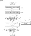
- the HMD of the present invention may be able to detect a location state of the connected digital device [S320].
- the location state may include a first state having the display unit of the digital device located in a preset view angle region of the HMD and a second state having the display unit of the digital device located outside the view angle region of the HMD.
- the view angle region is a preset region corresponding to eyes of a user who is wearing the HMD and may include a section within a predetermined angle range in front direction of the HMD.
- the present invention even if a direction (e.g., an azimuth angle) having the digital device located therein is changing while a distance between the digital device is maintained constant, it may be able to accurately detect a location state of the digital device using a plurality of the antennas provided to the HMD.
- a direction e.g., an azimuth angle
- the present invention may be able to detect a location state of the digital device using an image photographing sensor.
- the image photographing sensor detects an image within the preset view angle region of the HMD and may be then able to provide the detected image to the processor of the HMD.
- the processor may be able to detect whether a digital device (or, a display unit of the corresponding digital device) connected with the HMD is present within the view angle region of the HMD.
- the digital device connected with the HMD may be able to output a preset light pattern and the HMD is then able to detect the light pattern outputted from the digital device.
- the light pattern may include at least one of a temporal pattern and a spatial pattern.
- the light pattern may be outputted from the display unit of the digital device.
- the HMD may be able to detect the light pattern outputted from the digital device via the image photographing sensor. Otherwise, i.e., if the digital device connected with the HMD is not present within the view angle region of the HMD, the light pattern outputted from the digital device may not be detected via the image photographing sensor. Meanwhile, when a light pattern is outputted via the display unit of the digital device according to the embodiment of the present invention, even if the display unit of the corresponding digital device does not face a user despite that the digital device is present within the view angle region, the light pattern may not be detected.
- an HMD of the present invention may be able to detect a location state of the digital device.
- the light pattern may be outputted via the display unit of the digital device, by which the present invention may be non-limited.
- the digital device may be able to output a light pattern of itself irrespective of whether the digital device has performed the communication connection with the HMD.
- the HMD may be able to trigger whether to output a content of the digital device in accordance with a location state relative to that of the digital device.
- the HMD in the first state in which the display unit of the digital device is located within the view angle region of the HMD, the HMD does not output a currently displayed content of the digital device.
- the HMD in the second state in which the display unit of the digital device is not located within the view angle region of the HMD, the HMD may be able to output a currently displayed content of the digital device.
- the user in the second state in which a location of the digital device deviates from the view of the user wearing the HMD, the user may be able to be provided with the content of the digital device via the HMD.
- the user in the first state in which a location of the digital device lies within the view of the user wearing the HMD, the user may be able to be provided with the content via the digital device without interference via the display of the HMD.
- an HMD may be able to trigger whether to output a content of the digital device.
- the HMD may be able to output the content of the digital device.
- the HMD may be able to terminate the output of the content of the digital device.
- an HMD may be able to detect a real-time location state of a digital device while a communication connection is established between the HMD and the digital device. Based on the detected location state, it may be able to determine whether a content currently displayed by the digital device will be outputted to the HMD. If the detected location state is switched, it may be able to adjust whether to output the content of the digital device to the HMD based on the switched location state. If the communication connection with the digital device is terminated, the HMD may be able to terminate both of the job of detecting the location state of the digital device and the job of outputting the content of the digital device.
- the HMD preferentially determines whether the display unit of the corresponding digital device is present within the view angle region of the HMD based on the detected location state of the digital device [S430]. If the display unit of the digital device is present within the view angle region, the HMD of the present invention may not establish the communication connection with the digital device [S440]. On the contrary, if the display unit of the digital device is not present within the view angle region, the HMD may be able to establish the communication connection with the digital device [S442]. If the HMD establishes the communication connection with the digital device, it may be able to receive a currently displayed content of the digital device from the digital device [S444]. The HMD of the present invention may be then able to output the received content [S446].
- the switched location state after a detected location state of a digital device has been switched, if the switched location state is maintained over a preset time, it may be able to trigger whether to establish a communication connection between an HMD and the digital device.
- the location state of the digital device is switched into a second state from a first state in which the communication connection between the HMD and the digital device is not established, when the location state of the digital device is maintained in the second state over the preset time, it may be able to establish the communication connection between the HMD and the digital device.
- the HMD of the present invention determines whether the HMD is being paired with the digital device is ongoing [S450]. If the HMD is being paired with the digital device, the HMD goes back to the step S420 and then detects a location state of the paired digital device. If the pairing between the HMD and the digital device is terminated, the HMD may terminate the content output of the digital device.
- an HMD may be able to detect a real-time location state of a digital device while paired with the digital device. Based on the detected location state, it may be able to determine whether to establish a communication connection between the HMD and the digital device. If the detected location state is switched, it may be able to adjust whether to establish the communication connection between the HMD and the digital device based on the switched location state. If the pairing with the digital device is terminated, the HMD may be able to terminate both of the job of detecting the location state of the digital device and the job of outputting the content of the digital device.
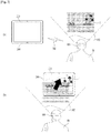
- FIGs. 5 to 7 are diagrams for one detailed examples of outputting a content 1 using an HMD 100 of the present invention.
- an HMD 100 is being paired with a digital device 200. Referring to FIGs. 5 to 7 , it may be able to control an output of a content 1 of the HMD 100 based on a location state of a digital device 200 with reference to the HMD 100, i.e., relative locations and directions between the HMD 100 and the digital device 200.
- FIG. 5 and FIG. 6 show a case that the location state of the digital device 200 is switched into a second state [ FIG. 5 (b) ] from a first state [ FIG. 5 (a) ] according to an embodiment of the present invention. In doing so, the content 1 currently displayed on the digital device 200 moves to the HMD 100 and may be then displayed on the HMD 100.
- the HMD 100 may be able to output the content 1.
- the HMD 100 has already established the communication connection with the digital device 200.
- the HMD 100 receives the content 1 from the digital device 200 via a network 300 by real time and may be then able to output the received content 1. Meanwhile, according to the embodiment of the present invention, the digital device 200 may stop displaying the content 1 in the second state in which the digital device 200 is located outside the view angle region 102 of the HMD 100.
- the HMD 100 may be able to output the content 1 after duration of the preset time from a time in which the location state of the digital device 200 was switched.
- the digital device 200 may be able to stop an output of the content 1 during the preset time from the time in which the location state of the digital device 200 was switched. After duration of the preset time, the digital device 200 may continue to output the content 1. For instance, if the content 1 is a video content and the location state of the digital device 200 is switched from the first state into the second state, the digital device 200 may be able to pause the output of the video content during a preset time.
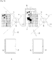
- a user 10 may look at a different spot instead of looking at a display unit 220 of a digital device 200 while wearing an HMD 100.
- the HMD 100 may be able to output a content 1.
- the HMD 100 may have established a communication connection with the digital device 200.
- the HMD 100 receives the content 1 from the digital device 200 by real time via a network 300 and may be then able to output the received content 1.
- the digital device 200 may pause a display of the content 1 in a second state in which the digital device 200 is located outside the view angle region 102 of the HMD 100.
- FIG. 8 shows that a location state of a digital device 200 is switched to a first state [ FIG. 8 (b) ] from a second state [ FIG. 8 (a) ] according to another embodiment of the present invention.
- the digital device 200 may be able to display a content 1 in both of the first state and the second state.
- an HMD 100 may be able to adjust whether to output the content 1 based on whether the digital device 200 located within the view angle region 102 of the HMD 100 displays the same content 1 of the HMD 100.
- FIG. 9 shows another embodiment of outputting a content 1 using an HMD 100 of the present invention.
- a location state of a digital device 200 is determined based on a location of the digital device 200 and a direction of a display unit 220 of the digital device 200.
- the location state may be determined based on whether the display unit 220 of the digital device 200 is located within a view angle region 102 of an HMD 100.
- it may be able to detect the location state of the According to one embodiment of the present invention, based on whether a light pattern 5 outputted by the digital device 200 is detected.
- the display unit 220 of the digital device 200 may be enabled to face the HMD 100. In doing so, the HMD 100 may be able to detect the light pattern 5 outputted by the digital device 200. If the light pattern 5 is detected, the HMD 100 recognizes a location state of the digital device 200 as a first state and does not output the content 1 of the digital device 200 correspondingly.
- the digital device shown in FIG. 9 (a) may be inverted.
- the display unit 220 of the digital device 200 may be set not to face the HMD 100.
- the HMD 100 may not be able to detect the light pattern 5 outputted by the digital device 200.
- the HMD 100 may recognize the location state of the digital device 200 shown in FIG. 9 (b) , in which the light pattern 5 is not detected, as a second state. Hence, the HMD 100 may be able to output the content 1 of the digital device 200.
- FIG. 10 shows a further embodiment of outputting a content 1 using an HMD 100 of the present invention.
- a display unit 220 of a digital device 200 in a second state in which a display unit 220 of a digital device 200 is not located within a view angle region 102 of an HMD 100, it may be able to detect whether a display unit 222 of at least one external device 202 is present in the view angle region 102. If it is detected that detect the display unit 222 of the at least one external device 202 is present in the view angle region 102, the display unit 222 of the corresponding external device 202 may be able to output a content 1 of the digital device 200.
- the external device 202 may be located within the view angle region 102 of the HMD 100.
- the HMD 100 may be able to detect the display unit 222 of the external device 202 located within the view angle region 102.
- the content 1 may be outputted to the display unit 222 of the corresponding external device 202.
- the detected external device 202 may be able to establish a communication connection with the digital device 200.
- the external device 202 may be able to receive the content 1 from the digital device 200 using the network 300. And, the received content 1 may be outputted to the display unit 222 of the external device 202.
- FIGs. 11 to 13 show further embodiments of the present invention.
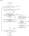
- FIG. 11 is a flowchart for a content outputting method using an HMD according to a further embodiment of the present invention.
- the processor 110 of the HMD 100 shown in FIG. 2 may be able to control the following operations of the respective steps shown in FIG. 1 . Details of the same or similar parts in the former embodiment described with reference to FIG. 3 shall be omitted in the description of the present embodiment with reference to FIG. 11 .
- an HMD of the present invention detects a first marker located within a view angle region of the HMD [S1110].
- a marker of the present invention is the identifier indicating content information and may include one of a bar code, a QR code, an RFID, a color code, an image code and the like.
- the HMD may be able to detect a location state of the first marker [S1120].
- the location state of the present invention may include a first sate having the first marker located within a preset view angle region of the HMD and a second state having the first marker not located within the view angle region.
- the HMD may be able to detect the location state of the first marker using an image photographing sensor.
- the image photographing sensor detects an image within the preset view angle region and may then provide the detected image to a processor of the HMD.
- the processor may be able to detect whether the first marker is present within the view angle region of the HMD based on the image detected by the image photographing sensor.
- the HMD keeps determining whether a marker within the view angle region is detected. In doing so, the HMD may be able to determine whether a second marker different from the first marker is detected within the view angle region [S1150]. If the second marker is not detected, the HMD goes back to the step S1120 and then continues the content output operation in accordance with the location state of the first marker. In particular, based on the location state of the first marker, the HMD may be able to trigger whether to output the content corresponding to the first marker. If the second marker is detected, the HMD terminates the content output operation in accordance with the location state of the first marker.
- the HMD may be able to detect the location state of the newly detected second marker and may be then able to perform a content output in accordance with the location state of the second marker by the same method mentioned in the foregoing description of the embodiment with reference to FIG. 11 .
- FIG. 12 and FIG. 13 show a detailed method of outputting a content using an HMD in accordance with the former embodiment shown in FIG. 11 .
- a user 10 may be able to watch a content 1 including a marker 5 while wearing an HMD 100.
- the content 1 may include an analog content instead of a digital content.
- the content 1 may include a partial or whole region of a book, a magazine, a newspaper, a photo or the like.
- the content 1 may include the marker 5 indicating the information on the corresponding content 1.
- the marker is located within a view angle region 102 of the HMD 100. And, the HMD 100 does not output the content 1.
- the user 10 may look at a different spot other than the content 1 while wearing the HMD 100.
- the marker 5 included in the content 1 may be located outside the view angle region 102 of the HMD 100.
- a location state of the marker 5 may be switched from a first state [ FIG. 12 ] to a second state [ FIG. 13 (a) ].
- the HMD 100 may be able to output the content 1 corresponding to the marker 5.
- the HMD 100 receives the content 1 corresponding to the marker 5 from a server (not shown in the drawing) via a network 300 and may be then able to output the received content.
- the user 10 may be able to look at the content 1 again while wearing the HMD 100.
- the marker 5 included in the content 1 may be located within the view angle region of the HMD 100.
- the location state of the marker 5 may be switched from the second state [ FIG. 13 (a) ] to the first state [ FIG. 13 (b) ].
- the HMD 100 may be able to terminate the output of the content 1 corresponding to the marker 5.
- the HDM 100 may be able to adjust whether to output the content 1 based on whether the content 1 located with the view angle region 102 of the HMD 100 is identical to the content 1 currently outputted by the HMD 100.
- the HMD 100 determines whether the content 1 having entered the view angle region 102 is identical to the content 1 currently outputted by the HMD 100. If the content 1 having entered the view angle region n102 is identical to the content 1 currently outputted by the HMD 100, referring to FIG. 13 (b) , the HMD 100 may be able to avoid the overlapping of the display of the content 1 by terminating the output of the content 1. Otherwise, i.e., if the content 1 having entered the view angle region 102 is not identical to the content 1 currently outputted by the HMD 100, the HMD 100 may not terminate the output of the content 1.
- a location state of a digital device may be determined based on eyes of a user who wears an HMD.
- the HMD of the present invention may further include an image photographing sensor configured to detect a position of the pupil of the user wearing the HMD and may be able to track eyes of the corresponding user using the image photographing sensor. Therefore, the location state of the digital device of the present invention may be determined based on whether a display unit of the digital device is located within a view angle region of the user wearing the HMD.
- the view angle region may include a region within a predetermined range corresponding to the eyes of the user wearing the HMD.
- the location state of the digital device may include a third state in which the display unit of the digital device is located within the view angle region of the user wearing the HMD and a fourth state in which the display unit of the digital device is not located within the view angle region of the user wearing the HMD.
- a location state of a marker may be also determined based on the eyes of the user wearing the HMD in the manner mentioned in the above description.
- HMD mentioned in the description of the present invention may be changeable with or replaceable by various devices for the purposes of the present invention.
- HMD of the present invention may include such a device, which is capable of providing a display by being put on a user, as EMD (eye mounted display), eyeglass, eyepiece, eyewear, HWD (head worn display) and the like.
- EMD eye mounted display
- eyeglass eyepiece
- eyewear eyewear
- HWD head worn display
- the HMD may be non-limited by the terminologies used for the description of the present invention.
Landscapes
- Engineering & Computer Science (AREA)
- Physics & Mathematics (AREA)
- Theoretical Computer Science (AREA)
- General Physics & Mathematics (AREA)
- General Engineering & Computer Science (AREA)
- Human Computer Interaction (AREA)
- Optics & Photonics (AREA)
- Controls And Circuits For Display Device (AREA)
- User Interface Of Digital Computer (AREA)
- Multimedia (AREA)
- Computer Hardware Design (AREA)
Claims (12)
- Verfahren zum Ausgeben eines Inhalts unter Verwendung einer kopfmontierten Anzeige (100), wobei das Verfahren umfasst:Durchführen einer Kopplung mit einer digitalen Vorrichtung (200), die mindestens eine Anzeigeeinheit aufweist, die zum Anzeigen des Inhalts konfiguriert ist;Erfassen eines Ortszustands der gekoppelten digitalen Vorrichtung (200), wobei der Ortszustand einen ersten Zustand, in dem sich eine Anzeigeeinheit der digitalen Vorrichtung (200) innerhalb eines voreingestellten Sichtwinkelbereichs der kopfmontierten Anzeige (100) befindet, und einen zweiten Zustand, in dem sich die Anzeigeeinheit der digitalen Vorrichtung nicht innerhalb des voreingestellten Sichtwinkelbereichs befindet, umfasst; undAusgeben des Inhalts, der aktuell in der digitalen Vorrichtung (200) angezeigt wird, an die kopfmontierte Anzeige (100) auf der Grundlage des erfassten Ortszustands; dadurch gekennzeichnet, dass:falls der erfasste Ortszustand den zweiten Zustand umfasst, Erfassen, ob eine Anzeigeeinheit aus mindestens einer externen Vorrichtung anwesend ist innerhalb des Sichtwinkelbereichs; undfalls die Anzeigeeinheit aus der mindestens einen externen Vorrichtung innerhalb des Sichtwinkelbereichs erfasst wird, Ausgeben des Inhalts an die Anzeigeeinheit der entsprechenden externen Vorrichtung.
- Verfahren nach Anspruch 1, wobei der Ausgabeschritt weiter Ausgeben des Inhalts an die kopfmontierte Anzeige (100) umfasst, falls der erfasste Ortszustand der zweite Zustand ist.
- Verfahren nach Anspruch 2, wobei der Ausgabeschritt weiter die folgenden Schritte umfasst:Herstellen einer Kommunikationsverbindung mit der digitalen Vorrichtung (200);Empfangen des Inhalts, der aktuell auf der mit der zur Kommunikation verbundenen digitalen Vorrichtung (200) angezeigt wird; undAusgeben des empfangenen Inhalts an die kopfmontierte Anzeige (100).
- Verfahren nach Anspruch 1, weiter umfassend den Schritt des, falls der erfasste Ortszustand von dem zweiten Zustand in den ersten Zustand geschaltet wird, Bestimmens, ob der Inhalt, der aktuell in der digitalen Vorrichtung (200) angezeigt wird, identisch ist mit dem Inhalt, der aktuell an die kopfmontierte Anzeige (100) ausgegeben wird, wobei, falls der Inhalt, der aktuell in der digitalen Vorrichtung (200) angezeigt wird, identisch ist mit dem Inhalt, der aktuell an die kopfmontierte Anzeige (100) ausgegeben wird, der Ausgabeschritt Beenden der Ausgabe an die kopfmontierte Anzeige (100) umfasst.
- Verfahren nach Anspruch 1, wobei der Ausgabeschritt den Schritt des, falls der erfasste Ortszustand von dem ersten Zustand in den zweiten Zustand geschaltet wird, Ausgebens des Inhalts in einer Weise umfasst, dass der Inhalt gleitet, um sich von einer Seite in einen Mittelbereich zu bewegen, in dem die Anzeigeeinheit der digitalen Vorrichtung (200) von dem Ort des Sichtwinkelbereichs abweicht.
- Computerprogramm, umfassend Anweisungen, die, wenn auf einer Computervorrichtung ausgeführt, das Verfahren nach einem der Ansprüche 1 bis 5 implementieren.
- Kopfmontierte Anzeige (100), umfassend:einen Prozessor, der zum Steuern eines Betriebs der kopfmontierten Anzeige (100) konfiguriert ist;eine Anzeigeeinheit, die zum Ausgeben eines Bildes auf der Grundlage eines durch den Prozessor gegebenen Befehls konfiguriert ist; undeine Kommunikationseinheit, die zum Senden und Empfangen von Daten mit mindestens einer digitalen Vorrichtung auf der Grundlage des durch den Prozessor gegebenen Befehls konfiguriert ist,wobei der Prozessor weiter konfiguriert ist zum:Durchführen einer Kopplung mit einer digitalen Vorrichtung (200), die mindestens eine Anzeigeeinheit aufweist, die konfiguriert ist, um den Inhalt anzuzeigen,Erfassen eines Ortszustands der gekoppelten digitalen Vorrichtung (200), wobei der Ortszustand einen ersten Zustand, in dem sich die Anzeigeeinheit der digitalen Vorrichtung innerhalb eines voreingestellten Sichtwinkelbereichs der kopfmontierten Anzeige (100) befindet, und einen zweiten Zustand, in dem sich die Anzeigeeinheit der digitalen Vorrichtung (200) nicht innerhalb des Sichtwinkelbereichs befindet, umfasst, undAusgeben des aktuell in der digitalen Vorrichtung (200) angezeigten Inhalts an die Anzeigeeinheit der kopfmontierten Anzeige (100) auf der Grundlage des erfassten Ortszustands; und dadurch gekennzeichnet, dass der Prozessor so konfiguriert ist, dass:
falls der erfasste Ortszustand den zweiten Zustand umfasst, es erfasst wird, ob eine Anzeigeeinheit aus mindestens einer externen Vorrichtung innerhalb des Sichtwinkelbereichs anwesend ist und wobei, falls die Anzeigeeinheit aus der mindestens einen externen Vorrichtung innerhalb des Sichtwinkelbereichs erfasst wird, der Inhalt an die Anzeigeeinheit der entsprechenden externen Vorrichtung ausgegeben wird. - Kopfmontierte Anzeige (100) nach Anspruch 7, wobei, falls der erfasste Ortszustand der zweite Zustand ist, der Inhalt an die Anzeigeeinheit der kopfmontierten Anzeige (100) ausgegeben wird.
- Kopfmontierte Anzeige (100) nach Anspruch 8, wobei die kopfmontierte Anzeige (100) eine Kommunikationsverbindung mit der digitalen Vorrichtung (200) herstellt, den Inhalt, der aktuell auf der mit der zur Kommunikation verbundenen digitalen Vorrichtung angezeigt wird, empfängt, und den empfangenen Inhalt an die Anzeigeeinheit der kopfmontierten Anzeige (100) ausgibt.
- Kopfmontierte Anzeige (100) nach Anspruch 7, wobei, falls der erfasste Ortszustand von dem zweiten Zustand in den ersten Zustand geschaltet wird, der Prozessor bestimmt, ob der Inhalt, der aktuell in der digitalen Vorrichtung (200) angezeigt wird, identisch ist mit dem Inhalt, der aktuell an die kopfmontierte Anzeige (100) ausgegeben wird, und wobei, falls der Inhalt, der aktuell in der digitalen Vorrichtung (200) angezeigt wird, identisch ist mit dem Inhalt, der aktuell an die kopfmontierte Anzeige (100) ausgegeben wird, der Prozessor die Ausgabe an die kopfmontierte Anzeige (100) beendet.
- Kopfmontierte Anzeige (100) nach Anspruch 7, wobei, falls der erfasste Ortszustand von dem ersten Zustand in den zweiten Zustand geschaltet wird, der Inhalt in einer Weise ausgegeben wird, dass der Inhalt gleitet, um sich von einer Seite in einen Mittelbereich zu bewegen, in dem die Anzeigeeinheit der digitalen Vorrichtung (200) von dem Ort des Sichtwinkelbereichs abweicht.
- Kopfmontierte Anzeige (100) nach Anspruch 7, wobei die Kommunikationseinheit eine Vielzahl von Antennen umfasst und wobei der Prozessor den Ortszustand erfasst unter Verwendung von Signalen, die mit der digitalen Vorrichtung (200) gesendet und empfangen werden durch eine Vielzahl von Antennen, eingeschlossen in der kopfmontierten Anzeige (100).
Applications Claiming Priority (3)
| Application Number | Priority Date | Filing Date | Title |
|---|---|---|---|
| KR1020120077352A KR101861380B1 (ko) | 2012-07-16 | 2012-07-16 | 헤드 마운트 디스플레이를 이용한 컨텐츠 출력 방법 및 이를 위한 헤드 마운트 디스플레이 |
| PCT/KR2012/006344 WO2014014155A1 (en) | 2012-07-16 | 2012-08-09 | A head mounted dipslay and method of outputting a content using the same |
| EP12881212.0A EP2872945B1 (de) | 2012-07-16 | 2012-08-09 | Kopfmontierte anzeige und verfahren zur ausgabe von inhalten damit |
Related Parent Applications (2)
| Application Number | Title | Priority Date | Filing Date |
|---|---|---|---|
| EP12881212.0A Division EP2872945B1 (de) | 2012-07-16 | 2012-08-09 | Kopfmontierte anzeige und verfahren zur ausgabe von inhalten damit |
| EP12881212.0A Division-Into EP2872945B1 (de) | 2012-07-16 | 2012-08-09 | Kopfmontierte anzeige und verfahren zur ausgabe von inhalten damit |
Publications (2)
| Publication Number | Publication Date |
|---|---|
| EP3309601A1 EP3309601A1 (de) | 2018-04-18 |
| EP3309601B1 true EP3309601B1 (de) | 2019-03-20 |
Family
ID=48094858
Family Applications (2)
| Application Number | Title | Priority Date | Filing Date |
|---|---|---|---|
| EP12881212.0A Active EP2872945B1 (de) | 2012-07-16 | 2012-08-09 | Kopfmontierte anzeige und verfahren zur ausgabe von inhalten damit |
| EP17197917.2A Active EP3309601B1 (de) | 2012-07-16 | 2012-08-09 | Kopfmontierte anzeige und verfahren zur ausgabe von inhalten damit |
Family Applications Before (1)
| Application Number | Title | Priority Date | Filing Date |
|---|---|---|---|
| EP12881212.0A Active EP2872945B1 (de) | 2012-07-16 | 2012-08-09 | Kopfmontierte anzeige und verfahren zur ausgabe von inhalten damit |
Country Status (4)
| Country | Link |
|---|---|
| US (3) | US8427396B1 (de) |
| EP (2) | EP2872945B1 (de) |
| KR (1) | KR101861380B1 (de) |
| WO (1) | WO2014014155A1 (de) |
Families Citing this family (155)
| Publication number | Priority date | Publication date | Assignee | Title |
|---|---|---|---|---|
| US9158116B1 (en) | 2014-04-25 | 2015-10-13 | Osterhout Group, Inc. | Temple and ear horn assembly for headworn computer |
| US9400390B2 (en) | 2014-01-24 | 2016-07-26 | Osterhout Group, Inc. | Peripheral lighting for head worn computing |
| US9366867B2 (en) | 2014-07-08 | 2016-06-14 | Osterhout Group, Inc. | Optical systems for see-through displays |
| US9965681B2 (en) | 2008-12-16 | 2018-05-08 | Osterhout Group, Inc. | Eye imaging in head worn computing |
| US20150277120A1 (en) | 2014-01-21 | 2015-10-01 | Osterhout Group, Inc. | Optical configurations for head worn computing |
| US9952664B2 (en) | 2014-01-21 | 2018-04-24 | Osterhout Group, Inc. | Eye imaging in head worn computing |
| US9298007B2 (en) | 2014-01-21 | 2016-03-29 | Osterhout Group, Inc. | Eye imaging in head worn computing |
| US9229233B2 (en) | 2014-02-11 | 2016-01-05 | Osterhout Group, Inc. | Micro Doppler presentations in head worn computing |
| US9715112B2 (en) | 2014-01-21 | 2017-07-25 | Osterhout Group, Inc. | Suppression of stray light in head worn computing |
| US20150205111A1 (en) | 2014-01-21 | 2015-07-23 | Osterhout Group, Inc. | Optical configurations for head worn computing |
| US20180048750A1 (en) * | 2012-06-15 | 2018-02-15 | Muzik, Llc | Audio/video wearable computer system with integrated projector |
| KR101969351B1 (ko) * | 2012-09-10 | 2019-04-16 | 엘지전자 주식회사 | 헤드 마운트 디스플레이 및 그 출력 제어 방법 |
| US9791921B2 (en) * | 2013-02-19 | 2017-10-17 | Microsoft Technology Licensing, Llc | Context-aware augmented reality object commands |
| KR102063076B1 (ko) * | 2013-07-10 | 2020-01-07 | 엘지전자 주식회사 | 모바일 디바이스, 헤드 마운트 디스플레이 및 제어 방법 |
| KR102081934B1 (ko) * | 2013-08-28 | 2020-02-26 | 엘지전자 주식회사 | 헤드 마운트 디스플레이 디바이스 및 그 제어 방법 |
| WO2015031168A1 (en) * | 2013-08-28 | 2015-03-05 | Qualcomm Incorporated | Dynamic display markers |
| US20150062158A1 (en) | 2013-08-28 | 2015-03-05 | Qualcomm Incorporated | Integration of head mounted displays with public display devices |
| KR102105520B1 (ko) * | 2013-11-12 | 2020-04-28 | 삼성전자주식회사 | 디스플레이 링크 기능을 수행하는 전자 장치 및 방법 |
| US9448621B2 (en) * | 2013-12-20 | 2016-09-20 | Nokia Technologies Oy | Causation of display of information on a see through display |
| EP2894508A1 (de) * | 2013-12-31 | 2015-07-15 | Thomson Licensing | Verfahren zur Anzeige von Inhalt entweder über eine kopfmontierte Anzeige oder eine Anzeigevorrichtung, entsprechende kopfmontierte Anzeigevorrichtung und Computerprogrammprodukt |
| US10001645B2 (en) * | 2014-01-17 | 2018-06-19 | Sony Interactive Entertainment America Llc | Using a second screen as a private tracking heads-up display |
| US9529195B2 (en) | 2014-01-21 | 2016-12-27 | Osterhout Group, Inc. | See-through computer display systems |
| US9448409B2 (en) | 2014-11-26 | 2016-09-20 | Osterhout Group, Inc. | See-through computer display systems |
| US20160019715A1 (en) | 2014-07-15 | 2016-01-21 | Osterhout Group, Inc. | Content presentation in head worn computing |
| US11227294B2 (en) | 2014-04-03 | 2022-01-18 | Mentor Acquisition One, Llc | Sight information collection in head worn computing |
| US9366868B2 (en) | 2014-09-26 | 2016-06-14 | Osterhout Group, Inc. | See-through computer display systems |
| US9829707B2 (en) | 2014-08-12 | 2017-11-28 | Osterhout Group, Inc. | Measuring content brightness in head worn computing |
| US9299194B2 (en) | 2014-02-14 | 2016-03-29 | Osterhout Group, Inc. | Secure sharing in head worn computing |
| US10254856B2 (en) | 2014-01-17 | 2019-04-09 | Osterhout Group, Inc. | External user interface for head worn computing |
| US9671613B2 (en) | 2014-09-26 | 2017-06-06 | Osterhout Group, Inc. | See-through computer display systems |
| US9939934B2 (en) | 2014-01-17 | 2018-04-10 | Osterhout Group, Inc. | External user interface for head worn computing |
| US10684687B2 (en) | 2014-12-03 | 2020-06-16 | Mentor Acquisition One, Llc | See-through computer display systems |
| US9810906B2 (en) | 2014-06-17 | 2017-11-07 | Osterhout Group, Inc. | External user interface for head worn computing |
| US10191279B2 (en) | 2014-03-17 | 2019-01-29 | Osterhout Group, Inc. | Eye imaging in head worn computing |
| US9841599B2 (en) | 2014-06-05 | 2017-12-12 | Osterhout Group, Inc. | Optical configurations for head-worn see-through displays |
| US11103122B2 (en) | 2014-07-15 | 2021-08-31 | Mentor Acquisition One, Llc | Content presentation in head worn computing |
| US10649220B2 (en) | 2014-06-09 | 2020-05-12 | Mentor Acquisition One, Llc | Content presentation in head worn computing |
| US9575321B2 (en) | 2014-06-09 | 2017-02-21 | Osterhout Group, Inc. | Content presentation in head worn computing |
| US20150228119A1 (en) | 2014-02-11 | 2015-08-13 | Osterhout Group, Inc. | Spatial location presentation in head worn computing |
| US20150277118A1 (en) | 2014-03-28 | 2015-10-01 | Osterhout Group, Inc. | Sensor dependent content position in head worn computing |
| US9594246B2 (en) | 2014-01-21 | 2017-03-14 | Osterhout Group, Inc. | See-through computer display systems |
| US9746686B2 (en) | 2014-05-19 | 2017-08-29 | Osterhout Group, Inc. | Content position calibration in head worn computing |
| US9310610B2 (en) | 2014-01-21 | 2016-04-12 | Osterhout Group, Inc. | See-through computer display systems |
| US12093453B2 (en) | 2014-01-21 | 2024-09-17 | Mentor Acquisition One, Llc | Eye glint imaging in see-through computer display systems |
| US11892644B2 (en) | 2014-01-21 | 2024-02-06 | Mentor Acquisition One, Llc | See-through computer display systems |
| US11487110B2 (en) | 2014-01-21 | 2022-11-01 | Mentor Acquisition One, Llc | Eye imaging in head worn computing |
| US11737666B2 (en) | 2014-01-21 | 2023-08-29 | Mentor Acquisition One, Llc | Eye imaging in head worn computing |
| US9494800B2 (en) | 2014-01-21 | 2016-11-15 | Osterhout Group, Inc. | See-through computer display systems |
| US12105281B2 (en) | 2014-01-21 | 2024-10-01 | Mentor Acquisition One, Llc | See-through computer display systems |
| US9651788B2 (en) | 2014-01-21 | 2017-05-16 | Osterhout Group, Inc. | See-through computer display systems |
| US9651784B2 (en) | 2014-01-21 | 2017-05-16 | Osterhout Group, Inc. | See-through computer display systems |
| US9532714B2 (en) | 2014-01-21 | 2017-01-03 | Osterhout Group, Inc. | Eye imaging in head worn computing |
| US9836122B2 (en) | 2014-01-21 | 2017-12-05 | Osterhout Group, Inc. | Eye glint imaging in see-through computer display systems |
| US9766463B2 (en) | 2014-01-21 | 2017-09-19 | Osterhout Group, Inc. | See-through computer display systems |
| US9740280B2 (en) | 2014-01-21 | 2017-08-22 | Osterhout Group, Inc. | Eye imaging in head worn computing |
| US20150205135A1 (en) | 2014-01-21 | 2015-07-23 | Osterhout Group, Inc. | See-through computer display systems |
| US11669163B2 (en) | 2014-01-21 | 2023-06-06 | Mentor Acquisition One, Llc | Eye glint imaging in see-through computer display systems |
| US9753288B2 (en) | 2014-01-21 | 2017-09-05 | Osterhout Group, Inc. | See-through computer display systems |
| US9846308B2 (en) | 2014-01-24 | 2017-12-19 | Osterhout Group, Inc. | Haptic systems for head-worn computers |
| US20150241963A1 (en) | 2014-02-11 | 2015-08-27 | Osterhout Group, Inc. | Eye imaging in head worn computing |
| US9852545B2 (en) | 2014-02-11 | 2017-12-26 | Osterhout Group, Inc. | Spatial location presentation in head worn computing |
| US9401540B2 (en) | 2014-02-11 | 2016-07-26 | Osterhout Group, Inc. | Spatial location presentation in head worn computing |
| US12112089B2 (en) | 2014-02-11 | 2024-10-08 | Mentor Acquisition One, Llc | Spatial location presentation in head worn computing |
| US9691181B2 (en) * | 2014-02-24 | 2017-06-27 | Sony Interactive Entertainment Inc. | Methods and systems for social sharing head mounted display (HMD) content with a second screen |
| US20150245163A1 (en) * | 2014-02-25 | 2015-08-27 | Sony Corporation | Proximity detection of candidate companion display device in same room as primary display using wi-fi or bluetooth signal strength |
| US9483997B2 (en) * | 2014-03-10 | 2016-11-01 | Sony Corporation | Proximity detection of candidate companion display device in same room as primary display using infrared signaling |
| JP2015176186A (ja) * | 2014-03-13 | 2015-10-05 | ソニー株式会社 | 情報処理装置、情報処理方法、及び情報処理システム |
| KR102374584B1 (ko) * | 2014-03-21 | 2022-03-16 | 삼성전자주식회사 | 영상을 디스플레이 하는 방법 및 디바이스 |
| US20160187651A1 (en) | 2014-03-28 | 2016-06-30 | Osterhout Group, Inc. | Safety for a vehicle operator with an hmd |
| WO2015163529A1 (en) * | 2014-04-23 | 2015-10-29 | Lg Electronics Inc. | Head mounted display device displaying thumbnail image and method of controlling therefor |
| KR102246553B1 (ko) | 2014-04-24 | 2021-04-30 | 엘지전자 주식회사 | Hmd 및 그 제어 방법 |
| WO2015163539A1 (en) * | 2014-04-24 | 2015-10-29 | Lg Electronics Inc. | Head mounted display and method for controlling the same |
| US9672210B2 (en) | 2014-04-25 | 2017-06-06 | Osterhout Group, Inc. | Language translation with head-worn computing |
| US9423842B2 (en) | 2014-09-18 | 2016-08-23 | Osterhout Group, Inc. | Thermal management for head-worn computer |
| US9651787B2 (en) | 2014-04-25 | 2017-05-16 | Osterhout Group, Inc. | Speaker assembly for headworn computer |
| US10853589B2 (en) | 2014-04-25 | 2020-12-01 | Mentor Acquisition One, Llc | Language translation with head-worn computing |
| US20150309534A1 (en) | 2014-04-25 | 2015-10-29 | Osterhout Group, Inc. | Ear horn assembly for headworn computer |
| US20160137312A1 (en) | 2014-05-06 | 2016-05-19 | Osterhout Group, Inc. | Unmanned aerial vehicle launch system |
| KR102257621B1 (ko) | 2014-05-19 | 2021-05-28 | 엘지전자 주식회사 | 썸네일 이미지를 디스플레이 하는 헤드 마운티드 디스플레이 디바이스 및 그 제어 방법 |
| KR102229890B1 (ko) | 2014-05-30 | 2021-03-19 | 삼성전자주식회사 | 데이터 처리 방법 및 그 전자 장치 |
| US10663740B2 (en) | 2014-06-09 | 2020-05-26 | Mentor Acquisition One, Llc | Content presentation in head worn computing |
| US9092898B1 (en) | 2014-07-03 | 2015-07-28 | Federico Fraccaroli | Method, system and apparatus for the augmentation of radio emissions |
| KR102251710B1 (ko) * | 2014-11-04 | 2021-05-14 | 넥시스 주식회사 | 글라스형 웨어러블 디바이스를 이용한 외부디바이스 내 콘텐츠 관리 시스템, 방법 및 컴퓨터로 독출 가능한 기록매체 |
| WO2016021252A1 (ja) * | 2014-08-05 | 2016-02-11 | ソニー株式会社 | 情報処理装置及び情報処理方法、並びに画像表示システム |
| AU2015303267A1 (en) | 2014-08-11 | 2016-07-07 | Vr Coaster Gmbh & Co. Kg | Method for operating a device, in particular an amusement ride, transport means, a fitness device or similar |
| KR102232419B1 (ko) * | 2014-08-26 | 2021-03-26 | 엘지전자 주식회사 | 웨어러블 디스플레이 디바이스 및 그 제어 방법 |
| KR102271833B1 (ko) | 2014-09-01 | 2021-07-01 | 삼성전자주식회사 | 전자 장치, 그 제어 방법 및 기록 매체 |
| KR102243656B1 (ko) * | 2014-09-26 | 2021-04-23 | 엘지전자 주식회사 | 모바일 디바이스, hmd 및 시스템 |
| RU2017115844A (ru) * | 2014-10-06 | 2018-11-12 | Конинклейке Филипс Н.В. | Система подключения |
| KR102265086B1 (ko) | 2014-11-07 | 2021-06-15 | 삼성전자 주식회사 | 정보를 공유하기 위한 가상 환경 |
| US9684172B2 (en) | 2014-12-03 | 2017-06-20 | Osterhout Group, Inc. | Head worn computer display systems |
| GB2533098B (en) * | 2014-12-09 | 2016-12-14 | Ibm | Automated management of confidential data in cloud environments |
| USD743963S1 (en) | 2014-12-22 | 2015-11-24 | Osterhout Group, Inc. | Air mouse |
| USD751552S1 (en) | 2014-12-31 | 2016-03-15 | Osterhout Group, Inc. | Computer glasses |
| USD753114S1 (en) | 2015-01-05 | 2016-04-05 | Osterhout Group, Inc. | Air mouse |
| US9933985B2 (en) * | 2015-01-20 | 2018-04-03 | Qualcomm Incorporated | Systems and methods for managing content presentation involving a head mounted display and a presentation device |
| KR102274743B1 (ko) * | 2015-01-30 | 2021-07-08 | 삼성전자주식회사 | 전자 장치 및 전자 장치의 화면 영역 처리 방법 |
| KR101564964B1 (ko) * | 2015-02-05 | 2015-11-02 | 계명대학교 산학협력단 | 가상현실 멀미를 감소시키는 전기 자극 헤드 마운트 디스플레이 장치 |
| US10878775B2 (en) | 2015-02-17 | 2020-12-29 | Mentor Acquisition One, Llc | See-through computer display systems |
| US20160239985A1 (en) | 2015-02-17 | 2016-08-18 | Osterhout Group, Inc. | See-through computer display systems |
| WO2016141263A1 (en) * | 2015-03-04 | 2016-09-09 | Oculus Vr, Llc | Sparse projection for a virtual reality system |
| US10591729B2 (en) * | 2015-05-29 | 2020-03-17 | Kyocera Corporation | Wearable device |
| US10139966B2 (en) | 2015-07-22 | 2018-11-27 | Osterhout Group, Inc. | External user interface for head worn computing |
| JP6686319B2 (ja) * | 2015-08-04 | 2020-04-22 | 富士通株式会社 | 画像投影装置及び画像表示システム |
| JP6529383B2 (ja) * | 2015-08-11 | 2019-06-12 | 京セラ株式会社 | ウェアラブル装置及び出力システム |
| US10515482B2 (en) | 2015-08-24 | 2019-12-24 | Pcms Holdings, Inc. | Systems and methods for enhancing augmented reality experience with dynamic output mapping |
| US9865091B2 (en) * | 2015-09-02 | 2018-01-09 | Microsoft Technology Licensing, Llc | Localizing devices in augmented reality environment |
| GB2542434A (en) | 2015-09-21 | 2017-03-22 | Figment Productions Ltd | A System for Providing a Virtual Reality Experience |
| WO2017062289A1 (en) | 2015-10-08 | 2017-04-13 | Pcms Holdings, Inc. | Methods and systems of automatic calibration for dynamic display configurations |
| CN105657438A (zh) * | 2015-11-09 | 2016-06-08 | 乐视致新电子科技(天津)有限公司 | 一种全景直播视频资源的处理方法及装置 |
| US10591728B2 (en) | 2016-03-02 | 2020-03-17 | Mentor Acquisition One, Llc | Optical systems for head-worn computers |
| US10850116B2 (en) | 2016-12-30 | 2020-12-01 | Mentor Acquisition One, Llc | Head-worn therapy device |
| US10667981B2 (en) | 2016-02-29 | 2020-06-02 | Mentor Acquisition One, Llc | Reading assistance system for visually impaired |
| US9880441B1 (en) | 2016-09-08 | 2018-01-30 | Osterhout Group, Inc. | Electrochromic systems for head-worn computer systems |
| US9826299B1 (en) | 2016-08-22 | 2017-11-21 | Osterhout Group, Inc. | Speaker systems for head-worn computer systems |
| CN105847627B (zh) * | 2016-03-30 | 2018-11-23 | 北京小米移动软件有限公司 | 一种显示图像数据的方法和装置 |
| US9910284B1 (en) | 2016-09-08 | 2018-03-06 | Osterhout Group, Inc. | Optical systems for head-worn computers |
| US10684478B2 (en) | 2016-05-09 | 2020-06-16 | Mentor Acquisition One, Llc | User interface systems for head-worn computers |
| US10466491B2 (en) | 2016-06-01 | 2019-11-05 | Mentor Acquisition One, Llc | Modular systems for head-worn computers |
| US10824253B2 (en) | 2016-05-09 | 2020-11-03 | Mentor Acquisition One, Llc | User interface systems for head-worn computers |
| US10210661B2 (en) | 2016-04-25 | 2019-02-19 | Microsoft Technology Licensing, Llc | Location-based holographic experience |
| US10748339B2 (en) | 2016-06-03 | 2020-08-18 | A Big Chunk Of Mud Llc | System and method for implementing computer-simulated reality interactions between users and publications |
| KR20180002255A (ko) * | 2016-06-29 | 2018-01-08 | 엘지전자 주식회사 | 글래스 타입의 이동 단말기 |
| US10690936B2 (en) | 2016-08-29 | 2020-06-23 | Mentor Acquisition One, Llc | Adjustable nose bridge assembly for headworn computer |
| JP2018036993A (ja) * | 2016-09-02 | 2018-03-08 | オリンパス株式会社 | 表示システム、携帯情報機器、ウエラブル型端末、情報表示方法およびプログラム |
| USD840395S1 (en) | 2016-10-17 | 2019-02-12 | Osterhout Group, Inc. | Head-worn computer |
| JP2018078475A (ja) * | 2016-11-10 | 2018-05-17 | 富士通株式会社 | 制御プログラム、制御方法および制御装置 |
| KR102739220B1 (ko) | 2016-12-23 | 2024-12-05 | 삼성전자주식회사 | 3차원 컨텐츠의 썸네일 관리 방법 및 그 장치 |
| USD864959S1 (en) | 2017-01-04 | 2019-10-29 | Mentor Acquisition One, Llc | Computer glasses |
| JP6792699B2 (ja) * | 2017-03-13 | 2020-11-25 | 三井化学株式会社 | アイウェア |
| CA3057564C (en) | 2017-03-22 | 2023-10-31 | A Big Chunk Of Mud Llc | Convertible satchel with integrated head-mounted display |
| US11409105B2 (en) | 2017-07-24 | 2022-08-09 | Mentor Acquisition One, Llc | See-through computer display systems |
| US10578869B2 (en) | 2017-07-24 | 2020-03-03 | Mentor Acquisition One, Llc | See-through computer display systems with adjustable zoom cameras |
| US10422995B2 (en) | 2017-07-24 | 2019-09-24 | Mentor Acquisition One, Llc | See-through computer display systems with stray light management |
| US10969584B2 (en) | 2017-08-04 | 2021-04-06 | Mentor Acquisition One, Llc | Image expansion optic for head-worn computer |
| US20190129607A1 (en) * | 2017-11-02 | 2019-05-02 | Samsung Electronics Co., Ltd. | Method and device for performing remote control |
| JP7035510B2 (ja) * | 2017-12-22 | 2022-03-15 | セイコーエプソン株式会社 | 表示システム、及び、表示システムの制御方法 |
| KR102013154B1 (ko) * | 2018-02-02 | 2019-08-22 | 강근원 | 장거리 이동시 헤드 마운티드 디스플레이를 이용한 콘텐츠 서비스 방법 및 컴퓨터 프로그램 |
| US10748021B2 (en) | 2018-05-11 | 2020-08-18 | Samsung Electronics Co., Ltd. | Method of analyzing objects in images recorded by a camera of a head mounted device |
| US11378805B2 (en) * | 2018-06-25 | 2022-07-05 | Maxell, Ltd. | Head-mounted display, head-mounted display linking system, and method for same |
| CN113273184B (zh) | 2018-11-30 | 2025-01-03 | Pcms控股公司 | 将3d对象镜像到光场显示器的方法 |
| US10852819B2 (en) * | 2019-01-11 | 2020-12-01 | Dell Products, L.P. | Systems and methods for eye-gaze tracking (EGT) handoff |
| JP6997129B2 (ja) * | 2019-03-28 | 2022-01-17 | ファナック株式会社 | 制御システム |
| US11960091B2 (en) | 2020-05-27 | 2024-04-16 | Telefonaktiebolaget Lm Ericsson (Publ) | Method and device for controlling display of content |
| KR102290328B1 (ko) * | 2020-11-16 | 2021-08-18 | 코리아에프티 주식회사 | 영상 출력 장치 |
| JP7140890B1 (ja) * | 2021-06-18 | 2022-09-21 | 株式会社ドワンゴ | 視聴者端末、視聴者端末の制御方法、視聴者端末の制御プログラム、および、記録媒体 |
| DE102021206568A1 (de) | 2021-06-24 | 2022-12-29 | Siemens Healthcare Gmbh | Darstellungsvorrichtung zur Anzeige einer graphischen Darstellung einer erweiterten Realität |
| EP4369721B1 (de) | 2021-11-29 | 2025-09-03 | Samsung Electronics Co., Ltd. | Elektronische vorrichtung zur bereitstellung von inhalt in zusammenhang mit einer externen anzeigevorrichtung und inhaltsbereitstellungsverfahren dafür |
| JP7642872B2 (ja) * | 2021-12-22 | 2025-03-10 | マクセル株式会社 | ヘッドマウントディスプレイ装置 |
| US11935201B2 (en) * | 2022-04-28 | 2024-03-19 | Dell Products Lp | Method and apparatus for using physical devices in extended reality environments |
| JP2024031113A (ja) * | 2022-08-25 | 2024-03-07 | 株式会社ソニー・インタラクティブエンタテインメント | 情報処理装置および画像生成方法 |
| JP2024052410A (ja) * | 2022-09-30 | 2024-04-11 | 富士フイルム株式会社 | プロセッサ、情報処理方法、及び情報処理プログラム |
| CN115633244B (zh) * | 2022-10-17 | 2023-06-30 | 元化智能科技(深圳)有限公司 | 图像数据传输方法和图像数据传输设备 |
| CN115942322B (zh) * | 2023-02-15 | 2023-06-06 | 北京秒信科技有限公司 | 一种骚扰短信拦截方法及系统 |
| US20250303291A1 (en) * | 2024-04-01 | 2025-10-02 | Sony Interactive Entertainment Inc. | Enabling the tracking of a remote-play client in virtual reality without additional sensors |
Family Cites Families (25)
| Publication number | Priority date | Publication date | Assignee | Title |
|---|---|---|---|---|
| JP3407383B2 (ja) * | 1993-06-15 | 2003-05-19 | オリンパス光学工業株式会社 | 頭部装着型ディスプレイシステム |
| JP3872100B2 (ja) * | 1993-08-12 | 2007-01-24 | セイコーエプソン株式会社 | 頭部搭載型の画像表示装置 |
| US6061064A (en) * | 1993-08-31 | 2000-05-09 | Sun Microsystems, Inc. | System and method for providing and using a computer user interface with a view space having discrete portions |
| JP2000347596A (ja) * | 1998-08-31 | 2000-12-15 | Semiconductor Energy Lab Co Ltd | 携帯情報処理システム |
| JP2000194726A (ja) * | 1998-10-19 | 2000-07-14 | Sony Corp | 情報処理装置及び方法、情報処理システム並びに提供媒体 |
| JP4178697B2 (ja) | 1999-11-18 | 2008-11-12 | ソニー株式会社 | 携帯型情報処理端末、情報入出力システム及び情報入出力方法 |
| US7215322B2 (en) * | 2001-05-31 | 2007-05-08 | Siemens Corporate Research, Inc. | Input devices for augmented reality applications |
| US7190331B2 (en) * | 2002-06-06 | 2007-03-13 | Siemens Corporate Research, Inc. | System and method for measuring the registration accuracy of an augmented reality system |
| JP2004127024A (ja) * | 2002-10-03 | 2004-04-22 | Canon Inc | 複合現実感システム用コンテンツ保護装置及び保護方法 |
| US7331929B2 (en) * | 2004-10-01 | 2008-02-19 | General Electric Company | Method and apparatus for surgical operating room information display gaze detection and user prioritization for control |
| JP2006267604A (ja) * | 2005-03-24 | 2006-10-05 | Canon Inc | 複合情報表示装置 |
| US8179423B2 (en) * | 2005-08-22 | 2012-05-15 | Ricoh Company, Ltd. | Image display system, an image display method, a coding method, and a printed matter for stereoscopic viewing |
| US20070233759A1 (en) | 2006-03-28 | 2007-10-04 | The Regents Of The University Of California | Platform for seamless multi-device interactive digital content |
| JP2009245390A (ja) * | 2008-03-31 | 2009-10-22 | Brother Ind Ltd | 表示処理装置及び表示処理システム |
| JP5156571B2 (ja) * | 2008-10-10 | 2013-03-06 | キヤノン株式会社 | 画像処理装置、画像処理方法 |
| US20110291916A1 (en) * | 2008-12-10 | 2011-12-01 | Frank Arndt | Method for transmitting an image from a first control unit to a second control unit and output unit |
| US8913009B2 (en) | 2010-02-03 | 2014-12-16 | Nintendo Co., Ltd. | Spatially-correlated multi-display human-machine interface |
| JP5310591B2 (ja) * | 2010-02-14 | 2013-10-09 | ブラザー工業株式会社 | 通信システムおよびヘッドマウントディスプレイ |
| US20120075167A1 (en) * | 2010-09-29 | 2012-03-29 | Eastman Kodak Company | Head-mounted display with wireless controller |
| JP5622510B2 (ja) * | 2010-10-01 | 2014-11-12 | オリンパス株式会社 | 画像生成システム、プログラム及び情報記憶媒体 |
| WO2012049795A1 (ja) * | 2010-10-12 | 2012-04-19 | パナソニック株式会社 | 表示処理装置、表示方法およびプログラム |
| US8576276B2 (en) | 2010-11-18 | 2013-11-05 | Microsoft Corporation | Head-mounted display device which provides surround video |
| KR20120064557A (ko) * | 2010-12-09 | 2012-06-19 | 한국전자통신연구원 | 증강형 3차원 입체 영상 제시를 위한 혼합현실 디스플레이 플랫폼 및 운영 방법 |
| US9217867B2 (en) * | 2011-03-24 | 2015-12-22 | Seiko Epson Corporation | Head-mounted display device and control method for the head-mounted display device |
| US9583032B2 (en) * | 2012-06-05 | 2017-02-28 | Microsoft Technology Licensing, Llc | Navigating content using a physical object |
-
2012
- 2012-07-16 KR KR1020120077352A patent/KR101861380B1/ko active Active
- 2012-08-09 WO PCT/KR2012/006344 patent/WO2014014155A1/en not_active Ceased
- 2012-08-09 EP EP12881212.0A patent/EP2872945B1/de active Active
- 2012-08-09 EP EP17197917.2A patent/EP3309601B1/de active Active
- 2012-08-16 US US13/587,527 patent/US8427396B1/en active Active
-
2013
- 2013-03-25 US US13/850,108 patent/US8730131B2/en active Active
-
2014
- 2014-03-10 US US14/203,315 patent/US9423619B2/en active Active
Non-Patent Citations (1)
| Title |
|---|
| None * |
Also Published As
| Publication number | Publication date |
|---|---|
| US8730131B2 (en) | 2014-05-20 |
| US20140191929A1 (en) | 2014-07-10 |
| EP2872945A4 (de) | 2016-02-17 |
| WO2014014155A1 (en) | 2014-01-23 |
| US8427396B1 (en) | 2013-04-23 |
| EP3309601A1 (de) | 2018-04-18 |
| KR101861380B1 (ko) | 2018-05-28 |
| EP2872945A1 (de) | 2015-05-20 |
| KR20140010715A (ko) | 2014-01-27 |
| US20140015736A1 (en) | 2014-01-16 |
| EP2872945B1 (de) | 2017-12-13 |
| US9423619B2 (en) | 2016-08-23 |
Similar Documents
| Publication | Publication Date | Title |
|---|---|---|
| EP2872945B1 (de) | Kopfmontierte anzeige und verfahren zur ausgabe von inhalten damit | |
| KR102814703B1 (ko) | 디바이스를 이용한 화면 처리 방법 및 장치 | |
| CN108205197B (zh) | 显示装置和显示装置的控制方法 | |
| KR102188266B1 (ko) | 스마트 워치, 디스플레이 디바이스 및 그 제어 방법 | |
| KR102182161B1 (ko) | Hmd 및 그 제어 방법 | |
| KR102088020B1 (ko) | 헤드 마운트 디스플레이 및 제어 방법 | |
| US8872735B2 (en) | Head mounted display for adjusting audio output and video output in relation to each other and method for controlling the same | |
| US9304320B2 (en) | Head-mounted display and method of controlling the same | |
| US10948974B2 (en) | Head-mounted display device, program, and method for controlling head-mounted display device | |
| EP4142285B1 (de) | Kopfmontierte anzeigevorrichtung und kopfmontiertes anzeigesystem | |
| US9500867B2 (en) | Head-tracking based selection technique for head mounted displays (HMD) | |
| CN110045935B (zh) | 处理装置、显示系统以及记录介质 | |
| US20150378662A1 (en) | Display Switching Method, Information Processing Method And Electronic Device | |
| US20170289533A1 (en) | Head mounted display, control method thereof, and computer program | |
| KR20150007130A (ko) | 모바일 디바이스, 헤드 마운트 디스플레이 및 제어 방법 | |
| US11366318B2 (en) | Electronic device and control method thereof | |
| US10067656B2 (en) | Method and apparatus for context based application grouping in virtual reality | |
| US9607572B2 (en) | Information processing method and electronic device | |
| JP6932917B2 (ja) | 頭部装着型表示装置、プログラム、及び頭部装着型表示装置の制御方法 | |
| JP2017182228A (ja) | 入力装置、入力方法、コンピュータープログラム | |
| US10122448B2 (en) | Mobile terminal and control method therefor | |
| US9756251B2 (en) | Digital device and method of controlling therefor | |
| KR20170042164A (ko) | 이동단말기 및 그 제어방법 | |
| KR20160009213A (ko) | 헤드 마운트 디스플레이 및 이를 이용한 콘텐츠 제공 방법 | |
| KR20160009215A (ko) | 헤드 마운트 디스플레이 및 이를 이용한 비디오 콘텐츠 제공 방법 |
Legal Events
| Date | Code | Title | Description |
|---|---|---|---|
| PUAI | Public reference made under article 153(3) epc to a published international application that has entered the european phase |
Free format text: ORIGINAL CODE: 0009012 |
|
| STAA | Information on the status of an ep patent application or granted ep patent |
Free format text: STATUS: REQUEST FOR EXAMINATION WAS MADE |
|
| 17P | Request for examination filed |
Effective date: 20171024 |
|
| AC | Divisional application: reference to earlier application |
Ref document number: 2872945 Country of ref document: EP Kind code of ref document: P |
|
| AK | Designated contracting states |
Kind code of ref document: A1 Designated state(s): AL AT BE BG CH CY CZ DE DK EE ES FI FR GB GR HR HU IE IS IT LI LT LU LV MC MK MT NL NO PL PT RO RS SE SI SK SM TR |
|
| RIC1 | Information provided on ipc code assigned before grant |
Ipc: G02B 27/01 20060101AFI20180830BHEP Ipc: G02B 27/02 20060101ALN20180830BHEP Ipc: G09G 5/12 20060101ALN20180830BHEP Ipc: G06F 3/14 20060101ALI20180830BHEP |
|
| GRAP | Despatch of communication of intention to grant a patent |
Free format text: ORIGINAL CODE: EPIDOSNIGR1 |
|
| STAA | Information on the status of an ep patent application or granted ep patent |
Free format text: STATUS: GRANT OF PATENT IS INTENDED |
|
| INTG | Intention to grant announced |
Effective date: 20181015 |
|
| RIN1 | Information on inventor provided before grant (corrected) |
Inventor name: KIM, YONGSIN |
|
| GRAS | Grant fee paid |
Free format text: ORIGINAL CODE: EPIDOSNIGR3 |
|
| GRAA | (expected) grant |
Free format text: ORIGINAL CODE: 0009210 |
|
| STAA | Information on the status of an ep patent application or granted ep patent |
Free format text: STATUS: THE PATENT HAS BEEN GRANTED |
|
| AC | Divisional application: reference to earlier application |
Ref document number: 2872945 Country of ref document: EP Kind code of ref document: P |
|
| AK | Designated contracting states |
Kind code of ref document: B1 Designated state(s): AL AT BE BG CH CY CZ DE DK EE ES FI FR GB GR HR HU IE IS IT LI LT LU LV MC MK MT NL NO PL PT RO RS SE SI SK SM TR |
|
| REG | Reference to a national code |
Ref country code: GB Ref legal event code: FG4D |
|
| REG | Reference to a national code |
Ref country code: CH Ref legal event code: EP |
|
| REG | Reference to a national code |
Ref country code: DE Ref legal event code: R096 Ref document number: 602012058185 Country of ref document: DE |
|
| REG | Reference to a national code |
Ref country code: AT Ref legal event code: REF Ref document number: 1111118 Country of ref document: AT Kind code of ref document: T Effective date: 20190415 |
|
| REG | Reference to a national code |
Ref country code: IE Ref legal event code: FG4D |
|
| REG | Reference to a national code |
Ref country code: NL Ref legal event code: FP |
|
| PG25 | Lapsed in a contracting state [announced via postgrant information from national office to epo] |
Ref country code: FI Free format text: LAPSE BECAUSE OF FAILURE TO SUBMIT A TRANSLATION OF THE DESCRIPTION OR TO PAY THE FEE WITHIN THE PRESCRIBED TIME-LIMIT Effective date: 20190320 Ref country code: NO Free format text: LAPSE BECAUSE OF FAILURE TO SUBMIT A TRANSLATION OF THE DESCRIPTION OR TO PAY THE FEE WITHIN THE PRESCRIBED TIME-LIMIT Effective date: 20190620 Ref country code: SE Free format text: LAPSE BECAUSE OF FAILURE TO SUBMIT A TRANSLATION OF THE DESCRIPTION OR TO PAY THE FEE WITHIN THE PRESCRIBED TIME-LIMIT Effective date: 20190320 Ref country code: LT Free format text: LAPSE BECAUSE OF FAILURE TO SUBMIT A TRANSLATION OF THE DESCRIPTION OR TO PAY THE FEE WITHIN THE PRESCRIBED TIME-LIMIT Effective date: 20190320 |
|
| REG | Reference to a national code |
Ref country code: LT Ref legal event code: MG4D |
|
| PG25 | Lapsed in a contracting state [announced via postgrant information from national office to epo] |
Ref country code: LV Free format text: LAPSE BECAUSE OF FAILURE TO SUBMIT A TRANSLATION OF THE DESCRIPTION OR TO PAY THE FEE WITHIN THE PRESCRIBED TIME-LIMIT Effective date: 20190320 Ref country code: HR Free format text: LAPSE BECAUSE OF FAILURE TO SUBMIT A TRANSLATION OF THE DESCRIPTION OR TO PAY THE FEE WITHIN THE PRESCRIBED TIME-LIMIT Effective date: 20190320 Ref country code: GR Free format text: LAPSE BECAUSE OF FAILURE TO SUBMIT A TRANSLATION OF THE DESCRIPTION OR TO PAY THE FEE WITHIN THE PRESCRIBED TIME-LIMIT Effective date: 20190621 Ref country code: BG Free format text: LAPSE BECAUSE OF FAILURE TO SUBMIT A TRANSLATION OF THE DESCRIPTION OR TO PAY THE FEE WITHIN THE PRESCRIBED TIME-LIMIT Effective date: 20190620 Ref country code: RS Free format text: LAPSE BECAUSE OF FAILURE TO SUBMIT A TRANSLATION OF THE DESCRIPTION OR TO PAY THE FEE WITHIN THE PRESCRIBED TIME-LIMIT Effective date: 20190320 |
|
| REG | Reference to a national code |
Ref country code: AT Ref legal event code: MK05 Ref document number: 1111118 Country of ref document: AT Kind code of ref document: T Effective date: 20190320 |
|
| PG25 | Lapsed in a contracting state [announced via postgrant information from national office to epo] |
Ref country code: ES Free format text: LAPSE BECAUSE OF FAILURE TO SUBMIT A TRANSLATION OF THE DESCRIPTION OR TO PAY THE FEE WITHIN THE PRESCRIBED TIME-LIMIT Effective date: 20190320 Ref country code: EE Free format text: LAPSE BECAUSE OF FAILURE TO SUBMIT A TRANSLATION OF THE DESCRIPTION OR TO PAY THE FEE WITHIN THE PRESCRIBED TIME-LIMIT Effective date: 20190320 Ref country code: CZ Free format text: LAPSE BECAUSE OF FAILURE TO SUBMIT A TRANSLATION OF THE DESCRIPTION OR TO PAY THE FEE WITHIN THE PRESCRIBED TIME-LIMIT Effective date: 20190320 Ref country code: RO Free format text: LAPSE BECAUSE OF FAILURE TO SUBMIT A TRANSLATION OF THE DESCRIPTION OR TO PAY THE FEE WITHIN THE PRESCRIBED TIME-LIMIT Effective date: 20190320 Ref country code: SK Free format text: LAPSE BECAUSE OF FAILURE TO SUBMIT A TRANSLATION OF THE DESCRIPTION OR TO PAY THE FEE WITHIN THE PRESCRIBED TIME-LIMIT Effective date: 20190320 Ref country code: IT Free format text: LAPSE BECAUSE OF FAILURE TO SUBMIT A TRANSLATION OF THE DESCRIPTION OR TO PAY THE FEE WITHIN THE PRESCRIBED TIME-LIMIT Effective date: 20190320 Ref country code: PT Free format text: LAPSE BECAUSE OF FAILURE TO SUBMIT A TRANSLATION OF THE DESCRIPTION OR TO PAY THE FEE WITHIN THE PRESCRIBED TIME-LIMIT Effective date: 20190720 Ref country code: AL Free format text: LAPSE BECAUSE OF FAILURE TO SUBMIT A TRANSLATION OF THE DESCRIPTION OR TO PAY THE FEE WITHIN THE PRESCRIBED TIME-LIMIT Effective date: 20190320 |
|
| PG25 | Lapsed in a contracting state [announced via postgrant information from national office to epo] |
Ref country code: PL Free format text: LAPSE BECAUSE OF FAILURE TO SUBMIT A TRANSLATION OF THE DESCRIPTION OR TO PAY THE FEE WITHIN THE PRESCRIBED TIME-LIMIT Effective date: 20190320 Ref country code: SM Free format text: LAPSE BECAUSE OF FAILURE TO SUBMIT A TRANSLATION OF THE DESCRIPTION OR TO PAY THE FEE WITHIN THE PRESCRIBED TIME-LIMIT Effective date: 20190320 |
|
| REG | Reference to a national code |
Ref country code: DE Ref legal event code: R082 Ref document number: 602012058185 Country of ref document: DE |
|
| PG25 | Lapsed in a contracting state [announced via postgrant information from national office to epo] |
Ref country code: AT Free format text: LAPSE BECAUSE OF FAILURE TO SUBMIT A TRANSLATION OF THE DESCRIPTION OR TO PAY THE FEE WITHIN THE PRESCRIBED TIME-LIMIT Effective date: 20190320 Ref country code: IS Free format text: LAPSE BECAUSE OF FAILURE TO SUBMIT A TRANSLATION OF THE DESCRIPTION OR TO PAY THE FEE WITHIN THE PRESCRIBED TIME-LIMIT Effective date: 20190720 |
|
| REG | Reference to a national code |
Ref country code: DE Ref legal event code: R097 Ref document number: 602012058185 Country of ref document: DE |
|
| PLBE | No opposition filed within time limit |
Free format text: ORIGINAL CODE: 0009261 |
|
| STAA | Information on the status of an ep patent application or granted ep patent |
Free format text: STATUS: NO OPPOSITION FILED WITHIN TIME LIMIT |
|
| PG25 | Lapsed in a contracting state [announced via postgrant information from national office to epo] |
Ref country code: DK Free format text: LAPSE BECAUSE OF FAILURE TO SUBMIT A TRANSLATION OF THE DESCRIPTION OR TO PAY THE FEE WITHIN THE PRESCRIBED TIME-LIMIT Effective date: 20190320 |
|
| 26N | No opposition filed |
Effective date: 20200102 |
|
| PG25 | Lapsed in a contracting state [announced via postgrant information from national office to epo] |
Ref country code: TR Free format text: LAPSE BECAUSE OF FAILURE TO SUBMIT A TRANSLATION OF THE DESCRIPTION OR TO PAY THE FEE WITHIN THE PRESCRIBED TIME-LIMIT Effective date: 20190320 |
|
| PG25 | Lapsed in a contracting state [announced via postgrant information from national office to epo] |
Ref country code: LU Free format text: LAPSE BECAUSE OF NON-PAYMENT OF DUE FEES Effective date: 20190809 Ref country code: MC Free format text: LAPSE BECAUSE OF FAILURE TO SUBMIT A TRANSLATION OF THE DESCRIPTION OR TO PAY THE FEE WITHIN THE PRESCRIBED TIME-LIMIT Effective date: 20190320 Ref country code: CH Free format text: LAPSE BECAUSE OF NON-PAYMENT OF DUE FEES Effective date: 20190831 Ref country code: LI Free format text: LAPSE BECAUSE OF NON-PAYMENT OF DUE FEES Effective date: 20190831 |
|
| REG | Reference to a national code |
Ref country code: BE Ref legal event code: MM Effective date: 20190831 |
|
| PG25 | Lapsed in a contracting state [announced via postgrant information from national office to epo] |
Ref country code: IE Free format text: LAPSE BECAUSE OF NON-PAYMENT OF DUE FEES Effective date: 20190809 |
|
| PG25 | Lapsed in a contracting state [announced via postgrant information from national office to epo] |
Ref country code: BE Free format text: LAPSE BECAUSE OF NON-PAYMENT OF DUE FEES Effective date: 20190831 |
|
| PG25 | Lapsed in a contracting state [announced via postgrant information from national office to epo] |
Ref country code: CY Free format text: LAPSE BECAUSE OF FAILURE TO SUBMIT A TRANSLATION OF THE DESCRIPTION OR TO PAY THE FEE WITHIN THE PRESCRIBED TIME-LIMIT Effective date: 20190320 |
|
| PG25 | Lapsed in a contracting state [announced via postgrant information from national office to epo] |
Ref country code: HU Free format text: LAPSE BECAUSE OF FAILURE TO SUBMIT A TRANSLATION OF THE DESCRIPTION OR TO PAY THE FEE WITHIN THE PRESCRIBED TIME-LIMIT; INVALID AB INITIO Effective date: 20120809 Ref country code: MT Free format text: LAPSE BECAUSE OF FAILURE TO SUBMIT A TRANSLATION OF THE DESCRIPTION OR TO PAY THE FEE WITHIN THE PRESCRIBED TIME-LIMIT Effective date: 20190320 |
|
| PG25 | Lapsed in a contracting state [announced via postgrant information from national office to epo] |
Ref country code: SI Free format text: LAPSE BECAUSE OF FAILURE TO SUBMIT A TRANSLATION OF THE DESCRIPTION OR TO PAY THE FEE WITHIN THE PRESCRIBED TIME-LIMIT Effective date: 20190320 |
|
| PG25 | Lapsed in a contracting state [announced via postgrant information from national office to epo] |
Ref country code: MK Free format text: LAPSE BECAUSE OF FAILURE TO SUBMIT A TRANSLATION OF THE DESCRIPTION OR TO PAY THE FEE WITHIN THE PRESCRIBED TIME-LIMIT Effective date: 20190320 |
|
| P01 | Opt-out of the competence of the unified patent court (upc) registered |
Effective date: 20230429 |
|
| PGFP | Annual fee paid to national office [announced via postgrant information from national office to epo] |
Ref country code: NL Payment date: 20250723 Year of fee payment: 14 |
|
| PGFP | Annual fee paid to national office [announced via postgrant information from national office to epo] |
Ref country code: DE Payment date: 20250724 Year of fee payment: 14 |
|
| PGFP | Annual fee paid to national office [announced via postgrant information from national office to epo] |
Ref country code: GB Payment date: 20250724 Year of fee payment: 14 |
|
| PGFP | Annual fee paid to national office [announced via postgrant information from national office to epo] |
Ref country code: FR Payment date: 20250725 Year of fee payment: 14 |