EP3309504B1 - System und verfahren zur qualitätsprüfung aufgrund einer messungen - Google Patents
System und verfahren zur qualitätsprüfung aufgrund einer messungen Download PDFInfo
- Publication number
- EP3309504B1 EP3309504B1 EP17195508.1A EP17195508A EP3309504B1 EP 3309504 B1 EP3309504 B1 EP 3309504B1 EP 17195508 A EP17195508 A EP 17195508A EP 3309504 B1 EP3309504 B1 EP 3309504B1
- Authority
- EP
- European Patent Office
- Prior art keywords
- measurement
- data
- generating
- component
- optical marker
- Prior art date
- Legal status (The legal status is an assumption and is not a legal conclusion. Google has not performed a legal analysis and makes no representation as to the accuracy of the status listed.)
- Active
Links
Images


Classifications
-
- G—PHYSICS
- G06—COMPUTING OR CALCULATING; COUNTING
- G06T—IMAGE DATA PROCESSING OR GENERATION, IN GENERAL
- G06T19/00—Manipulating three-dimensional [3D] models or images for computer graphics
- G06T19/006—Mixed reality
-
- G—PHYSICS
- G01—MEASURING; TESTING
- G01B—MEASURING LENGTH, THICKNESS OR SIMILAR LINEAR DIMENSIONS; MEASURING ANGLES; MEASURING AREAS; MEASURING IRREGULARITIES OF SURFACES OR CONTOURS
- G01B21/00—Measuring arrangements or details thereof, where the measuring technique is not covered by the other groups of this subclass, unspecified or not relevant
- G01B21/02—Measuring arrangements or details thereof, where the measuring technique is not covered by the other groups of this subclass, unspecified or not relevant for measuring length, width, or thickness
- G01B21/04—Measuring arrangements or details thereof, where the measuring technique is not covered by the other groups of this subclass, unspecified or not relevant for measuring length, width, or thickness by measuring coordinates of points
- G01B21/047—Accessories, e.g. for positioning, for tool-setting, for measuring probes
-
- G—PHYSICS
- G01—MEASURING; TESTING
- G01B—MEASURING LENGTH, THICKNESS OR SIMILAR LINEAR DIMENSIONS; MEASURING ANGLES; MEASURING AREAS; MEASURING IRREGULARITIES OF SURFACES OR CONTOURS
- G01B11/00—Measuring arrangements characterised by the use of optical techniques
-
- B—PERFORMING OPERATIONS; TRANSPORTING
- B25—HAND TOOLS; PORTABLE POWER-DRIVEN TOOLS; MANIPULATORS
- B25J—MANIPULATORS; CHAMBERS PROVIDED WITH MANIPULATION DEVICES
- B25J19/00—Accessories fitted to manipulators, e.g. for monitoring, for viewing; Safety devices combined with or specially adapted for use in connection with manipulators
- B25J19/02—Sensing devices
- B25J19/021—Optical sensing devices
-
- G—PHYSICS
- G01—MEASURING; TESTING
- G01B—MEASURING LENGTH, THICKNESS OR SIMILAR LINEAR DIMENSIONS; MEASURING ANGLES; MEASURING AREAS; MEASURING IRREGULARITIES OF SURFACES OR CONTOURS
- G01B11/00—Measuring arrangements characterised by the use of optical techniques
- G01B11/002—Measuring arrangements characterised by the use of optical techniques for measuring two or more coordinates
-
- G—PHYSICS
- G01—MEASURING; TESTING
- G01C—MEASURING DISTANCES, LEVELS OR BEARINGS; SURVEYING; NAVIGATION; GYROSCOPIC INSTRUMENTS; PHOTOGRAMMETRY OR VIDEOGRAMMETRY
- G01C11/00—Photogrammetry or videogrammetry, e.g. stereogrammetry; Photographic surveying
-
- G—PHYSICS
- G01—MEASURING; TESTING
- G01C—MEASURING DISTANCES, LEVELS OR BEARINGS; SURVEYING; NAVIGATION; GYROSCOPIC INSTRUMENTS; PHOTOGRAMMETRY OR VIDEOGRAMMETRY
- G01C15/00—Surveying instruments or accessories not provided for in groups G01C1/00 - G01C13/00
- G01C15/002—Active optical surveying means
-
- G—PHYSICS
- G01—MEASURING; TESTING
- G01S—RADIO DIRECTION-FINDING; RADIO NAVIGATION; DETERMINING DISTANCE OR VELOCITY BY USE OF RADIO WAVES; LOCATING OR PRESENCE-DETECTING BY USE OF THE REFLECTION OR RERADIATION OF RADIO WAVES; ANALOGOUS ARRANGEMENTS USING OTHER WAVES
- G01S17/00—Systems using the reflection or reradiation of electromagnetic waves other than radio waves, e.g. lidar systems
- G01S17/02—Systems using the reflection of electromagnetic waves other than radio waves
- G01S17/06—Systems determining position data of a target
-
- G—PHYSICS
- G01—MEASURING; TESTING
- G01S—RADIO DIRECTION-FINDING; RADIO NAVIGATION; DETERMINING DISTANCE OR VELOCITY BY USE OF RADIO WAVES; LOCATING OR PRESENCE-DETECTING BY USE OF THE REFLECTION OR RERADIATION OF RADIO WAVES; ANALOGOUS ARRANGEMENTS USING OTHER WAVES
- G01S17/00—Systems using the reflection or reradiation of electromagnetic waves other than radio waves, e.g. lidar systems
- G01S17/66—Tracking systems using electromagnetic waves other than radio waves
-
- G—PHYSICS
- G01—MEASURING; TESTING
- G01S—RADIO DIRECTION-FINDING; RADIO NAVIGATION; DETERMINING DISTANCE OR VELOCITY BY USE OF RADIO WAVES; LOCATING OR PRESENCE-DETECTING BY USE OF THE REFLECTION OR RERADIATION OF RADIO WAVES; ANALOGOUS ARRANGEMENTS USING OTHER WAVES
- G01S5/00—Position-fixing by co-ordinating two or more direction or position line determinations; Position-fixing by co-ordinating two or more distance determinations
- G01S5/16—Position-fixing by co-ordinating two or more direction or position line determinations; Position-fixing by co-ordinating two or more distance determinations using electromagnetic waves other than radio waves
- G01S5/163—Determination of attitude
-
- G—PHYSICS
- G05—CONTROLLING; REGULATING
- G05B—CONTROL OR REGULATING SYSTEMS IN GENERAL; FUNCTIONAL ELEMENTS OF SUCH SYSTEMS; MONITORING OR TESTING ARRANGEMENTS FOR SUCH SYSTEMS OR ELEMENTS
- G05B15/00—Systems controlled by a computer
- G05B15/02—Systems controlled by a computer electric
-
- G—PHYSICS
- G06—COMPUTING OR CALCULATING; COUNTING
- G06F—ELECTRIC DIGITAL DATA PROCESSING
- G06F30/00—Computer-aided design [CAD]
-
- G—PHYSICS
- G06—COMPUTING OR CALCULATING; COUNTING
- G06F—ELECTRIC DIGITAL DATA PROCESSING
- G06F30/00—Computer-aided design [CAD]
- G06F30/10—Geometric CAD
-
- G—PHYSICS
- G06—COMPUTING OR CALCULATING; COUNTING
- G06T—IMAGE DATA PROCESSING OR GENERATION, IN GENERAL
- G06T7/00—Image analysis
- G06T7/0002—Inspection of images, e.g. flaw detection
- G06T7/0004—Industrial image inspection
-
- G—PHYSICS
- G01—MEASURING; TESTING
- G01B—MEASURING LENGTH, THICKNESS OR SIMILAR LINEAR DIMENSIONS; MEASURING ANGLES; MEASURING AREAS; MEASURING IRREGULARITIES OF SURFACES OR CONTOURS
- G01B2210/00—Aspects not specifically covered by any group under G01B, e.g. of wheel alignment, caliper-like sensors
- G01B2210/58—Wireless transmission of information between a sensor or probe and a control or evaluation unit
Definitions
- Embodiments of the present invention relate generally to measurement based quality inspection of a component, and more particularly to a system and method for measurement based quality inspection of a component, using an optical tracking and augmented reality technique.
- US 2015/176972 A1 discloses a co-ordinate measuring machine having co-ordinate acquisition members including a contact sensitive member, articulation members and a backpack style harness. A position may be measured by referring to the angles of the articulation members and the measured position of a point measured by the co-ordinate acquisition members.
- CAD computer aided design
- CAM computer aided manufacturing
- CMM Co-ordinate measurement machines
- the CMMs measure objects in a space, using three linear scales.
- some devices are available for acquiring radio signal measurements in surgical applications, such devices are not suitable for general purpose industrial applications where three dimensional measurements of parts and assemblies are required.
- CNC computer numerical controlled
- a method includes generating measurement data of a component, using a measurement device coupled to an optical marker device.
- the method further includes generating co-ordinate data of the measurement device, using the optical marker device and at least one camera.
- the method includes generating synchronized measurement data based on the measurement data and the co-ordinate data.
- the method further includes retrieving pre-stored data corresponding to the synchronized measurement data, from a database.
- the method also includes generating feedback data based on the pre-stored data and the synchronized measurement data, using an augmented reality technique.
- the method includes operating the measurement device based on the feedback data to perform one or more measurements to be acquired from the component.
- a system in accordance with another embodiment of the invention, includes a measurement device coupled to an optical marker device and configured to generate measurement data of a component.
- the system further includes at least one camera configured to monitor the optical marker device and generate co-ordinate data of the measurement device.
- the system also includes a measurement control unit communicatively coupled to the measurement device and the at least one camera and configured to receive the measurement data from the measurement device.
- the measurement control unit is further configured to receive the co-ordinate data from the at least one camera device.
- the measurement control unit is also configured to generate synchronized measurement data based on the measurement data and the co-ordinate data.
- the measurement control unit is configured to retrieve pre-stored data corresponding to the synchronized measurement data, from a database.
- the measurement control unit is further configured to generate feedback data based on the pre-stored data and the synchronized measurement data, using an augmented reality technique.
- the measurement control unit is also configured to operating the measurement device based on the feedback data to perform one or more measurements to be acquired from the component.
- a non-transitory computer readable medium having instructions to enable at least one processor module to perform a method for inspection of a component.
- the method includes generating measurement data of a component, using a measurement device coupled to an optical marker device.
- the method further includes generating co-ordinate data of the measurement device, using the optical marker device and at least one camera.
- the method includes generating synchronized measurement data based on the measurement data and the co-ordinate data.
- the method further includes retrieving pre-stored data corresponding to the synchronized measurement data, from a database.
- the method also includes generating feedback data based on the pre-stored data and the synchronized measurement data, using an augmented reality technique.
- the method includes operating the measurement device based on the feedback data to perform one or more measurements to be acquired from the component.
- a system and a method for measurement based quality inspection of a component are disclosed. More particularly, embodiments of the system and method disclosed herein specifically relate to measurement based quality inspection of a component using an optical tracking and augmented reality technique.
- FIG. 1 is a block diagram of a system 100 used for inspection of quality of a component 108 in accordance with an exemplary embodiment.
- the system 100 includes a measurement device 102 configured to generate measurement data 106 of the component 108.
- the measurement device 102 is operated by an operator.
- the measurement device 102 is operated by a robot device.
- the robot device is configured to operate the measurement device 102 in an automatic mode.
- the robot device is configured to operate the measurement device 102 in a semi-automatic mode.
- automatic mode the robot device is pre-programmed to acquire measurements in a sequence without intervention of an operator.
- semi-automatic mode the robot device acquires measurements with occasional intervention from an operator.
- the measurement data includes one or more of a length value, a breadth value, a height value, and a radius value.
- the component may be a complex part specified by hundreds of measurements.
- the component is a nozzle of a jet engine.
- the component is a fan of a turbine.
- the component 108 is coupled to an optical marker device 104.
- the measurement device 102 is coupled to the optical marker device 104.
- the optical marker device 104 includes a plurality of optical markers (not labeled in FIG. 1 ) arranged in a predefined three-dimensional configuration.
- the optimal marker device 104 may include four optical markers.
- two optical markers may be disposed on a planar surface and other two optical markers may be in disposed on another planar surface.
- the optical marker device 104 is used to provide spatial co-ordination and orientation of the component 108 with reference to the measurement device 102 during the quality inspection process.
- the term 'measurement setup' refer to a combination of the component 108 and the optical marker device 104.
- the measurement setup may also refer to a combination of the component 108, the optical marker device 104, and the measurement device 102.
- the system 100 further includes at least one camera 110 configured to monitor the optical marker device 104.
- the at least one camera 110 is configured to acquire one or more images of the optical marker device 104.
- the at least one camera 110 is further configured to determine in real-time, a position and an orientation of the optical marker device 104, using a computer vision technique.
- two cameras 110 are used. In other embodiments, the number of cameras 110 may vary depending on the application.
- a camera synchronization hub 128 is communicatively coupled to the at least one camera 110 and configured to synchronize a plurality of acquired images 130 and generate co-ordinate data 112.
- the co-ordinate data includes 112 position data having spatial co-ordinates and orientation data having rotational co-ordinates.
- the camera synchronization hub 126 is also configured to provide control signals to the at least one camera 110 for changing the orientation and adjusting the focus.
- the system 100 further includes a measurement control unit 114 communicatively coupled to the measurement device 102 and the at least one camera 110.
- the measurement control unit 114 is configured to receive the measurement data 106 from the measurement device 102.
- the measurement control unit 114 is further configured to receive the co-ordinate data 112 from the camera synchronization hub 126 and operate the measurement device 102 to perform one or more measurements of the component 108.
- the operation of the measurement device 102 is effected by a control signal 144 generated by the measurement control unit 114.
- the measurement control unit 114 includes, an augmented reality (AR) unit 124, a synchronization unit 126, a processor unit 132, a memory unit 134, a controller unit 138, and a feedback generator unit 140 communicatively coupled to each other via a communication bus 136.
- AR augmented reality
- the synchronization unit 126 is communicatively coupled to the camera synchronization hub 128 and configured to receive the co-ordinate data 112 generated by the camera synchronization hub 128.
- the synchronization unit 126 is also configured to receive measurement data 106 and generate a synchronized measurement data 116 based on the measurement data 106 and the co-ordinate data 112.
- the synchronization unit 126 is configured to modify the measurement data 106 based on the co-ordinate data 112.
- the feedback generator unit 140 is communicatively coupled to the synchronization unit 126 and a database 120.
- the feedback generator unit 140 is configured to receive pre-stored data 118 from the database 120 and the synchronized measurement data 116 from the synchronization unit 126.
- the pre-stored data 118 includes predefined measurement data and a plurality of tolerance values corresponding to the predefined measurement data.
- the term "predefined measurement data" discussed herein includes a plurality of locations of the component 108 where quality inspection measurements are performed.
- the feedback generator unit 140 is further configured to generate feedback data 122 based on the pre-stored data 118 and the synchronized measurement data 116, using an augmented reality technique.
- the augmented reality unit 124 is communicatively coupled to the feedback generator unit 140 and the database 120.
- the augmented reality unit 124 is configured to provide live status of progress of measurement by integrating the live measurement data 106 with additional data provided by the feedback generator unit 140.
- the augmented reality unit 124 is configured to overlay a live image of a region of inspection of the component 108 with additional data including measurement status information provided by the feedback generator unit 140.
- the augmented reality unit 124 is configured to combine visual information of the measurement setup with audio information representative of measurement status information provided by the feedback generator unit 140.
- the augmented reality unit 124 may combine one or more of indicators of status of the quality inspection provided by the feedback generator unit 140 with the visual representation of the measurement setup to generate augmented reality information 150.
- the augmented reality information 150 is transmitted to a display unit 142 for providing visual information regarding the progress of the quality inspection performed by an operator.
- the augmented reality information 150 is used by an operator 146 to efficiently use the measurement device 102 to perform the quality inspection process.
- the augmented reality information 150 is useful for an operator of the robot device to obtain the status of the quality inspection process.
- the controller unit 138 is communicatively coupled to the feedback generator unit 140 and configured to generate the control signal 144 for operating the measurement device 102.
- the operator receives a signal representative of the feedback data 122 and determines the usage of the measurement device 102 for continuing the quality inspection process.
- a robot device may receive the signal representative of the feedback data 122 and generate the control signal 144 to operate the measurement device 102.
- the processor unit 132 includes one or more processors.
- the processor unit 132 includes at least one arithmetic logic unit, a microprocessor, a general purpose controller, or a processor array to perform the desired computations or run the computer program.
- the processor unit 132 is shown as a separate unit in the illustrated embodiment, in other embodiments, one or more of the units 126, 138, 140, 124 may include a corresponding processor unit.
- the measurement control unit 114 may be communicatively coupled to one or more processors that are disposed at a remote location, such as a central server or cloud based server via a communications link such as a computer bus, a wired link, a wireless link, or combinations thereof.
- the processor unit 132 may be operatively coupled to the feedback generator unit 140 and configured to generate the signal representative of feedback data 122 for performing quality inspection of the component 108.
- the memory unit 134 may be a non-transitory storage medium.
- the memory unit 134 may be a dynamic random access memory (DRAM) device, a static random access memory (SRAM) device, flash memory or other memory devices.
- the memory unit 134 may include a non-volatile memory or similar permanent storage device, media such as a hard disk drive, a floppy disk drive, a compact disc read only memory (CD-ROM) device, a digital versatile disc read only memory (DVD-ROM) device, a digital versatile disc random access memory (DVD-RAM) device, a digital versatile disc rewritable (DVD-RW) device, a flash memory device, or other non-volatile storage devices.
- a non-transitory computer readable medium may be encoded with a program to instruct the one or more processors to perform quality inspection of the component 108.
- At least one of the units 124, 138, 140, 126, 134 may be a standalone hardware component.
- Other hardware implementations such as field programmable gate arrays (FPGA), application specific integrated circuits (ASIC) or customized chip may be employed for one or more of the units of the measurement control unit 114.
- FPGA field programmable gate arrays
- ASIC application specific integrated circuits
- the measurement control unit 114 is also configured to generate the feedback data 122 based on the pre-stored data 118 and the synchronized measurement data 116, using an augmented reality technique implemented by augmented reality generation unit 124.
- the measurement control unit 114 is configured to overlay a live image of a region of inspection of the component 108 with the one or more measurements to be acquired.
- the measurement control unit 114 is further configured to verify acquisition of a measurement corresponding to one of the predefined measurement data.
- the measurement control unit 114 is further configured to generate at least one of graphical and audio information representative of the feedback data 122.
- the measurement control unit 114 is further configured to operate the measurement device 102 based on the feedback data 122 to perform one or more measurements to be acquired from the component 108.
- FIG. 2 is a perspective view of an arrangement of two cameras 110 monitoring the component 108 in accordance with an exemplary embodiment.
- a plurality of measurements to be acquired from a plurality of locations 208 on the component 108 are identified for a specified quality inspection job.
- one hundred and eighty measurements of the component 108 are performed for completing a quality inspection process.
- five hundred measurements of the component part 108 are performed.
- the component 108 may be a nozzle of a jet engine.
- the measurement device is digital caliper.
- the measurement data from the measurement device is electronically transferred to the measurement control unit.
- the display of a measurement event may be performed by pressing a button on the measurement device.
- the display of a measurement event may be performed by activating a touch screen of the display unit.
- the exemplary system enables paper-less recording of measurement data, thereby reducing labor and enhancing accuracy of recording of measurements.
- FIG. 3 is an image of an optical marker device 104 in accordance with an exemplary embodiment.
- the optical marker device 104 has a rigid body attachment 302 which is coupled to the measurement device 102.
- the rigid body attachment 302 is manufactured using 3D printing technology.
- the rigid body attachment 302 may be manufactured by any other techniques such as molding.
- the measurement device 102 is disposed at a plurality of predefined locations of the component 108 to acquire a plurality of measurements.
- the optical marker device 104 may be coupled to the component 108.
- the optical marker device 104 includes a plurality of optical markers 308, 310, 312, 314 positioned at a plurality of points in a three-dimensional space.
- the plurality of optical markers 308, 310, 312, 314 may be passive markers that may be identifiable by processing images of the optical marker device 104.
- the plurality of optical markers 308, 310, 312, 314 may be active markers such as but not limited to light emitting diodes (LEDs) that emit invisible light, that may be identifiable by detector elements disposed on or near the component 108.
- a plurality of 3D co-ordinates corresponding to the plurality of markers 308, 310, 312, 314 are used to determine position and orientation of the measurement device.
- the position and orientation of the measurement device corresponding to a displayed measurement event are used to determine the progress of quality inspection process.
- the progress of the quality inspection process may be communicated through the display unit to an operator using augmented reality technique.
- FIG. 4 is a block diagram illustrating a method 400 of quality inspection using optical tracking and augmented reality technique in accordance with an exemplary embodiment.
- the quality inspection process is initiated by selecting a component and positioning an optical marker device on the component as indicated by step 402. Further, an augmented reality technique is initiated by a measurement control unit.
- An optical tracking system is calibrated as part of the initialization procedure.
- the initiation of quality inspection process may include other steps, for example, initiating recording of measurements and generating a real time image of the measurement setup.
- Position and orientation of the optical marker device is tracked in real time as indicated in step 404.
- the tracking is performed based on the generated video frames. If the rate of video frames generated by the optical tracking system is higher, the tracking may be performed once for several frames.
- the tracking data is streamed to the measurement control unit as indicated by step 406.
- the streaming of tracking data to the measurement control unit may be performed using a wired or a wireless connection.
- the tracking data is used by the measurement control unit to determine the position of the measurement device as indicated by the step 408.
- a synchronization unit of the measurement unit is configured to determine the position of the measurement device.
- a feedback generator unit of the measurement control unit is configured to determine the position of the measurement device.
- a plurality of measurement locations of the component is retrieved from a database during initiation of the quality inspection process.
- a measurement location proximate to a position of the measurement device is determined as indicated by step 410 based on the position of the measurement device computed in step 408 and the position and orientation of the optical marker device obtained by optical tracking in step 404.
- the position of the measurement device and the measurement location proximate to the measurement device may be superimposed on a real time image of the measurement setup.
- the plurality of measurement locations may be categorized into two groups based on previously acquired measurements. At the beginning of the quality inspection process, all the measurement locations are included in a first group. As the quality inspection process progresses, locations corresponding to the acquired measurements are removed from the first group and included in the second group. The first group and the second group of measurement locations are used for generating a plurality of augmented reality images.
- step 414 recording of measurements of the component is initiated.
- a real time image of the measurement setup is generated and displayed on a display unit as indicated in step 416.
- all measurement locations of the component are overlaid on the real time image of the measurement setup.
- the plurality of measurement locations of first group may be annotated and displayed using a specific color.
- the plurality of measurement locations of the second group may be annotated differently and displayed using another specific color.
- Such a display of measurement locations enables the operator to identify the pending measurements and position the measurement device at the remaining locations.
- the location of the measurement device and a measurement location proximate to the measurement device are also overlaid on the real time image, thereby enabling the operator to record a new measurement and corresponding location with higher confidence.
- the operator proceeds to confirm the recording of the measurement.
- the confirmation of the recording of the measurement is indicated by pressing a button on the measurement device.
- the confirmation of the recording of the measurement is performed via a touch screen of the display unit.
- the recorded measurements are transferred via a wireless channel from the measurement device to the measurement control unit.
- quality inspection reports are generated as indicated in step 426.
- the augmented reality information displayed in the display unit is used to select a location of new measurement.
- a suitable location among remaining plurality of locations is selected automatically.
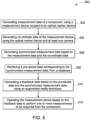
- FIG. 5 is a flow chart of a method 500 of inspection of a component in accordance with another exemplary embodiment.
- the method 500 includes generating measurement data of a component, using a measurement device coupled to an optical marker device as indicated in step 502.
- the optical marker device includes a plurality of optical markers arranged in a predefined three-dimensional configuration.
- the step of generating measurement data includes initial calibration of an optical tracking system and initialization with predefined measurement data.
- the calibration of the optical tracking system includes positioning the component at a convenient position and then positioning the measurement device at an initial measurement location. The calibration of the optical tracking system is concluded after recording of the initial measurement. Subsequently, for other measurement locations, calibration and initialization steps are not required.
- the generation of measurement data may be performed by selecting measurement locations in any order.
- the method 500 includes generating co-ordinate data of the measurement device, using the optical marker device and at least one camera.
- the co-ordinate data includes position data and orientation data.
- the co-ordinate data is generated by acquiring one or more images of the optical marker device, using the at least one camera. Further a position and an orientation of the optical marker device are determined in real time, using a computer vision technique.
- the step of generating co-ordinate data includes obtaining three dimensional co-ordinates of a plurality of optical markers of the optical marker device, arranged in a predefined three-dimensional configuration.
- the method 500 includes generating synchronized measurement data based on the measurement data and the orientation data.
- the method of generating the synchronized measurement data includes modifying the measurement data based on the orientation data.
- the method includes retrieving pre-stored data corresponding to the synchronized measurement data, from a database.
- the pre-stored data includes predefined measurement data and a plurality of tolerance values corresponding to the predefined measurement data.
- the method 500 includes generating feedback data based on the pre-stored data and the synchronized measurement data, using an augmented reality technique.
- the feedback data may be representative of a plurality of measurement locations annotated to display progress of inspection. For example, one set of measurement locations may be represented as green dots to indicate completion of measurements and another set of measurement locations may be represented as red dots to indicate pending measurements.
- the step of generating the feedback data includes verifying measurement data with the predefined measurement data.
- the verifying step further includes identifying one or more measurements to be acquired by the measurement device.
- generating the feedback data includes generating at least one of graphical and audio information representative of the feedback data.
- the step of generating the feedback data includes overlaying a live image of a region of inspection of the component with the one or more measurements to be acquired.
- the method includes operating the measurement device based on the feedback data to perform one or more measurements to be acquired from the component.
- the operating of the measurement device may be performed manually by an operator or automatically by a robot device.
- the operation of the measurement device includes repeating the step 502 at a new measurement location.
- the operating the measurement device may further include automatic generation of inspection reports.
- one of the inspection reports may be a record of measurement data for reviewing purposes. Further, one of the inspection reports may be quality check report generated based on the measurement data. In one embodiment, the inspection reports may be stored in a repository or made available to quality management purposes. In another embodiment, the inspection reports may be processed further without manual intervention to initiate further actions by one or more of research, design, manufacturing and quality departments.
- the embodiments discussed herein employ an optical tracking system to obtain position and orientation of a measurement device in relation to a component and an augmented reality image representative of progress of a quality inspection process is generated.
- the quality inspection of complex shaped components requiring hundreds of measurements may be performed in relatively shorter time. As a result, an error free recording of measurement data is ensured. Measurements of the component may be obtained in any order. An operator is not burdened with a tedious task of maintaining a record of measurement locations where measurements are to be acquired during the progress of quality inspection of the component.
Landscapes
- Engineering & Computer Science (AREA)
- Physics & Mathematics (AREA)
- General Physics & Mathematics (AREA)
- Electromagnetism (AREA)
- Remote Sensing (AREA)
- Radar, Positioning & Navigation (AREA)
- Theoretical Computer Science (AREA)
- General Engineering & Computer Science (AREA)
- Computer Hardware Design (AREA)
- Computer Networks & Wireless Communication (AREA)
- Geometry (AREA)
- Evolutionary Computation (AREA)
- Computer Vision & Pattern Recognition (AREA)
- Quality & Reliability (AREA)
- Mechanical Engineering (AREA)
- Robotics (AREA)
- Multimedia (AREA)
- Software Systems (AREA)
- Automation & Control Theory (AREA)
- Computer Graphics (AREA)
- Computational Mathematics (AREA)
- Mathematical Analysis (AREA)
- Mathematical Optimization (AREA)
- Pure & Applied Mathematics (AREA)
- Length Measuring Devices By Optical Means (AREA)
Claims (12)
- Verfahren, umfassend:Erzeugen (502) von Messdaten einer Komponente unter Verwendung einer Messvorrichtung (102), die mit einer optischen Markervorrichtung (104) gekoppelt ist;Erzeugen (504) von Koordinatendaten der Messvorrichtung (102) unter Verwendung der optischen Markervorrichtung (104) und mindestens einer Kamera (110);Erzeugen (506) synchronisierter Messdaten durch Modifizieren der Messdaten basierend auf den Koordinatendaten;Abrufen (508) zuvor gespeicherter Daten, die den synchronisierten Messdaten entsprechen, von einer Datenbank (120);Erzeugen (510) von Rückkopplungsdaten basierend auf den zuvor gespeicherten Daten und den synchronisierten Messdaten unter Verwendung einer Augmented-Reality-Technik; undBetreiben (512) der Messvorrichtung (102) basierend auf den Rückkopplungsdaten, um eine oder mehrere Messungen durchzuführen, die von der Komponente erfasst werden sollen;wobei das Erzeugen der Koordinatendaten der Messvorrichtung (102) umfasst:Erfassen eines oder mehrerer Bilder der optischen Markervorrichtung (104) unter Verwendung der mindestens einen Kamera (110);und Bestimmen einer Position und einer Ausrichtung der optischen Markervorrichtung (104) in Echtzeit unter Verwendung einer Computervisionstechnik; unddadurch gekennzeichnet, dass die Messdaten unter Verwendung eines digitalen Tasters als die Messvorrichtung (102) erzeugt werden und einen oder mehrere von einem Längenwert, einem Breitenwert, einem Höhenwert und einem Radiuswert der Komponente einschließen.
- Verfahren nach Anspruch 1, ferner umfassend das Betreiben der Messvorrichtung (102) unter Verwendung einer Robotervorrichtung (148).
- Verfahren nach Anspruch 1 oder 2, wobei das Erzeugen der Koordinatendaten ein Erhalten dreidimensionaler Koordinaten einer Vielzahl von optischen Markern der optischen Markervorrichtung (104) umfasst, die in einer zuvor definierten dreidimensionalen Konfiguration angeordnet sind.
- Verfahren nach einem der vorstehenden Ansprüche, wobei die zuvor gespeicherten Daten zuvor definierte Messdaten und eine Vielzahl von Toleranzwerten umfassen, die den vordefinierten Messdaten entsprechen.
- Verfahren nach einem der vorstehenden Ansprüche, wobei das Erzeugen der Rückkopplungsdaten ein Verifizieren einer Erfassung einer oder mehrerer Messungen der zuvor definierten Messdaten umfasst.
- Verfahren nach einem der vorstehenden Ansprüche, wobei das Verifizieren der Erfassung der zuvor definierten Messdaten ein Identifizieren der einen oder der mehreren Messungen umfasst, die durch die Messvorrichtung erfasst werden sollen.
- Verfahren nach einem der vorstehenden Ansprüche, wobei das Erzeugen der Rückkopplungsdaten das Erzeugen mindestens eines von grafischen und Audioinformationen umfasst, die für die Rückkopplungsdaten repräsentativ sind.
- Verfahren nach einem der vorstehenden Ansprüche, wobei das Erzeugen der Rückkopplungsdaten ein Überlagern eines Live-Bildes eines Prüfbereichs der Komponente mit der einen oder den mehreren Messungen umfasst, die erfasst werden sollen.
- System (100), umfassend:eine Messvorrichtung (102), die mit einer optischen Markervorrichtung (104) des Systems gekoppelt werden soll und konfiguriert ist, um Messdaten einer Komponente zu erzeugen;mindestens eine Kamera (110), die konfiguriert ist, um die optische Markervorrichtung (104) zu überwachen und Koordinatendaten der Messvorrichtung (102) zu erzeugen;eine Messsteuereinheit (114), die mit der Messvorrichtung (102) und der mindestens einen Kamera (110) kommunikativ gekoppelt und konfiguriert ist zum:Empfangen der Messdaten von der Messvorrichtung (102);Empfangen der Koordinatendaten von der mindestens einen Kamera (110);Modifizieren der Messdaten basierend auf den Koordinatendaten, um synchronisierte Messdaten zu erzeugen;Abrufen zuvor gespeicherter Daten, die den synchronisierten Messdaten entsprechen, von einer Datenbank (120) des Systems;Erzeugen von Rückkopplungsdaten basierend auf den zuvor gespeicherten Daten und den synchronisierten Messdaten unter Verwendung einer Augmented-Reality-Technik; undErzeugen eines Steuersignals (144) zum Betreiben der Messvorrichtung (102) basierend auf den Rückkopplungsdaten, um eine oder mehrere Messungen durchzuführen, die von der Komponente erfasst werden sollen;wobei die mindestens eine Kamera (110) konfiguriert ist zum:Erfassen eines oder mehrerer Bilder der optischen Markervorrichtung (104); undBestimmen einer Position und einer Ausrichtung der optischen Markervorrichtung (104) in Echtzeit unter Verwendung einer Computervisionstechnik; undwobei die Messdaten einen oder mehrere von einem Längenwert, einem Breitenwert, einem Höhenwert und einem Radiuswert der Komponente einschließen;dadurch gekennzeichnet, dass die Messvorrichtung (102) ein digitaler Taster ist.
- System nach Anspruch 9, ferner umfassend eine Robotervorrichtung (148), die konfiguriert ist, um die Messvorrichtung (102) zu betreiben.
- System nach Anspruch 9 oder 10, wobei die optische Markervorrichtung (104) eine Vielzahl von optischen Markern umfasst, die in einer zuvor definierten dreidimensionalen Konfiguration angeordnet sind.
- Nichtflüchtiges computerlesbares Medium, das Anweisungen aufweist, um mindestens ein Prozessormodul zu aktivieren, um ein Verfahren durchzuführen, umfassend:Erzeugen von Messdaten einer Komponente unter Verwendung einer Messvorrichtung (102), die mit einer optischen Markervorrichtung (104) gekoppelt ist;Erzeugen von Koordinatendaten der Messvorrichtung (102) unter Verwendung der optischen Markervorrichtung (104) und mindestens einer Kamera (110);Erzeugen synchronisierter Messdaten durch Modifizieren der Messdaten basierend auf den Koordinatendaten;Abrufen zuvor gespeicherter Daten, die den synchronisierten Messdaten entsprechen, von einer Datenbank (120);Erzeugen von Rückkopplungsdaten basierend auf den zuvor gespeicherten Daten und den synchronisierten Messdaten unter Verwendung einer Augmented-Reality-Technik; undErzeugen eines Steuersignals (144) zum Betreiben der Messvorrichtung (102) basierend auf den Rückkopplungsdaten, um eine oder mehrere Messungen durchzuführen, die von der Komponente erfasst werden sollen;wobei das Erzeugen der Koordinatendaten der Messvorrichtung (102) umfasst:Erfassen eines oder mehrerer Bilder der optischen Markervorrichtung (104) unter Verwendung der mindestens einen Kamera (110);und Bestimmen einer Position und einer Ausrichtung der optischen Markervorrichtung (104) in Echtzeit unter Verwendung einer Computervisionstechnik; unddadurch gekennzeichnet, dass die Messdaten unter Verwendung eines digitalen Tasters als die Messvorrichtung (102) erzeugt werden und einen oder mehrere von einem Längenwert, einem Breitenwert, einem Höhenwert und einem Radiuswert der Komponente einschließen.
Applications Claiming Priority (1)
| Application Number | Priority Date | Filing Date | Title |
|---|---|---|---|
| US15/292,634 US20180108178A1 (en) | 2016-10-13 | 2016-10-13 | System and method for measurement based quality inspection |
Publications (2)
| Publication Number | Publication Date |
|---|---|
| EP3309504A1 EP3309504A1 (de) | 2018-04-18 |
| EP3309504B1 true EP3309504B1 (de) | 2023-08-23 |
Family
ID=60043107
Family Applications (1)
| Application Number | Title | Priority Date | Filing Date |
|---|---|---|---|
| EP17195508.1A Active EP3309504B1 (de) | 2016-10-13 | 2017-10-09 | System und verfahren zur qualitätsprüfung aufgrund einer messungen |
Country Status (3)
| Country | Link |
|---|---|
| US (1) | US20180108178A1 (de) |
| EP (1) | EP3309504B1 (de) |
| CN (1) | CN107941145A (de) |
Families Citing this family (22)
| Publication number | Priority date | Publication date | Assignee | Title |
|---|---|---|---|---|
| FR3022065B1 (fr) * | 2014-06-04 | 2017-10-13 | European Aeronautic Defence & Space Co Eads France | Procede de generation d'une maquette numerique enrichie |
| US10962512B2 (en) | 2015-08-03 | 2021-03-30 | Safetraces, Inc. | Pathogen surrogates based on encapsulated tagged DNA for verification of sanitation and wash water systems for fresh produce |
| JP7061119B2 (ja) | 2016-07-15 | 2022-04-27 | ファストブリック・アイピー・プロプライエタリー・リミテッド | 車両に組み込まれた煉瓦/ブロック敷設機 |
| ES2899585T3 (es) | 2016-07-15 | 2022-03-14 | Fastbrick Ip Pty Ltd | Pluma para transporte de material |
| CN111095355B (zh) | 2017-07-05 | 2023-10-20 | 快砖知识产权私人有限公司 | 实时定位和定向跟踪器 |
| AU2018317941B2 (en) | 2017-08-17 | 2023-11-09 | Fastbrick Ip Pty Ltd | Laser tracker with improved roll angle measurement |
| US11958193B2 (en) | 2017-08-17 | 2024-04-16 | Fastbrick Ip Pty Ltd | Communication system for an interaction system |
| CN111212799B (zh) | 2017-10-11 | 2023-04-14 | 快砖知识产权私人有限公司 | 用于传送物体的机器以及与其一起使用的多隔间转盘 |
| US10926264B2 (en) | 2018-01-10 | 2021-02-23 | Safetraces, Inc. | Dispensing system for applying DNA taggants used in combinations to tag articles |
| US10556032B2 (en) | 2018-04-25 | 2020-02-11 | Safetraces, Inc. | Sanitation monitoring system using pathogen surrogates and surrogate tracking |
| US12311546B2 (en) | 2018-07-16 | 2025-05-27 | Fastbrick Ip Pty Ltd | Active damping system |
| WO2020014737A1 (en) | 2018-07-16 | 2020-01-23 | Fastbrick Ip Pty Ltd | Backup tracking for an interaction system |
| US11853832B2 (en) | 2018-08-28 | 2023-12-26 | Safetraces, Inc. | Product tracking and rating system using DNA tags |
| EP3783458B1 (de) * | 2019-08-22 | 2023-04-05 | Innovmetric Logiciels Inc. | Verfahren und systeme zur erzeugung von rückführbaren messungen |
| US11209261B2 (en) | 2019-08-22 | 2021-12-28 | Innovmetric Logiciels Inc. | Methods and systems for producing traceable measurements |
| US12258638B2 (en) | 2020-04-16 | 2025-03-25 | Safetraces, Inc. | Airborne pathogen simulants and mobility testing |
| CN115443363A (zh) | 2020-04-22 | 2022-12-06 | 快砖知识产权私人有限公司 | 块传送装置及用于与其一起使用的改进的夹紧组件 |
| US11614319B2 (en) * | 2020-06-26 | 2023-03-28 | Faro Technologies, Inc. | User interface for three-dimensional measurement device |
| AU2021304545B2 (en) | 2020-07-08 | 2025-12-04 | Fastbrick Ip Pty Ltd | Adhesive application system |
| CN112734588B (zh) * | 2021-01-05 | 2024-12-10 | 新代科技(苏州)有限公司 | 扩增实境加工辅助系统及其使用方法 |
| US12210330B2 (en) * | 2022-05-27 | 2025-01-28 | Caterpillar Inc. | Systems and methods for determining thickness and/or diameter using computer vision |
| CN120522725A (zh) * | 2025-04-10 | 2025-08-22 | 银河航天科技(南通)有限公司 | 卫星组件的检验方法、装置、电子设备及存储介质 |
Family Cites Families (10)
| Publication number | Priority date | Publication date | Assignee | Title |
|---|---|---|---|---|
| CN1300551C (zh) * | 2002-07-25 | 2007-02-14 | 索卢申力士公司 | 使用光学标记自动排列三维扫描数据的设备和方法 |
| US7945311B2 (en) * | 2006-02-09 | 2011-05-17 | Northern Digital Inc. | Retroreflective marker-tracking systems |
| US9245062B2 (en) * | 2012-03-22 | 2016-01-26 | Virtek Vision International Inc. | Laser projection system using variable part alignment |
| DE102012212754B4 (de) * | 2012-06-29 | 2022-03-03 | Robert Bosch Gmbh | Verfahren zum Betreiben eines Sensorsystems sowie Sensorsystem |
| DE202012007557U1 (de) * | 2012-08-09 | 2013-11-11 | MBQ Qualitätssicherungs-GmbH | Messsystem zur Materialdickenmessung |
| EP2698596A1 (de) * | 2012-08-16 | 2014-02-19 | Hexagon Technology Center GmbH | Verfahren und System zur Bestimmung der räumlichen Koordinaten mit einer mobilen Koordinatenmessmaschine |
| US9594250B2 (en) * | 2013-12-18 | 2017-03-14 | Hexagon Metrology, Inc. | Ultra-portable coordinate measurement machine |
| JP6316663B2 (ja) * | 2014-05-30 | 2018-04-25 | 株式会社キーエンス | 座標測定装置 |
| DE102014013724A1 (de) * | 2014-09-22 | 2016-03-24 | Andreas Enders | Verfahren zum Abstecken von Bohrlöchern eines Fahrzeugs |
| DE102016105496A1 (de) * | 2015-03-26 | 2016-09-29 | Faro Technologies Inc. | System zur Prüfung von Objekten mittels erweiterter Realität |
-
2016
- 2016-10-13 US US15/292,634 patent/US20180108178A1/en not_active Abandoned
-
2017
- 2017-10-09 EP EP17195508.1A patent/EP3309504B1/de active Active
- 2017-10-13 CN CN201710957952.6A patent/CN107941145A/zh active Pending
Also Published As
| Publication number | Publication date |
|---|---|
| US20180108178A1 (en) | 2018-04-19 |
| CN107941145A (zh) | 2018-04-20 |
| EP3309504A1 (de) | 2018-04-18 |
Similar Documents
| Publication | Publication Date | Title |
|---|---|---|
| EP3309504B1 (de) | System und verfahren zur qualitätsprüfung aufgrund einer messungen | |
| JP5429872B2 (ja) | 加工対象物を溶接するロボットを制御する方法および装置 | |
| JP6789411B2 (ja) | 機械視覚システム | |
| JP2015057612A (ja) | 非接触測定を行う装置および方法 | |
| CN106536128A (zh) | 用于基于图像地定位工件加工过程的方法、加工机和计算机程序产品 | |
| CN109313333B (zh) | 用于接合视觉检视装置的方法和系统 | |
| EP3322959B1 (de) | Verfahren zum messen eines artefakts | |
| KR102706337B1 (ko) | 컴퓨터로 생성된 가상 기준 물체를 구비한 머신 비전 시스템 | |
| EP3491333B1 (de) | Kontaktlose sonde und verfahren zum betrieb | |
| JP2024039635A (ja) | ツール又はコンプリートツールを測定するためのデバイス、及び、ツール又はコンプリートツールのデジタル画像をコンパイルするための方法 | |
| JPWO2018225159A1 (ja) | 情報処理装置および加工不良特定方法 | |
| JP6561089B2 (ja) | 厚み測定装置、および厚み測定プログラム | |
| EP3563273B1 (de) | Formen von zusammengesetzten lagen auf einem verbundteillaminierungswerkzeug mit hilfe von erweiterten realität | |
| CN107764182A (zh) | 测量系统以及用于配置测量系统的方法 | |
| CN117644294B (zh) | 一种基于视觉预览引导的激光加工方法及控制装置 | |
| CN113272868B (zh) | 将基于数字模型计算的图像投影至工件上的方法、模块和系统 | |
| Schöch et al. | Enhancing multisensor data fusion on light sectioning coordinate measuring systems for the in-process inspection of freeform shaped parts | |
| KR102197729B1 (ko) | 산업기계설비 진단 및 위치제어시스템 | |
| CN114170314B (zh) | 一种基于智能3d视觉处理3d眼镜工艺轨迹执行方法 | |
| Bengtsson | Hardware Design and Evaluation of Non-planar Fused Deposition Modeling on a 3-axis printer | |
| JP2024072429A (ja) | 画像処理装置、画像処理方法、ロボットシステム、物品の製造方法、撮像装置、撮像装置の制御方法、プログラム及び記録媒体 | |
| WO2025027861A1 (ja) | 計測システム | |
| US20190171015A1 (en) | System and method for recording and representing measurement points on a body surface | |
| CN119665839A (zh) | 对象高度差测量方法、装置及电子设备 | |
| JP2005091374A (ja) | 変位センサ及び変位計測方法 |
Legal Events
| Date | Code | Title | Description |
|---|---|---|---|
| PUAI | Public reference made under article 153(3) epc to a published international application that has entered the european phase |
Free format text: ORIGINAL CODE: 0009012 |
|
| STAA | Information on the status of an ep patent application or granted ep patent |
Free format text: STATUS: THE APPLICATION HAS BEEN PUBLISHED |
|
| AK | Designated contracting states |
Kind code of ref document: A1 Designated state(s): AL AT BE BG CH CY CZ DE DK EE ES FI FR GB GR HR HU IE IS IT LI LT LU LV MC MK MT NL NO PL PT RO RS SE SI SK SM TR |
|
| AX | Request for extension of the european patent |
Extension state: BA ME |
|
| STAA | Information on the status of an ep patent application or granted ep patent |
Free format text: STATUS: REQUEST FOR EXAMINATION WAS MADE |
|
| 17P | Request for examination filed |
Effective date: 20181018 |
|
| RBV | Designated contracting states (corrected) |
Designated state(s): AL AT BE BG CH CY CZ DE DK EE ES FI FR GB GR HR HU IE IS IT LI LT LU LV MC MK MT NL NO PL PT RO RS SE SI SK SM TR |
|
| STAA | Information on the status of an ep patent application or granted ep patent |
Free format text: STATUS: EXAMINATION IS IN PROGRESS |
|
| 17Q | First examination report despatched |
Effective date: 20200430 |
|
| GRAP | Despatch of communication of intention to grant a patent |
Free format text: ORIGINAL CODE: EPIDOSNIGR1 |
|
| STAA | Information on the status of an ep patent application or granted ep patent |
Free format text: STATUS: GRANT OF PATENT IS INTENDED |
|
| RIC1 | Information provided on ipc code assigned before grant |
Ipc: G06F 30/00 20200101ALI20230405BHEP Ipc: G06T 7/00 20170101ALI20230405BHEP Ipc: G01S 5/16 20060101ALI20230405BHEP Ipc: G01C 15/00 20060101ALI20230405BHEP Ipc: B25J 19/02 20060101ALI20230405BHEP Ipc: G01S 17/66 20060101ALI20230405BHEP Ipc: G01S 17/06 20060101ALI20230405BHEP Ipc: G01C 11/00 20060101ALI20230405BHEP Ipc: G01B 21/04 20060101ALI20230405BHEP Ipc: G01B 11/00 20060101AFI20230405BHEP |
|
| INTG | Intention to grant announced |
Effective date: 20230504 |
|
| P01 | Opt-out of the competence of the unified patent court (upc) registered |
Effective date: 20230526 |
|
| GRAS | Grant fee paid |
Free format text: ORIGINAL CODE: EPIDOSNIGR3 |
|
| GRAA | (expected) grant |
Free format text: ORIGINAL CODE: 0009210 |
|
| STAA | Information on the status of an ep patent application or granted ep patent |
Free format text: STATUS: THE PATENT HAS BEEN GRANTED |
|
| AK | Designated contracting states |
Kind code of ref document: B1 Designated state(s): AL AT BE BG CH CY CZ DE DK EE ES FI FR GB GR HR HU IE IS IT LI LT LU LV MC MK MT NL NO PL PT RO RS SE SI SK SM TR |
|
| REG | Reference to a national code |
Ref country code: GB Ref legal event code: FG4D |
|
| REG | Reference to a national code |
Ref country code: CH Ref legal event code: EP |
|
| REG | Reference to a national code |
Ref country code: DE Ref legal event code: R096 Ref document number: 602017073020 Country of ref document: DE |
|
| REG | Reference to a national code |
Ref country code: IE Ref legal event code: FG4D |
|
| REG | Reference to a national code |
Ref country code: SE Ref legal event code: TRGR |
|
| REG | Reference to a national code |
Ref country code: NO Ref legal event code: T2 Effective date: 20230823 |
|
| REG | Reference to a national code |
Ref country code: LT Ref legal event code: MG9D |
|
| REG | Reference to a national code |
Ref country code: NL Ref legal event code: MP Effective date: 20230823 |
|
| REG | Reference to a national code |
Ref country code: AT Ref legal event code: MK05 Ref document number: 1603096 Country of ref document: AT Kind code of ref document: T Effective date: 20230823 |
|
| PG25 | Lapsed in a contracting state [announced via postgrant information from national office to epo] |
Ref country code: GR Free format text: LAPSE BECAUSE OF FAILURE TO SUBMIT A TRANSLATION OF THE DESCRIPTION OR TO PAY THE FEE WITHIN THE PRESCRIBED TIME-LIMIT Effective date: 20231124 |
|
| PG25 | Lapsed in a contracting state [announced via postgrant information from national office to epo] |
Ref country code: IS Free format text: LAPSE BECAUSE OF FAILURE TO SUBMIT A TRANSLATION OF THE DESCRIPTION OR TO PAY THE FEE WITHIN THE PRESCRIBED TIME-LIMIT Effective date: 20231223 |
|
| PG25 | Lapsed in a contracting state [announced via postgrant information from national office to epo] |
Ref country code: RS Free format text: LAPSE BECAUSE OF FAILURE TO SUBMIT A TRANSLATION OF THE DESCRIPTION OR TO PAY THE FEE WITHIN THE PRESCRIBED TIME-LIMIT Effective date: 20230823 Ref country code: PT Free format text: LAPSE BECAUSE OF FAILURE TO SUBMIT A TRANSLATION OF THE DESCRIPTION OR TO PAY THE FEE WITHIN THE PRESCRIBED TIME-LIMIT Effective date: 20231226 Ref country code: NL Free format text: LAPSE BECAUSE OF FAILURE TO SUBMIT A TRANSLATION OF THE DESCRIPTION OR TO PAY THE FEE WITHIN THE PRESCRIBED TIME-LIMIT Effective date: 20230823 Ref country code: LV Free format text: LAPSE BECAUSE OF FAILURE TO SUBMIT A TRANSLATION OF THE DESCRIPTION OR TO PAY THE FEE WITHIN THE PRESCRIBED TIME-LIMIT Effective date: 20230823 Ref country code: LT Free format text: LAPSE BECAUSE OF FAILURE TO SUBMIT A TRANSLATION OF THE DESCRIPTION OR TO PAY THE FEE WITHIN THE PRESCRIBED TIME-LIMIT Effective date: 20230823 Ref country code: IS Free format text: LAPSE BECAUSE OF FAILURE TO SUBMIT A TRANSLATION OF THE DESCRIPTION OR TO PAY THE FEE WITHIN THE PRESCRIBED TIME-LIMIT Effective date: 20231223 Ref country code: HR Free format text: LAPSE BECAUSE OF FAILURE TO SUBMIT A TRANSLATION OF THE DESCRIPTION OR TO PAY THE FEE WITHIN THE PRESCRIBED TIME-LIMIT Effective date: 20230823 Ref country code: GR Free format text: LAPSE BECAUSE OF FAILURE TO SUBMIT A TRANSLATION OF THE DESCRIPTION OR TO PAY THE FEE WITHIN THE PRESCRIBED TIME-LIMIT Effective date: 20231124 Ref country code: FI Free format text: LAPSE BECAUSE OF FAILURE TO SUBMIT A TRANSLATION OF THE DESCRIPTION OR TO PAY THE FEE WITHIN THE PRESCRIBED TIME-LIMIT Effective date: 20230823 Ref country code: AT Free format text: LAPSE BECAUSE OF FAILURE TO SUBMIT A TRANSLATION OF THE DESCRIPTION OR TO PAY THE FEE WITHIN THE PRESCRIBED TIME-LIMIT Effective date: 20230823 |
|
| PG25 | Lapsed in a contracting state [announced via postgrant information from national office to epo] |
Ref country code: PL Free format text: LAPSE BECAUSE OF FAILURE TO SUBMIT A TRANSLATION OF THE DESCRIPTION OR TO PAY THE FEE WITHIN THE PRESCRIBED TIME-LIMIT Effective date: 20230823 |
|
| PG25 | Lapsed in a contracting state [announced via postgrant information from national office to epo] |
Ref country code: ES Free format text: LAPSE BECAUSE OF FAILURE TO SUBMIT A TRANSLATION OF THE DESCRIPTION OR TO PAY THE FEE WITHIN THE PRESCRIBED TIME-LIMIT Effective date: 20230823 |
|
| PG25 | Lapsed in a contracting state [announced via postgrant information from national office to epo] |
Ref country code: SM Free format text: LAPSE BECAUSE OF FAILURE TO SUBMIT A TRANSLATION OF THE DESCRIPTION OR TO PAY THE FEE WITHIN THE PRESCRIBED TIME-LIMIT Effective date: 20230823 Ref country code: RO Free format text: LAPSE BECAUSE OF FAILURE TO SUBMIT A TRANSLATION OF THE DESCRIPTION OR TO PAY THE FEE WITHIN THE PRESCRIBED TIME-LIMIT Effective date: 20230823 Ref country code: ES Free format text: LAPSE BECAUSE OF FAILURE TO SUBMIT A TRANSLATION OF THE DESCRIPTION OR TO PAY THE FEE WITHIN THE PRESCRIBED TIME-LIMIT Effective date: 20230823 Ref country code: EE Free format text: LAPSE BECAUSE OF FAILURE TO SUBMIT A TRANSLATION OF THE DESCRIPTION OR TO PAY THE FEE WITHIN THE PRESCRIBED TIME-LIMIT Effective date: 20230823 Ref country code: DK Free format text: LAPSE BECAUSE OF FAILURE TO SUBMIT A TRANSLATION OF THE DESCRIPTION OR TO PAY THE FEE WITHIN THE PRESCRIBED TIME-LIMIT Effective date: 20230823 Ref country code: CZ Free format text: LAPSE BECAUSE OF FAILURE TO SUBMIT A TRANSLATION OF THE DESCRIPTION OR TO PAY THE FEE WITHIN THE PRESCRIBED TIME-LIMIT Effective date: 20230823 Ref country code: SK Free format text: LAPSE BECAUSE OF FAILURE TO SUBMIT A TRANSLATION OF THE DESCRIPTION OR TO PAY THE FEE WITHIN THE PRESCRIBED TIME-LIMIT Effective date: 20230823 |
|
| REG | Reference to a national code |
Ref country code: DE Ref legal event code: R097 Ref document number: 602017073020 Country of ref document: DE |
|
| PG25 | Lapsed in a contracting state [announced via postgrant information from national office to epo] |
Ref country code: IT Free format text: LAPSE BECAUSE OF FAILURE TO SUBMIT A TRANSLATION OF THE DESCRIPTION OR TO PAY THE FEE WITHIN THE PRESCRIBED TIME-LIMIT Effective date: 20230823 Ref country code: MC Free format text: LAPSE BECAUSE OF FAILURE TO SUBMIT A TRANSLATION OF THE DESCRIPTION OR TO PAY THE FEE WITHIN THE PRESCRIBED TIME-LIMIT Effective date: 20230823 |
|
| REG | Reference to a national code |
Ref country code: BE Ref legal event code: MM Effective date: 20231031 |
|
| PG25 | Lapsed in a contracting state [announced via postgrant information from national office to epo] |
Ref country code: LU Free format text: LAPSE BECAUSE OF NON-PAYMENT OF DUE FEES Effective date: 20231009 |
|
| PLBE | No opposition filed within time limit |
Free format text: ORIGINAL CODE: 0009261 |
|
| STAA | Information on the status of an ep patent application or granted ep patent |
Free format text: STATUS: NO OPPOSITION FILED WITHIN TIME LIMIT |
|
| PG25 | Lapsed in a contracting state [announced via postgrant information from national office to epo] |
Ref country code: LU Free format text: LAPSE BECAUSE OF NON-PAYMENT OF DUE FEES Effective date: 20231009 |
|
| 26N | No opposition filed |
Effective date: 20240524 |
|
| PG25 | Lapsed in a contracting state [announced via postgrant information from national office to epo] |
Ref country code: FR Free format text: LAPSE BECAUSE OF NON-PAYMENT OF DUE FEES Effective date: 20231023 Ref country code: SI Free format text: LAPSE BECAUSE OF FAILURE TO SUBMIT A TRANSLATION OF THE DESCRIPTION OR TO PAY THE FEE WITHIN THE PRESCRIBED TIME-LIMIT Effective date: 20230823 |
|
| PG25 | Lapsed in a contracting state [announced via postgrant information from national office to epo] |
Ref country code: BE Free format text: LAPSE BECAUSE OF NON-PAYMENT OF DUE FEES Effective date: 20231031 |
|
| PG25 | Lapsed in a contracting state [announced via postgrant information from national office to epo] |
Ref country code: IE Free format text: LAPSE BECAUSE OF NON-PAYMENT OF DUE FEES Effective date: 20231009 |
|
| PG25 | Lapsed in a contracting state [announced via postgrant information from national office to epo] |
Ref country code: IE Free format text: LAPSE BECAUSE OF NON-PAYMENT OF DUE FEES Effective date: 20231009 |
|
| PG25 | Lapsed in a contracting state [announced via postgrant information from national office to epo] |
Ref country code: BG Free format text: LAPSE BECAUSE OF FAILURE TO SUBMIT A TRANSLATION OF THE DESCRIPTION OR TO PAY THE FEE WITHIN THE PRESCRIBED TIME-LIMIT Effective date: 20230823 |
|
| PG25 | Lapsed in a contracting state [announced via postgrant information from national office to epo] |
Ref country code: BG Free format text: LAPSE BECAUSE OF FAILURE TO SUBMIT A TRANSLATION OF THE DESCRIPTION OR TO PAY THE FEE WITHIN THE PRESCRIBED TIME-LIMIT Effective date: 20230823 |
|
| PG25 | Lapsed in a contracting state [announced via postgrant information from national office to epo] |
Ref country code: CY Free format text: LAPSE BECAUSE OF FAILURE TO SUBMIT A TRANSLATION OF THE DESCRIPTION OR TO PAY THE FEE WITHIN THE PRESCRIBED TIME-LIMIT; INVALID AB INITIO Effective date: 20171009 |
|
| PG25 | Lapsed in a contracting state [announced via postgrant information from national office to epo] |
Ref country code: HU Free format text: LAPSE BECAUSE OF FAILURE TO SUBMIT A TRANSLATION OF THE DESCRIPTION OR TO PAY THE FEE WITHIN THE PRESCRIBED TIME-LIMIT; INVALID AB INITIO Effective date: 20171009 |
|
| PGFP | Annual fee paid to national office [announced via postgrant information from national office to epo] |
Ref country code: NO Payment date: 20250925 Year of fee payment: 9 |
|
| PGFP | Annual fee paid to national office [announced via postgrant information from national office to epo] |
Ref country code: GB Payment date: 20250923 Year of fee payment: 9 |
|
| PGFP | Annual fee paid to national office [announced via postgrant information from national office to epo] |
Ref country code: SE Payment date: 20250923 Year of fee payment: 9 |
|
| REG | Reference to a national code |
Ref country code: CH Ref legal event code: U11 Free format text: ST27 STATUS EVENT CODE: U-0-0-U10-U11 (AS PROVIDED BY THE NATIONAL OFFICE) Effective date: 20251101 |
|
| PG25 | Lapsed in a contracting state [announced via postgrant information from national office to epo] |
Ref country code: TR Free format text: LAPSE BECAUSE OF FAILURE TO SUBMIT A TRANSLATION OF THE DESCRIPTION OR TO PAY THE FEE WITHIN THE PRESCRIBED TIME-LIMIT Effective date: 20230823 |
|
| PGFP | Annual fee paid to national office [announced via postgrant information from national office to epo] |
Ref country code: DE Payment date: 20250923 Year of fee payment: 9 |
|
| PGFP | Annual fee paid to national office [announced via postgrant information from national office to epo] |
Ref country code: CH Payment date: 20251101 Year of fee payment: 9 |