EP3309450B1 - Vorrichtung zum beleuchten von zueinander winkelig angeordneten flächen - Google Patents
Vorrichtung zum beleuchten von zueinander winkelig angeordneten flächen Download PDFInfo
- Publication number
- EP3309450B1 EP3309450B1 EP17195402.7A EP17195402A EP3309450B1 EP 3309450 B1 EP3309450 B1 EP 3309450B1 EP 17195402 A EP17195402 A EP 17195402A EP 3309450 B1 EP3309450 B1 EP 3309450B1
- Authority
- EP
- European Patent Office
- Prior art keywords
- light component
- optical system
- deflecting optical
- floor
- lit
- Prior art date
- Legal status (The legal status is an assumption and is not a legal conclusion. Google has not performed a legal analysis and makes no representation as to the accuracy of the status listed.)
- Active
Links
Images

Classifications
-
- F—MECHANICAL ENGINEERING; LIGHTING; HEATING; WEAPONS; BLASTING
- F21—LIGHTING
- F21V—FUNCTIONAL FEATURES OR DETAILS OF LIGHTING DEVICES OR SYSTEMS THEREOF; STRUCTURAL COMBINATIONS OF LIGHTING DEVICES WITH OTHER ARTICLES, NOT OTHERWISE PROVIDED FOR
- F21V7/00—Reflectors for light sources
- F21V7/0008—Reflectors for light sources providing for indirect lighting
- F21V7/0016—Reflectors for light sources providing for indirect lighting on lighting devices that also provide for direct lighting, e.g. by means of independent light sources, by splitting of the light beam, by switching between both lighting modes
-
- F—MECHANICAL ENGINEERING; LIGHTING; HEATING; WEAPONS; BLASTING
- F21—LIGHTING
- F21V—FUNCTIONAL FEATURES OR DETAILS OF LIGHTING DEVICES OR SYSTEMS THEREOF; STRUCTURAL COMBINATIONS OF LIGHTING DEVICES WITH OTHER ARTICLES, NOT OTHERWISE PROVIDED FOR
- F21V7/00—Reflectors for light sources
- F21V7/04—Optical design
- F21V7/048—Optical design with facets structure
-
- F—MECHANICAL ENGINEERING; LIGHTING; HEATING; WEAPONS; BLASTING
- F21—LIGHTING
- F21V—FUNCTIONAL FEATURES OR DETAILS OF LIGHTING DEVICES OR SYSTEMS THEREOF; STRUCTURAL COMBINATIONS OF LIGHTING DEVICES WITH OTHER ARTICLES, NOT OTHERWISE PROVIDED FOR
- F21V7/00—Reflectors for light sources
- F21V7/04—Optical design
- F21V7/09—Optical design with a combination of different curvatures
-
- F—MECHANICAL ENGINEERING; LIGHTING; HEATING; WEAPONS; BLASTING
- F21—LIGHTING
- F21Y—INDEXING SCHEME ASSOCIATED WITH SUBCLASSES F21K, F21L, F21S and F21V, RELATING TO THE FORM OR THE KIND OF THE LIGHT SOURCES OR OF THE COLOUR OF THE LIGHT EMITTED
- F21Y2115/00—Light-generating elements of semiconductor light sources
- F21Y2115/10—Light-emitting diodes [LED]
Definitions
- the present invention relates to a device for illuminating two mutually angled surfaces, in particular wall and floor surfaces, with at least one emitter, which has at least one light source and deflecting optics comprising a reflector and / or a lens, the deflecting optics light emitted by the light source and emits it in the form of a bundle of rays onto both surfaces, so that a surface piece is illuminated on both surfaces, the bundle of rays comprising an indirect light component reflected by the deflecting optics and a direct light component unreflected by the deflecting optics, which partially superimpose one another.
- a wallwasher is known, the reflector of which has a rectangular cross-section and comprises a half-sided insert which causes a double reflection for part of the emitted light.
- This known wallwasher thus emits three separate light bundles: An unreflected direct light bundle is shone on the floor. A single reflected indirect light beam is reflected onto a lower portion of the wall and a third, doubly reflected indirect light beam is reflected onto an upper portion of the wall.
- spotlights can be used that use deflection optics to specifically direct the emitted light cone onto the floor or a wall in order to illuminate corresponding areas on the floor and / or the wall.
- spotlights that are mounted at the upper end of a wall adjacent to this, for example on the ceiling, and illuminate the wall are sometimes referred to as wallwashers.
- spotlights that generally radiate downwards onto a floor surface are sometimes referred to as downlights, with such Spotlights can be integrated, for example, in ceiling panels and combined in matrix-like spotlight arrangements.
- Such spotlight arrangements are not only popular for lighting rooms and halls, but can also be used as shop lighting, for example for lighting showcases, as shelf lighting, kitchen lighting, aisle lighting, staircase lighting or in conference rooms for blackboard or flipchart lighting.
- radiator arrangements can also be built into electrical devices such as refrigerators and ovens in order to illuminate the wall and / or floor surfaces of the devices.
- the present invention is based on the object of creating an improved lighting device of the type mentioned at the beginning which avoids the disadvantages of the prior art and further develops the latter in an advantageous manner.
- an improved radiator is to be created which can uniformly illuminate surfaces angled to one another without visible inhomogeneities.
- the deflecting optics of the radiator in such a way that the direct and indirect light components of the beam are not congruent and insofar as inhomogeneity in the illumination is permitted, the resulting light-dark edge between the area piece that is only illuminated by indirect light and the piece of surface which is also illuminated by direct light, however, is banished to the transition between the two angled surfaces and is made more or less invisible in this respect.
- the deflecting optics are designed to limit the unreflected direct light portion so that the said direct light portion falls on only one of the two angled surfaces and an edge of the surface piece irradiated by the direct light extends along the angled transition between the two surfaces.
- the typical brightness edge that changes at the transition from the surface area that is irradiated by both direct and indirect light to the surface area that is only irradiated by indirect light is not eliminated, but shifted to an area in which this brightness edge is not noticeable, and thus made almost invisible to the human eye. Because there is still a surface piece irradiated only by indirect light and a surface piece irradiated by both indirect light and direct light, the contours of the optically active surfaces of the deflecting optics remain manageable in order to achieve uniform light intensity distributions on the respective surface piece.
- the wall surface piece, which is irradiated in the manner of a wall washer can be uniformly illuminated and the strongly asymmetrical light distribution required for this can be achieved.
- Said deflection optics can achieve the limitation of the direct light component in the beam with a direct light edge running along the transition between the angled surfaces, both by a reflector and by a lens, with both a reflector and a lens possibly being provided.
- the deflecting optics uses a reflector that captures light emitted by the light source with at least one reflector surface and transforms it into a beam
- the reflector can, in a further development of the invention, comprise a tear-off edge delimiting the reflector surface, which delimits the unreflected portion of the direct light emitted and is contoured in such a way that the The said direct light component only falls on one of the two surfaces that are arranged at an angle to one another and the edge of the area piece illuminated by the direct light component runs along the transition between the two angled surfaces.
- the deflecting optics have a lens as an alternative or in addition to such a reflector
- the light captured by the lens can partially be totally reflected on a lateral surface of the lens by appropriate contouring of the lens or, if appropriate, also reflected, with a corresponding coating, while a direct light component passing centrally through the lens is emitted unreflected from the light exit surface of the lens.
- the direct light component means the light component passing through the lens that is not reflected or totally reflected on the lens surface, but goes directly from the light entry to the light exit area and is deflected there by refraction.
- the one for this direct light component responsible light entry and exit surfaces of the lens can be contoured in such a way that the mentioned direct light portion of the emitted beam is limited in the mentioned way to one of the surfaces, in particular the floor area, and the edge of the surface piece irradiated by the direct light extends along the mentioned angular transition area .
- the angled transition area between the two angled surfaces does not need to be a sharp edge in the sense of the mathematical line of intersection of two levels, but can also be rounded, as is the case, for example, with stucco moldings or baseboards designed in the shape of a concave to embellish the transition between ceiling and wall or wall and floor is known.
- the deflecting optics can advantageously be designed such that the surface piece irradiated by the direct light component is essentially completely irradiated by the indirect light component.
- the indirect light component can also be thrown onto the surface that is irradiated by the direct light component in such a way that the surface pieces irradiated by the direct light component and the indirect light component are congruent or at least approximately congruent with one another.
- the deflection optics can be designed in such a way that the reflected indirect light component falls on both one and the other of the two surfaces arranged at an angle to one another, with the indirect light component falling on one surface and the indirect light component falling on the other surface creating a homogeneous transition between the can have both surfaces and / or a uniform light intensity distribution across the border of the two surfaces.
- the surface pieces illuminated in each case on the two surfaces can in principle be contoured differently, for example a rectangular patch and a semicircular or triangular patch on the floor.
- the deflecting optics can be designed to illuminate a rectangular area piece both on the wall surface and on the floor surface.
- the contours of the deflecting optics delimiting the direct light component can be shaped in such a way that the area piece irradiated by the direct light has a rectangular outline contour.
- the reflective or totally reflective surfaces of the deflecting optics can be contoured in such a way that the indirect light portion of the beam also irradiates a rectangular area on the floor and the wall or on the two mutually angled surfaces.
- the spotlight can be arranged or mounted differently. If an upright wall surface and a lying floor surface are to be illuminated by the spotlight, the spotlight can be arranged at an upper end section of the wall at a distance from this, in particular be mounted flush with the ceiling and / or sunk into an adjacent ceiling and one down on the floor and / or the wall have to be directed main radiation direction, so that the wall surface is irradiated abrasively and the floor surface is irradiated approximately frontally.
- the deflecting optics can advantageously be designed in such a way that the surface piece lying on the wall surface, which is illuminated by the beam of the radiator, in particular its indirect light component, extends from the floor to essentially the height of the radiator. If the radiator is mounted flush with the ceiling in the above-mentioned manner or is arranged on the ceiling, the mentioned area piece can extend from the floor to the ceiling of the corresponding room.
- said reflector is subdivided into a plurality of reflector segments and / or designed with multiple shells. Different reflector segments illuminate different pieces of surface.
- the reflector surface segments are designed to illuminate different surface pieces, whereby it can be provided in particular that a first reflector surface segment illuminates the floor surface piece and a second reflector surface segment illuminates the wall surface piece and the transition of the surface pieces irradiated by the two reflector surface segments along the fold or the angled transition extends between the two surfaces.
- a first reflector surface segment illuminates the floor surface piece
- a second reflector surface segment illuminates the wall surface piece and the transition of the surface pieces irradiated by the two reflector surface segments along the fold or the angled transition extends between the two surfaces.
- the reflector surface segments can be determined in groups to irradiate the floor surface piece on the one hand and the wall surface piece on the other hand.
- two reflector surface segments jointly irradiate the wall surface piece to be illuminated, while two other reflector surface segments jointly illuminate the floor surface piece.
- each of the multiple reflector surface segments provided for illuminating the wall surface can illuminate 100% of the respective surface piece on one of the angled surfaces.
- the deflecting optics can be faceted and / or microstructured on their reflective or totally reflective surfaces be.
- microfacets can be provided, which can be designed in the form of flat flats, concave dents or convex pimples, with a plurality of such facets being provided on a light-technically active surface, for example more than 25 or more than 50 or more than 100 such facets in a multi-row and / or multi-column arrangement.
- other relief-like microstructures such as geometrically regular relief contours such as truncated pyramids, conical elevations or depressions or similar structures can also be provided.
- the aforementioned faceting and / or microstructuring can be provided on the reflector surfaces of the reflector.
- the deflecting optics are designed to be only simply reflective, so that the light captured by the deflecting optics is only reflected once before it is radiated onto the surface piece on the wall or on the floor.
- the lighting device can comprise a radiator 1, which has two surfaces arranged at an angle to one another, for example in Irradiated in the form of an upright wall 2 and a lying floor 3, the radiator 1 more precisely irradiating surface pieces 4 and 5 on said wall 2 and the floor 3 that adjoin each other and so to speak over the fold 6 or the angular transition between the wall 2 and floor 3 go away.
- a radiator 1 which has two surfaces arranged at an angle to one another, for example in Irradiated in the form of an upright wall 2 and a lying floor 3, the radiator 1 more precisely irradiating surface pieces 4 and 5 on said wall 2 and the floor 3 that adjoin each other and so to speak over the fold 6 or the angular transition between the wall 2 and floor 3 go away.
- the surface pieces 4 and 5 mentioned can each be of rectangular design, which is achieved by a corresponding design or contouring of the deflecting optics 7, which will be explained in more detail.
- the deflecting optics 7 comprises a reflector 8 that captures light emitted by a light source 10 and transforms it into a beam that illuminates both the wall 2 and the floor 3 or the surface pieces 4 and 5 lying on it.
- an LED can be provided as the light source 10, which can be provided on a printed circuit board 11 or another light source carrier, wherein said reflector 8 can sit on said printed circuit board 11 and surround the light source 10.
- the radiator 1 can also comprise more than one light source 10, for example a plurality of LEDs arranged next to one another, which can have different colors or the same color.
- the spotlight 1 can advantageously be arranged at a distance from the upper end area of the wall 2 to be illuminated, for example mounted on an adjoining ceiling, wherein the named spotlight 1 can be mounted flush with the ceiling and / or sunk into the named ceiling, as is the case with downlights, for example or wall washing is known per se.
- the radiator 1 has a main radiation direction directed downwards towards the floor 3 and / or the wall 2, wherein in particular the said reflector 8 can "look" downwards at the floor and / or the wall 2.
- the light source 1 and / or the circuit board 11 on which the light source 10 is arranged can advantageously be positioned inclined at an acute angle to the ceiling and / or at an acute angle to the surface of the floor 3, in particular in such a way that the height of the circuit board 11 with increasing distance from the wall 2 increases. In principle, an arrangement parallel to the ceiling and / or floor would also be possible. By inclining the board or the printed circuit board 11, however, a more flexible distribution of luminous flux between wall 2 and floor 3 can be achieved.
- the reflector 8 comprises a light-technically active reflector surface 8a, which can be formed by the cup-shaped inner contour of the reflector 8, and optionally a light-technically inactive collar 8k enclosing the said reflector surface 8a, the transition between said collar 8k and the light-technically active reflector surface 8a forms the tear-off edge 8b which delimits the direct light component 12d of the beam 12 exiting non-reflected from the reflector 8, cf. Fig. 1a .
- the light source 10 can be arranged in relation to the reflector 8 in such a way that the light source 10 radiates into a half-space which extends from the bottom of the reflector 8 beyond its exit cross-section. In other words, the light source 10 can radiate out of the reflector 8, so that the aforementioned direct light component 12d occurs.
- part of the light emitted by the light source 10 falls on the reflector surface 8a, which is active in terms of lighting technology and from which this light is reflected and emitted.
- the reflector 8 is designed to be simply reflective, so that the light emitted by the light source 10 is reflected at most once on the reflector 8.
- the reflector 8 is contoured with its tear-off edge 8b such that the direct light component 12d of the beam 12 falls exclusively on the floor 3, the edge of the area illuminated by the direct light component 12d 5 is in the fold 6 or in the angled transition area between floor 3 and wall 2.
- Said reflector 8 with its tear-off edge 8b forms a circumferential screening contour which screens the wall 2 from the direct light component 12d and limits the direct light component 12d on the floor 3 to the surface piece 5.
- the reflector 8 with its light-technically active, reflective reflector surface 8a is contoured in such a way that the reflected indirect light component 12i irradiates on the one hand said surface piece 5 on the floor 3 and on the other hand the surface piece 4 on the wall 2.
- the reflector 8 is designed with multiple shells and / or divided into several segments so that a first reflector surface segment 8aa irradiates the surface piece 4 on the wall 2, cf. Fig. 2 (a) , and a second reflector surface segment 8ab irradiates the surface piece 5 on the floor 3, cf. Fig. 3 (a) .
- Said reflector surface segments 8aa and 8ab or generally the reflector surface 8a of the reflector 8 which is active in terms of light technology are advantageously contoured in such a way that the indirect light component 12i on the one hand completely illuminates the surface piece 5, i.e. irradiates a surface piece 5 which is essentially congruent or congruent with the surface piece 5 that is irradiated from the direct light portion 12d.
- the reflector surface 8a in particular its segment 8aa, irradiates the surface piece 4 on the wall 2.
- the cited segments 8aa and 8ab can be made such that each segment irradiates only one of the two named surface pieces 4 and 5.
- overlapping irradiation can also be provided, in particular such that each of the above-mentioned reflector surface segments 8aa and 8ab irradiates both surface pieces 4 and 5 completely.
- Mixed forms are also possible, for example such that the first reflector surface segment 8aa completely irradiates the surface piece 4 on the wall 2 and part of the surface piece 5 on the floor 3, while conversely the other Reflector surface segment 8ab completely irradiates the surface piece 5 on the floor 3 and part of the surface piece 4 on the wall 2.
Landscapes
- Engineering & Computer Science (AREA)
- General Engineering & Computer Science (AREA)
- Non-Portable Lighting Devices Or Systems Thereof (AREA)
Description
- Die vorliegende Erfindung betrifft eine Vorrichtung zum Beleuchten zweier zueinander winkelig angeordneter Flächen, insbesondere Wand- und Bodenflächen, mit zumindest einem Strahler, der zumindest eine Lichtquelle und eine Umlenkoptik umfassend einen Reflektor und/oder eine Linse aufweist, wobei die Umlenkoptik von der Lichtquelle abgegebenes Licht einfängt und in Form eines Strahlenbündels auf beide Flächen abstrahlt, so dass auf beiden Flächen jeweils ein Flächenstück beleuchtet ist, wobei das Strahlenbündel einen von der Umlenkoptik reflektierten Indirektlichtanteil und einen von der Umlenkoptik unreflektierten Direktlichtanteil umfasst, die einander teilweise überlagern.
- Aus der Schrift
US 2014/0063812 A1 ist ein Wallwasher bekannt, dessen Reflektor einen rechteckigen Querschnitt besitzt und einen halbseitigen Einsatz umfasst, der für einen Teil des abgestrahlten Lichts eine Zweifachreflektion bewirkt. Damit straht dieser vorbekannte Wallwasher drei separate Lichtbündel ab: Ein unreflektiertes Direktlichtbündel wird auf den Boden gestrahlt. Ein einfach reflektiertes Indirektlichtbündel wird auf einen unteren Abschnitt der Wand reflektiert und ein drittes, zweifach reflektiertes Indirektlichtbündel wird auf einen oberen Teil der Wand reflektiert. Weitere Wallwasher sind aus den SchriftenWO 2009/145486 ,US 2015/247622 A1 undUS 2008/278945 A1 bekannt.Für diverse Beleuchtungsaufgaben können Strahler eingesetzt werden, die über eine Umlenkoptik den abgestrahlten Lichtkegel gezielt auf den Boden oder eine Wand lenken, um entsprechende Flächenstücke am Boden und/oder der Wand zu beleuchten. Dabei werden Strahler, die am oberen Ende einer Wand benachbart zu dieser beispielsweise an der Decke montiert sind, und die Wand beleuchten, bisweilen als Wallwasher bezeichnet. Generell nach unten auf eine Bodenfläche strahlende Strahler werden indes bisweilen als Downlight bezeichnet, wobei solche Strahler beispielsweise in Deckenpaneele integriert und in matrixartigen Strahleranordnungen zusammengefasst sein können. - Solche Strahleranordnungen sind nicht nur zur Beleuchtung von Räumen und Sälen beliebt, sondern können auch als Shopbeleuchtung beispielsweise zur Beleuchtung von Vitrinen, als Regalbeleuchtung, Küchenbeleuchtung, Gangbeleuchtung, Stiegenhausbeleuchtung oder in Konferenzräumen zur Tafel- bzw. Flipchartbeleuchtung Verwendung finden. Ferner können solche Strahleranordnungen auch in Elektrogeräte wie beispielsweise Kühlschränke und Backöfen eingebaut sein, um Wand- und/oder Bodenflächen der Geräte zu beleuchten.
- Dabei ist es zur Ergänzung von reinen Downlightsystemen sinnvoll und gewünscht, nicht nur die Bodenflächen zu bestrahlen, sondern auch Wandflächen zu beleuchten, um vertikale Aufhellungen zu erzielen. Um eine gleichmäßig Aufhellung der Wandflächen zu erzielen, sind ausgeprägte, asymmetrische Lichtverteilungen nötig, damit nicht ein oberer, nahe am Strahler liegender Wandabschnitt sehr viel heller strahlt als ein weiter unten liegender Wandabschnitt.
- Werden von einem Strahler nun gleichzeitig Flächenstücke am Boden und an der angrenzenden, vertikalen Wand beleuchtet, kommt es regelmäßig zu Inhomogenitäten bei der Ausleuchtung der Flächenstücke, die üblicherweise im Bereich der Wandfläche auftreten, insbesondere in Form von Helligkeitskanten, die ein stärker ausgeleuchtetes Teilflächenstück von einem schwächer ausgeleuchteten Teilflächenstück abgrenzen. Ist es schon nicht ganz einfach, bei reinen Wallwashern, die nur ein Wandflächenstück ausleuchten, eine tatsächlich homogene, gleichmäßige Lichtstärkeverteilung zu erzielen, was üblicherweise komplexe Freiformflächen an der Umlenkoptik erfordert, wird diese Aufgabe nochmals erschwert, wenn gleichzeitig Boden- und Wandflächenstücke oder allgemein zwei zueinander winkelig angeordnete Flächen zu beleuchten sind. Grundsätzlich käme es hier in Betracht, diese Aufgaben voneinander zu trennen und ein Downlight für die Beleuchtung des Bodens und einen Wallwasher für die Beleuchtung der Wandfläche zu verwenden. Dies ist jedoch bisweilen aus ästhetischen Gründen und oft aus Kostengründen nicht gewünscht, so dass die Problematik besteht, mit nur einem Strahler sowohl Boden- und Wandflächenstücke oder allgemein zwei zueinander winkelige Flächen gleichmäßig ohne Inhomogenitäten wie Hell-Dunkel-Ränder auszuleuchten.
- Hiervon ausgehend liegt der vorliegenden Erfindung die Aufgabe zugrunde, eine verbesserte Beleuchtungsvorrichtung der eingangs genannten Art zu schaffen, die Nachteile des Standes der Technik vermeidet und Letzteren in vorteilhafter Weise weiterbildet. Insbesondere soll ein verbesserter Strahler geschaffen werden, der zueinander winkelige Flächen ohne sichtbare Inhomogenitäten gleichmäßig ausleuchten kann.
- Erfindungsgemäß wird die genannte Aufgabe durch eine Vorrichtung nach Anspruch 1 gelöst. Bevorzugte Ausgestaltungen der Erfindung sind Gegenstand der abhängigen Ansprüche.
- Es wird also vorgeschlagen, die Umlenkoptik des Strahlers so auszubilden, dass die Direkt- und Indirektlichtanteile des Strahlenbündels zueinander nicht deckungsgleich sind und insofern eine Inhomogenität in der Ausleuchtung zwar zugelassen wird, der hierdurch entstehende Hell-Dunkel-Rand zwischen dem nur durch Indirektlicht beleuchteten Flächenstück und dem auch durch Direktlicht beleuchteten Flächenstück jedoch in den Übergang zwischen den beiden winkeligen Flächen verbannt und insofern mehr oder minder unsichtbar gemacht wird. Erfindungsgemäß ist die Umlenkoptik dazu ausgebildet, den unreflektierten Direktlichtanteil so zu begrenzen, dass der genannte Direktlichtanteil nur auf eine der beiden zueinander winkeligen Flächen fällt und sich ein Rand des vom Direktlicht bestrahlten Flächenstücks entlang des winkeligen Übergangs zwischen den beiden Flächen erstreckt. Die typische Helligkeitskante, die sich am Übergang des Flächenbereichs, der sowohl von Direktlicht als auch Indirektlicht bestrahlt wird, zu dem Flächenbereich, der nur von Indirektlicht bestrahlt wird, wird hierdurch zwar nicht beseitigt, aber in einen Bereich verschoben, in dem diese Helligkeitskante nicht auffällt, und somit für das menschliche Auge nahezu unsichtbar gemacht. Dadurch, dass es weiterhin ein nur durch Indirektlicht bestrahltes Flächenstück und ein sowohl durch Indirektlicht als auch Direktlicht bestrahltes Flächenstück gibt, bleiben die Konturierungen der lichttechnisch aktiven Flächen der Umlenkoptik beherrschbar, um auf dem jeweiligen Flächenstück gleichmäßige Lichtstärkeverteilungen zu erzielen. Insbesondere kann das Wandflächenstück, das nach Art eines Wallwashers schleifend bestrahlt wird, gleichmäßig ausgeleuchtet werden und die hierfür notwendige stark asymmetrische Lichtverteilung erzielt werden.
- Die genannte Umlenkoptik kann die Begrenzung des Direktlichtanteils im Strahlenbündel mit einer entlang des Übergangs zwischen den winkeligen Flächen verlaufenden Direktlichtkante sowohl durch einen Reflektor als auch durch eine Linse erzielen, wobei ggf. sowohl ein Reflektor als auch eine Linse vorgesehen sein können. Verwendet die Umlenkoptik einen Reflektor, der mit zumindest einer Reflektorfläche von der Lichtquelle abgegebenes Licht einfängt und zu einem Strahlenbündel transformiert, kann der Reflektor in Weiterbildung der Erfindung eine die Reflektorfläche begrenzende Abrisskante umfassen, die den unreflektiert abgestrahlten Direktlichtanteil begrenzt und derart konturiert ist, dass der genannte Direktlichtanteil nur auf eine der beiden zueinander winkelig angeordneten Flächen fällt und der Rand des vom Direktlichtanteil beleuchteten Flächenstücks entlang des Übergangs zwischen den beiden winkelig angeordneten Flächen verläuft.
- Besitzt die Umlenkoptik alternativ oder zusätzlich zu einem solchen Reflektor eine Linse, kann das von der Linse eingefangene Licht durch entsprechende Konturierung der Linse teilweise an einer Mantelfläche der Linse totalreflektiert oder bei entsprechender Beschichtung ggf. auch reflektiert werden, während ein zentral durch die Linse gehender Direktlichtanteil von der Lichtaustrittsfläche der Linse unreflektiert abgestrahlt wird. Im Falle der Linse meint der Direktlichtanteil den durch die Linse gehenden Lichtanteil, der nicht an der Linsenmatelfläche reflektiert oder totalreflektiert wird, sondern direkt von der Lichteintritts- zur Lichtaustrittsfläche geht und dort durch Brechung abgelenkt wird. Die für diesen Direktlichtanteil verantwortlichen Lichteintritts- und -austrittsflächen der Linse können hierbei derart konturiert sein, dass der genannte Direktlichtanteil des abgestrahlten Strahlenbündels in der genannten Weise auf eine der Flächen, insbesondere die Bodenfläche begrenzt ist und sich der Rand des vom Direktlicht bestrahlten Flächenstücks entlang des genannten winkeligen Übergangsbereiches erstreckt.
- Zur Klarstellung sei angemerkt, dass der winkelige Übergangsbereich zwischen den beiden winkelig angeordneten Flächen keine scharfe Kante im Sinne der mathematischen Schnittlinie zweier Ebenen ausgebildet zu sein braucht, sondern auch abgerundet sein kann, wie dies beispielsweise bei Stuckleisten oder in Hohlkehlenform ausgebildeten Bodenleisten zur Verschönerung des Übergangs zwischen Decke und Wand bzw. Wand und Boden bekannt ist.
- Um auf der Fläche, auf die der Direktlichtanteil gestrahlt wird, keine größeren Inhomogenitäten entstehen zu lassen, kann die Umlenkoptik vorteilhafterweise derart ausgebildet sein, dass das von dem Direktlichtanteil bestrahlte Flächenstück im Wesentlichen vollständig auch vom Indirektlichtanteil bestrahlt wird. Mit anderen Worten kann der Indirektlichtanteil derart auch auf die Fläche, die vom Direktlichtanteil bestrahlt wird, geworfen werden, dass auf dieser Fläche die vom Direktlichtanteil und Indirektlichtanteil jeweils bestrahlten Flächenstücke zueinander deckungsgleich bzw. zumindest näherungsweise kongruent sind.
- Die Umlenkoptik kann dabei derart ausgebildet sein, dass der reflektierte Indirektlichtanteil sowohl auf die eine als auch auf die andere der beiden zueinander winkelig angeordneten Flächen fällt, wobei der auf die eine Fläche fallende Indirektlichtanteil und der auf die andere Fläche fallende Indirektlichtanteil einen homogenen Übergang zwischen den beiden Flächen und/oder eine gleichmäßige Lichtstärkeverteilung über die Grenze der beiden Flächen hinweg besitzen kann.
- Die auf den beiden Flächen jeweils beleuchteten Flächenstücke können grundsätzlich unterschiedlich konturiert sein, beispielsweise kann an der Wand ein rechteckiges Flächenstück und auf dem Boden ein halbkreisförmiges oder dreieckiges Flächenstück beleuchtet werden. In vorteilhafter Weiterbildung der Erfindung kann die Umlenkoptik dazu ausgebildet sein, sowohl auf der Wandfläche als auch auf der Bodenfläche ein jeweils rechteckiges Flächenstück zu beleuchten. Zum einen können die den Direktlichtanteil begrenzenden Konturen der Umlenkoptik derart geformt sein, dass das vom Direktlicht bestrahlte Flächenstück eine rechteckige Umrisskontur besitzt. Zum anderen können die reflektierenden bzw. totalreflektierenden Flächen der Umlenkoptik derart konturiert sein, dass auch der Indirektlichtanteil des Strahlenbündels ein jeweils rechteckiges Flächenstück auf dem Boden und der Wand bzw. auf den beiden zueinander winkelig angeordneten Flächen bestrahlt.
- Je nach Beleuchtungsaufgabe kann der Strahler unterschiedlich angeordnet bzw. montiert sein. Soll eine aufrechte Wandfläche sowie eine liegende Bodenfläche von dem Strahler beleuchtet werden, kann der Strahler an einem oberen Endabschnitt der Wand von dieser beabstandet angeordnet, insbesondere deckenbündig und/oder in eine angrenzende Decke versenkt montiert sein und eine nach unten auf den Boden und/oder die Wand zu gerichtete Hauptabstrahlrichtung besitzen, so dass die Wandfläche schleifend bestrahlt und die Bodenfläche näherungsweise frontal bestrahlt wird.
- Vorteilhafterweise kann die Umlenkoptik derart ausgebildet sein, dass das auf der Wandfläche liegende Flächenstück, das von dem Strahlenbündel des Strahlers, insbesondere dessen Indirektlichtanteil beleuchtet wird, sich vom Boden bis im Wesentlichen zur Höhe des Strahlers erstreckt. Ist der Strahler in der vorgenannten Weise deckenbündig montiert oder an der Decke angeordnet, kann das genannte Flächenstück vom Boden bis zur Decke des entsprechenden Raums reichen.
- Erfindungsgemäß ist der genannte Reflektor in mehrere Reflektorsegmente unterteilt und/oder mehrschalig ausgebildet. Dabei beleuchten unterschiedliche Reflektorsegmente unterschiedliche Flächenstücke.
- Die Reflektorflächensegmente sind dazu ausgebildet, verschiedene Flächenstücke zu beleuchten, wobei insbesondere vorgesehen sein kann, dass ein erstes Reflektorflächensegment das Bodenflächenstück beleuchtet und ein zweites Reflektorflächensegment das Wandflächenstück beleuchtet und sich der Übergang der von den beiden Reflektorflächensegmenten bestrahlten Flächenstücke entlang des Falzes bzw. des winkeligen Übergangs zwischen den beiden Flächen erstreckt. Grundsätzlich wäre es auch möglich, mehr als zwei Reflektorflächensegmente vorzusehen, wobei die Reflektorflächensegmente gruppenweise dazu bestimmt sein können, einerseits das Bodenflächenstück und andererseits das Wandflächenstück zu bestrahlen. Beispielsweise kann bei einem vierschaligen Reflektor vorgesehen sein, dass zwei Reflektorflächensegmente gemeinsam das zu beleuchtende Wandflächenstück bestrahlen, während zwei andere Reflektorflächensegmente gemeinsam das Bodenflächenstück beleuchten. Hierbei kann vorgesehen sein, dass die das Wandflächenstück beleuchtenden Reflektorsegmente jeweils das gesamte Wandflächenstück ausleuchten, d.h. jedes der mehreren für die Beleuchtung der Wandfläche vorgesehenen Reflektorflächensegmente kann 100% des jeweiligen Flächenstücks auf einer der winkeligen Flächen ausleuchten. Grundsätzlich wäre es hierbei aber auch möglich, einen geringeren Überlappungsgrad vorzusehen, beispielsweise dergestalt, dass jedes der Flächenstücke nur mehr als 50% oder mehr als 66% oder mehr als 75% des gesamten Flächenstücks auf einer der Flächen beleuchtet.
- Um eine weitere Vergleichmäßigung der Abstrahlung zu erzielen, Fertigungs- und Positionierungstoleranzen der Lichtquelle zu kompensieren und ggf. eine verbesserte Lichtfarbmischung bei mehreren, verschiedenfarbigen Lichtquellen zu erzielen, kann die Umlenkoptik an ihren reflektierenden bzw. totalreflektierenden Flächen mit einer Facettierung und/oder einer Mikrostrukturierung versehen sein. Beispielsweise können Mikrofacetten vorgesehen sein, die in Form ebener Abflachungen, konkaver Dellen oder konvexer Pickel ausgebildet sein können, wobei an einer lichttechnisch aktiven Fläche eine Vielzahl solcher Facetten vorgesehen sein können, beispielsweise mehr als 25 oder mehr als 50 oder mehr als 100 solcher Facetten in einer mehrreihigen und/oder mehrspaltigen Anordnung. Alternativ oder zusätzlich können auch andere reliefartige Mikrostrukturen wie beispielsweise geometrisch regelmäßige Reliefkonturen wie Pyramidenstümpfe, Kegelerhebungen oder -vertiefungen oder ähnliche Strukturen vorgesehen sein.
- Die genannte Facettierung und/oder Mikrostrukturierung kann hierbei an den Reflektorflächen des Reflektors vorgesehen sein.
- In vorteilhafter Weiterbildung der Erfindung ist die Umlenkoptik nur einfach reflektierend ausgebildet, so dass das von der Umlenkoptik eingefangene Licht nur einmal reflektiert wird, bevor es auf das Flächenstück auf der Wand bzw. auf dem Boden gestrahlt wird.
- Die Erfindung wird nachfolgend anhand vorteilhafter Ausführungsbeispiele näher erläutert. In den Zeichnungen zeigen:
- Fig. 1:
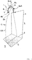
- eine schematische, perspektivische Darstellung eines Strahlers zum Beleuchten von aneinander grenzenden Wand- und Bodenflächen, wobei in der
Fig. 1 nur der unreflektiert abgestrahlte Direktlichtanteil, der ein Flächenstück auf dem Boden bestrahlt, dargestellt ist, wobei die Umlenkoptik des Strahlers einen Reflektor umfasst und den hiervon unreflektiert abgestrahlten Direktlichtanteil zeigt, - Fig. 2:
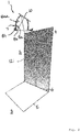
- eine schematische Darstellung des Strahlers aus
Fig. 1 in einer perspektivischen Ansicht, wobei nur der das Flächenstück auf der Wand beleuchtende Indirektlichtanteil dargestellt ist, und - Fig. 3:
- eine schematische Darstellung des Strahlers aus
Fig. 1 in einer perspektivischen Ansicht, wobei nur der das Flächenstück auf dem Boden beleuchtende Indirektlichtanteil dargestellt ist. - Wie die Figuren zeigen, kann die Beleuchtungsvorrichtung einen Strahler 1 umfassen, der zwei zueinander winkelig angeordnete Flächen beispielsweise in Form einer aufrechten Wand 2 und eines liegenden Bodens 3 bestrahlt, wobei der Strahler 1 genauer gesagt jeweils Flächenstücke 4 und 5 auf der genannten Wand 2 und dem Boden 3 bestrahlt, die aneinander angrenzen und sozusagen über den Falz 6 bzw. den winkeligen Übergang zwischen Wand 2 und Boden 3 hinweggehen.
- Wie
Fig. 1 zeigt, können die genannten Flächenstücke 4 und 5 jeweils rechteckig ausgebildet sein, was durch eine entsprechende Ausbildung bzw. Konturierung der Umlenkoptik 7 erreicht wird, die noch näher erläutert wird. - Wie
Fig. 1 zeigt, umfasst die Umlenkoptik 7 einen Reflektor 8, der von einer Lichtquelle 10 abgegebenes Licht einfängt und in ein Strahlenbündel transformiert, das sowohl die Wand 2 als auch den Boden 3 bzw. die darauf liegenden Flächenstücke 4 und 5 beleuchtet. - Als Lichtquelle 10 kann beispielsweise eine LED vorgesehen sein, die auf einer Leiterplatte 11 oder einem anderen Lichtquellenträger vorgesehen sein kann, wobei der genannte Reflektor 8 auf der besagten Leiterplatte 11 sitzen und die Lichtquelle 10 umschließen kann. Gegebenenfalls kann der Strahler 1 auch mehr als eine Lichtquelle 10 umfassen, beispielsweise mehrere nebeneinander angeordnete LEDs, die verschiedene Farben oder auch dieselbe Farbe haben können.
- Der Strahler 1 kann vorteilhafterweise am oberen Endbereich der zu beleuchtenden Wand 2 von dieser beabstandet angeordnet sein, beispielsweise an einer angrenzenden Decke montiert sein, wobei der genannte Strahler 1 deckenbündig und/oder versenkt in die genannte Decke montiert sein kann, wie dies beispielsweise von Downlights oder Wallwashern an sich bekannt ist.
- Der Strahler 1 besitzt dabei eine nach unten auf den Boden 3 und/oder die Wand 2 zu gerichtete Hauptabstrahlrichtung, wobei insbesondere der genannte Reflektor 8 nach unten auf den Boden und/oder die Wand 2 "schauen" kann. Vorteilhafterweise kann die Lichtquelle 1 und/oder die Leiterplatte 11, auf der die Lichtquelle 10 angeordnet ist, geneigt unter einem spitzen Winkel zur Decke und/oder spitzwinklig geneigt zur Fläche des Bodens 3 positioniert sein, insbesondere derart, dass die Höhe der Leiterplatte 11 mit zunehmendem Abstand von der Wand 2 zunimmt. Grundsätzlich wäre auch eine decken- und/oder bodenparallele Anordnung möglich. Durch eine Schrägstellung der Platine bzw. der Leiterplatte 11 kann jedoch eine flexiblere Lichtstromaufteilung zwischen Wand 2 und Boden 3 erzielt werden.
- Der Reflektor 8 umfasst eine lichttechnisch aktive Reflektorfläche 8a, die von der napfförmigen Innenkontur des Reflektors 8 gebildet sein kann, sowie optional einen lichttechnisch nicht aktiven, die genannte Reflektorfläche 8a einfassenden Kragen 8k, wobei der Übergang zwischen dem genannten Kragen 8k und der lichttechnisch aktiven Reflektorfläche 8a die Abrisskante 8b bildet, die den unreflektiert aus dem Reflektor 8 austretenden Direktlichtanteil 12d des Strahlenbündels 12 begrenzt, vgl.
Fig. 1a . - Die Lichtquelle 10 kann zum Reflektor 8 derart angeordnet sein, dass die Lichtquelle 10 in einen Halbraum abstrahlt, der vom Boden des Reflektors 8 über dessen Austrittsquerschnitt hinausgeht. Mit anderen Worten kann die Lichtquelle 10 aus dem Reflektor 8 herausstrahlen, so dass es zu dem genannten Direktlichtanteil 12d kommt.
- Zum anderen fällt ein Teil des von der Lichtquelle 10 abgestrahlten Lichts auf die lichttechnisch aktive Reflektorfläche 8a, von der dieses Licht reflektiert und abgestrahlt wird. Der Reflektor 8 ist hierbei einfach reflektierend ausgebildet, so dass das von der Lichtquelle 10 abgegebene Licht maximal einmal an dem Reflektor 8 reflektiert wird.
- Wie
Fig. 1 zeigt, ist der Reflektor 8 mit seiner Abrisskante 8b derart konturiert, dass der Direktlichtanteil 12d des Strahlenbündels 12 ausschließlich auf den Boden 3 fällt, wobei sich der Rand des vom Direktlichtanteil 12d beleuchteten Flächenstücks 5 im Falz 6 bzw. im winkeligen Übergangsbereich zwischen Boden 3 und Wand 2 befindet. Der genannte Reflektor 8 bildet mit seiner Abrisskante 8b eine umlaufende Abblendkontur, die die Wand 2 gegenüber dem Direktlichtanteil 12d abblendet und den Direktlichtanteil 12d am Boden 3 auf das Flächenstück 5 begrenzt. - Zum anderen ist der Reflektor 8 mit seiner lichttechnisch aktiven, reflektierenden Reflektorfläche 8a derart konturiert, dass der reflektierte Indirektlichtanteil 12i einerseits das genannte Flächenstück 5 auf dem Boden 3 und andererseits das Flächenstück 4 auf der Wand 2 bestrahlt.
- Der Reflektor 8 ist hierbei mehrschalig ausgebildet und/oder in mehrere Segmente unterteilt, so dass ein erstes Reflektorflächensegment 8aa das Flächenstück 4 auf der Wand 2 bestrahlt, vgl.
Fig. 2(a) , und ein zweites Reflektorflächensegment 8ab das Flächenstück 5 auf dem Boden 3 bestrahlt, vgl.Fig. 3(a) . - Die genannten Reflektorflächensegmente 8aa und 8ab bzw. allgemein die lichttechnisch aktive Reflektorfläche 8a des Reflektors 8 sind hierbei vorteilhafterweise derart konturiert, dass der Indirektlichtanteil 12i einerseits das Flächenstück 5 vollständig ausleuchtet, d.h. ein Flächenstück 5 bestrahlt, das im Wesentlichen kongruent oder deckungsgleich zu dem Flächenstück 5 ist, das von dem Direktlichtanteil 12d bestrahlt wird. Zum anderen bestrahlt die Reflektorfläche 8a, insbesondere deren Segment 8aa das Flächenstück 4 auf der Wand 2. Die genannten Segmente 8aa und 8ab können dabei derart beschaffen sein, dass jedes Segment nur jeweils eines der beiden genannten Flächenstücke 4 und 5 bestrahlt. Alternativ kann auch eine überlappende Bestrahlung vorgesehen sein, insbesondere derart, dass jedes der genannten Reflektorflächensegmente 8aa und 8ab jeweils vollständig beide Flächenstücke 4 und 5 bestrahlt. Auch Mischformen sind möglich, beispielsweise dergestalt, dass das erste Reflektorflächensegment 8aa vollständig das Flächenstück 4 auf der Wand 2 und einen Teil des Flächenstücks 5 auf dem Boden 3 bestrahlt, während umgekehrt das andere Reflektorflächensegment 8ab vollständig das Flächenstück 5 auf dem Boden 3 und einen Teil des Flächenstücks 4 auf der Wand 2 bestrahlt.
Claims (13)
- Vorrichtung zum Beleuchten zweier zueinander winkelig angeordneter Flächen, die Wand- und Bodenflächen (2, 3) bilden und über den winkeligen Übergang (6) zwischen der aufrechten Wand und dem angrenzenden Boden hinweggehen, mit zumindest einem Strahler (1), der am oberen Endbereich der zu beleuchtenden Wandfläche (2) von dieser beabstandet angeordnet ist und zumindest eine Lichtquelle (10) und eine Umlenkoptik (7) umfassend einen Reflektor (8) aufweist, wobei die Umlenkoptik (7) von der Lichtquelle (10) abgegebenes Licht einfängt und in Form eines Strahlenbündels (12) auf beiden Flächen abstrahlt, so dass auf beiden Flächen jeweils ein Flächenstück (4, 5) beleuchtet ist, wobei das Strahlenbündel (12) einen von der Umlenkoptik (7) reflektierten Indirektlichtanteil (12i) und einen von der Umlenkoptik (7) unreflektierten Direktlichtanteil (12d) umfasst, wobei der Direktlichtanteil (12d) nur auf eine der beiden Flächen fällt, dadurch gekennzeichnet, dass die Umlenkoptik (7) dazu ausgebildet ist, den unreflektierten Direktlichtanteil (12d) so zu begrenzen, dass sich ein Rand des vom Direktlichtanteil (12d) bestrahlten Flächenstücks (5) entlang des winkeligen Übergangs (6) zwischen den beiden Flächen erstreckt, wobei der Indirektlichtanteil (12i) und der Direktlichtanteil (12d) einander teilweise überlagert sind, wobei die Umlenkoptik (7) einen mehrschaligen und/oder in mehrere Segmente unterteilten Reflektor (8) umfasst, wobei ein erstes Reflektorflächensegment (8aa) das eingefangene Licht in einen Indirektlichtanteil transformiert, der das Flächenstück (4) auf einer ersten der beiden Flächen bestrahlt, während ein zweites Reflektorflächensegment (8ab) das eingefangene Licht in einen Indirektlichtanteil transformiert, der das Flächenstück (5) auf der anderen der beiden Flächen bestrahlt.
- Vorrichtung nach dem vorhergehenden Anspruch, wobei der Direktlichtanteil (12d) von einer Abrisskante (8b) des Reflektors (8) begrenzt wird, die derart konturiert ist, dass der Direktlichtanteil (12d) nur auf die eine der beiden Flächen fällt und sich der Rand des vom Direktlichtanteil bestrahlten Flächenstücks (5) entlang des winkeligen Übergangs (6) zwischen den beiden Flächen erstreckt.
- Vorrichtung zum Beleuchten zweier zueinander winkelig angeordneter Flächen, die Wand- und Bodenflächen (2, 3) bilden und über den winkeligen Übergang (6) zwischen der aufrechten Wand und dem angrenzenden Boden hinweggehen, mit zumindest einem Strahler (1), der am oberen Endbereich der zu beleuchtenden Wandfläche (2) von dieser beabstandet angeordnet ist und zumindest eine Lichtquelle (10) und eine Umlenkoptik (7) umfassend eine Linse (9) aufweist, wobei die Umlenkoptik (7) von der Lichtquelle (10) abgegebenes Licht einfängt und in Form eines Strahlenbündels (12) auf beiden Flächen abstrahlt, so dass auf beiden Flächen jeweils ein Flächenstück (4, 5) beleuchtet ist, wobei das Strahlenbündel (12) einen von der Umlenkoptik (7) reflektierten Indirektlichtanteil (12i) und einen von der Umlenkoptik (7) unreflektierten Direktlichtanteil (12d) umfasst, wobei der Direktlichtanteil (12d) nur auf eine der beiden Flächen fällt, dadurch gekennzeichnet, dass die Umlenkoptik (7) dazu ausgebildet ist, den unreflektierten Direktlichtanteil (12d) so zu begrenzen, dass sich ein Rand des vom Direktlichtanteil (12d) bestrahlten Flächenstücks (5) entlang des winkeligen Übergangs (6) zwischen den beiden Flächen erstreckt, wobei der Indirektlichtanteil (12i) und der Direktlichtanteil (12d) einander teilweise überlagert sind, wobei die genannte Linse (9) in mehrere Linsensegmente unterteilt ist, wobei ein erstes Linsenmantelflächensegment das eingefangene Licht in einem Indirektlichtanteil (12i) transformiert, der das Flächenstück (4) auf einer ersten der beiden Flächen bestrahlt, während ein zweites Linsenmantelflächensegment das eingefangene Licht in einen Indirektlichtanteil (12i) transformiert, der das Flächenstück (5) auf der anderen der beiden Flächen bestrahlt.
- Vorrichtung nach einem der' vorhergehenden Ansprüche, wobei die Umlenkoptik (7), insbesondere eine lichttechnisch aktive Reflektorfläche (8ab) des Reflektors (8) oder eine Mantelfläche der Linse (9) im Zusammenspiel mit deren Lichteintritts- und -austrittsflächen (13, 14), dazu ausgebildet ist, den reflektierten Indirektlichtanteil (12i) auf das gesamte Flächenstück (5) zu verteilen, das auch von dem Direktlichtanteil (12d) bestrahlt ist.
- Vorrichtung nach einem der vorhergehenden Ansprüche, wobei die Umlenkoptik (7) dazu ausgebildet ist, den Indirektlichtanteil auf der vom Direktlichtanteil (12d) bestrahlten Fläche so zu verteilen, dass die vom Direktlichtanteil (12d) und vom Indirektlichtanteil (12i) jeweils bestrahlten Flächenstücke zumindest näherungsweise deckungsgleich sind.
- Vorrichtung nach einem der vorhergehenden Ansprüche, wobei die Umlenkoptik (7) dazu ausgebildet ist, den Direktlichtanteil (12d) auf die Bodenfläche (3) zu werfen und den Indirektlichtanteil (12i) auf die genannte Bodenfläche (3) und die angrenzende Wandfläche (2) zu werfen.
- Vorrichtung nach dem vorhergehenden Anspruch, wobei der Strahler (1) an einer Decke von der angrenzenden Wandfläche (2) beabstandet angeordnet, insbesondere deckenbündig versenkt eingebaut, ist und eine nach unten auf den Boden (3) und/oder die Wand (2) zu gerichtete Hauptabstrahlrichtung besitzt, wobei die Wandfläche (2) spitzwinklig schleifend bestrahlt und die Bodenfläche (3) zumindest näherungsweise frontal bestrahlt wird.
- Vorrichtung nach einem der beiden vorhergehenden Ansprüche, wobei die Umlenkoptik (7) dazu ausgebildet ist, den Indirektlichtanteil (12i) auf die angrenzende Wandfläche (2) mit einer gleichmäßigen Lichtstärkeverteilung im Wesentlichen über die gesamte Höhe der Wandfläche (2) vom Boden (3) bis zur Höhe des Strahlers (1) zu verteilen.
- Vorrichtung nach einem der' vorhergehenden Ansprüche, wobei die Umlenkoptik (7) einfach reflektierend ausgebildet ist und das gesamte von der Lichtquelle (10) abgegebene und von der Umlenkoptik (7) eingefangene Licht maximal einmal reflektiert ist.
- Vorrichtung nach einem der vorhergehenden Ansprüche, wobei zumindest eine lichttechnisch aktive Oberfläche der Umlenkoptik (7) mit einer Facettierung und/oder Mikrostrukturierung versehen ist.
- Vorrichtung nach einem der vorhergehenden Ansprüche, wobei die Umlenkoptik (7) derart konturiert ist, dass die von dem Direktlichtanteil (12d) und dem Indirektlichtanteil (12i) bestrahlten Flächenstücke (4, 5) auf den zueinander winkeligen Flächen jeweils rechteckige Außenkonturen besitzen.
- Vorrichtung nach Anspruch 7 oder einem der darauf rückbezogenen Ansprüche, wobei die zumindest eine Lichtquelle (10) und/oder eine die Lichtquelle (10) tragende Leiterplatte (11) zu beiden bestrahlten Flächen spitzwinklig geneigt angeordnet ist derart, dass sich eine Hauptachse, die durch die Lichtquelle (10) geht und/oder senkrecht zur Leiterplatte (11) ausgerichtet ist, von der schleifend bestrahlten Wandfläche (2) einen zunehmend größeren Abstand besitzt, je näher die genannte Hauptachse der anderen, frontal bestrahlten Bodenfläche (3) kommt.
- Vorrichtung nach Anspruch 7 oder einem der darauf rückbezogenen Ansprüche 1 bis 11, wobei die zumindest eine Lichtquelle (10) und/oder eine die Lichtquelle (10) tragende Leiterplatte (11) zu beiden bestrahlten Flächen spitzwinklig geneigt angeordnet ist derart, dass sich eine Hauptachse, die durch die Lichtquelle (10) geht und/oder senkrecht zur Leiterplatte (11) ausgerichtet ist, von der schleifend bestrahlten Wandfläche (2) einen zunehmend kleineren Abstand besitzt, je näher die genannte Hauptachse der anderen, frontal bestrahlten Bodenfläche (3) kommt.
Applications Claiming Priority (1)
| Application Number | Priority Date | Filing Date | Title |
|---|---|---|---|
| DE102016012336.2A DE102016012336A1 (de) | 2016-10-14 | 2016-10-14 | Vorrichtung zum Beleuchten von zueinander winkelig angeordneten Flächen |
Publications (2)
| Publication Number | Publication Date |
|---|---|
| EP3309450A1 EP3309450A1 (de) | 2018-04-18 |
| EP3309450B1 true EP3309450B1 (de) | 2020-12-30 |
Family
ID=60051402
Family Applications (1)
| Application Number | Title | Priority Date | Filing Date |
|---|---|---|---|
| EP17195402.7A Active EP3309450B1 (de) | 2016-10-14 | 2017-10-09 | Vorrichtung zum beleuchten von zueinander winkelig angeordneten flächen |
Country Status (3)
| Country | Link |
|---|---|
| EP (1) | EP3309450B1 (de) |
| DE (1) | DE102016012336A1 (de) |
| PT (1) | PT3309450T (de) |
Families Citing this family (1)
| Publication number | Priority date | Publication date | Assignee | Title |
|---|---|---|---|---|
| US12655952B2 (en) * | 2022-03-14 | 2026-06-16 | Usai, Llc | Flush glass adjustable lighting fixture |
Family Cites Families (7)
| Publication number | Priority date | Publication date | Assignee | Title |
|---|---|---|---|---|
| GB2438636A (en) * | 2006-05-31 | 2007-12-05 | Paul Francis Thurgood | Ceiling tile with integrated LED |
| EP2142845A4 (de) * | 2007-05-07 | 2011-04-20 | David A Venhaus | Optisches festkörpersystem |
| DE102007035528B9 (de) * | 2007-07-26 | 2012-02-09 | Erco Gmbh | Leuchte |
| DE102007044963B4 (de) * | 2007-07-26 | 2013-03-28 | Erco Gmbh | Leuchte |
| KR101048801B1 (ko) * | 2008-04-04 | 2011-07-12 | 주식회사 아모럭스 | 벽면 조명용 케이싱 및 이를 사용한 발광 다이오드 조명 기구 |
| US9234640B2 (en) * | 2012-08-30 | 2016-01-12 | Juno Manufacturing, LLC | Wall-wash fixture for directional light sources |
| US20150247622A1 (en) * | 2014-02-28 | 2015-09-03 | Juno Manufacturing Llc | Extended lens optics for wall wash lighting |
-
2016
- 2016-10-14 DE DE102016012336.2A patent/DE102016012336A1/de not_active Withdrawn
-
2017
- 2017-10-09 EP EP17195402.7A patent/EP3309450B1/de active Active
- 2017-10-09 PT PT171954027T patent/PT3309450T/pt unknown
Non-Patent Citations (1)
| Title |
|---|
| None * |
Also Published As
| Publication number | Publication date |
|---|---|
| PT3309450T (pt) | 2021-03-30 |
| DE102016012336A1 (de) | 2018-04-19 |
| EP3309450A1 (de) | 2018-04-18 |
Similar Documents
| Publication | Publication Date | Title |
|---|---|---|
| EP2678603B1 (de) | Beleuchtungsvorrichtung | |
| DE102008014317A1 (de) | Leuchte mit getrennten Leuchtmitteln für Direktbeleuchtung und Indirektbeleuchtung | |
| EP3012521B1 (de) | Leuchte für ein kraftfahrzeug | |
| AT514121B1 (de) | Leuchteinheit für einen Fahrzeugscheinwerfer sowie Fahrzeugscheinwerfer | |
| EP3369988B1 (de) | Verfahren und beleuchtungsvorrichtung zum beleuchten von wandflächen | |
| DE102014202774A1 (de) | Deckenverkleidungselement für eine Innenverkleidungsanordnung einer Flugzeugkabine | |
| EP3042120B1 (de) | Anordnung zur lichtabgabe | |
| EP3092439A2 (de) | Leuchtvorrichtung | |
| EP3023689B1 (de) | Leuchtvorrichtung | |
| EP3309450A1 (de) | Vorrichtung zum beleuchten von zueinander winkelig angeordneten flächen | |
| EP3408587B1 (de) | Optisches system zum beeinflussen der lichtabgabe einer lichtquelle | |
| EP3540299B1 (de) | Leuchte | |
| DE102007038205A1 (de) | Leuchte | |
| DE102013207663A1 (de) | LED-Leuchte mit unterschiedlich einstellbaren Lichtverteilungen | |
| CH710609A1 (de) | Leuchte mit Primär- und Sekundärabstrahlungsrichtung. | |
| EP2860444B1 (de) | LED-Rasterleuchte | |
| EP3359874B1 (de) | Anordnung zur lichtabgabe | |
| EP3263974A1 (de) | Lochstrahler | |
| EP4155605A1 (de) | Strahler | |
| EP4063728A1 (de) | Leuchte | |
| DE102004063635A1 (de) | Beleuchtungsanordnung | |
| DE102022130698A1 (de) | Verfahren und Beleuchtungsvorrichtung zum Beleuchten von Wandflächen | |
| EP3519729A1 (de) | Optisches system für eine leuchte, sowie leuchte | |
| DE202013010472U1 (de) | Aufhängung für Strahler mit Beleuchtungszweck | |
| EP2924346A1 (de) | Optik für eine Leuchte |
Legal Events
| Date | Code | Title | Description |
|---|---|---|---|
| PUAI | Public reference made under article 153(3) epc to a published international application that has entered the european phase |
Free format text: ORIGINAL CODE: 0009012 |
|
| STAA | Information on the status of an ep patent application or granted ep patent |
Free format text: STATUS: THE APPLICATION HAS BEEN PUBLISHED |
|
| AK | Designated contracting states |
Kind code of ref document: A1 Designated state(s): AL AT BE BG CH CY CZ DE DK EE ES FI FR GB GR HR HU IE IS IT LI LT LU LV MC MK MT NL NO PL PT RO RS SE SI SK SM TR |
|
| AX | Request for extension of the european patent |
Extension state: BA ME |
|
| STAA | Information on the status of an ep patent application or granted ep patent |
Free format text: STATUS: REQUEST FOR EXAMINATION WAS MADE |
|
| 17P | Request for examination filed |
Effective date: 20181018 |
|
| RBV | Designated contracting states (corrected) |
Designated state(s): AL AT BE BG CH CY CZ DE DK EE ES FI FR GB GR HR HU IE IS IT LI LT LU LV MC MK MT NL NO PL PT RO RS SE SI SK SM TR |
|
| STAA | Information on the status of an ep patent application or granted ep patent |
Free format text: STATUS: EXAMINATION IS IN PROGRESS |
|
| 17Q | First examination report despatched |
Effective date: 20190522 |
|
| GRAP | Despatch of communication of intention to grant a patent |
Free format text: ORIGINAL CODE: EPIDOSNIGR1 |
|
| STAA | Information on the status of an ep patent application or granted ep patent |
Free format text: STATUS: GRANT OF PATENT IS INTENDED |
|
| INTG | Intention to grant announced |
Effective date: 20200715 |
|
| GRAS | Grant fee paid |
Free format text: ORIGINAL CODE: EPIDOSNIGR3 |
|
| GRAA | (expected) grant |
Free format text: ORIGINAL CODE: 0009210 |
|
| STAA | Information on the status of an ep patent application or granted ep patent |
Free format text: STATUS: THE PATENT HAS BEEN GRANTED |
|
| AK | Designated contracting states |
Kind code of ref document: B1 Designated state(s): AL AT BE BG CH CY CZ DE DK EE ES FI FR GB GR HR HU IE IS IT LI LT LU LV MC MK MT NL NO PL PT RO RS SE SI SK SM TR |
|
| REG | Reference to a national code |
Ref country code: GB Ref legal event code: FG4D Free format text: NOT ENGLISH |
|
| REG | Reference to a national code |
Ref country code: AT Ref legal event code: REF Ref document number: 1350292 Country of ref document: AT Kind code of ref document: T Effective date: 20210115 |
|
| REG | Reference to a national code |
Ref country code: DE Ref legal event code: R096 Ref document number: 502017008819 Country of ref document: DE |
|
| REG | Reference to a national code |
Ref country code: IE Ref legal event code: FG4D Free format text: LANGUAGE OF EP DOCUMENT: GERMAN |
|
| REG | Reference to a national code |
Ref country code: PT Ref legal event code: SC4A Ref document number: 3309450 Country of ref document: PT Date of ref document: 20210330 Kind code of ref document: T Free format text: AVAILABILITY OF NATIONAL TRANSLATION Effective date: 20210323 |
|
| PG25 | Lapsed in a contracting state [announced via postgrant information from national office to epo] |
Ref country code: NO Free format text: LAPSE BECAUSE OF FAILURE TO SUBMIT A TRANSLATION OF THE DESCRIPTION OR TO PAY THE FEE WITHIN THE PRESCRIBED TIME-LIMIT Effective date: 20210330 Ref country code: RS Free format text: LAPSE BECAUSE OF FAILURE TO SUBMIT A TRANSLATION OF THE DESCRIPTION OR TO PAY THE FEE WITHIN THE PRESCRIBED TIME-LIMIT Effective date: 20201230 Ref country code: FI Free format text: LAPSE BECAUSE OF FAILURE TO SUBMIT A TRANSLATION OF THE DESCRIPTION OR TO PAY THE FEE WITHIN THE PRESCRIBED TIME-LIMIT Effective date: 20201230 Ref country code: GR Free format text: LAPSE BECAUSE OF FAILURE TO SUBMIT A TRANSLATION OF THE DESCRIPTION OR TO PAY THE FEE WITHIN THE PRESCRIBED TIME-LIMIT Effective date: 20210331 |
|
| REG | Reference to a national code |
Ref country code: CH Ref legal event code: NV Representative=s name: KELLER SCHNEIDER PATENT- UND MARKENANWAELTE AG, CH |
|
| PG25 | Lapsed in a contracting state [announced via postgrant information from national office to epo] |
Ref country code: SE Free format text: LAPSE BECAUSE OF FAILURE TO SUBMIT A TRANSLATION OF THE DESCRIPTION OR TO PAY THE FEE WITHIN THE PRESCRIBED TIME-LIMIT Effective date: 20201230 Ref country code: BG Free format text: LAPSE BECAUSE OF FAILURE TO SUBMIT A TRANSLATION OF THE DESCRIPTION OR TO PAY THE FEE WITHIN THE PRESCRIBED TIME-LIMIT Effective date: 20210330 Ref country code: LV Free format text: LAPSE BECAUSE OF FAILURE TO SUBMIT A TRANSLATION OF THE DESCRIPTION OR TO PAY THE FEE WITHIN THE PRESCRIBED TIME-LIMIT Effective date: 20201230 |
|
| REG | Reference to a national code |
Ref country code: NL Ref legal event code: MP Effective date: 20201230 |
|
| PG25 | Lapsed in a contracting state [announced via postgrant information from national office to epo] |
Ref country code: HR Free format text: LAPSE BECAUSE OF FAILURE TO SUBMIT A TRANSLATION OF THE DESCRIPTION OR TO PAY THE FEE WITHIN THE PRESCRIBED TIME-LIMIT Effective date: 20201230 |
|
| REG | Reference to a national code |
Ref country code: LT Ref legal event code: MG9D |
|
| PG25 | Lapsed in a contracting state [announced via postgrant information from national office to epo] |
Ref country code: RO Free format text: LAPSE BECAUSE OF FAILURE TO SUBMIT A TRANSLATION OF THE DESCRIPTION OR TO PAY THE FEE WITHIN THE PRESCRIBED TIME-LIMIT Effective date: 20201230 Ref country code: SK Free format text: LAPSE BECAUSE OF FAILURE TO SUBMIT A TRANSLATION OF THE DESCRIPTION OR TO PAY THE FEE WITHIN THE PRESCRIBED TIME-LIMIT Effective date: 20201230 Ref country code: EE Free format text: LAPSE BECAUSE OF FAILURE TO SUBMIT A TRANSLATION OF THE DESCRIPTION OR TO PAY THE FEE WITHIN THE PRESCRIBED TIME-LIMIT Effective date: 20201230 Ref country code: CZ Free format text: LAPSE BECAUSE OF FAILURE TO SUBMIT A TRANSLATION OF THE DESCRIPTION OR TO PAY THE FEE WITHIN THE PRESCRIBED TIME-LIMIT Effective date: 20201230 Ref country code: LT Free format text: LAPSE BECAUSE OF FAILURE TO SUBMIT A TRANSLATION OF THE DESCRIPTION OR TO PAY THE FEE WITHIN THE PRESCRIBED TIME-LIMIT Effective date: 20201230 |
|
| PG25 | Lapsed in a contracting state [announced via postgrant information from national office to epo] |
Ref country code: PL Free format text: LAPSE BECAUSE OF FAILURE TO SUBMIT A TRANSLATION OF THE DESCRIPTION OR TO PAY THE FEE WITHIN THE PRESCRIBED TIME-LIMIT Effective date: 20201230 |
|
| PG25 | Lapsed in a contracting state [announced via postgrant information from national office to epo] |
Ref country code: IS Free format text: LAPSE BECAUSE OF FAILURE TO SUBMIT A TRANSLATION OF THE DESCRIPTION OR TO PAY THE FEE WITHIN THE PRESCRIBED TIME-LIMIT Effective date: 20210430 |
|
| REG | Reference to a national code |
Ref country code: DE Ref legal event code: R097 Ref document number: 502017008819 Country of ref document: DE |
|
| PG25 | Lapsed in a contracting state [announced via postgrant information from national office to epo] |
Ref country code: AL Free format text: LAPSE BECAUSE OF FAILURE TO SUBMIT A TRANSLATION OF THE DESCRIPTION OR TO PAY THE FEE WITHIN THE PRESCRIBED TIME-LIMIT Effective date: 20201230 |
|
| PLBE | No opposition filed within time limit |
Free format text: ORIGINAL CODE: 0009261 |
|
| STAA | Information on the status of an ep patent application or granted ep patent |
Free format text: STATUS: NO OPPOSITION FILED WITHIN TIME LIMIT |
|
| PG25 | Lapsed in a contracting state [announced via postgrant information from national office to epo] |
Ref country code: DK Free format text: LAPSE BECAUSE OF FAILURE TO SUBMIT A TRANSLATION OF THE DESCRIPTION OR TO PAY THE FEE WITHIN THE PRESCRIBED TIME-LIMIT Effective date: 20201230 |
|
| 26N | No opposition filed |
Effective date: 20211001 |
|
| PG25 | Lapsed in a contracting state [announced via postgrant information from national office to epo] |
Ref country code: ES Free format text: LAPSE BECAUSE OF FAILURE TO SUBMIT A TRANSLATION OF THE DESCRIPTION OR TO PAY THE FEE WITHIN THE PRESCRIBED TIME-LIMIT Effective date: 20201230 |
|
| PG25 | Lapsed in a contracting state [announced via postgrant information from national office to epo] |
Ref country code: SI Free format text: LAPSE BECAUSE OF FAILURE TO SUBMIT A TRANSLATION OF THE DESCRIPTION OR TO PAY THE FEE WITHIN THE PRESCRIBED TIME-LIMIT Effective date: 20201230 |
|
| PG25 | Lapsed in a contracting state [announced via postgrant information from national office to epo] |
Ref country code: IS Free format text: LAPSE BECAUSE OF FAILURE TO SUBMIT A TRANSLATION OF THE DESCRIPTION OR TO PAY THE FEE WITHIN THE PRESCRIBED TIME-LIMIT Effective date: 20210430 |
|
| PG25 | Lapsed in a contracting state [announced via postgrant information from national office to epo] |
Ref country code: MC Free format text: LAPSE BECAUSE OF FAILURE TO SUBMIT A TRANSLATION OF THE DESCRIPTION OR TO PAY THE FEE WITHIN THE PRESCRIBED TIME-LIMIT Effective date: 20201230 |
|
| PG25 | Lapsed in a contracting state [announced via postgrant information from national office to epo] |
Ref country code: LU Free format text: LAPSE BECAUSE OF NON-PAYMENT OF DUE FEES Effective date: 20211009 |
|
| PG25 | Lapsed in a contracting state [announced via postgrant information from national office to epo] |
Ref country code: IE Free format text: LAPSE BECAUSE OF NON-PAYMENT OF DUE FEES Effective date: 20211009 |
|
| PG25 | Lapsed in a contracting state [announced via postgrant information from national office to epo] |
Ref country code: HU Free format text: LAPSE BECAUSE OF FAILURE TO SUBMIT A TRANSLATION OF THE DESCRIPTION OR TO PAY THE FEE WITHIN THE PRESCRIBED TIME-LIMIT; INVALID AB INITIO Effective date: 20171009 |
|
| PG25 | Lapsed in a contracting state [announced via postgrant information from national office to epo] |
Ref country code: NL Free format text: LAPSE BECAUSE OF NON-PAYMENT OF DUE FEES Effective date: 20201230 Ref country code: CY Free format text: LAPSE BECAUSE OF FAILURE TO SUBMIT A TRANSLATION OF THE DESCRIPTION OR TO PAY THE FEE WITHIN THE PRESCRIBED TIME-LIMIT Effective date: 20201230 |
|
| PG25 | Lapsed in a contracting state [announced via postgrant information from national office to epo] |
Ref country code: SM Free format text: LAPSE BECAUSE OF FAILURE TO SUBMIT A TRANSLATION OF THE DESCRIPTION OR TO PAY THE FEE WITHIN THE PRESCRIBED TIME-LIMIT Effective date: 20201230 |
|
| PG25 | Lapsed in a contracting state [announced via postgrant information from national office to epo] |
Ref country code: MK Free format text: LAPSE BECAUSE OF FAILURE TO SUBMIT A TRANSLATION OF THE DESCRIPTION OR TO PAY THE FEE WITHIN THE PRESCRIBED TIME-LIMIT Effective date: 20201230 |
|
| PG25 | Lapsed in a contracting state [announced via postgrant information from national office to epo] |
Ref country code: TR Free format text: LAPSE BECAUSE OF FAILURE TO SUBMIT A TRANSLATION OF THE DESCRIPTION OR TO PAY THE FEE WITHIN THE PRESCRIBED TIME-LIMIT Effective date: 20201230 |
|
| PG25 | Lapsed in a contracting state [announced via postgrant information from national office to epo] |
Ref country code: MT Free format text: LAPSE BECAUSE OF FAILURE TO SUBMIT A TRANSLATION OF THE DESCRIPTION OR TO PAY THE FEE WITHIN THE PRESCRIBED TIME-LIMIT Effective date: 20201230 |
|
| REG | Reference to a national code |
Ref country code: CH Ref legal event code: U11 Free format text: ST27 STATUS EVENT CODE: U-0-0-U10-U11 (AS PROVIDED BY THE NATIONAL OFFICE) Effective date: 20251101 |
|
| PGFP | Annual fee paid to national office [announced via postgrant information from national office to epo] |
Ref country code: PT Payment date: 20251008 Year of fee payment: 9 |
|
| PGFP | Annual fee paid to national office [announced via postgrant information from national office to epo] |
Ref country code: DE Payment date: 20251028 Year of fee payment: 9 |
|
| PGFP | Annual fee paid to national office [announced via postgrant information from national office to epo] |
Ref country code: GB Payment date: 20251024 Year of fee payment: 9 |
|
| PGFP | Annual fee paid to national office [announced via postgrant information from national office to epo] |
Ref country code: AT Payment date: 20251023 Year of fee payment: 9 |
|
| PGFP | Annual fee paid to national office [announced via postgrant information from national office to epo] |
Ref country code: IT Payment date: 20251030 Year of fee payment: 9 |
|
| PGFP | Annual fee paid to national office [announced via postgrant information from national office to epo] |
Ref country code: FR Payment date: 20251024 Year of fee payment: 9 |
|
| PGFP | Annual fee paid to national office [announced via postgrant information from national office to epo] |
Ref country code: BE Payment date: 20251024 Year of fee payment: 9 |
|
| PGFP | Annual fee paid to national office [announced via postgrant information from national office to epo] |
Ref country code: CH Payment date: 20251101 Year of fee payment: 9 |