EP3308829B1 - Elektrostimulative transplantatprodukte - Google Patents
Elektrostimulative transplantatprodukte Download PDFInfo
- Publication number
- EP3308829B1 EP3308829B1 EP17190216.6A EP17190216A EP3308829B1 EP 3308829 B1 EP3308829 B1 EP 3308829B1 EP 17190216 A EP17190216 A EP 17190216A EP 3308829 B1 EP3308829 B1 EP 3308829B1
- Authority
- EP
- European Patent Office
- Prior art keywords
- graft
- anode
- cathode
- tissue
- metal
- Prior art date
- Legal status (The legal status is an assumption and is not a legal conclusion. Google has not performed a legal analysis and makes no representation as to the accuracy of the status listed.)
- Active
Links
- 210000001519 tissue Anatomy 0.000 claims description 55
- 229910052751 metal Inorganic materials 0.000 claims description 47
- 239000002184 metal Substances 0.000 claims description 47
- 239000011159 matrix material Substances 0.000 claims description 42
- 238000002513 implantation Methods 0.000 claims description 22
- XEEYBQQBJWHFJM-UHFFFAOYSA-N Iron Chemical compound [Fe] XEEYBQQBJWHFJM-UHFFFAOYSA-N 0.000 claims description 12
- 102000008186 Collagen Human genes 0.000 claims description 10
- 108010035532 Collagen Proteins 0.000 claims description 10
- 229920001436 collagen Polymers 0.000 claims description 10
- 229910000640 Fe alloy Inorganic materials 0.000 claims description 6
- FYYHWMGAXLPEAU-UHFFFAOYSA-N Magnesium Chemical compound [Mg] FYYHWMGAXLPEAU-UHFFFAOYSA-N 0.000 claims description 6
- 229910000861 Mg alloy Inorganic materials 0.000 claims description 6
- FAPWRFPIFSIZLT-UHFFFAOYSA-M Sodium chloride Chemical compound [Na+].[Cl-] FAPWRFPIFSIZLT-UHFFFAOYSA-M 0.000 claims description 6
- HCHKCACWOHOZIP-UHFFFAOYSA-N Zinc Chemical compound [Zn] HCHKCACWOHOZIP-UHFFFAOYSA-N 0.000 claims description 6
- 229910001297 Zn alloy Inorganic materials 0.000 claims description 6
- 239000011777 magnesium Substances 0.000 claims description 6
- 239000011701 zinc Substances 0.000 claims description 6
- 238000004806 packaging method and process Methods 0.000 claims description 5
- 239000011780 sodium chloride Substances 0.000 claims description 5
- 239000003102 growth factor Substances 0.000 claims description 4
- 229910052742 iron Inorganic materials 0.000 claims description 4
- 229910052749 magnesium Inorganic materials 0.000 claims description 4
- 229920000642 polymer Polymers 0.000 claims description 4
- 229910052725 zinc Inorganic materials 0.000 claims description 4
- 210000001691 amnion Anatomy 0.000 claims description 3
- 230000002500 effect on skin Effects 0.000 claims description 3
- 210000003195 fascia Anatomy 0.000 claims description 3
- 229920006395 saturated elastomer Polymers 0.000 claims description 2
- 239000000463 material Substances 0.000 description 95
- 210000002744 extracellular matrix Anatomy 0.000 description 35
- 102000010834 Extracellular Matrix Proteins Human genes 0.000 description 29
- 108010037362 Extracellular Matrix Proteins Proteins 0.000 description 29
- 238000000034 method Methods 0.000 description 26
- 210000004876 tela submucosa Anatomy 0.000 description 17
- 239000007943 implant Substances 0.000 description 13
- 150000002739 metals Chemical class 0.000 description 11
- 230000000975 bioactive effect Effects 0.000 description 10
- 210000001124 body fluid Anatomy 0.000 description 10
- 239000010839 body fluid Substances 0.000 description 10
- 239000012530 fluid Substances 0.000 description 9
- 238000004891 communication Methods 0.000 description 8
- 230000012010 growth Effects 0.000 description 8
- 210000005036 nerve Anatomy 0.000 description 7
- 238000010382 chemical cross-linking Methods 0.000 description 6
- 239000000126 substance Substances 0.000 description 6
- 230000003376 axonal effect Effects 0.000 description 5
- 230000018044 dehydration Effects 0.000 description 5
- 238000006297 dehydration reaction Methods 0.000 description 5
- 239000000835 fiber Substances 0.000 description 5
- 210000000944 nerve tissue Anatomy 0.000 description 5
- 230000008439 repair process Effects 0.000 description 5
- 102000003974 Fibroblast growth factor 2 Human genes 0.000 description 4
- 108090000379 Fibroblast growth factor 2 Proteins 0.000 description 4
- 230000033115 angiogenesis Effects 0.000 description 4
- 239000010405 anode material Substances 0.000 description 4
- 230000004888 barrier function Effects 0.000 description 4
- 239000010406 cathode material Substances 0.000 description 4
- -1 formaldehyde, epoxides Chemical class 0.000 description 4
- 150000002500 ions Chemical class 0.000 description 4
- 108090000623 proteins and genes Proteins 0.000 description 4
- 102000004169 proteins and genes Human genes 0.000 description 4
- 230000008467 tissue growth Effects 0.000 description 4
- 238000011282 treatment Methods 0.000 description 4
- 229920002683 Glycosaminoglycan Polymers 0.000 description 3
- HTTJABKRGRZYRN-UHFFFAOYSA-N Heparin Chemical compound OC1C(NC(=O)C)C(O)OC(COS(O)(=O)=O)C1OC1C(OS(O)(=O)=O)C(O)C(OC2C(C(OS(O)(=O)=O)C(OC3C(C(O)C(O)C(O3)C(O)=O)OS(O)(=O)=O)C(CO)O2)NS(O)(=O)=O)C(C(O)=O)O1 HTTJABKRGRZYRN-UHFFFAOYSA-N 0.000 description 3
- 230000002491 angiogenic effect Effects 0.000 description 3
- 210000004027 cell Anatomy 0.000 description 3
- 239000003795 chemical substances by application Substances 0.000 description 3
- 238000011161 development Methods 0.000 description 3
- 230000018109 developmental process Effects 0.000 description 3
- 238000005516 engineering process Methods 0.000 description 3
- 239000011888 foil Substances 0.000 description 3
- 238000004108 freeze drying Methods 0.000 description 3
- 239000007788 liquid Substances 0.000 description 3
- 230000000717 retained effect Effects 0.000 description 3
- 239000007787 solid Substances 0.000 description 3
- 230000017423 tissue regeneration Effects 0.000 description 3
- XLYOFNOQVPJJNP-UHFFFAOYSA-N water Substances O XLYOFNOQVPJJNP-UHFFFAOYSA-N 0.000 description 3
- AEMRFAOFKBGASW-UHFFFAOYSA-N Glycolic acid Chemical compound OCC(O)=O AEMRFAOFKBGASW-UHFFFAOYSA-N 0.000 description 2
- 102000010780 Platelet-Derived Growth Factor Human genes 0.000 description 2
- 108010038512 Platelet-Derived Growth Factor Proteins 0.000 description 2
- 102000016611 Proteoglycans Human genes 0.000 description 2
- 108010067787 Proteoglycans Proteins 0.000 description 2
- 102000004887 Transforming Growth Factor beta Human genes 0.000 description 2
- 108090001012 Transforming Growth Factor beta Proteins 0.000 description 2
- 229920003232 aliphatic polyester Polymers 0.000 description 2
- 210000002469 basement membrane Anatomy 0.000 description 2
- 238000006065 biodegradation reaction Methods 0.000 description 2
- 239000012620 biological material Substances 0.000 description 2
- 230000015572 biosynthetic process Effects 0.000 description 2
- 239000008280 blood Substances 0.000 description 2
- 210000004369 blood Anatomy 0.000 description 2
- 210000004204 blood vessel Anatomy 0.000 description 2
- 239000007767 bonding agent Substances 0.000 description 2
- 210000000988 bone and bone Anatomy 0.000 description 2
- 239000011248 coating agent Substances 0.000 description 2
- 238000000576 coating method Methods 0.000 description 2
- 229940088679 drug related substance Drugs 0.000 description 2
- 239000007772 electrode material Substances 0.000 description 2
- 239000002158 endotoxin Substances 0.000 description 2
- 230000006870 function Effects 0.000 description 2
- 239000003292 glue Substances 0.000 description 2
- 229920000669 heparin Polymers 0.000 description 2
- 229960002897 heparin Drugs 0.000 description 2
- 238000005470 impregnation Methods 0.000 description 2
- 230000000977 initiatory effect Effects 0.000 description 2
- 230000000968 intestinal effect Effects 0.000 description 2
- JVTAAEKCZFNVCJ-UHFFFAOYSA-N lactic acid Chemical compound CC(O)C(O)=O JVTAAEKCZFNVCJ-UHFFFAOYSA-N 0.000 description 2
- 210000004379 membrane Anatomy 0.000 description 2
- 150000007523 nucleic acids Chemical class 0.000 description 2
- 102000039446 nucleic acids Human genes 0.000 description 2
- 108020004707 nucleic acids Proteins 0.000 description 2
- 239000002245 particle Substances 0.000 description 2
- 210000000578 peripheral nerve Anatomy 0.000 description 2
- 230000000704 physical effect Effects 0.000 description 2
- 238000002360 preparation method Methods 0.000 description 2
- 238000003825 pressing Methods 0.000 description 2
- 238000006479 redox reaction Methods 0.000 description 2
- 230000004044 response Effects 0.000 description 2
- 238000002791 soaking Methods 0.000 description 2
- 210000004872 soft tissue Anatomy 0.000 description 2
- ZRKFYGHZFMAOKI-QMGMOQQFSA-N tgfbeta Chemical compound C([C@H](NC(=O)[C@H](C(C)C)NC(=O)CNC(=O)[C@H](CCC(O)=O)NC(=O)[C@H](CCCNC(N)=N)NC(=O)[C@H](CC(N)=O)NC(=O)[C@H](CC(C)C)NC(=O)[C@H]([C@@H](C)O)NC(=O)[C@H](CCC(O)=O)NC(=O)[C@H]([C@@H](C)O)NC(=O)[C@H](CC(C)C)NC(=O)CNC(=O)[C@H](C)NC(=O)[C@H](CO)NC(=O)[C@H](CCC(N)=O)NC(=O)[C@@H](NC(=O)[C@H](C)NC(=O)[C@H](C)NC(=O)[C@@H](NC(=O)[C@H](CC(C)C)NC(=O)[C@@H](N)CCSC)C(C)C)[C@@H](C)CC)C(=O)N[C@@H]([C@@H](C)O)C(=O)N[C@@H](C(C)C)C(=O)N[C@@H](CC=1C=CC=CC=1)C(=O)N[C@@H](C)C(=O)N1[C@@H](CCC1)C(=O)N[C@@H]([C@@H](C)O)C(=O)N[C@@H](CC(N)=O)C(=O)N[C@@H](CCC(O)=O)C(=O)N[C@@H](C)C(=O)N[C@@H](CC=1C=CC=CC=1)C(=O)N[C@@H](CCCNC(N)=N)C(=O)N[C@@H](C)C(=O)N[C@@H](CC(C)C)C(=O)N1[C@@H](CCC1)C(=O)N1[C@@H](CCC1)C(=O)N[C@@H](CCCNC(N)=N)C(=O)N[C@@H](CCC(O)=O)C(=O)N[C@@H](CCCNC(N)=N)C(=O)N[C@@H](CO)C(=O)N[C@@H](CCCNC(N)=N)C(=O)N[C@@H](CC(C)C)C(=O)N[C@@H](CC(C)C)C(O)=O)C1=CC=C(O)C=C1 ZRKFYGHZFMAOKI-QMGMOQQFSA-N 0.000 description 2
- 230000025366 tissue development Effects 0.000 description 2
- KIUKXJAPPMFGSW-DNGZLQJQSA-N (2S,3S,4S,5R,6R)-6-[(2S,3R,4R,5S,6R)-3-Acetamido-2-[(2S,3S,4R,5R,6R)-6-[(2R,3R,4R,5S,6R)-3-acetamido-2,5-dihydroxy-6-(hydroxymethyl)oxan-4-yl]oxy-2-carboxy-4,5-dihydroxyoxan-3-yl]oxy-5-hydroxy-6-(hydroxymethyl)oxan-4-yl]oxy-3,4,5-trihydroxyoxane-2-carboxylic acid Chemical compound CC(=O)N[C@H]1[C@H](O)O[C@H](CO)[C@@H](O)[C@@H]1O[C@H]1[C@H](O)[C@@H](O)[C@H](O[C@H]2[C@@H]([C@@H](O[C@H]3[C@@H]([C@@H](O)[C@H](O)[C@H](O3)C(O)=O)O)[C@H](O)[C@@H](CO)O2)NC(C)=O)[C@@H](C(O)=O)O1 KIUKXJAPPMFGSW-DNGZLQJQSA-N 0.000 description 1
- JJTUDXZGHPGLLC-ZXZARUISSA-N (3r,6s)-3,6-dimethyl-1,4-dioxane-2,5-dione Chemical compound C[C@H]1OC(=O)[C@H](C)OC1=O JJTUDXZGHPGLLC-ZXZARUISSA-N 0.000 description 1
- UJGHGRGFKZWGMS-UHFFFAOYSA-N 1,3-dioxan-2-one Chemical compound O=C1OCCCO1.O=C1OCCCO1 UJGHGRGFKZWGMS-UHFFFAOYSA-N 0.000 description 1
- KKGSHHDRPRINNY-UHFFFAOYSA-N 1,4-dioxan-2-one Chemical compound O=C1COCCO1.O=C1COCCO1 KKGSHHDRPRINNY-UHFFFAOYSA-N 0.000 description 1
- RKDVKSZUMVYZHH-UHFFFAOYSA-N 1,4-dioxane-2,5-dione Chemical compound O=C1COC(=O)CO1 RKDVKSZUMVYZHH-UHFFFAOYSA-N 0.000 description 1
- 102000004127 Cytokines Human genes 0.000 description 1
- 108090000695 Cytokines Proteins 0.000 description 1
- IAYPIBMASNFSPL-UHFFFAOYSA-N Ethylene oxide Chemical compound C1CO1 IAYPIBMASNFSPL-UHFFFAOYSA-N 0.000 description 1
- 102000009123 Fibrin Human genes 0.000 description 1
- 108010073385 Fibrin Proteins 0.000 description 1
- BWGVNKXGVNDBDI-UHFFFAOYSA-N Fibrin monomer Chemical compound CNC(=O)CNC(=O)CN BWGVNKXGVNDBDI-UHFFFAOYSA-N 0.000 description 1
- 108010049003 Fibrinogen Proteins 0.000 description 1
- 102000008946 Fibrinogen Human genes 0.000 description 1
- 102000018233 Fibroblast Growth Factor Human genes 0.000 description 1
- 108050007372 Fibroblast Growth Factor Proteins 0.000 description 1
- 102000016359 Fibronectins Human genes 0.000 description 1
- 108010067306 Fibronectins Proteins 0.000 description 1
- 241000233866 Fungi Species 0.000 description 1
- 108010010803 Gelatin Proteins 0.000 description 1
- AZKVWQKMDGGDSV-BCMRRPTOSA-N Genipin Chemical compound COC(=O)C1=CO[C@@H](O)[C@@H]2C(CO)=CC[C@H]12 AZKVWQKMDGGDSV-BCMRRPTOSA-N 0.000 description 1
- SXRSQZLOMIGNAQ-UHFFFAOYSA-N Glutaraldehyde Chemical compound O=CCCCC=O SXRSQZLOMIGNAQ-UHFFFAOYSA-N 0.000 description 1
- 102000003886 Glycoproteins Human genes 0.000 description 1
- 108090000288 Glycoproteins Proteins 0.000 description 1
- 229920002971 Heparan sulfate Polymers 0.000 description 1
- 206010019909 Hernia Diseases 0.000 description 1
- UFHFLCQGNIYNRP-UHFFFAOYSA-N Hydrogen Chemical compound [H][H] UFHFLCQGNIYNRP-UHFFFAOYSA-N 0.000 description 1
- 108060003951 Immunoglobulin Proteins 0.000 description 1
- OUYCCCASQSFEME-QMMMGPOBSA-N L-tyrosine Chemical compound OC(=O)[C@@H](N)CC1=CC=C(O)C=C1 OUYCCCASQSFEME-QMMMGPOBSA-N 0.000 description 1
- 229930012538 Paclitaxel Natural products 0.000 description 1
- 239000004952 Polyamide Substances 0.000 description 1
- 229920002732 Polyanhydride Polymers 0.000 description 1
- 229920001710 Polyorthoester Polymers 0.000 description 1
- 239000004830 Super Glue Substances 0.000 description 1
- 108090000190 Thrombin Proteins 0.000 description 1
- 208000007536 Thrombosis Diseases 0.000 description 1
- 208000025865 Ulcer Diseases 0.000 description 1
- 241000700605 Viruses Species 0.000 description 1
- 206010052428 Wound Diseases 0.000 description 1
- 208000027418 Wounds and injury Diseases 0.000 description 1
- 230000002730 additional effect Effects 0.000 description 1
- 239000000853 adhesive Substances 0.000 description 1
- 230000001070 adhesive effect Effects 0.000 description 1
- 238000007605 air drying Methods 0.000 description 1
- 125000000217 alkyl group Chemical group 0.000 description 1
- 229910045601 alloy Inorganic materials 0.000 description 1
- 239000000956 alloy Substances 0.000 description 1
- 230000004075 alteration Effects 0.000 description 1
- 125000003277 amino group Chemical group 0.000 description 1
- 239000003242 anti bacterial agent Substances 0.000 description 1
- 229940121363 anti-inflammatory agent Drugs 0.000 description 1
- 239000002260 anti-inflammatory agent Substances 0.000 description 1
- 230000001028 anti-proliverative effect Effects 0.000 description 1
- 229940088710 antibiotic agent Drugs 0.000 description 1
- 229940127090 anticoagulant agent Drugs 0.000 description 1
- 239000003146 anticoagulant agent Substances 0.000 description 1
- 238000013459 approach Methods 0.000 description 1
- 230000008901 benefit Effects 0.000 description 1
- 239000012867 bioactive agent Substances 0.000 description 1
- 230000003115 biocidal effect Effects 0.000 description 1
- 239000004621 biodegradable polymer Substances 0.000 description 1
- 229920002988 biodegradable polymer Polymers 0.000 description 1
- 239000003114 blood coagulation factor Substances 0.000 description 1
- 230000036770 blood supply Effects 0.000 description 1
- 238000007664 blowing Methods 0.000 description 1
- 239000002775 capsule Substances 0.000 description 1
- 238000005266 casting Methods 0.000 description 1
- 230000015556 catabolic process Effects 0.000 description 1
- 229960001139 cefazolin Drugs 0.000 description 1
- MLYYVTUWGNIJIB-BXKDBHETSA-N cefazolin Chemical compound S1C(C)=NN=C1SCC1=C(C(O)=O)N2C(=O)[C@@H](NC(=O)CN3N=NN=C3)[C@H]2SC1 MLYYVTUWGNIJIB-BXKDBHETSA-N 0.000 description 1
- 230000036755 cellular response Effects 0.000 description 1
- 230000008859 change Effects 0.000 description 1
- 238000001311 chemical methods and process Methods 0.000 description 1
- 230000001684 chronic effect Effects 0.000 description 1
- 239000000512 collagen gel Substances 0.000 description 1
- 230000001332 colony forming effect Effects 0.000 description 1
- 150000001875 compounds Chemical class 0.000 description 1
- 210000002808 connective tissue Anatomy 0.000 description 1
- 238000007796 conventional method Methods 0.000 description 1
- 238000001816 cooling Methods 0.000 description 1
- 229920001577 copolymer Polymers 0.000 description 1
- 239000006071 cream Substances 0.000 description 1
- 239000003431 cross linking reagent Substances 0.000 description 1
- 230000007547 defect Effects 0.000 description 1
- 238000006731 degradation reaction Methods 0.000 description 1
- 230000003111 delayed effect Effects 0.000 description 1
- 230000001419 dependent effect Effects 0.000 description 1
- 238000013461 design Methods 0.000 description 1
- 230000000249 desinfective effect Effects 0.000 description 1
- 239000003599 detergent Substances 0.000 description 1
- 229940079593 drug Drugs 0.000 description 1
- 239000003814 drug Substances 0.000 description 1
- 210000001951 dura mater Anatomy 0.000 description 1
- 230000002526 effect on cardiovascular system Effects 0.000 description 1
- 230000007613 environmental effect Effects 0.000 description 1
- 210000000109 fascia lata Anatomy 0.000 description 1
- 229950003499 fibrin Drugs 0.000 description 1
- 229940012952 fibrinogen Drugs 0.000 description 1
- 229940126864 fibroblast growth factor Drugs 0.000 description 1
- 239000007789 gas Substances 0.000 description 1
- 239000008273 gelatin Substances 0.000 description 1
- 229920000159 gelatin Polymers 0.000 description 1
- 235000019322 gelatine Nutrition 0.000 description 1
- 235000011852 gelatine desserts Nutrition 0.000 description 1
- 230000014509 gene expression Effects 0.000 description 1
- AZKVWQKMDGGDSV-UHFFFAOYSA-N genipin Natural products COC(=O)C1=COC(O)C2C(CO)=CCC12 AZKVWQKMDGGDSV-UHFFFAOYSA-N 0.000 description 1
- 238000003306 harvesting Methods 0.000 description 1
- 230000035876 healing Effects 0.000 description 1
- 238000010438 heat treatment Methods 0.000 description 1
- 229920001519 homopolymer Polymers 0.000 description 1
- 229920002674 hyaluronan Polymers 0.000 description 1
- 229960003160 hyaluronic acid Drugs 0.000 description 1
- 239000001257 hydrogen Substances 0.000 description 1
- 229910052739 hydrogen Inorganic materials 0.000 description 1
- 102000018358 immunoglobulin Human genes 0.000 description 1
- 229940072221 immunoglobulins Drugs 0.000 description 1
- 238000001727 in vivo Methods 0.000 description 1
- 238000010348 incorporation Methods 0.000 description 1
- 239000011261 inert gas Substances 0.000 description 1
- 230000001788 irregular Effects 0.000 description 1
- 238000002955 isolation Methods 0.000 description 1
- 239000004310 lactic acid Substances 0.000 description 1
- 235000014655 lactic acid Nutrition 0.000 description 1
- JJTUDXZGHPGLLC-UHFFFAOYSA-N lactide Chemical compound CC1OC(=O)C(C)OC1=O JJTUDXZGHPGLLC-UHFFFAOYSA-N 0.000 description 1
- 150000002632 lipids Chemical class 0.000 description 1
- 210000004185 liver Anatomy 0.000 description 1
- 239000012567 medical material Substances 0.000 description 1
- 239000012528 membrane Substances 0.000 description 1
- 239000007769 metal material Substances 0.000 description 1
- 239000000203 mixture Substances 0.000 description 1
- 230000004048 modification Effects 0.000 description 1
- 238000012986 modification Methods 0.000 description 1
- 239000000178 monomer Substances 0.000 description 1
- 238000000465 moulding Methods 0.000 description 1
- 210000000056 organ Anatomy 0.000 description 1
- 239000003960 organic solvent Substances 0.000 description 1
- 238000000643 oven drying Methods 0.000 description 1
- 150000003891 oxalate salts Chemical class 0.000 description 1
- 229960001592 paclitaxel Drugs 0.000 description 1
- 239000006072 paste Substances 0.000 description 1
- 210000003516 pericardium Anatomy 0.000 description 1
- 210000004303 peritoneum Anatomy 0.000 description 1
- 239000004033 plastic Substances 0.000 description 1
- 229920001308 poly(aminoacid) Polymers 0.000 description 1
- 229920002627 poly(phosphazenes) Polymers 0.000 description 1
- 229920001281 polyalkylene Polymers 0.000 description 1
- 229920002647 polyamide Polymers 0.000 description 1
- 229920000515 polycarbonate Polymers 0.000 description 1
- 239000004417 polycarbonate Substances 0.000 description 1
- 229920000647 polyepoxide Chemical class 0.000 description 1
- 229920002959 polymer blend Polymers 0.000 description 1
- 239000011148 porous material Substances 0.000 description 1
- 230000008569 process Effects 0.000 description 1
- 238000012545 processing Methods 0.000 description 1
- 230000035755 proliferation Effects 0.000 description 1
- 230000001737 promoting effect Effects 0.000 description 1
- 230000005855 radiation Effects 0.000 description 1
- 238000011160 research Methods 0.000 description 1
- 210000002460 smooth muscle Anatomy 0.000 description 1
- 241000894007 species Species 0.000 description 1
- 230000002269 spontaneous effect Effects 0.000 description 1
- 238000005507 spraying Methods 0.000 description 1
- 238000010186 staining Methods 0.000 description 1
- 210000000130 stem cell Anatomy 0.000 description 1
- 230000000638 stimulation Effects 0.000 description 1
- 210000002784 stomach Anatomy 0.000 description 1
- 238000003860 storage Methods 0.000 description 1
- 238000007920 subcutaneous administration Methods 0.000 description 1
- 239000000758 substrate Substances 0.000 description 1
- 238000004381 surface treatment Methods 0.000 description 1
- 229920002994 synthetic fiber Polymers 0.000 description 1
- 229920001059 synthetic polymer Polymers 0.000 description 1
- RCINICONZNJXQF-MZXODVADSA-N taxol Chemical compound O([C@@H]1[C@@]2(C[C@@H](C(C)=C(C2(C)C)[C@H](C([C@]2(C)[C@@H](O)C[C@H]3OC[C@]3([C@H]21)OC(C)=O)=O)OC(=O)C)OC(=O)[C@H](O)[C@@H](NC(=O)C=1C=CC=CC=1)C=1C=CC=CC=1)O)C(=O)C1=CC=CC=C1 RCINICONZNJXQF-MZXODVADSA-N 0.000 description 1
- 150000004579 taxol derivatives Chemical class 0.000 description 1
- 229960004072 thrombin Drugs 0.000 description 1
- 230000009772 tissue formation Effects 0.000 description 1
- 230000000699 topical effect Effects 0.000 description 1
- OUYCCCASQSFEME-UHFFFAOYSA-N tyrosine Natural products OC(=O)C(N)CC1=CC=C(O)C=C1 OUYCCCASQSFEME-UHFFFAOYSA-N 0.000 description 1
- 231100000397 ulcer Toxicity 0.000 description 1
- 210000003932 urinary bladder Anatomy 0.000 description 1
- VBEQCZHXXJYVRD-GACYYNSASA-N uroanthelone Chemical compound C([C@@H](C(=O)N[C@H](C(=O)N[C@@H](CS)C(=O)N[C@@H](CC(N)=O)C(=O)N[C@@H](CS)C(=O)N[C@H](C(=O)N[C@@H]([C@@H](C)CC)C(=O)NCC(=O)N[C@@H](CC=1C=CC(O)=CC=1)C(=O)N[C@@H](CO)C(=O)NCC(=O)N[C@@H](CC(O)=O)C(=O)N[C@@H](CCCNC(N)=N)C(=O)N[C@@H](CS)C(=O)N[C@@H](CCC(N)=O)C(=O)N[C@@H]([C@@H](C)O)C(=O)N[C@@H](CCCNC(N)=N)C(=O)N[C@@H](CC(O)=O)C(=O)N[C@@H](CC(C)C)C(=O)N[C@@H](CCCNC(N)=N)C(=O)N[C@@H](CC=1C2=CC=CC=C2NC=1)C(=O)N[C@@H](CC=1C2=CC=CC=C2NC=1)C(=O)N[C@@H](CCC(O)=O)C(=O)N[C@@H](CC(C)C)C(=O)N[C@@H](CCCNC(N)=N)C(O)=O)C(C)C)[C@@H](C)O)NC(=O)[C@H](CO)NC(=O)[C@H](CC(O)=O)NC(=O)[C@H](CC(C)C)NC(=O)[C@H](CO)NC(=O)[C@H](CCC(O)=O)NC(=O)[C@@H](NC(=O)[C@H](CC=1NC=NC=1)NC(=O)[C@H](CCSC)NC(=O)[C@H](CS)NC(=O)[C@@H](NC(=O)CNC(=O)CNC(=O)[C@H](CC(N)=O)NC(=O)[C@H](CC(C)C)NC(=O)[C@H](CS)NC(=O)[C@H](CC=1C=CC(O)=CC=1)NC(=O)CNC(=O)[C@H](CC(O)=O)NC(=O)[C@H](CC=1C=CC(O)=CC=1)NC(=O)[C@H](CO)NC(=O)[C@H](CO)NC(=O)[C@H]1N(CCC1)C(=O)[C@H](CS)NC(=O)CNC(=O)[C@H]1N(CCC1)C(=O)[C@H](CC=1C=CC(O)=CC=1)NC(=O)[C@H](CO)NC(=O)[C@@H](N)CC(N)=O)C(C)C)[C@@H](C)CC)C1=CC=C(O)C=C1 VBEQCZHXXJYVRD-GACYYNSASA-N 0.000 description 1
- 238000009736 wetting Methods 0.000 description 1
- 230000029663 wound healing Effects 0.000 description 1
- PAPBSGBWRJIAAV-UHFFFAOYSA-N ε-Caprolactone Chemical compound O=C1CCCCCO1 PAPBSGBWRJIAAV-UHFFFAOYSA-N 0.000 description 1
Images


Classifications
-
- A—HUMAN NECESSITIES
- A61—MEDICAL OR VETERINARY SCIENCE; HYGIENE
- A61N—ELECTROTHERAPY; MAGNETOTHERAPY; RADIATION THERAPY; ULTRASOUND THERAPY
- A61N1/00—Electrotherapy; Circuits therefor
- A61N1/18—Applying electric currents by contact electrodes
- A61N1/32—Applying electric currents by contact electrodes alternating or intermittent currents
- A61N1/326—Applying electric currents by contact electrodes alternating or intermittent currents for promoting growth of cells, e.g. bone cells
-
- A—HUMAN NECESSITIES
- A61—MEDICAL OR VETERINARY SCIENCE; HYGIENE
- A61B—DIAGNOSIS; SURGERY; IDENTIFICATION
- A61B17/00—Surgical instruments, devices or methods, e.g. tourniquets
- A61B17/11—Surgical instruments, devices or methods, e.g. tourniquets for performing anastomosis; Buttons for anastomosis
- A61B17/1128—Surgical instruments, devices or methods, e.g. tourniquets for performing anastomosis; Buttons for anastomosis of nerves
-
- A—HUMAN NECESSITIES
- A61—MEDICAL OR VETERINARY SCIENCE; HYGIENE
- A61F—FILTERS IMPLANTABLE INTO BLOOD VESSELS; PROSTHESES; DEVICES PROVIDING PATENCY TO, OR PREVENTING COLLAPSING OF, TUBULAR STRUCTURES OF THE BODY, e.g. STENTS; ORTHOPAEDIC, NURSING OR CONTRACEPTIVE DEVICES; FOMENTATION; TREATMENT OR PROTECTION OF EYES OR EARS; BANDAGES, DRESSINGS OR ABSORBENT PADS; FIRST-AID KITS
- A61F2/00—Filters implantable into blood vessels; Prostheses, i.e. artificial substitutes or replacements for parts of the body; Appliances for connecting them with the body; Devices providing patency to, or preventing collapsing of, tubular structures of the body, e.g. stents
- A61F2/02—Prostheses implantable into the body
- A61F2/28—Bones
- A61F2/2846—Support means for bone substitute or for bone graft implants, e.g. membranes or plates for covering bone defects
-
- A—HUMAN NECESSITIES
- A61—MEDICAL OR VETERINARY SCIENCE; HYGIENE
- A61L—METHODS OR APPARATUS FOR STERILISING MATERIALS OR OBJECTS IN GENERAL; DISINFECTION, STERILISATION OR DEODORISATION OF AIR; CHEMICAL ASPECTS OF BANDAGES, DRESSINGS, ABSORBENT PADS OR SURGICAL ARTICLES; MATERIALS FOR BANDAGES, DRESSINGS, ABSORBENT PADS OR SURGICAL ARTICLES
- A61L27/00—Materials for grafts or prostheses or for coating grafts or prostheses
- A61L27/14—Macromolecular materials
- A61L27/22—Polypeptides or derivatives thereof, e.g. degradation products
- A61L27/24—Collagen
-
- A—HUMAN NECESSITIES
- A61—MEDICAL OR VETERINARY SCIENCE; HYGIENE
- A61L—METHODS OR APPARATUS FOR STERILISING MATERIALS OR OBJECTS IN GENERAL; DISINFECTION, STERILISATION OR DEODORISATION OF AIR; CHEMICAL ASPECTS OF BANDAGES, DRESSINGS, ABSORBENT PADS OR SURGICAL ARTICLES; MATERIALS FOR BANDAGES, DRESSINGS, ABSORBENT PADS OR SURGICAL ARTICLES
- A61L27/00—Materials for grafts or prostheses or for coating grafts or prostheses
- A61L27/36—Materials for grafts or prostheses or for coating grafts or prostheses containing ingredients of undetermined constitution or reaction products thereof, e.g. transplant tissue, natural bone, extracellular matrix
- A61L27/3604—Materials for grafts or prostheses or for coating grafts or prostheses containing ingredients of undetermined constitution or reaction products thereof, e.g. transplant tissue, natural bone, extracellular matrix characterised by the human or animal origin of the biological material, e.g. hair, fascia, fish scales, silk, shellac, pericardium, pleura, renal tissue, amniotic membrane, parenchymal tissue, fetal tissue, muscle tissue, fat tissue, enamel
-
- A—HUMAN NECESSITIES
- A61—MEDICAL OR VETERINARY SCIENCE; HYGIENE
- A61L—METHODS OR APPARATUS FOR STERILISING MATERIALS OR OBJECTS IN GENERAL; DISINFECTION, STERILISATION OR DEODORISATION OF AIR; CHEMICAL ASPECTS OF BANDAGES, DRESSINGS, ABSORBENT PADS OR SURGICAL ARTICLES; MATERIALS FOR BANDAGES, DRESSINGS, ABSORBENT PADS OR SURGICAL ARTICLES
- A61L27/00—Materials for grafts or prostheses or for coating grafts or prostheses
- A61L27/36—Materials for grafts or prostheses or for coating grafts or prostheses containing ingredients of undetermined constitution or reaction products thereof, e.g. transplant tissue, natural bone, extracellular matrix
- A61L27/3683—Materials for grafts or prostheses or for coating grafts or prostheses containing ingredients of undetermined constitution or reaction products thereof, e.g. transplant tissue, natural bone, extracellular matrix subjected to a specific treatment prior to implantation, e.g. decellularising, demineralising, grinding, cellular disruption/non-collagenous protein removal, anti-calcification, crosslinking, supercritical fluid extraction, enzyme treatment
-
- A—HUMAN NECESSITIES
- A61—MEDICAL OR VETERINARY SCIENCE; HYGIENE
- A61L—METHODS OR APPARATUS FOR STERILISING MATERIALS OR OBJECTS IN GENERAL; DISINFECTION, STERILISATION OR DEODORISATION OF AIR; CHEMICAL ASPECTS OF BANDAGES, DRESSINGS, ABSORBENT PADS OR SURGICAL ARTICLES; MATERIALS FOR BANDAGES, DRESSINGS, ABSORBENT PADS OR SURGICAL ARTICLES
- A61L27/00—Materials for grafts or prostheses or for coating grafts or prostheses
- A61L27/50—Materials characterised by their function or physical properties, e.g. injectable or lubricating compositions, shape-memory materials, surface modified materials
- A61L27/56—Porous materials, e.g. foams or sponges
-
- A—HUMAN NECESSITIES
- A61—MEDICAL OR VETERINARY SCIENCE; HYGIENE
- A61L—METHODS OR APPARATUS FOR STERILISING MATERIALS OR OBJECTS IN GENERAL; DISINFECTION, STERILISATION OR DEODORISATION OF AIR; CHEMICAL ASPECTS OF BANDAGES, DRESSINGS, ABSORBENT PADS OR SURGICAL ARTICLES; MATERIALS FOR BANDAGES, DRESSINGS, ABSORBENT PADS OR SURGICAL ARTICLES
- A61L27/00—Materials for grafts or prostheses or for coating grafts or prostheses
- A61L27/50—Materials characterised by their function or physical properties, e.g. injectable or lubricating compositions, shape-memory materials, surface modified materials
- A61L27/58—Materials at least partially resorbable by the body
-
- A—HUMAN NECESSITIES
- A61—MEDICAL OR VETERINARY SCIENCE; HYGIENE
- A61N—ELECTROTHERAPY; MAGNETOTHERAPY; RADIATION THERAPY; ULTRASOUND THERAPY
- A61N1/00—Electrotherapy; Circuits therefor
- A61N1/18—Applying electric currents by contact electrodes
- A61N1/20—Applying electric currents by contact electrodes continuous direct currents
- A61N1/205—Applying electric currents by contact electrodes continuous direct currents for promoting a biological process
-
- A—HUMAN NECESSITIES
- A61—MEDICAL OR VETERINARY SCIENCE; HYGIENE
- A61B—DIAGNOSIS; SURGERY; IDENTIFICATION
- A61B17/00—Surgical instruments, devices or methods, e.g. tourniquets
- A61B2017/00831—Material properties
- A61B2017/00884—Material properties enhancing wound closure
-
- A—HUMAN NECESSITIES
- A61—MEDICAL OR VETERINARY SCIENCE; HYGIENE
- A61F—FILTERS IMPLANTABLE INTO BLOOD VESSELS; PROSTHESES; DEVICES PROVIDING PATENCY TO, OR PREVENTING COLLAPSING OF, TUBULAR STRUCTURES OF THE BODY, e.g. STENTS; ORTHOPAEDIC, NURSING OR CONTRACEPTIVE DEVICES; FOMENTATION; TREATMENT OR PROTECTION OF EYES OR EARS; BANDAGES, DRESSINGS OR ABSORBENT PADS; FIRST-AID KITS
- A61F2/00—Filters implantable into blood vessels; Prostheses, i.e. artificial substitutes or replacements for parts of the body; Appliances for connecting them with the body; Devices providing patency to, or preventing collapsing of, tubular structures of the body, e.g. stents
- A61F2/02—Prostheses implantable into the body
- A61F2/04—Hollow or tubular parts of organs, e.g. bladders, tracheae, bronchi or bile ducts
-
- A—HUMAN NECESSITIES
- A61—MEDICAL OR VETERINARY SCIENCE; HYGIENE
- A61F—FILTERS IMPLANTABLE INTO BLOOD VESSELS; PROSTHESES; DEVICES PROVIDING PATENCY TO, OR PREVENTING COLLAPSING OF, TUBULAR STRUCTURES OF THE BODY, e.g. STENTS; ORTHOPAEDIC, NURSING OR CONTRACEPTIVE DEVICES; FOMENTATION; TREATMENT OR PROTECTION OF EYES OR EARS; BANDAGES, DRESSINGS OR ABSORBENT PADS; FIRST-AID KITS
- A61F2/00—Filters implantable into blood vessels; Prostheses, i.e. artificial substitutes or replacements for parts of the body; Appliances for connecting them with the body; Devices providing patency to, or preventing collapsing of, tubular structures of the body, e.g. stents
- A61F2/02—Prostheses implantable into the body
- A61F2/28—Bones
- A61F2002/2821—Bone stimulation by electromagnetic fields or electric current for enhancing ossification
-
- A—HUMAN NECESSITIES
- A61—MEDICAL OR VETERINARY SCIENCE; HYGIENE
- A61F—FILTERS IMPLANTABLE INTO BLOOD VESSELS; PROSTHESES; DEVICES PROVIDING PATENCY TO, OR PREVENTING COLLAPSING OF, TUBULAR STRUCTURES OF THE BODY, e.g. STENTS; ORTHOPAEDIC, NURSING OR CONTRACEPTIVE DEVICES; FOMENTATION; TREATMENT OR PROTECTION OF EYES OR EARS; BANDAGES, DRESSINGS OR ABSORBENT PADS; FIRST-AID KITS
- A61F2/00—Filters implantable into blood vessels; Prostheses, i.e. artificial substitutes or replacements for parts of the body; Appliances for connecting them with the body; Devices providing patency to, or preventing collapsing of, tubular structures of the body, e.g. stents
- A61F2/02—Prostheses implantable into the body
- A61F2/28—Bones
- A61F2002/2835—Bone graft implants for filling a bony defect or an endoprosthesis cavity, e.g. by synthetic material or biological material
-
- A—HUMAN NECESSITIES
- A61—MEDICAL OR VETERINARY SCIENCE; HYGIENE
- A61F—FILTERS IMPLANTABLE INTO BLOOD VESSELS; PROSTHESES; DEVICES PROVIDING PATENCY TO, OR PREVENTING COLLAPSING OF, TUBULAR STRUCTURES OF THE BODY, e.g. STENTS; ORTHOPAEDIC, NURSING OR CONTRACEPTIVE DEVICES; FOMENTATION; TREATMENT OR PROTECTION OF EYES OR EARS; BANDAGES, DRESSINGS OR ABSORBENT PADS; FIRST-AID KITS
- A61F2/00—Filters implantable into blood vessels; Prostheses, i.e. artificial substitutes or replacements for parts of the body; Appliances for connecting them with the body; Devices providing patency to, or preventing collapsing of, tubular structures of the body, e.g. stents
- A61F2/02—Prostheses implantable into the body
- A61F2/30—Joints
- A61F2002/30001—Additional features of subject-matter classified in A61F2/28, A61F2/30 and subgroups thereof
- A61F2002/30003—Material related properties of the prosthesis or of a coating on the prosthesis
- A61F2002/30004—Material related properties of the prosthesis or of a coating on the prosthesis the prosthesis being made from materials having different values of a given property at different locations within the same prosthesis
- A61F2002/30011—Material related properties of the prosthesis or of a coating on the prosthesis the prosthesis being made from materials having different values of a given property at different locations within the same prosthesis differing in porosity
-
- A—HUMAN NECESSITIES
- A61—MEDICAL OR VETERINARY SCIENCE; HYGIENE
- A61F—FILTERS IMPLANTABLE INTO BLOOD VESSELS; PROSTHESES; DEVICES PROVIDING PATENCY TO, OR PREVENTING COLLAPSING OF, TUBULAR STRUCTURES OF THE BODY, e.g. STENTS; ORTHOPAEDIC, NURSING OR CONTRACEPTIVE DEVICES; FOMENTATION; TREATMENT OR PROTECTION OF EYES OR EARS; BANDAGES, DRESSINGS OR ABSORBENT PADS; FIRST-AID KITS
- A61F2/00—Filters implantable into blood vessels; Prostheses, i.e. artificial substitutes or replacements for parts of the body; Appliances for connecting them with the body; Devices providing patency to, or preventing collapsing of, tubular structures of the body, e.g. stents
- A61F2/02—Prostheses implantable into the body
- A61F2/30—Joints
- A61F2002/30001—Additional features of subject-matter classified in A61F2/28, A61F2/30 and subgroups thereof
- A61F2002/30108—Shapes
- A61F2002/30199—Three-dimensional shapes
- A61F2002/30224—Three-dimensional shapes cylindrical
- A61F2002/30235—Three-dimensional shapes cylindrical tubular, e.g. sleeves
-
- A—HUMAN NECESSITIES
- A61—MEDICAL OR VETERINARY SCIENCE; HYGIENE
- A61F—FILTERS IMPLANTABLE INTO BLOOD VESSELS; PROSTHESES; DEVICES PROVIDING PATENCY TO, OR PREVENTING COLLAPSING OF, TUBULAR STRUCTURES OF THE BODY, e.g. STENTS; ORTHOPAEDIC, NURSING OR CONTRACEPTIVE DEVICES; FOMENTATION; TREATMENT OR PROTECTION OF EYES OR EARS; BANDAGES, DRESSINGS OR ABSORBENT PADS; FIRST-AID KITS
- A61F2/00—Filters implantable into blood vessels; Prostheses, i.e. artificial substitutes or replacements for parts of the body; Appliances for connecting them with the body; Devices providing patency to, or preventing collapsing of, tubular structures of the body, e.g. stents
- A61F2/02—Prostheses implantable into the body
- A61F2/30—Joints
- A61F2/30767—Special external or bone-contacting surface, e.g. coating for improving bone ingrowth
- A61F2/30771—Special external or bone-contacting surface, e.g. coating for improving bone ingrowth applied in original prostheses, e.g. holes or grooves
- A61F2002/30772—Apertures or holes, e.g. of circular cross section
- A61F2002/30784—Plurality of holes
-
- A—HUMAN NECESSITIES
- A61—MEDICAL OR VETERINARY SCIENCE; HYGIENE
- A61F—FILTERS IMPLANTABLE INTO BLOOD VESSELS; PROSTHESES; DEVICES PROVIDING PATENCY TO, OR PREVENTING COLLAPSING OF, TUBULAR STRUCTURES OF THE BODY, e.g. STENTS; ORTHOPAEDIC, NURSING OR CONTRACEPTIVE DEVICES; FOMENTATION; TREATMENT OR PROTECTION OF EYES OR EARS; BANDAGES, DRESSINGS OR ABSORBENT PADS; FIRST-AID KITS
- A61F2/00—Filters implantable into blood vessels; Prostheses, i.e. artificial substitutes or replacements for parts of the body; Appliances for connecting them with the body; Devices providing patency to, or preventing collapsing of, tubular structures of the body, e.g. stents
- A61F2/02—Prostheses implantable into the body
- A61F2/30—Joints
- A61F2/3094—Designing or manufacturing processes
- A61F2002/30971—Laminates, i.e. layered products
-
- A—HUMAN NECESSITIES
- A61—MEDICAL OR VETERINARY SCIENCE; HYGIENE
- A61F—FILTERS IMPLANTABLE INTO BLOOD VESSELS; PROSTHESES; DEVICES PROVIDING PATENCY TO, OR PREVENTING COLLAPSING OF, TUBULAR STRUCTURES OF THE BODY, e.g. STENTS; ORTHOPAEDIC, NURSING OR CONTRACEPTIVE DEVICES; FOMENTATION; TREATMENT OR PROTECTION OF EYES OR EARS; BANDAGES, DRESSINGS OR ABSORBENT PADS; FIRST-AID KITS
- A61F2230/00—Geometry of prostheses classified in groups A61F2/00 - A61F2/26 or A61F2/82 or A61F9/00 or A61F11/00 or subgroups thereof
- A61F2230/0063—Three-dimensional shapes
- A61F2230/0069—Three-dimensional shapes cylindrical
-
- A—HUMAN NECESSITIES
- A61—MEDICAL OR VETERINARY SCIENCE; HYGIENE
- A61N—ELECTROTHERAPY; MAGNETOTHERAPY; RADIATION THERAPY; ULTRASOUND THERAPY
- A61N1/00—Electrotherapy; Circuits therefor
- A61N1/02—Details
- A61N1/04—Electrodes
- A61N1/0404—Electrodes for external use
- A61N1/0408—Use-related aspects
- A61N1/0428—Specially adapted for iontophoresis, e.g. AC, DC or including drug reservoirs
- A61N1/0432—Anode and cathode
-
- A—HUMAN NECESSITIES
- A61—MEDICAL OR VETERINARY SCIENCE; HYGIENE
- A61N—ELECTROTHERAPY; MAGNETOTHERAPY; RADIATION THERAPY; ULTRASOUND THERAPY
- A61N1/00—Electrotherapy; Circuits therefor
- A61N1/02—Details
- A61N1/04—Electrodes
- A61N1/05—Electrodes for implantation or insertion into the body, e.g. heart electrode
-
- A—HUMAN NECESSITIES
- A61—MEDICAL OR VETERINARY SCIENCE; HYGIENE
- A61N—ELECTROTHERAPY; MAGNETOTHERAPY; RADIATION THERAPY; ULTRASOUND THERAPY
- A61N1/00—Electrotherapy; Circuits therefor
- A61N1/18—Applying electric currents by contact electrodes
- A61N1/32—Applying electric currents by contact electrodes alternating or intermittent currents
- A61N1/36—Applying electric currents by contact electrodes alternating or intermittent currents for stimulation
- A61N1/3605—Implantable neurostimulators for stimulating central or peripheral nerve system
- A61N1/3606—Implantable neurostimulators for stimulating central or peripheral nerve system adapted for a particular treatment
Definitions
- the present disclosure relates to medical technology and in certain embodiments to medical implants that provide electrical stimulation effective to modulate patient tissue growth.
- Implant structures that restore, maintain or improve tissue functions.
- the implant structures commonly include porous scaffolds made from synthetic or naturally-occurring polymers and into which patient tissue can grow.
- Challenges faced in the field of tissue engineering include generating implants that lead to the development of desired native patient tissue structures over a period of time after implantation.
- Variables such as scaffold material, pore size, and the inclusion of chemical signals such as growth factors and other bioactive molecules have been widely explored in attempts to provide implants with the requisite functions.
- WO2015/100238 A1 describes artificial graft devices and related systems and methods for providing cardiovascular bypass for mammalian subjects.
- WO2015/187858 A1 describes methods and devices for surgical pretreatment, for example using bioelectric devices that comprise a multi-array matrix of biocompatible microcells and a fluid such as a conductive fluid or cream.
- the present disclosure relates to products that include a graft material and a source of galvanically generated electric current associated with the graft material.
- the source of electric current can include a galvanic couple structure that includes first and second metals that differ from one another, with the galvanic couple structure attached to the graft material.
- some embodiments herein provide a self-powering electrostimulative graft product for treating a patient.
- the graft product includes a porous graft matrix material receptive to ingrowth of new tissue when implanted in the patient.
- a galvanic couple structure is attached to the porous matrix material and includes a cathode comprised of a first metal, preferably a biodegradable metal, and an anode comprised of a second metal, preferably a biodegradable metal, with the first metal being different from the second metal.
- the galvanic couple structure can be operable to generate electric current in a path between the anode and the cathode, with the path extending through amounts of the porous matrix material positioned between the anode and the cathode.
- the graft products include a porous graft matrix material receptive to ingrowth of new tissue when implanted in the patient, the porous graft matrix material at least in part in the form of a tube.
- a galvanic couple structure is attached to the porous matrix material and includes a cathode comprised of a first metal and an anode comprised of a second metal, the first metal being different from the second metal.
- the galvanic couple structure can be operable to generate electric current in a path between the anode and the cathode, with the path extending in an axial direction along the tube.
- the first and second metals are preferably biodegradable metals.
- implantable graft products that include a laminate structure including a plurality of sheets of porous graft matrix material laminated to one another.
- a first electrode comprised of a first metal is captured within the laminate structure between adjacent sheets of said plurality of sheets.
- a second electrode comprised of a second metal is captured within the laminate structure between adjacent sheets of said plurality of sheets, with the second electrode spaced from the first electrode.
- the first metal is different from said second metal, and the first biodegradable metal and the second biodegradable metal form a galvanic couple.
- the first and second metals are preferably biodegradable metals.
- the methods include generating an electric current through a porous graft matrix material by a self-powering galvanic couple structure and during a period in which new patient tissue grows into the porous graft matrix material.
- the anode(s) and cathode(s) of the galvanic couple structure can be attached to the porous graft matrix material in some embodiments. In other embodiments, an anode(s) and cathode(s) can be attached to one or more separate grafts implanted in conjunction with the porous graft matrix material.
- Additional embodiments herein relate to methods for preparing self-powering electrostimulative graft products, and methods for using electrostimulative graft products.
- the porous graft matrix material can include collagen; and/or the porous graft matrix material can include one or more decellularized membranous tissue sheets; and/or the porous graft matrix material can include decellularized tissue selected from submucosal tissue, dermal tissue, pericardial tissue, amnion tissue, peritoneal tissue, or fascia tissue; and/or the first biodegradable metal and the second biodegradable metal exhibit a standard electrode potential difference of at least about 0.05V, and preferably in the range of about 0.05 volts (V) to about 3 V.
- aspects of the present disclosure relate to self-powering electrostimulative grafts that include a graft material and a galvanic couple structure associated with the graft material, as well as methods for their preparation and use.
- galvanic couple structure refers to two different materials that are spaced from one another and that, when electrically connected by an electrically conductive medium such as an ion-containing medium, generate electric current between the different materials from spontaneous redox reactions.
- FIG. 1 provides a plan view for an electrostimulative graft 20 which can be used in numerous embodiments of the present disclosure.
- Graft 20 includes a graft body 22, preferably comprised of a porous graft matrix material receptive to ingrowth of new tissue when implanted in the patient. A variety of naturally-derived or synthetic materials, or their combinations, may be used in the graft body 22, including those discussed hereinbelow.
- Graft 20 also includes at least one cathode 24, and preferably a plurality of cathodes 24 as illustrated, and at least one anode 26, and preferably a plurality of anodes 26 as illustrated.
- Cathode(s) 24 and anode(s) 26 form one or more galvanic couples associated with the graft body 22, with cathode(s) 24 and anode(s) preferably attached to the graft body 22. As illustrated, cathode(s) 24 and anode(s) 26 are spaced from one another on the graft body 20, and separated by material of the graft body 20. In discussions below, the cathode(s) and anode(s) will sometimes be referred to together as "the electrodes”.
- graft 20 also includes a plurality of thru-holes 28, which can allow the passage of fluid through the graft body 22.
- the lateral arrangement of the cathode(s) and anode(s) of the graft 20 with respect to one another shown in Fig. 1 can be used while locating the electrodes on the surface of the graft body 22, within the graft body 22, or combinations thereof.
- FIG. 2 provides a cross-sectional view of one embodiment of the graft layout of Fig. 1 , taken along line 2-2 and viewed in the direction of the arrows.
- Fig. 3 provides a cross-sectional view of this embodiment taken along line 3-3 of Fig. 1 and viewed in the direction of the arrows. Shown are the cathodes 24 and anodes 26 embedded within the graft body 22, with amounts of the material of the graft body 22 surrounding the cathodes 24 and anodes 26 on all sides.
- the graft body 22 is a laminate, with a first layer or layers 22A of graft material occurring toward a first surface 30 of graft body 22 and a second layer or layers 22B of graft material occurring toward a second surface 32 of the graft body opposite the first surface 30.
- a laminate interface 22C occurs between layer(s) 22A and layer(s) 22B, with cathodes 24 and anodes 26 captured between layer(s) 22A and layer(s) 22B at the interface.
- Interface 22C is preferably a bonded interface. Suitable bonding techniques are discussed hereinbelow.
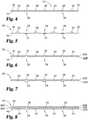
- FIG. 4 shown is another illustrative embodiment of a graft 20, where the electrodes are located on an outer surface 34 of the graft body 22.
- Fig. 4 provides a cross-sectional view of this embodiment of the graft layout of Fig. 1 , taken along line 2-2 and viewed in the direction of the arrows.
- Cathodes 24 and anodes 26 are bonded or otherwise attached to the same outer surface 34 of graft body 22 in this embodiment. Segments of outer surface 34 separate the cathodes 24 and anodes 26.
- Impregnation of graft body 22 with a conductive fluid provides electrical communication between cathodes 24 and anodes 26, causing electric current flow between cathodes 24 and anodes 26 that can serve to electrostimulate tissue development within graft body 22 and adjacent graft body 22.
- surface 36 opposite surface 34 is free of any cathodes 24 or anodes 26.
- Fig. 5 Shown in Fig. 5 is another illustrative embodiment of a graft 20, where the electrodes are located on surfaces of the graft body 22, with the cathodes 24 located on a first outer surface 34 and the anodes 26 located on a second outer surface 36 opposite the first surface.
- Fig. 5 provides a cross-sectional view of this embodiment of the graft layout of Fig. 1 , taken along line 2-2 and viewed in the direction of the arrows.
- a thickness of the graft body 22 separates the cathodes 24 and anodes 26. In this manner, the thickness of the graft body 22 provides a barrier against any risk of direct contact of cathodes 24 and anodes 26 with each other when graft 20 is implanted.
- Such direct contact would interrupt a desired communication of current through conductive fluid, for example body fluid, within and surrounding graft body 22 upon implantation.
- the cathodes 24 and anodes 26 are not aligned (or not in registry) with one another through the thickness of the graft body 22, establishing a shortest distance between cathodes 24 and anodes 26 along a line that travels diagonally through the thickness of graft body 22. It is contemplated in other, related embodiments, that the cathodes 24 and anodes 26 can be partially or completely aligned with one another through the thickness of the graft body 22.
- combinations of partially, completely and/or non-aligned electrodes through the thickness of the graft body 22 can be used.
- the positions of the cathodes 24 and anodes 26 can be interchanged with one another, or combinations of cathodes 24 on both sides 30 and 32 and/or of anodes 26 on both sides 30 and 32 can be included.
- Fig. 6 shows another illustrative embodiment of a graft 20, in which some electrodes are located within the graft body 22 and some electrodes are located on an outer surface at one side 30 of the graft body 22.
- Fig. 6 provides a cross-sectional view of this embodiment of the graft layout of Fig. 1 , taken along line 2-2 and viewed in the direction of the arrows.
- a partial thickness of the graft body 22 separates the cathodes 24 and anodes 26.
- this thickness of the graft body 22 provides a barrier against any risk of direct contact of cathodes 24 and anodes 26 with each other when graft 20 is implanted.
- the cathodes 24 and anodes 26 are not aligned (or not in registry) with one another through the thickness of the graft body 22, establishing a shortest distance between cathodes 24 and anodes 26 along a line that travels diagonally through the partial thickness of graft body 22. It is contemplated in other, related embodiments, that the cathodes 24 and anodes 26 can be partially or completely aligned with one another through the thickness of the graft body 22.
- combinations of partially, completely and/or non-aligned electrodes through the partial thickness of the graft body 22 can be used.
- the positions of the cathodes 24 and anodes 26 can be interchanged with one another, or combinations of outer and inner cathodes 24 and/or of outer and inner anodes 26 can be included.
- Fig. 7 shown is an illustrative embodiment of a graft 20, in which some electrodes are located within graft body 22, some electrodes are located on a first outer surface at one side 30 of the graft body 22, and some electrodes are located on a second outer surface at another side 32 of the graft body 22.
- Fig. 7 provides a cross-sectional view of this embodiment of the graft layout of Fig. 1 , taken along line 2-2 and viewed in the direction of the arrows. In this embodiment, as in the embodiment of Fig.
- a partial thickness of the graft body 22 separates the cathodes 24, which are located within graft body 22, and anodes 26, which are located on opposite outer surfaces 30 and 32 of graft body 22.
- This thickness of the graft body 22 provides a barrier against any risk of direct contact of cathodes 24 and anodes 26 with each other when graft 20 is implanted. As before, such direct contact would interrupt a desired communication of current through conductive fluid, for example body fluid, within and surrounding graft body 22 upon implantation. Also in the embodiment of Fig.
- the cathodes 24 and anodes 26 are not aligned (or not in registry) with one another through the thickness of the graft body 22, establishing a shortest distance between cathodes 24 and anodes 26 along a line that travels diagonally through the partial thickness of graft body 22.
- the anodes 26 occurring on opposite sides 30 and 32 of the graft body 22 are aligned (or in registry with) one another through the thickness of the graft body 22. It is contemplated in other, related embodiments, that the cathodes 24 and anodes 26 can be partially or completely aligned with one another through the thickness of the graft body 22.
- combinations of partially, completely and/or non-aligned electrodes through the partial thickness of the graft body 22 can be used.
- the positions of the cathodes 24 and anodes 26 can be interchanged with one another, or combinations of outer and inner cathodes 24 and/or of outer and inner anodes 26 can be included.
- Fig. 8 Shown in Fig. 8 is still another illustrative embodiment of a graft 20, in which electrodes are located within the graft body 22 at different levels through the thickness of the graft body between a first outer surface 38 and a second outer surface 40 opposite the first outer surface 38.
- Fig. 8 provides a cross-sectional view of this embodiment of the graft layout of Fig. 1 , taken along line 2-2 and viewed in the direction of the arrows.
- a partial thickness of the graft body 22 separates the cathodes 24, which are located within graft body 22, and anodes 26, which are also located within the graft body.
- This thickness of the graft body 22 provides a barrier against any risk of direct contact of cathodes 24 and anodes 26 with each other when graft 20 is implanted. As before, such direct contact would interrupt a desired communication of current through conductive fluid, for example body fluid, within and surrounding graft body 22 upon implantation. Also in the embodiment of Fig. 8 , the cathodes 24 and anodes 26 are not aligned (or not in registry) with one another through the thickness of the graft body 22, establishing a shortest distance between cathodes 24 and anodes 26 along a line that travels diagonally through the partial thickness of graft body 22.
- the cathodes 24 and anodes 26 can be partially or completely aligned with one another through the thickness of the graft body 22. In still other embodiments, combinations of partially, completely and/or non-aligned electrodes through the partial thickness of the graft body 22 can be used. Also, in any of these embodiments, the positions of the cathodes 24 and anodes 26 can be interchanged with one another, or combinations cathodes 24 and/or anodes 26 at different levels within the thickness of the graft body 22 can be included.
- layer 8 is a laminate including layer(s) 22A and layer(s) 22B as in some of the embodiments discussed above, as well as layer(s) 22D. This provides a further laminate interface 22D at which some of the electrodes (e.g. cathodes 24) can be positioned.
- the electrodes e.g. cathodes 24
- Electrostimulative grafts of the present disclosure can have any suitable three-dimensional form.
- grafts discussed in conjunction with Figs. 1-8 above can have a non-tubular form, such as a sheet form.
- electrostimulative grafts of the present disclosure have at least a portion that forms a tube, and potentially are tubular grafts.
- partially or completely tubular grafts can have electrode positioning on surface(s) and/or within thicknesses of the grafts that are the same as those discussed in conjunction with Figs. 1-8 , in certain embodiments.
- Such grafts may or may not have thru-holes 28 as depicted in Figs. 1-8 .
- such grafts may have electrode positioning so that the galvanic couple provides a current that extends axially (along the long axis of) the tube or tube portion of the graft.
- Fig. 9 provides a perspective view of graft 50
- Fig. 10 provides a cross-sectional view taken along the longitudinal axis of graft 50 of Fig. 9
- Graft 50 includes a tubular graft wall 52 defining an inner lumen 54.
- the graft wall 52 is a laminate, with a first layer or layers 52A of graft material occurring toward an outer surface 56 of graft wall 52 and a second layer or layers 52B of graft material occurring toward a luminal surface 58 of the graft wall opposite the outer surface 56.
- a laminate interface 52C occurs between layer(s) 52A and layer(s) 52B.
- a cathode 60 preferably in the form of a helical wire as shown
- an anode 62 also preferably in the form of a helical wire as shown, are captured between layer(s) 52A and layer(s) 52B at the interface 52C.
- Interface 52C is preferably a bonded interface. Suitable bonding techniques are discussed hereinbelow.
- the cathode 60 occurs to a first longitudinal side of the graft 50 and the anode 62 occurs to a second longitudinal side of the graft 50, with an intermediate segment 64 of the graft wall 52 separating the central-most end of the cathode 60 from the central-most end of the anode 62 along the length of the tubular graft wall 52.
- the galvanic couple will generate current that travels axially along the tubular graft.
- tubular grafts such as those depicted in Figs. 9 and 10 can in some modes be used as nerve cuffs or wraps to stimulate the growth of nerve tissue.
- Fig. 11 provides a perspective view of graft 70
- Fig. 12 provides a cross-sectional view taken along the longitudinal axis of graft 70 of Fig. 19.
- Graft 70 includes a tubular graft wall 72 defining an inner lumen 74.
- the graft wall 72 is a laminate, with a first layer or layers 72A of graft material occurring toward an outer surface 76 of graft wall 72 and a second layer or layers 72B of graft material occurring toward a luminal surface 78 of the graft wall opposite the outer surface 76.
- a laminate interface 72C occurs between layer(s) 72A and layer(s) 72B.
- a cathode 80 preferably in the form of a helical wire as shown
- an anode 82 also preferably in the form of a helical wire as shown, are captured between layer(s) 72A and layer(s) 72B at the interface 72C.
- Interface 72C is preferably a bonded interface, with suitable bonding techniques discussed hereinbelow.
- the cathode 80 and the anode 82 are provided as overlapped helical wires positioned so that the turns of the wires of cathode 80 and the turns of the wires of anode 82 occur alternately, but do not directly contact one another, along the length of the graft body 72.
- tubular grafts such as those depicted in Figs. 11 and 12 can in some modes be used as nerve cuffs or wraps to stimulate the growth of nerve tissue.
- grafts shown in Figs. 9-12 are shown as completely circumferential tubes, it is also contemplated that similar grafts can be prepared having a generally tubular shape but including a longitudinal slit extending the length of the grafts. Such split grafts may be more readily implanted over longitudinally-extending structures such as vessels or nerves, since a side-mount approach may be used in which the patient tissue structure is passed through the longitudinal slit into the lumen region of the graft.
- the graft material of the electrostimulative grafts herein will include one or more intact segments of decellularized collagenous tissue membrane.
- Suitable materials for incorporation in any of the embodiments herein can be provided by membranous collagenous extracellular matrix (ECM) materials.
- ECM extracellular matrix
- suitable membranous ECM materials include as examples those comprising submucosa, renal capsule membrane, dermal collagen, dura mater, pericardium, fascia lata, serosa, subserous fascia, amnion, peritoneum or basement membrane layers, including liver basement membrane.
- Suitable submucosa materials for these purposes include, for instance, intestinal submucosa including small intestinal submucosa, stomach submucosa, urinary bladder submucosa, and uterine submucosa.
- ECM materials can be characterized as membranous tissue layers or sheets harvested from a source tissue and decellularized. These membranous tissue sheets can have a porous matrix comprised of a network of collagen fibers, wherein the network of collagen fibers preferably retains an inherent network structure from the source tissue.
- collagenous matrices comprising submucosa (potentially along with other associated tissues) useful in the present invention can be obtained by harvesting such tissue sources and delaminating the submucosa-containing matrix from smooth muscle layers, mucosal layers, and/or other layers occurring in the tissue source, and decellularizing the matrix before or after such delaminating .
- tissue sources and delaminating the submucosa-containing matrix from smooth muscle layers, mucosal layers, and/or other layers occurring in the tissue source, and decellularizing the matrix before or after such delaminating .
- Submucosa-containing or other ECM tissue when used in the invention, is preferably highly purified, for example, as described in U.S. Patent No. 6,206,931 to Cook et al.
- preferred ECM material will exhibit an endotoxin level of less than about 12 endotoxin units (EU) per gram, more preferably less than about 5 EU per gram, and most preferably less than about 1 EU per gram.
- EU endotoxin units
- the submucosa or other ECM material may have a bioburden of less than about 1 colony forming units (CFU) per gram, more preferably less than about 0.5 CFU per gram.
- CFU colony forming units
- Fungus levels are desirably similarly low, for example less than about 1 CFU per gram, more preferably less than about 0.5 CFU per gram.
- Nucleic acid levels are preferably less than about 5 ⁇ g/mg, more preferably less than about 2 ⁇ g/mg, and virus levels are preferably less than about 50 plaque forming units (PFU) per gram, more preferably less than about 5 PFU per gram.
- PFU plaque forming units
- Submucosa-containing or other membranous ECM tissue material may retain one or more growth factors native to the source tissue for the tissue material, such as but not limited to basic fibroblast growth factor (FGF-2), transforming growth factor beta (TGF-beta), epidermal growth factor (EGF), cartilage derived growth factor (CDGF), and/or platelet derived growth factor (PDGF).
- FGF-2 basic fibroblast growth factor
- TGF-beta transforming growth factor beta
- EGF epidermal growth factor
- CDGF cartilage derived growth factor
- PDGF platelet derived growth factor
- submucosa or other ECM materials when used in embodiments herein may retain other bioactive agents native to the source tissue, such as but not limited to proteins, glycoproteins, proteoglycans, and glycosaminoglycans.
- ECM materials may include native heparin, native heparin sulfate, native hyaluronic acid, native fibronectin, native cytokines, and the like.
- a submucosa or other ECM material may retain one or more native bioactive components from the source tissue that induce, directly or indirectly, a cellular response such as a change in cell morphology, proliferation, growth, protein or gene expression.
- these or other non-collagen substances retained from the source tissue can affect the conductivity of the graft material, especially when wetted (e.g. after implant by body fluid) and especially when the retained substances are ionically charged, and thereby affect the electrostimulative properties of the graft.
- Submucosa-containing or other ECM materials can be derived from any suitable organ or other tissue source, usually sources containing connective tissues.
- the ECM materials processed for use in the invention will typically be membranous tissue sheets that include abundant collagen, most commonly being constituted at least about 80% by weight collagen on a dry weight basis.
- Such naturally-derived ECM materials will for the most part include collagen fibers that are non-randomly oriented, for instance occurring as generally uniaxial or multi-axial but regularly oriented fibers.
- the ECM material can retain these factors interspersed as solids between, upon and/or within the collagen fibers.
- Particularly desirable naturally-derived ECM materials for use in the invention will include significant amounts of such interspersed, non-collagenous solids that are readily ascertainable under light microscopic examination with appropriate staining.
- non-collagenous solids can constitute a significant percentage of the dry weight of the ECM material in certain inventive embodiments, for example at least about 1%, at least about 3%, and at least about 5 % by weight in various embodiments of the invention.
- a submucosa-containing or other ECM material used in embodiments herein may also exhibit an angiogenic character and thus be effective to induce angiogenesis in a host engrafted with the material.
- angiogenesis is the process through which the body makes new blood vessels to generate increased blood supply to tissues.
- angiogenic materials when contacted with host tissues, promote or encourage the formation of new blood vessels into the materials.
- Methods for measuring in vivo angiogenesis in response to biomaterial implantation have recently been developed. For example, one such method uses a subcutaneous implant model to determine the angiogenic character of a material. See, C. Heeschen et al., Nature Medicine 7 (2001), No. 7, 833-839 . When combined with a fluorescence microangiography technique, this model can provide both quantitative and qualitative measures of angiogenesis into biomaterials. C. Johnson et al., Circulation Research 94 (2004), No. 2, 262-268 .
- non-native bioactive components such as those synthetically produced by recombinant technology or other methods (e.g., genetic material such as DNA), may be incorporated into the ECM material.
- These non-native bioactive components may be naturally-derived or recombinantly produced proteins that correspond to those natively occurring in an ECM tissue, but perhaps of a different species.
- These non-native bioactive components may also be drug substances.
- Illustrative drug substances that may be added to materials include, for example, anti-clotting agents, e.g.
- the non-native bioactive component(s) can also be cells, including for example stem cells, which can be attached to and/or cultured on the ECM of electrostimulative grafts prior to implantation if desired.
- non-native bioactive components can be incorporated into and/or onto ECM material in any suitable manner, for example, by surface treatment (e.g., spraying) and/or impregnation (e.g., soaking), just to name a few.
- these substances may be applied to the ECM material in a premanufacturing step, immediately prior to the procedure (e.g., by soaking the electrostimulative graft in a solution containing a suitable antibiotic such as cefazolin), or during or after engraftment of the electrostimulative graft in the patient.
- the electrostimulative graft can include a laminate of two or more individual layers of membranous ECM material (e.g., 2 or more layers bonded together).
- the total thickness of such a construct can in some forms be more than about 400 microns, or more than about 600 microns, or more than about 800 microns, or more than about 1,000 microns, or more than about 1,200 microns, or more than about 1,500 microns but typically less than about 2,000 microns.
- the thickness of such a construct is in the range of about 200 microns to about 4,000 microns.
- 2 to about 20 layers of membranous ECM tissue material are bonded in a laminate construct of an electrostimulative graft.
- Suitable bonding techniques in forming laminate constructs include chemical crosslinking and techniques other than chemical crosslinking, or combinations thereof.
- Techniques other than chemical cross-linking include vacuum pressing, lyophilization, or other dehydrothermal bonding conditions and/or the use of an adhesive, glue or other bonding agents.
- Suitable bonding agents may include, for example, collagen gels or pastes, gelatin, fibrin glues, or other agents including reactive monomers or polymers, for example cyanoacrylate adhesives. Bonding by chemical crosslinking can achieved using chemical cross-linking agents, such as glutaraldehyde, formaldehyde, epoxides, genipin or derivatives thereof, carbodiimide compounds, polyepoxide compounds, or other similar agents.
- dehydration-induced bonding and chemical crosslinking is used in certain embodiments.
- an electrode or electrodes are to be located within a thickness of a graft, such electrode(s) can be positioned between layers to form the laminate prior to bonding the layers to one another.
- dehydration-induced bonding methods can be used to fuse and thereby laminate layers of membranous ECM materials together.
- multiple layers of the membranous ECM material are compressed under dehydrating conditions.
- dehydrating conditions can include any mechanical or environmental condition which promotes or induces the removal of water from the multi-layered medical material.
- at least one of the two surfaces compressing the matrix structure can be water permeable.
- Dehydration of the material can optionally be further enhanced by applying blotting material, heating the matrix structure or blowing air, or other inert gas, across the exterior of the compressing surfaces.
- Particularly useful methods of dehydration bonding the ECM layers to one another include lyophilization, e.g. freeze-drying or evaporative cooling conditions, vacuum pressing, oven drying and/or air drying.
- ECM materials for use in making electrostimulative grafts can be processed using methods that decrease the content of undesired components of the source tissue such as cells, nucleic acid, lipids and/or immunoglobulins such as IgA, while retaining substantial levels of desired components from the source tissue such as growth factor(s) (e.g. Fibroblast Growth Factor-2), proteoglycans and/or glycosaminoglycans (GAGs).
- growth factor(s) e.g. Fibroblast Growth Factor-2
- proteoglycans and/or glycosaminoglycans GAGs
- Such treatments can be performed with detergent, basic medium, liquid organic solvent, and/or disinfecting solution, for example as described in U.S. Patent No. 8,192,763 issued June 5, 2012 , the disclosure of which is specifically incorporated herein by reference in its entirety.
- porous graft material can include or be an extracellular matrix material as discussed above, in other embodiments the porous graft material can be or include a synthetic graft material, for example a synthetic polymeric graft material.
- synthetic polymeric or other graft materials can be biodegradable or non-biodegradable, and are preferably biodegradable.
- Suitable biodegradable polymers for these purposes include, for example, aliphatic polyesters, poly (amino acids), copoly (ether-esters), polyalkylenes oxalates, polyamides, tyrosine derived polycarbonates, poly (iminocarbonates), polyorthoesters, polyoxaesters, polyamidoesters, polyoxaesters containing amine groups, poly (anhydrides), polyphosphazenes, and combinations thereof.
- Biodegradable aliphatic polyesters include, but are not limited to, homopolymers and copolymers of lactide (which includes lactic acid, D-, L- and meso lactide), glycolide (including glycolic acid), epsilon-caprolactone, p-dioxanone (1,4-dioxan-2-one), trimethylene carbonate (1,3-dioxan-2-one), alkyl derivatives of trimethylene carbonate, and polymer blends thereof.
- lactide which includes lactic acid, D-, L- and meso lactide
- glycolide including glycolic acid
- epsilon-caprolactone p-dioxanone (1,4-dioxan-2-one
- trimethylene carbonate 1,3-dioxan-2-one
- alkyl derivatives of trimethylene carbonate and polymer blends thereof.
- These or other synthetic polymers can be molded, cast or otherwise processed to form a porous
- the porous graft matrix can be a laminate of layers as discussed hereinabove, or in other embodiments can be a unitary, continuous matrix.
- any suitable technique can be used to locate and embed the electrode(s) within the thickness. These include, for example, casting or molding the polymeric matrix forming material around the electrode(s) to be embedded within the porous graft material thickness.
- the porous graft matrix material is biodegradable.
- the porous graft matrix material whether being a naturally-derived material such as an ECM discussed above, or a synthetic polymeric material as discussed above, will be bioremodelable such that the graft matrix material is degraded as new tissue of the patient grows into the graft matrix material.
- the electrostimulative grafts can be completely biodegradable after implantation in a patient, with both the electrodes and the porous graft matrix material ultimately being completely degraded and eliminated from the site of implantation.
- Electrodes can be formed in any suitable fashion. As examples, they can be cut or stamped from sheets, printed (e.g. as with a conductive ink) or plated onto the graft material or another substrate material to be included in the graft. Further, individual electrodes can be monolithic structures, or can be stacks or laminates (e.g. of metal foil layers) or masses of directly contacting particles of the cathode or anode material (e.g. deposited particles that are captured at the interface of a laminate graft structure as discussed above). These and other arrangements are contemplated as being within the scope of the embodiments disclosed herein.
- the electrodes of the electrostimulative grafts can be generally rigid structures that hold their shape on implantation, can be resilient structures that flex upon being subjected to external force (e.g. forces experienced by patient movements after implant) and return to their original shape upon removal of the external force, or can be conformable by plastic deformation against patient soft tissue or patient hard tissue (e.g. bone) upon implantation.
- Materials selection and electrode geometries can be controlled to impart these or other desired physical properties to the electrodes. Combinations of electrodes with different physical properties, such as those discussed above, can also be used.
- some or all of the electrodes of the graft can be temporarily electrically insulated by an insulative biodegradable material, for example one that is impervious to body fluids.
- an electrically insulative biodegradable material can be used to coat and encapsulate the electrode(s).
- Fig. 13 provides a cross-sectional view of one such illustrative embodiment, in which the electrode 90 (which can for example serve as some or all of the cathode(s) 24, 60 or 80 and/or some or all of the anodes 26, 62 or 82 discussed hereinabove) has an encapsulating coating 92 of an insulative biodegradable material.
- the insulative biodegradable material degrades and allows body fluid contact with the electrode(s), providing electrical communication between anode(s) and cathode(s) of a galvanic structure.
- a delayed initiation of electrostimulation by one, more than one, or all of the galvanic couples provided by the electrostimulative graft can be provided.
- a plurality of galvanic couple structures can be provided on the graft, with some temporarily electrically insulated by biodegradable material, and some not.
- the initially non-isolated galvanic couple structures can provide electrostimulation over a first period of time after implantation, and the temporarily electrically isolated galvanic couple structures can provide electrostimulation over a second period of time occurring after the initiation of the first period of time (e.g. partially overlapping the first period of time or occurring after the first period of time).
- staged electrostimulation by differing galvanic couple structures can increase the overall period of electrostimulation provided by the graft after implantation and/or can provide electrostimulation that varies over time in a predetermined pattern.
- any suitable metals can be included in the galvanic couple or couples included in the electrostimulative grafts.
- the metals can be pure elemental metals or alloys.
- the metals are desirably biodegradable and desirably form biodegradable materials when subjected to the redox reactions that occur during operation of the galvanic couple to generate current.
- the metal of the cathode(s) and the metal of the anode(s) will have a standard electrode potential difference of at least about 0.05V, more preferably at least about 0.1V, and typically in the range of about 0.05V to about 3 V, more typically in the range of about 0.1 V to about 2.4 V.
- standard electrode potential is potential of an electrode composed of a substance in its standard state, in equilibrium with ions in their standard states compared to a hydrogen electrode.
- Desirable metal materials to be included in the cathode(s) and/or anode(s) include, for example, biodegradable metals that are or include iron, magnesium, and/or zinc.
- the electrostimulative grafts will include biodegradable metals for the cathode(s) and anode(s) as set forth in Table 1 below: Table 1 Cathode Anode Standard Potential Difference Iron or iron alloy Magnesium or magnesium alloy About 0.80-2.40 V Iron or iron alloy Zinc or zinc alloy About 0.40-0.80 V Zinc or zinc alloy Magnesium or magnesium alloy About 0.60-1.70 V
- the characteristic intensity, spacing and general pattern of the electrical current generated in the electrostimulative graft will be dependent on several factors, including for example the shape of the graft, the size of the graft, the selected anode and cathode materials, the spacing of anode and cathode materials from one another, and the electrical properties of the graft material separating the anode and cathode materials from one another. These parameters can be controlled in the design of an electrostimulative graft to treat a given condition in a patient.
- the cathode(s) and anode(s) of the electrostimulative grafts will be spaced from one another on the graft material by a distance of at least about 1 mm, or at least about 2mm, and typically in the range of about 1mm to about 20mm, and more typically in the range of about 2mm to about 15mm.
- multiple anodes and cathodes are included on the electrostimulative graft, they may be included in a regular or irregular pattern.
- a given cathode may be spaced equidistantly from multiple anodes and thus may participate in a number of generally equivalent galvanic couples, and vice versa (see e.g. the electrode patterns of the embodiments of Figs. 1-8 ).
- the electrostimulative graft will include at least one, and potentially multiple, galvanic couple structures that, when implanted in the patient or when saturated with physiologic saline (a 0.9% weight/volume solution of sodium chloride in water), will generate a current between the anode and cathode of at least about 0.05 ⁇ A, and typically in the range of about 5 ⁇ A to about 500 mA, and/or a current density between the anode and cathode of at least about 1 ⁇ A/mm 2 , and typically in the range of about 5 ⁇ A/mm 2 to about 500 ⁇ A/mm 2 .
- physiologic saline a 0.9% weight/volume solution of sodium chloride in water
- the electrostimulative graft will include at least one, and potentially multiple, galvanic couple structures that, when implanted in the patient, will generate a voltage potential between the anode and cathode of at least about 0.05 V, and typically in the range of about 0.1 V to 2.40 V, and/or a voltage field strength between the anode and cathode of at least about 10 mV/mm, and typically in the range of about 50 mV/mm to about 1000 mV/mm.
- the current, current density, voltage potential, or voltage field strength may vary over time after implantation according to one or more factors, including for example tissue formation in and around the implanted graft, biodegradation of implanted graft material occurring between the anode(s) and cathode(s), and galvanic degradation and/or biodegradation of the electrode materials.
- the electrostimulative graft will be capable of generating the above-mentioned currents and/or the above-mentioned current densities and/or the above-mentioned voltage potentials and/or the above mentioned voltage field strengths over a period of at least about 6 hours, or at least about 1 day, or at least about 7 days, and in some forms in the range of about 1 day to about 180 days.
- the graft material of the electrostimulative graft in typical embodiments, is generally electrically non-conductive unless wetted with a conductive liquid medium, for example an ion-containing liquid medium such as saline or body fluid.
- a conductive liquid medium for example an ion-containing liquid medium such as saline or body fluid.
- the electrostimulative graft is desirably packaged in a dry condition (e.g. containing less than 10% moisture) within a medical package such as a pouch, foil or tray to prevent appreciable electrical communication between the cathode(s) and anode(s) of the electrostimulative graft during storage.
- the medical package will in some embodiments be moisture-resistant for these purposes.
- the electrostimulative graft after removal from the medical package, can be implanted in a patient whereupon the graft material becomes wetted with body fluid to establish electrical communication between the cathode(s) and anode(s) and thereby activate the galvanic couple(s) of the graft, or can be wetted with an ion-containing fluid such a physiologic saline or blood or a blood fraction (e.g. autologous to the patient) by a physician or other care provider to activate the galvanic couple(s) prior to implantation in the patient.
- an ion-containing fluid such as a physiologic saline or blood or a blood fraction (e.g. autologous to the patient) by a physician or other care provider to activate the galvanic couple(s) prior to implantation in the patient.
- the wetting of the graft material prior to or upon implantation in the patient will render the graft material more supple and conformable to patient tissue.
- the electrostimulative grafts disclosed herein can be terminally sterilized (including within medical packages as discussed above) using conventional techniques.
- the electrostimulative grafts can be terminally sterilized using ethylene oxide and/or using radiation such as E-beam or gas plasma (e.g. Sterrad) processing.
- Electrostimulative grafts of the present disclosure can be used in the treatment of a wide variety of defects of diseased conditions of soft or hard (e.g. bone) tissues in human or non-human animal (veterinary) patients.
- the electrostimulation generated by the galvanic couple structures upon implantation will impact the development of patient tissue within and/or around the implanted electrostimulative graft.
- the electrostimulative graft can be implanted alone in some applications. In other applications, the electrostimulative graft can be implanted along with a separate, secondary implant, for example a secondary porous graft material receptive to tissue ingrowth (e.g.
- the electrostimulative graft can then also electrostimulate regions occupied by the secondary porous graft material or other implant, to facilitate tissue development and/or other tissue regeneration responses within the secondary porous graft material or other implant.
- patient tissue growth can be stimulated in both the secondary porous graft material and in a porous graft material of the electrostimulative implant.
- the electrostimulative grafts herein can be provided in multiple (e.g. two, or two or more) discrete graft structures, for example with one (or more) graft structures having attached thereto the cathode(s) of a galvanic couple structure and one (or more) separate graft structures having attached thereto the anode(s) of the galvanic couple structure.
- the separate graft structures can then be implanted in conjunction with one another to position the cathode(s) and anode(s) in the galvanic couple structure.
- the separate graft structures will have amounts of the porous graft material that can be overlapped with one another between the cathode(s) and anode(s) upon implantation, and the galvanic couple(s) formed on implantation can generate current through and electrostimulate tissue growth into the region between the cathode(s) and anode(s), including into the overlapped amounts of porous graft matrix material.
- Such separate graft structures in these multi-part grafts can be packaged together (e.g. in packaging as discussed below) to provide a kit with which the physician or other care provider can prepare the electrostimulative graft prior to or upon implantation in the patient.
- the electrostimulative grafts will be used in the repair of nerve tissue in patients.
- a tubular electrostimulative graft for example as depicted in Figs. 9-10 or Figs. 11-12 , can be used as a nerve cuff in the repair of a severed nerve, such as a severed peripheral nerve.
- the end regions of the severed nerve can be inserted into the lumen of the tubular graft, and the electrostimulation provided by the graft can facilitate axonal growth and functional healing of the severed nerve. It is known that axonal growth occurs from the proximal to the distal stump of severed peripheral nerves.
- axonal growth occurs toward the cathode during electrostimulation.
- a cathode-containing end of a tubular or other electrostimulative graft herein e.g. the tubular graft depicted in Figs. 9-10
- an anode-containing end of an electrostimulative graft is implanted toward the proximal stump, such that the electrostimulation provided by the graft further facilitates axonal growth toward the distal stump and toward the cathode.
- a secondary porous graft material receptive to tissue ingrowth for example a decellularized nerve tissue graft
- a secondary porous graft material receptive to tissue ingrowth can be positioned between the proximal and distal stumps, and partially or completely surrounded by the electrostimulative graft.
- the electrostimulation provided by the electrostimulative graft can facilitate axonal growth through the secondary porous graft material.
- electrostimulation can facilitate wound healing in soft tissue.
- electrostimulative grafts can be used in the treatment of topical wounds, for example chronic ulcers, or in body wall repair such as hernia repair.
Claims (15)
- Elektrostimulatives Transplantatprodukt mit eigener Leistungsversorgung (20) zum Behandeln eines Patienten, umfassend:ein poröses Transplantatmatrixmaterial, aufnahmefähig zum Einwachsen von neuem Gewebe, wenn es in den Patienten implantiert wird; undeine galvanische Kopplungsstruktur, angebracht an das poröse Matrixmaterial und enthaltend eine Kathode (24), bestehend aus einem ersten Metall, beabstandet von einer Anode (26), bestehend aus einem zweiten Metall, wobei das erste Metall von dem zweiten Metall verschieden ist, und wobei vorzugsweise das erste Metall ein bioabbaubares Metall ist und das zweite Metall ein bioabbaubares Metall ist;wobei die galvanische Kopplungsstruktur funktionsfähig ist, elektrischen Strom in einem Weg zwischen der Anode und der Kathode zu erzeugen, wobei der Weg sich durch Mengen des zwischen der Anode und der Kathode positionierten porösen Matrixmaterials erstreckt.
- Transplantatprodukt (20) nach Anspruch 1, wobei:das poröse Transplantatmatrixmaterial mindestens teilweise in der Form eines Schlauchs ist; undder Weg sich in einer axialen Richtung entlang des Schlauchs erstreckt.
- Transplantatprodukt (20) nach Anspruch 1 oder 2, umfassend:eine Laminatstruktur, enthaltend eine Vielzahl von Folien (22A, 22B) des porösen Transplantatmatrixmaterials, die aneinander laminiert sind;wobei die Kathode (24) innerhalb der Laminatstruktur zwischen aneinander angrenzenden Folien der Vielzahl von Folien aufgenommen ist, wobei vorzugsweise das erste Metall ein bioabbaubares Metall ist; undwobei die Anode (26) innerhalb der Laminatstruktur zwischen aneinander angrenzenden Folien der Vielzahl von Folien aufgenommen ist, wobei vorzugsweise das zweite Metall ein bioabbaubares Metall ist.
- Transplantatprodukt (20) nach einem der vorstehenden Ansprüche, wobei:a) das poröse Transplantatmatrixmaterial Kollagen umfasst; und/oderb) wobei das poröse Transplantatmatrixmaterial eine oder mehrere Folien von dezellularisiertem membranartigem Gewebe umfasst, wobei vorzugsweise die Folien von dezellularisiertem membranartigem Gewebe einen oder mehrere native Wachstumsfaktoren aus einem Ursprungsgewebe für die Folien von membranartigem Gewebe zurückbehalten; und/oderc) wobei das poröse Transplantatmatrixmaterial dezellularisiertes Gewebe umfasst, ausgewählt aus submukösem Gewebe, Hautgewebe, Herzbeutelgewebe, Amniongewebe, Bauchfellgewebe oder Fasziengewebe.
- Transplantatprodukt (20) nach einem der vorstehenden Ansprüche, wobeia) das erste bioabbaubare Metall und das zweite bioabbaubare Metall eine elektrische Potenzialdifferenz von mindestens etwa 0,05 V aufweisen; und vorzugsweise im Bereich von etwa 0,05 V bis etwa 3 V, und/oderb) das erste bioabbaubare Metall Zink, Magnesium oder Eisen umfasst.
- Transplantatprodukt (20) nach einem der vorstehenden Ansprüche, wobei a) die galvanische Kopplungsstruktur einen elektrischen Strom zwischen der Kathode (24) und der Anode (26) im Bereich von etwa 5 µA bis etwa 500 mA erzeugt, wenn das Transplantat in physiologischer Kochsalzlösung gesättigt ist; und/oder b) die galvanische Kopplung eine Anode (26) und eine Kathode (24) mit einer standardmäßigen Elektrodenpotenzialdifferenz von mindestens etwa 0,05 V aufweist.
- Transplantatprodukt (20) nach einem der vorstehenden Ansprüche, wobei die Anode (26) und die Kathode (24) dimensioniert und konfiguriert sind, um innerhalb von etwa 180 Tagen nach der Implantation des Gewebetransplantats in einen Patienten abgebaut zu werden.
- Transplantatprodukt (20) nach einem der vorstehenden Ansprüche, wobei die Kathode (24) ist: a) beabstandet von der Anode (26) um eine Distanz von mindestens 1 mm; oder b) beabstandet um eine Distanz von etwa 1 mm bis etwa 20 mm von der Anode (26).
- Transplantatprodukt (20) nach einem der vorstehenden Ansprüche, wobei die Kathode (24) eine helixartige Form aufweist und/oder wobei die Anode (26) eine helixartige Form aufweist; wobei wahlweise die Anode und die Kathode beide eine helixartige Form aufweisen und wobei helixartige Windungen der Anode zwischen helixartigen Windungen der Kathode positioniert sind und sich in einer im Allgemeinen parallelen Weise dazu erstrecken.
- Transplantatprodukt (20) nach einem der vorstehenden Ansprüche, wobei das poröse Transplantatmatrixmaterial bioabbaubar ist und/oder wobei das poröse Transplantatmatrixmaterial bioremodellierbar ist.
- Transplantatprodukt (20) nach einem der vorstehenden Ansprüche, wobei mindestens eine der Anode (26) und der Kathode (24) durch ein bioabbaubares isolierendes Polymer elektrisch isoliert ist, wobei vorzugsweise sowohl die Anode als auch die Kathode durch ein bioabbaubares isolierendes Polymer elektrisch isoliert sind.
- Transplantatprodukt (20) nach einem der vorstehenden Ansprüche, umfassend eine Vielzahl der galvanischen Kopplungsstrukturen.
- Transplantatprodukt (20) nach einem der vorstehenden Ansprüche, wobei die galvanische Kopplung enthält:(i) eine Kathode (24), umfassend Eisen oder eine Eisenlegierung, und eine Anode (26), umfassend Magnesium oder eine Magnesiumlegierung; oder(ii) eine Kathode (24), umfassend Eisen oder eine Eisenlegierung, und eine Anode (26), umfassend Zink oder eine Zinklegierung; oder(iii) eine Kathode (24), umfassend Zink oder eine Zinklegierung, und eine Anode (26), umfassend Magnesium oder eine Magnesiumlegierung.
- Transplantatprodukt (20) nach einem der vorstehenden Ansprüche, steril verschlossen in medizinischer Verpackung, wobei vorzugsweise die medizinische Verpackung eine feuchtigkeitsbeständige Verpackung ist.
- Transplantatprodukt (20) nach Anspruch 14, in trockenem Zustand in der medizinischen Verpackung.
Applications Claiming Priority (1)
| Application Number | Priority Date | Filing Date | Title |
|---|---|---|---|
| US201662393001P | 2016-09-10 | 2016-09-10 |
Publications (2)
| Publication Number | Publication Date |
|---|---|
| EP3308829A1 EP3308829A1 (de) | 2018-04-18 |
| EP3308829B1 true EP3308829B1 (de) | 2020-04-29 |
Family
ID=60582362
Family Applications (1)
| Application Number | Title | Priority Date | Filing Date |
|---|---|---|---|
| EP17190216.6A Active EP3308829B1 (de) | 2016-09-10 | 2017-09-08 | Elektrostimulative transplantatprodukte |
Country Status (2)
| Country | Link |
|---|---|
| US (1) | US20180071526A1 (de) |
| EP (1) | EP3308829B1 (de) |
Families Citing this family (4)
| Publication number | Priority date | Publication date | Assignee | Title |
|---|---|---|---|---|
| CA3096883A1 (en) * | 2018-04-12 | 2019-10-17 | Axogen Corporation | Tissue grafts with pre-made attachment points |
| CN109125924A (zh) * | 2018-08-14 | 2019-01-04 | 上海白衣缘生物工程有限公司 | 一种生物套在电子器械心脏植入方面的应用 |
| CN109125922A (zh) * | 2018-08-14 | 2019-01-04 | 上海白衣缘生物工程有限公司 | 一种生物套在神经刺激器植入方面的应用 |
| CN111281610B (zh) * | 2019-12-30 | 2023-08-18 | 雅博尼西医疗科技(苏州)有限公司 | 多孔性结构和基底的连接结构 |
Family Cites Families (13)
| Publication number | Priority date | Publication date | Assignee | Title |
|---|---|---|---|---|
| US4902508A (en) | 1988-07-11 | 1990-02-20 | Purdue Research Foundation | Tissue graft composition |
| US5554389A (en) | 1995-04-07 | 1996-09-10 | Purdue Research Foundation | Urinary bladder submucosa derived tissue graft |
| ES2306841T3 (es) | 1996-08-23 | 2008-11-16 | Cook Biotech, Inc. | Protesis para injertos con base de colageno. |
| EP0946186B1 (de) | 1996-12-10 | 2003-03-26 | Purdue Research Foundation | Gewebetransplantat aus der magensubmukosa |
| US5993844A (en) | 1997-05-08 | 1999-11-30 | Organogenesis, Inc. | Chemical treatment, without detergents or enzymes, of tissue to form an acellular, collagenous matrix |
| US6312474B1 (en) * | 1999-09-15 | 2001-11-06 | Bio-Vascular, Inc. | Resorbable implant materials |
| CN101616698A (zh) | 2006-10-23 | 2009-12-30 | 库克生物科技公司 | 组分特性增强的处理的ecm材料 |
| WO2008122595A2 (en) * | 2007-04-05 | 2008-10-16 | Cinvention Ag | Biodegradable therapeutic implant for bone or cartilage repair |
| AU2009267181A1 (en) | 2008-07-01 | 2010-01-07 | Cook Biotech Incorporated | Isolated extracellular matrix material including subserous fascia |
| CA2780537A1 (en) * | 2009-11-13 | 2011-05-19 | Johnson & Johnson Consumer Companies, Inc. | Galvanic skin treatment device |
| AU2014370031A1 (en) * | 2013-12-27 | 2016-07-21 | Neograft Technologies, Inc. | Artificial graft devices and related systems and methods |
| EP3838332A1 (de) * | 2014-06-03 | 2021-06-23 | Vomaris Innovations, Inc. | Vorrichtung zur hautbehandlung |
| GB2551171B (en) * | 2016-06-08 | 2021-09-22 | Feeligreen Sa | Skin treatment device and method for producing said skin treatment device |
-
2017
- 2017-09-08 US US15/698,798 patent/US20180071526A1/en active Pending
- 2017-09-08 EP EP17190216.6A patent/EP3308829B1/de active Active
Non-Patent Citations (1)
| Title |
|---|
| None * |
Also Published As
| Publication number | Publication date |
|---|---|
| US20180071526A1 (en) | 2018-03-15 |
| EP3308829A1 (de) | 2018-04-18 |
Similar Documents
| Publication | Publication Date | Title |
|---|---|---|
| EP3308829B1 (de) | Elektrostimulative transplantatprodukte | |
| US20180272136A1 (en) | Methods and systems for generating a tissue pocket in a patient | |
| EP2254607B1 (de) | Graft-materialien und verfahren für die stufenweise abgabe von biologischen wirkstoffen | |
| EP1545389B1 (de) | Gerät zur prävention von adhäsionen zwischen einem implantat und dem umgebenden gewebe | |
| DE69731553T2 (de) | Rohrförmiges transplantat aus gereinigter submukosa | |
| US8470356B2 (en) | Tissue augmentation devices and methods | |
| EP2326355B1 (de) | Verfahren zur herstellung eines azellulären matrixklebstoffs | |
| US20030133967A1 (en) | Multilayer collagen matrix for tissue reconstruction | |
| US20050187639A1 (en) | Soft tissue implants and anti-scarring agents | |
| US11311735B2 (en) | Implantable pouch with segmental lamination structure, and related methods of manufacture and use | |
| JP4840136B2 (ja) | 癒着防止用キット、癒着防止用キットの製造方法および癒着防止方法 | |
| US9254188B2 (en) | Kits, components and methods for tissue reconstruction | |
| US20100266654A1 (en) | Medical composition including an extracellular matrix particulate | |
| US20090142400A1 (en) | Analgesic coated medical product | |
| WO2010027612A2 (en) | Acellular matrix glue | |
| CN109528327A (zh) | 一种引导骨再生装置 | |
| Eap et al. | Nanostructured thick 3D nanofibrous scaffold can induce bone | |
| US10058631B2 (en) | Tonsillectomy sponge | |
| WO2007121281A2 (en) | System for conditioning surfaces in vivo | |
| IL196002A (en) | Collagen tubes | |
| RU220031U1 (ru) | Биологический чехол для имплантируемых электронных устройств | |
| RU218046U1 (ru) | Биологический чехол для имплантируемых электронных устройств на основе внеклеточного матрикса | |
| WO2018201116A1 (en) | Umbilical cord implantable cover and method of making | |
| EP3582818A1 (de) | Dezellularisierte implantathüllen |
Legal Events
| Date | Code | Title | Description |
|---|---|---|---|
| PUAI | Public reference made under article 153(3) epc to a published international application that has entered the european phase |
Free format text: ORIGINAL CODE: 0009012 |
|
| STAA | Information on the status of an ep patent application or granted ep patent |
Free format text: STATUS: THE APPLICATION HAS BEEN PUBLISHED |
|
| AK | Designated contracting states |
Kind code of ref document: A1 Designated state(s): AL AT BE BG CH CY CZ DE DK EE ES FI FR GB GR HR HU IE IS IT LI LT LU LV MC MK MT NL NO PL PT RO RS SE SI SK SM TR |
|
| AX | Request for extension of the european patent |
Extension state: BA ME |
|
| STAA | Information on the status of an ep patent application or granted ep patent |
Free format text: STATUS: REQUEST FOR EXAMINATION WAS MADE |
|
| 17P | Request for examination filed |
Effective date: 20181018 |
|
| RBV | Designated contracting states (corrected) |
Designated state(s): AL AT BE BG CH CY CZ DE DK EE ES FI FR GB GR HR HU IE IS IT LI LT LU LV MC MK MT NL NO PL PT RO RS SE SI SK SM TR |
|
| GRAP | Despatch of communication of intention to grant a patent |
Free format text: ORIGINAL CODE: EPIDOSNIGR1 |
|
| STAA | Information on the status of an ep patent application or granted ep patent |
Free format text: STATUS: GRANT OF PATENT IS INTENDED |
|
| RIC1 | Information provided on ipc code assigned before grant |
Ipc: A61L 27/24 20060101ALI20190617BHEP Ipc: A61L 27/36 20060101ALI20190617BHEP Ipc: A61L 27/50 20060101ALI20190617BHEP Ipc: A61B 17/00 20060101ALN20190617BHEP Ipc: A61F 2/30 20060101ALN20190617BHEP Ipc: A61N 1/05 20060101ALN20190617BHEP Ipc: A61L 27/56 20060101ALI20190617BHEP Ipc: A61F 2/02 20060101ALI20190617BHEP Ipc: A61L 27/58 20060101ALI20190617BHEP Ipc: A61F 2/28 20060101ALI20190617BHEP Ipc: A61B 17/11 20060101ALI20190617BHEP Ipc: A61F 2/04 20130101ALN20190617BHEP Ipc: A61L 27/00 20060101ALN20190617BHEP Ipc: A61N 1/20 20060101AFI20190617BHEP |
|
| INTG | Intention to grant announced |
Effective date: 20190716 |
|
| GRAS | Grant fee paid |
Free format text: ORIGINAL CODE: EPIDOSNIGR3 |
|
| GRAA | (expected) grant |
Free format text: ORIGINAL CODE: 0009210 |
|
| STAA | Information on the status of an ep patent application or granted ep patent |
Free format text: STATUS: THE PATENT HAS BEEN GRANTED |
|
| AK | Designated contracting states |
Kind code of ref document: B1 Designated state(s): AL AT BE BG CH CY CZ DE DK EE ES FI FR GB GR HR HU IE IS IT LI LT LU LV MC MK MT NL NO PL PT RO RS SE SI SK SM TR |
|
| REG | Reference to a national code |
Ref country code: GB Ref legal event code: FG4D |
|
| REG | Reference to a national code |
Ref country code: CH Ref legal event code: EP |
|
| REG | Reference to a national code |
Ref country code: AT Ref legal event code: REF Ref document number: 1262386 Country of ref document: AT Kind code of ref document: T Effective date: 20200515 |
|
| REG | Reference to a national code |
Ref country code: DE Ref legal event code: R096 Ref document number: 602017015566 Country of ref document: DE |
|
| REG | Reference to a national code |
Ref country code: IE Ref legal event code: FG4D |
|
| REG | Reference to a national code |
Ref country code: NL Ref legal event code: MP Effective date: 20200429 |
|
| REG | Reference to a national code |
Ref country code: LT Ref legal event code: MG4D |
|
| PG25 | Lapsed in a contracting state [announced via postgrant information from national office to epo] |
Ref country code: FI Free format text: LAPSE BECAUSE OF FAILURE TO SUBMIT A TRANSLATION OF THE DESCRIPTION OR TO PAY THE FEE WITHIN THE PRESCRIBED TIME-LIMIT Effective date: 20200429 Ref country code: LT Free format text: LAPSE BECAUSE OF FAILURE TO SUBMIT A TRANSLATION OF THE DESCRIPTION OR TO PAY THE FEE WITHIN THE PRESCRIBED TIME-LIMIT Effective date: 20200429 Ref country code: GR Free format text: LAPSE BECAUSE OF FAILURE TO SUBMIT A TRANSLATION OF THE DESCRIPTION OR TO PAY THE FEE WITHIN THE PRESCRIBED TIME-LIMIT Effective date: 20200730 Ref country code: PT Free format text: LAPSE BECAUSE OF FAILURE TO SUBMIT A TRANSLATION OF THE DESCRIPTION OR TO PAY THE FEE WITHIN THE PRESCRIBED TIME-LIMIT Effective date: 20200831 Ref country code: NO Free format text: LAPSE BECAUSE OF FAILURE TO SUBMIT A TRANSLATION OF THE DESCRIPTION OR TO PAY THE FEE WITHIN THE PRESCRIBED TIME-LIMIT Effective date: 20200729 Ref country code: IS Free format text: LAPSE BECAUSE OF FAILURE TO SUBMIT A TRANSLATION OF THE DESCRIPTION OR TO PAY THE FEE WITHIN THE PRESCRIBED TIME-LIMIT Effective date: 20200829 Ref country code: SE Free format text: LAPSE BECAUSE OF FAILURE TO SUBMIT A TRANSLATION OF THE DESCRIPTION OR TO PAY THE FEE WITHIN THE PRESCRIBED TIME-LIMIT Effective date: 20200429 |
|
| REG | Reference to a national code |
Ref country code: AT Ref legal event code: MK05 Ref document number: 1262386 Country of ref document: AT Kind code of ref document: T Effective date: 20200429 |
|
| PG25 | Lapsed in a contracting state [announced via postgrant information from national office to epo] |
Ref country code: RS Free format text: LAPSE BECAUSE OF FAILURE TO SUBMIT A TRANSLATION OF THE DESCRIPTION OR TO PAY THE FEE WITHIN THE PRESCRIBED TIME-LIMIT Effective date: 20200429 Ref country code: HR Free format text: LAPSE BECAUSE OF FAILURE TO SUBMIT A TRANSLATION OF THE DESCRIPTION OR TO PAY THE FEE WITHIN THE PRESCRIBED TIME-LIMIT Effective date: 20200429 Ref country code: BG Free format text: LAPSE BECAUSE OF FAILURE TO SUBMIT A TRANSLATION OF THE DESCRIPTION OR TO PAY THE FEE WITHIN THE PRESCRIBED TIME-LIMIT Effective date: 20200729 Ref country code: LV Free format text: LAPSE BECAUSE OF FAILURE TO SUBMIT A TRANSLATION OF THE DESCRIPTION OR TO PAY THE FEE WITHIN THE PRESCRIBED TIME-LIMIT Effective date: 20200429 |
|
| PG25 | Lapsed in a contracting state [announced via postgrant information from national office to epo] |
Ref country code: AL Free format text: LAPSE BECAUSE OF FAILURE TO SUBMIT A TRANSLATION OF THE DESCRIPTION OR TO PAY THE FEE WITHIN THE PRESCRIBED TIME-LIMIT Effective date: 20200429 Ref country code: NL Free format text: LAPSE BECAUSE OF FAILURE TO SUBMIT A TRANSLATION OF THE DESCRIPTION OR TO PAY THE FEE WITHIN THE PRESCRIBED TIME-LIMIT Effective date: 20200429 |
|
| PG25 | Lapsed in a contracting state [announced via postgrant information from national office to epo] |
Ref country code: ES Free format text: LAPSE BECAUSE OF FAILURE TO SUBMIT A TRANSLATION OF THE DESCRIPTION OR TO PAY THE FEE WITHIN THE PRESCRIBED TIME-LIMIT Effective date: 20200429 Ref country code: RO Free format text: LAPSE BECAUSE OF FAILURE TO SUBMIT A TRANSLATION OF THE DESCRIPTION OR TO PAY THE FEE WITHIN THE PRESCRIBED TIME-LIMIT Effective date: 20200429 Ref country code: AT Free format text: LAPSE BECAUSE OF FAILURE TO SUBMIT A TRANSLATION OF THE DESCRIPTION OR TO PAY THE FEE WITHIN THE PRESCRIBED TIME-LIMIT Effective date: 20200429 Ref country code: CZ Free format text: LAPSE BECAUSE OF FAILURE TO SUBMIT A TRANSLATION OF THE DESCRIPTION OR TO PAY THE FEE WITHIN THE PRESCRIBED TIME-LIMIT Effective date: 20200429 Ref country code: EE Free format text: LAPSE BECAUSE OF FAILURE TO SUBMIT A TRANSLATION OF THE DESCRIPTION OR TO PAY THE FEE WITHIN THE PRESCRIBED TIME-LIMIT Effective date: 20200429 Ref country code: SM Free format text: LAPSE BECAUSE OF FAILURE TO SUBMIT A TRANSLATION OF THE DESCRIPTION OR TO PAY THE FEE WITHIN THE PRESCRIBED TIME-LIMIT Effective date: 20200429 Ref country code: IT Free format text: LAPSE BECAUSE OF FAILURE TO SUBMIT A TRANSLATION OF THE DESCRIPTION OR TO PAY THE FEE WITHIN THE PRESCRIBED TIME-LIMIT Effective date: 20200429 Ref country code: DK Free format text: LAPSE BECAUSE OF FAILURE TO SUBMIT A TRANSLATION OF THE DESCRIPTION OR TO PAY THE FEE WITHIN THE PRESCRIBED TIME-LIMIT Effective date: 20200429 |
|
| REG | Reference to a national code |
Ref country code: DE Ref legal event code: R097 Ref document number: 602017015566 Country of ref document: DE |
|
| PG25 | Lapsed in a contracting state [announced via postgrant information from national office to epo] |
Ref country code: SK Free format text: LAPSE BECAUSE OF FAILURE TO SUBMIT A TRANSLATION OF THE DESCRIPTION OR TO PAY THE FEE WITHIN THE PRESCRIBED TIME-LIMIT Effective date: 20200429 Ref country code: PL Free format text: LAPSE BECAUSE OF FAILURE TO SUBMIT A TRANSLATION OF THE DESCRIPTION OR TO PAY THE FEE WITHIN THE PRESCRIBED TIME-LIMIT Effective date: 20200429 |
|
| PLBE | No opposition filed within time limit |
Free format text: ORIGINAL CODE: 0009261 |
|
| STAA | Information on the status of an ep patent application or granted ep patent |
Free format text: STATUS: NO OPPOSITION FILED WITHIN TIME LIMIT |
|
| 26N | No opposition filed |
Effective date: 20210201 |
|
| REG | Reference to a national code |
Ref country code: CH Ref legal event code: PL |
|
| PG25 | Lapsed in a contracting state [announced via postgrant information from national office to epo] |
Ref country code: SI Free format text: LAPSE BECAUSE OF FAILURE TO SUBMIT A TRANSLATION OF THE DESCRIPTION OR TO PAY THE FEE WITHIN THE PRESCRIBED TIME-LIMIT Effective date: 20200429 |
|
| REG | Reference to a national code |
Ref country code: BE Ref legal event code: MM Effective date: 20200930 |
|
| PG25 | Lapsed in a contracting state [announced via postgrant information from national office to epo] |
Ref country code: LU Free format text: LAPSE BECAUSE OF NON-PAYMENT OF DUE FEES Effective date: 20200908 |
|
| PG25 | Lapsed in a contracting state [announced via postgrant information from national office to epo] |
Ref country code: FR Free format text: LAPSE BECAUSE OF NON-PAYMENT OF DUE FEES Effective date: 20200930 |
|
| PG25 | Lapsed in a contracting state [announced via postgrant information from national office to epo] |
Ref country code: LI Free format text: LAPSE BECAUSE OF NON-PAYMENT OF DUE FEES Effective date: 20200930 Ref country code: CH Free format text: LAPSE BECAUSE OF NON-PAYMENT OF DUE FEES Effective date: 20200930 Ref country code: BE Free format text: LAPSE BECAUSE OF NON-PAYMENT OF DUE FEES Effective date: 20200930 |
|
| PG25 | Lapsed in a contracting state [announced via postgrant information from national office to epo] |
Ref country code: TR Free format text: LAPSE BECAUSE OF FAILURE TO SUBMIT A TRANSLATION OF THE DESCRIPTION OR TO PAY THE FEE WITHIN THE PRESCRIBED TIME-LIMIT Effective date: 20200429 Ref country code: MT Free format text: LAPSE BECAUSE OF FAILURE TO SUBMIT A TRANSLATION OF THE DESCRIPTION OR TO PAY THE FEE WITHIN THE PRESCRIBED TIME-LIMIT Effective date: 20200429 Ref country code: CY Free format text: LAPSE BECAUSE OF FAILURE TO SUBMIT A TRANSLATION OF THE DESCRIPTION OR TO PAY THE FEE WITHIN THE PRESCRIBED TIME-LIMIT Effective date: 20200429 |
|
| PG25 | Lapsed in a contracting state [announced via postgrant information from national office to epo] |
Ref country code: MK Free format text: LAPSE BECAUSE OF FAILURE TO SUBMIT A TRANSLATION OF THE DESCRIPTION OR TO PAY THE FEE WITHIN THE PRESCRIBED TIME-LIMIT Effective date: 20200429 Ref country code: MC Free format text: LAPSE BECAUSE OF FAILURE TO SUBMIT A TRANSLATION OF THE DESCRIPTION OR TO PAY THE FEE WITHIN THE PRESCRIBED TIME-LIMIT Effective date: 20200429 |
|
| P01 | Opt-out of the competence of the unified patent court (upc) registered |
Effective date: 20230526 |
|
| PGFP | Annual fee paid to national office [announced via postgrant information from national office to epo] |
Ref country code: IE Payment date: 20230809 Year of fee payment: 7 Ref country code: GB Payment date: 20230803 Year of fee payment: 7 |
|
| PGFP | Annual fee paid to national office [announced via postgrant information from national office to epo] |
Ref country code: DE Payment date: 20230802 Year of fee payment: 7 |