EP3306772B1 - A method and system for optimally distributing power between a battery and a power grid - Google Patents
A method and system for optimally distributing power between a battery and a power grid Download PDFInfo
- Publication number
- EP3306772B1 EP3306772B1 EP17195436.5A EP17195436A EP3306772B1 EP 3306772 B1 EP3306772 B1 EP 3306772B1 EP 17195436 A EP17195436 A EP 17195436A EP 3306772 B1 EP3306772 B1 EP 3306772B1
- Authority
- EP
- European Patent Office
- Prior art keywords
- power
- battery
- storage device
- energy storage
- grid
- Prior art date
- Legal status (The legal status is an assumption and is not a legal conclusion. Google has not performed a legal analysis and makes no representation as to the accuracy of the status listed.)
- Active
Links
- 238000000034 method Methods 0.000 title claims description 77
- 238000004146 energy storage Methods 0.000 claims description 67
- 238000009826 distribution Methods 0.000 claims description 27
- 230000005855 radiation Effects 0.000 claims description 11
- 230000003247 decreasing effect Effects 0.000 claims description 9
- 230000001965 increasing effect Effects 0.000 claims description 8
- 238000004590 computer program Methods 0.000 claims description 4
- 238000007600 charging Methods 0.000 description 45
- 238000010248 power generation Methods 0.000 description 5
- 230000008901 benefit Effects 0.000 description 4
- 238000011217 control strategy Methods 0.000 description 4
- 230000005611 electricity Effects 0.000 description 4
- 238000013459 approach Methods 0.000 description 3
- 238000004364 calculation method Methods 0.000 description 2
- 238000010280 constant potential charging Methods 0.000 description 2
- 230000001419 dependent effect Effects 0.000 description 2
- 238000005516 engineering process Methods 0.000 description 2
- 230000000630 rising effect Effects 0.000 description 2
- 241000112598 Pseudoblennius percoides Species 0.000 description 1
- 239000002253 acid Substances 0.000 description 1
- 230000009286 beneficial effect Effects 0.000 description 1
- 230000005540 biological transmission Effects 0.000 description 1
- 230000001186 cumulative effect Effects 0.000 description 1
- 230000006735 deficit Effects 0.000 description 1
- 230000000694 effects Effects 0.000 description 1
- 230000002708 enhancing effect Effects 0.000 description 1
- 230000007613 environmental effect Effects 0.000 description 1
- 238000002474 experimental method Methods 0.000 description 1
- 230000009467 reduction Effects 0.000 description 1
- 238000004513 sizing Methods 0.000 description 1
Images


Classifications
-
- H—ELECTRICITY
- H02—GENERATION; CONVERSION OR DISTRIBUTION OF ELECTRIC POWER
- H02J—CIRCUIT ARRANGEMENTS OR SYSTEMS FOR SUPPLYING OR DISTRIBUTING ELECTRIC POWER; SYSTEMS FOR STORING ELECTRIC ENERGY
- H02J3/00—Circuit arrangements for ac mains or ac distribution networks
- H02J3/28—Arrangements for balancing of the load in a network by storage of energy
- H02J3/32—Arrangements for balancing of the load in a network by storage of energy using batteries with converting means
-
- F—MECHANICAL ENGINEERING; LIGHTING; HEATING; WEAPONS; BLASTING
- F21—LIGHTING
- F21S—NON-PORTABLE LIGHTING DEVICES; SYSTEMS THEREOF; VEHICLE LIGHTING DEVICES SPECIALLY ADAPTED FOR VEHICLE EXTERIORS
- F21S9/00—Lighting devices with a built-in power supply; Systems employing lighting devices with a built-in power supply
- F21S9/02—Lighting devices with a built-in power supply; Systems employing lighting devices with a built-in power supply the power supply being a battery or accumulator
- F21S9/03—Lighting devices with a built-in power supply; Systems employing lighting devices with a built-in power supply the power supply being a battery or accumulator rechargeable by exposure to light
-
- H—ELECTRICITY
- H02—GENERATION; CONVERSION OR DISTRIBUTION OF ELECTRIC POWER
- H02J—CIRCUIT ARRANGEMENTS OR SYSTEMS FOR SUPPLYING OR DISTRIBUTING ELECTRIC POWER; SYSTEMS FOR STORING ELECTRIC ENERGY
- H02J3/00—Circuit arrangements for ac mains or ac distribution networks
- H02J3/38—Arrangements for parallely feeding a single network by two or more generators, converters or transformers
- H02J3/381—Dispersed generators
-
- H—ELECTRICITY
- H02—GENERATION; CONVERSION OR DISTRIBUTION OF ELECTRIC POWER
- H02J—CIRCUIT ARRANGEMENTS OR SYSTEMS FOR SUPPLYING OR DISTRIBUTING ELECTRIC POWER; SYSTEMS FOR STORING ELECTRIC ENERGY
- H02J7/00—Circuit arrangements for charging or depolarising batteries or for supplying loads from batteries
- H02J7/34—Parallel operation in networks using both storage and other dc sources, e.g. providing buffering
- H02J7/35—Parallel operation in networks using both storage and other dc sources, e.g. providing buffering with light sensitive cells
-
- H—ELECTRICITY
- H02—GENERATION; CONVERSION OR DISTRIBUTION OF ELECTRIC POWER
- H02S—GENERATION OF ELECTRIC POWER BY CONVERSION OF INFRARED RADIATION, VISIBLE LIGHT OR ULTRAVIOLET LIGHT, e.g. USING PHOTOVOLTAIC [PV] MODULES
- H02S10/00—PV power plants; Combinations of PV energy systems with other systems for the generation of electric power
- H02S10/20—Systems characterised by their energy storage means
-
- F—MECHANICAL ENGINEERING; LIGHTING; HEATING; WEAPONS; BLASTING
- F21—LIGHTING
- F21W—INDEXING SCHEME ASSOCIATED WITH SUBCLASSES F21K, F21L, F21S and F21V, RELATING TO USES OR APPLICATIONS OF LIGHTING DEVICES OR SYSTEMS
- F21W2131/00—Use or application of lighting devices or systems not provided for in codes F21W2102/00-F21W2121/00
- F21W2131/10—Outdoor lighting
- F21W2131/103—Outdoor lighting of streets or roads
-
- H—ELECTRICITY
- H02—GENERATION; CONVERSION OR DISTRIBUTION OF ELECTRIC POWER
- H02J—CIRCUIT ARRANGEMENTS OR SYSTEMS FOR SUPPLYING OR DISTRIBUTING ELECTRIC POWER; SYSTEMS FOR STORING ELECTRIC ENERGY
- H02J2300/00—Systems for supplying or distributing electric power characterised by decentralized, dispersed, or local generation
- H02J2300/20—The dispersed energy generation being of renewable origin
- H02J2300/22—The renewable source being solar energy
- H02J2300/24—The renewable source being solar energy of photovoltaic origin
- H02J2300/26—The renewable source being solar energy of photovoltaic origin involving maximum power point tracking control for photovoltaic sources
-
- Y—GENERAL TAGGING OF NEW TECHNOLOGICAL DEVELOPMENTS; GENERAL TAGGING OF CROSS-SECTIONAL TECHNOLOGIES SPANNING OVER SEVERAL SECTIONS OF THE IPC; TECHNICAL SUBJECTS COVERED BY FORMER USPC CROSS-REFERENCE ART COLLECTIONS [XRACs] AND DIGESTS
- Y02—TECHNOLOGIES OR APPLICATIONS FOR MITIGATION OR ADAPTATION AGAINST CLIMATE CHANGE
- Y02E—REDUCTION OF GREENHOUSE GAS [GHG] EMISSIONS, RELATED TO ENERGY GENERATION, TRANSMISSION OR DISTRIBUTION
- Y02E10/00—Energy generation through renewable energy sources
- Y02E10/50—Photovoltaic [PV] energy
- Y02E10/56—Power conversion systems, e.g. maximum power point trackers
-
- Y—GENERAL TAGGING OF NEW TECHNOLOGICAL DEVELOPMENTS; GENERAL TAGGING OF CROSS-SECTIONAL TECHNOLOGIES SPANNING OVER SEVERAL SECTIONS OF THE IPC; TECHNICAL SUBJECTS COVERED BY FORMER USPC CROSS-REFERENCE ART COLLECTIONS [XRACs] AND DIGESTS
- Y02—TECHNOLOGIES OR APPLICATIONS FOR MITIGATION OR ADAPTATION AGAINST CLIMATE CHANGE
- Y02E—REDUCTION OF GREENHOUSE GAS [GHG] EMISSIONS, RELATED TO ENERGY GENERATION, TRANSMISSION OR DISTRIBUTION
- Y02E70/00—Other energy conversion or management systems reducing GHG emissions
- Y02E70/30—Systems combining energy storage with energy generation of non-fossil origin
Definitions
- This invention relates to the field of electrical power distribution, and more specifically to electrical power distribution methods that include a grid feed-in capability.
- a time-divided power distribution between the battery and the grid would be more suitable for simple use.
- a time-divided power distribution means the power is routed to either the battery or the grid at a given time, instead of being routed to both.
- PV based street lighting systems are becoming more popular as they are independent of the grid and so illuminate roads regardless of power grid conditions.
- PV based street lighting systems it is found that better utilization of the generated energy can be made by opting for a centralized distribution architecture over de-centralized systems.
- Various such centralized distribution architectures were investigated for their efficiency and complexity in street lighting applications and a narrow bus DC-centralized distribution architecture was found to render superior efficiency over other distribution architectures.
- DC-distribution architectures allow the use of DC based linear LED drivers, resulting in further energy savings over AC-distribution architectures.
- PV systems used for street lighting with grid feed-in capability use simple maximum power point tracking (MPPT) charge controllers and grid feed-in inverters. They are usually discrete and the control strategy employed in such systems allows the energy to be fed to the grid only after the battery is fully charged. For optimally sized systems with large PV power generation capability and low battery charging requirements, such a control strategy provides satisfactory performance on days with low solar insolation; however, on days with good solar insolation, the PV system remains largely underutilized.
- MPPT maximum power point tracking
- the MPPT charge controller is forced to operate the PV array at a lower operating power point equal to the maximum input power of the battery meaning that the excess power, that the PV array could generate, remains unutilized and is wasted.
- US20120235497A1 discloses a method of controlling a battery storing electric power generated by a power generator, wherein it supplies to an electric power transmission system electric power corresponding to a target output value from at least one of the power generator and the battery.
- the system uses a time-divided distribution for the output power instead of a time-shared (i.e. simultaneous) distribution in order to reduce the complexity of the system.
- the basic of the embodiments of the invention is that the optimal time-divided distribution is determined through a ratio of battery charging to grid feeding based on the maximum output power of the power source and the maximum input power of the energy storage device.
- a method for distributing power from a renewable power source having a variable output power over time between an energy storage device and a power grid wherein the method is adapted to, for each one of a plurality of time slots:
- the power produced by the power source may be better utilized by both the energy storage device and the power grid.
- the energy storage is the priority, thus the energy storage is more likely to be charged sufficiently.
- the power may be, at least partly, directed to feed into the power grid, reducing the potential power lost. In this case, the discarded surplus power can be reduced.
- the method may be adapted to, when determining the output power of the power source, determine the output power of the power source by maximum power tracking during the proceeding time slot.
- the maximum power output during a time slot may be determined by maximum power tracking. This arrangement can explore the upper limit of the potential power generation by the power source. This maximum power output may be used to determine at what point in a given time slot the power should be fed into the power grid, or used to charge the battery.
- the sequence of battery charging and grid feeding in each single time slot can be determined by the rate of variation of the output power from the power source. For example, during a time slot the output power may be increasing steadily, so that the maximum power output occurs at the end of the time slot. In this case, if the output power was higher than the maximum input power of the battery, it would be preferable to perform battery charging at the beginning of the time slot, when only a small proportion of the output power may be lost, followed by feeding the power into the power grid. Conversely, if the output power is decreasing steadily in a given time slot, the grid feeding can happen at first and then the battery charging happen. By performing this function, the minimum amount of power is lost due to the limitations of the battery.
- the controller may be adapted to, when determining the ratio for distributing power, set the ratio to one for the energy storage device, and zero for the power grid, thereby giving the energy storage device the priority, if the determined output power is below the maximum input power of the energy storage device. At times when the power source produces less power than the maximum input power of the battery, all of the output power may be used to charge the battery.
- the battery When the output power of the power source is less than or equal to the maximum input power of the battery for a given time slot, all of the output power may be utilized by the battery, resulting in no power loss during this time slot. In this design, the battery is likely to receive ample charge to ensure that it is fully charged by the end of the day. This may be even more relevant for cases where the variable power source is not active for certain portions of the day, for example solar panels during the night, as it ensures that the battery receives enough power during the active periods, for example the day, to allow it to supply constant power throughout the inactive periods, for example the night.
- the battery is unable to utilize power above its maximum power input.
- grid feeding does not have an input power limit and so it can fully utilize all of the power output of the power source.
- allocating at least a portion of time to feeding into the power grid results in less wasted power that would not otherwise be used by the battery.
- the method may be adapted to, when determining the ratio for distributing power, set the ratio to one for the power grid, and zero for the energy storage device, thereby giving the power grid the priority, as the output power of the power source reaches the peak output power of the power source.
- This embodiment further reduces/minimize the power loss by more accurately defining the power distribution ratio.
- the method may be adapted to, when determining the ratio for distributing power, set the ratio to one for the energy storage device, and zero for the power grid, if the power grid is not available.
- the method may be adapted to, when determining the ratio for distributing power, set the ratio to zero for the energy storage device, and one for the power grid, if the energy storage device is fully charged.
- the method is further optimized by taking into account the level of charge that the battery possesses. If the state of charge of the battery is known, the distribution of power to the battery or power grid may be performed with greater accuracy. As a simple example, if the battery is found to be fully charged, the entire time slot may be dedicated to feeding power into the grid. It is beneficial to divert power to feeding into the power grid in this situation as the power will not be wasted unnecessarily on attempting to charge the battery. If the charge of the battery was found to be under 10%, the entire time slot may be dedicated to charging the battery.
- the power source comprises a photovoltaic panel.
- the photovoltaic panel is a typical power source with variable output power.
- the traditional technology, as discussed in the background, cannot utilize it in a simple manner.
- the embodiment can utilize the photovoltaic panel better without using complex control loops.
- the method may be adapted to, when determining the ratio for distributing power, determine an insolation of the photovoltaic panel, and set the ratio to one for the energy storage device and the ratio to zero for the power grid, if the insolation of the photovoltaic panel is less than a predetermined minimum value of insolation.
- Low insolation of the photovoltaic panel means that there is less light incident on the photovoltaic panel, meaning that the power output from the photovoltaic panel is low. In order to meet the charging needs of the energy storing device in these conditions, all of the power output is distributed to the energy storage device for charging.
- the battery receives all of the output power from the power source for charging in constant voltage mode when either of the following two conditions comes are met: the output power of the power source is equal to or less than the maximum input power of the energy storage device or a certain time of the day is reached.
- constant voltage charging is employed when power output from the power source is low.
- the power required for battery charging reduces continually when constant voltage charging is in use and so the battery may make efficient use of the generated power, even when the generated power levels are low.
- the certain time of the day is an additional condition for charging the battery with all of the output power, unless the battery has been fully charged. This meets the requirements of the energy storage device so as to avoid it becoming undercharged. For example, when the time comes to 15:00, all of the output power is distributed to the energy storage device for charging, unless it has been fully charged, so as to ensure that the energy storage device is fully charged before the evening.
- the battery is charged in constant current mode until the state of charge of the battery reaches 85%, after which the battery is charged in constant voltage mode until the state of charge of the battery reaches 100%.
- This arrangement is a well optimized charging solution for smaller batteries.
- the time slots comprise regular intervals throughout a solar radiation period.
- a system for distributing power from a power source having a variable output power over time between a battery and a power grid comprising:
- the power source may comprise a photovoltaic system the system may further comprise a light sensor.
- the controller is adapted to use insolation levels measured by the light sensor to determine the output power of the power source.
- the power source of the system is a photovoltaic system, the output power of which may be determined by measuring the insolation levels with a light detector. At low levels of insolation, the output power of the photovoltaic system will be lower than the maximum input power of the battery and so the controller will select the battery to receive the power for charging. At high levels of insolation, the output power of the photovoltaic system will be higher than the maximum input power of the battery, meaning that the controller will give preference to feeding power to the power grid.
- the maximum output power of the power source is large in comparison to the maximum input power of the battery. This is the most effective design to be used in conjunction with the control system described above.
- a method for distributing power from a power source having a variable output power over time between an energy storage device and a power grid comprising, for each one of a plurality of time slots:
- the step of determining a ratio for distributing the output power may further comprise:
- embodiments of the invention provides a computer readable medium storing a computer program, wherein said computer program is adapted to, when executed on a computer, cause the computer to carry out the steps of the method as discussed above.
- the invention provides a controller and a method for distributing power from a power source having a variable output power over time between a battery and a power grid based on the comparison of various parameters of the battery and the power source.
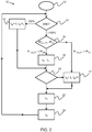
- Figure 1 shows a method 5 of the invention.
- step 6 the output power of the power source is determined.
- step 7 the output power of the power source is compared to the maximum input power of the battery.
- step 8 a ratio for distributing power to the battery or the power grid is determined based on the comparison made in step 7.
- step 9 the power is distributed from the power source to the battery or the power grid in divisions of time according to the ratio determined in step 8.
- P max_bat is the maximum input power of the battery, measured in kW
- V batt is the voltage at the battery terminal, measured in V
- I max_bat is the maximum battery charging current, measured in A.
- the power output of the power source will be greater than the maximum power input of the battery.
- the potential power that the power source is capable of generating above the maximum power input of the battery is unutilized when charging the battery.
- the power grid carries no such limitation and may utilize the full range of the power source. Further, it is important to ensure that the battery receives sufficient charge. Thus, a balance should be found for the benefit of the whole system including the battery and the power grid.
- the power output is less than or equal to the maximum power input of the battery, the power may be fully utilized by either the battery for energy storage. Further, if the power output is greater than the maximum input power of the battery, the power may be at least partly utilized by the power grid, meaning that an optimal system would shift the power distribution ratio in favor of feeding into the power grid to reduce power loss.
- t is the total time period, for example solar radiation period
- t k is a discrete time slot, for example ten minutes
- n is the total number of discrete time slots in the total time period, for example one hundred and forty four in this case.
- t gk is the time division of the discrete time slot, t k , for distributing power to the power grid and t bk is the time division of t k for distributing power to the battery for charging.
- the step of determining an output power of the power source, step 6, may comprise determining the maximum output power of the power source during the proceeding time slot.
- P k max_PV is the maximum power output of the power source during time slot k, measured in kW
- V k MPP is the voltage of the power source at its maximum power point in time slot k, measured in V
- I k MPP is the current of the power source at its maximum power point in time slot k, measured in A.
- the P is in the unit of kilo watts thus the product of V and I is divided by one thousand. It should be understood that there are various technologies for maximum power tracking commonly used in photovoltaic systems.
- the ratio for distributing power to the battery or the power grid may be more accurately calculated. For instance, in a time slot where the output power of the power source is below the maximum input power of the battery, the ratio may preferentially distribute power to the battery. In the case where the maximum output power for the time slot had been determined from the power source, for example by measuring light levels for a solar panel, the ratio may have taken into account the power output rising above the maximum input power of the battery and shown preferential distribution of power to the power grid in the later division of the time slot.
- P k loss is the power lost during time slot k
- P k max_PV is the maximum power produced by the power source during time slot k
- P k batt is the power supplied to the battery during time slot k, all of which are measured in kW.
- V k batt is the voltage at the terminal of the battery at the beginning of time slot k, measured in V
- I k batt is the charging current of the battery at the beginning of time slot k, measured in A.
- the method may also comprise a step for determining the state of charge of the battery. This step would further optimize the system for minimizing power loss. For example, if the battery is fully charged, any power distributed to the battery would be wasted. However, if it is known that the battery is full charged, the power distribution ratio may reflect this and preferentially distribute power to the power grid for that time slot.
- E bat_deficit is the energy required to charge a battery from its initial state of charge to full capacity, measured in kWh
- SOC ini is the initial state of charge of the battery
- V batt is the voltage at the battery terminal, measured in V
- B cap is the total capacity of the battery, measured in Ah.
- Figure 2 shows an exemplary method 10 for determining the ratio in step 8.
- step 12 the method begins.
- step 14 the state of charge of the battery is determined. If the battery is fully charged then the method proceeds to step 15, which skips battery charging and distributes all of the output power to grid feeding, otherwise the method proceeds to step 16.
- step 16 the insolation of the PV panel is determined and compared to the minimum insolation value. If the insolation of the PV panel is less than minimum insolation value, meaning the solar radiation is low, the method proceeds to step 17, which skips grid feeding and distributes all of the output power to battery charging, otherwise the method proceeds to step 18.
- step 18 the ratio for distributing power to the battery or the power grid is determined.
- the value of t gk may increase and the value of t bk may correspondingly decrease as the output power of the power source increases above the maximum input power of the battery.
- step 20 the grid is tested to determine whether the grid is available for power feed-in. If the grid is not available the method proceeds to step 17, however, if the grid is available then the method proceeds to step 22.
- the method then proceeds to step 20.
- step 17 either the output power of the power source has been determined to be less than or equal to the maximum input power of the battery or the power grid has been determined to be unavailable for power feed-in.
- step 22 the battery is charged for a division of the time slot.
- the length of this time division is determined by the ratio determined in step 18 or by the predetermined ratios in steps 15 or 17 if the required conditions are met.
- step 24 the power is fed into the power grid for a division of the time slot.
- the length of this time division is determined by subtracting the time spent charging the battery from the total time of that time slot.
- the method returns to the beginning step 12 and starts the process again, repeating the method for every time slot.
- the method may interchange steps 22 and 24, so that the power is fed into the grid first and then the power is used to charge the battery in the second time division.
- This may be an advantageous arrangement in situations where the power output is above the maximum input power of the battery at the beginning of a time slot, but is decreasing. In this case, power loss may be minimized by diverting power to the grid in the first time division as it may be fully utilized at a high power output. As the power output is decreasing over the time slot, when the power is diverted to the battery, less power will be wasted compared to charging the battery first and feeding into the grid afterwards. Whether the output power of the power source is decreasing or increasing may be determined by the output power data calculated in previous time slots.
- a certain time in a day can also be used as a sufficient condition for distributing all of the output power from the PV panel to charge the battery if it is not fully charged. For example, if the time comes to 15:00 and the battery is not fully charged, the controller may distribute all of the output power to charge the battery, regardless of the power loss, in order to avoid a low state of charge of the battery in the evening.
- the battery may be charged in constant current mode until the state of charge of the battery reaches 85%, at which point the battery is charged in constant voltage mode until the state of charge of the battery reaches 100%.
- the battery requires a decreasing amount of power in order to charge as it approaches a state of charge of 100%.
- This method becomes effective once the battery has attained a state of charge of 85%, under which it is more efficient to charge the battery in constant current mode.
- constant voltage mode required a lower power requirement to charge the battery, it may also be employed when the power output of the power source is below the maximum input power of the battery.
- B total is the battery capacity at the end of the day, measured in Ah
- SOC ini is the initial state of charge of the battery, measured as a percentage
- B cap is the total capacity of the battery, measured in Ah
- I bk is the charging current of the battery over time slot k, measured in A
- t bk is the time division of time slot k for charging the battery. The sum represents the total charge fed to the battery over the total time period, t.
- Figure 3 shows a graph 30 of output power 32 against time 34.
- the shape of the graph is based on the power output of a solar panel over a solar radiation period. At the beginning of the solar radiation period, the solar panel receives very little insolation and so the output power levels are low. As the sun rises, so do the output power levels, peaking at midday and then decreasing along with the setting of the sun.
- the time axis of the graph has been divided into regular time slots 36, during which the methods shown in Figures 1 and 2 may occur.
- the time slots may be further divided into time divisions for distributing power to the battery 37 or the power grid 38. The length of these time divisions is governed by the ratio determined in step 8 of Figure 1 and further detailed in Figure 2 .
- the output power shown along axis 32
- the power is distributed to the battery for charging.
- the energy supplied to the battery is shown by area 40 shaded by grids.
- the power source When the output power rises above the maximum input power level of the battery, the power source is limited to producing power at this level for as long as the power is being distributed to the battery for charging.
- the energy that is unutilized and lost through this limitation is shown by area 41 shaded by lines.
- the ratio for distributing power to the grid is increased for time slots where the output power level is above the maximum power input for the battery.
- the energy supplied to the grid is shown by area 42 shaded by dots. It can be seen that the higher the output power of the PV panel, the more a time slot is used for grid feeding and the less it is used for battery charging. In the middle time slot, the whole time slot is used for grid feeding.
- FIG 4 shows a control system 50 for implementing the methods shown in Figures 1 and 2 for a street lighting system comprising a battery 52 and a solar photovoltaic array 54 with grid 56 feed-in capabilities.
- the photovoltaic array produces DC power which must be fed through a grid feed-in inverter 57 in order to transform it into AC power, suitable for use by the power grid.
- the power produced by the photovoltaic array may not be exactly the same as the ideal power to charge the battery and so it is passed through a maximum power point tracking (MPPT) charge controller 58, which is a DC to DC converter that may optimize the match between the power output and the battery charging requirements.
- MPPT maximum power point tracking
- the system 50 is controlled by a controller 59 that operates a switch 60 which may distribute the power produced by the photovoltaic array 54 to the battery 52 or the grid 56.
- the controller uses information such as the current 62 and voltage 64 ratings of the battery, as well as the current insolation levels 66. From the battery ratings, the maximum input power of the battery may be determined and compared with the output power of the photovoltaic array, which may be predicted using the measured insolation levels.
- Ins k is the insolation level measured in time slot k, measured in W/m
- PV cap is the peak output power of the photovoltaic array under full insolation, measured in kWp.
- PV E is the total energy generated by the photovoltaic array over the total time period, t, measured in kWh
- Ins is the average daily insolation level, measured in W/m
- PV cap is as defined above.
- Ins hi_bat is the insolation level at which the power output of the photovoltaic array is equal to the maximum input power of the battery, measured in W/m and the other terms are as defined above.
- the controller 59 determines that the power output of the photovoltaic array 54 is greater than the maximum power input of the battery 52, or is likely to rise above this level based on the current insolation levels 66, the controller will determine a ratio for dividing the time of a time slot into a period for distributing the power to the battery for charging and a period for distributing the power to the power grid.
- the power from the battery 52 may then be passed through a DC bus regulator 68 and used to power the LEDs systems 70 that comprise the street light.
- This system is most efficient when the maximum output power of the power source is large in comparison to the maximum input power of the battery.
- Figure 5 shows a graph of insolation, measured in W/m 2 , against time, measured in hours, for three separate days.
- the line 80 shows the insolation levels for a day of full sunshine
- line 81 shows the insolation levels for a day of partial sunshine
- line 82 shows the insolation levels for a completely overcast day.
- Figures 6A to 6D show graphs of energy, measured in kWh, against time, measured in hours, comparing the energy distribution between a known control method and the proposed method described in Figures 1 and 2 .
- the control method is employed for the sample system described in Figure 4 based on the insolation levels 80 and 81 as shown in Figure 5 .
- the depth of discharge of the battery is maintained at 70%, meaning that the battery maintains a minimum charge of 30%, and battery charging current is set corresponding to a C-rate of 0.12C.
- constant current mode of battery charging is employed until the state of charge of the battery reaches 85%, followed by constant voltage mode until the SOC of the battery reaches 100%.
- Constant voltage mode is used only when the power output of the photovoltaic array is equal to or less than the maximum input power of the battery, or after 3:00PM, whichever is earlier. This is done so as to ensure that the battery is fully charged at the end of the day. It is assumed that all the various parts of the system such as the MPPT charge controller and grid feed-in inverter are operating at 100% efficiency.
- the battery is assumed to have an SOC of 30% at the start of the day and the duration of each time period, t k , is taken as 10 minutes or 1/6 hours.
- Figures 6A and 6B show a comparison between a known control method and the proposed control method on a day with high insolation levels, meaning a sunny day, as shown by line 80 in Figure 5 .
- the known control strategy shown in Figure 6A results in a high level of energy loss 41, of about 23.5%.
- the energy loss 41 may be reduced to about 8%, reducing the loss by nearly 66%.
- Figures 6C and 6D show the energy distribution on a partially sunny day, as shown by line 81 in Figure 5 , using the known and proposed control methods, respectively.
- the energy loss 41 is about 11.6% using known control method and 6.3% using the proposed method.
- Figures 6A to 6D show the proportions of the energy distributions at a given time, rather than the explicit time divisions for a given time slot, as shown in Figure 3 .
- the method may comprise dividing the solar radiation period into 10 - 200 time slots, t k .
- Successive time slots durations may not be the same and may depend on the time of day. For example, a time slot at midday may be shorter than a time slot at 8am as a change in weather conditions, such as an increase in cloud coverage, will have a larger effect on the insolation levels at midday, meaning that the system will have to respond rapidly in order to maintain efficiency.
- the peak power generation capability of the power source may be between 0.5 and 5kWp and the battery may be rated between 12 and 72V.
- the battery is for example a lead-acid battery.
- Table 1 Time (HH:MM) Global Horizontal Insolation (GHI) (W/m2) 22/08/2005 05/08/2005 16/08/2005 6:00 33 32 32 7:00 234 150 135 8:00 470 398 279 9:00 585 368 369 10:00 835 571 364 11:00 959 510 416 12:00 989 736 326 13:00 941 704 310 14:00 703 480 314
- the above table shows that the unutilized energy in the proposed solution is reduced by more than 10% compared to a known control method.
- the energy stored in the battery for the proposed solution is almost the same as the known method, while the energy for grid feeding is increased by more than 50% compared to the known control method.
Landscapes
- Engineering & Computer Science (AREA)
- Power Engineering (AREA)
- General Engineering & Computer Science (AREA)
- Supply And Distribution Of Alternating Current (AREA)
- Charge And Discharge Circuits For Batteries Or The Like (AREA)
Applications Claiming Priority (2)
| Application Number | Priority Date | Filing Date | Title |
|---|---|---|---|
| IN201641034680 | 2016-10-10 | ||
| EP17158648 | 2017-03-01 |
Publications (2)
| Publication Number | Publication Date |
|---|---|
| EP3306772A1 EP3306772A1 (en) | 2018-04-11 |
| EP3306772B1 true EP3306772B1 (en) | 2019-07-10 |
Family
ID=59997290
Family Applications (1)
| Application Number | Title | Priority Date | Filing Date |
|---|---|---|---|
| EP17195436.5A Active EP3306772B1 (en) | 2016-10-10 | 2017-10-09 | A method and system for optimally distributing power between a battery and a power grid |
Country Status (5)
| Country | Link |
|---|---|
| US (1) | US10411641B2 (zh) |
| EP (1) | EP3306772B1 (zh) |
| CN (1) | CN109792154B (zh) |
| ES (1) | ES2748298T3 (zh) |
| WO (1) | WO2018069221A1 (zh) |
Families Citing this family (9)
| Publication number | Priority date | Publication date | Assignee | Title |
|---|---|---|---|---|
| EP3108562A1 (en) * | 2014-02-21 | 2016-12-28 | Philips Lighting Holding B.V. | Power point tracking via solar-battery-converter |
| CN109353242B (zh) * | 2018-11-13 | 2021-11-09 | 国网电动汽车(山西)服务有限公司 | 一种智能充电桩系统实现双向有序充放电的充电算法 |
| US11205896B2 (en) * | 2018-11-21 | 2021-12-21 | Black & Decker Inc. | Solar power system |
| CN109473999B (zh) * | 2018-12-28 | 2022-07-15 | 阳光新能源开发股份有限公司 | 一种光储功率分配方法及装置 |
| EP3800759A1 (en) * | 2019-10-02 | 2021-04-07 | Fronius International GmbH | System and method for operating an inverter |
| CN112036735B (zh) * | 2020-08-28 | 2023-11-03 | 北方工业大学 | 一种用于光伏电站的储能系统的储能容量规划方法及系统 |
| CN112290597B (zh) * | 2020-11-23 | 2022-05-06 | 珠海格力电器股份有限公司 | 供电系统 |
| US20230178991A1 (en) * | 2021-12-07 | 2023-06-08 | Ohmium International, Inc. | Integrated solar to long term energy storage system with weather sensing |
| CN117639081B (zh) * | 2024-01-23 | 2024-04-30 | 深圳市德兰明海新能源股份有限公司 | 一种光伏储能逆变并机系统及其光伏能量调度方法 |
Family Cites Families (19)
| Publication number | Priority date | Publication date | Assignee | Title |
|---|---|---|---|---|
| US6933627B2 (en) * | 1991-01-08 | 2005-08-23 | Nextek Power Systems Inc. | High efficiency lighting system |
| WO2011016273A1 (ja) * | 2009-08-04 | 2011-02-10 | 日本電気株式会社 | エネルギーシステム |
| US20110084646A1 (en) * | 2009-10-14 | 2011-04-14 | National Semiconductor Corporation | Off-grid led street lighting system with multiple panel-storage matching |
| US8427118B2 (en) * | 2009-10-26 | 2013-04-23 | General Electric Company | Systems and methods for regulating power in renewable energy sources |
| JP2011125122A (ja) * | 2009-12-09 | 2011-06-23 | Sony Corp | バッテリ制御システム、バッテリ制御装置、バッテリ制御方法およびプログラム |
| WO2011093419A1 (ja) | 2010-01-28 | 2011-08-04 | 三洋電機株式会社 | 電力供給方法、コンピュータ読み取り可能な記録媒体および発電システム |
| US8914158B2 (en) * | 2010-03-11 | 2014-12-16 | Aes Corporation, The | Regulation of contribution of secondary energy sources to power grid |
| JP5617578B2 (ja) * | 2010-12-03 | 2014-11-05 | ソニー株式会社 | 配電システム及び配電方法 |
| US9819218B2 (en) * | 2011-09-28 | 2017-11-14 | Kyocera Corporation | Power conditioner system and power-storage power conditioner |
| JP5990897B2 (ja) * | 2011-11-25 | 2016-09-14 | ソニー株式会社 | 電力制御装置、送電装置、および電力制御システム |
| CA2779896A1 (en) * | 2012-06-13 | 2013-12-13 | Clear Blue Technologies Inc. | System for the monitoring and maintenance of remote autonomously powered lighting installations |
| JP2014039389A (ja) * | 2012-08-15 | 2014-02-27 | Honda Motor Co Ltd | 再生可能エネルギ貯電・充電管理システム |
| JP5900249B2 (ja) * | 2012-08-31 | 2016-04-06 | 株式会社デンソー | 電力供給システム |
| WO2014074703A1 (en) * | 2012-11-07 | 2014-05-15 | Zeroenergy Buildings, Inc. | Energy efficient cold storage units |
| US9774190B2 (en) * | 2013-09-09 | 2017-09-26 | Inertech Ip Llc | Multi-level medium voltage data center static synchronous compensator (DCSTATCOM) for active and reactive power control of data centers connected with grid energy storage and smart green distributed energy sources |
| CN103582100B (zh) * | 2013-10-15 | 2016-08-31 | 西安电子科技大学 | 一种在动态能量获取下的ofdma下行系统的动态资源分配方法 |
| KR101871020B1 (ko) * | 2014-03-20 | 2018-07-19 | 엘에스산전 주식회사 | 태양광 인버터를 이용한 에너지 저장 장치의 배터리 충전 시스템 |
| CN103944492A (zh) | 2014-05-08 | 2014-07-23 | 阳光电源股份有限公司 | 一种逆变器及光伏发电系统 |
| JP2017093223A (ja) * | 2015-11-13 | 2017-05-25 | 株式会社東芝 | 受電装置、送電装置、及び無線電力伝送システム |
-
2017
- 2017-10-09 EP EP17195436.5A patent/EP3306772B1/en active Active
- 2017-10-09 ES ES17195436T patent/ES2748298T3/es active Active
- 2017-10-09 CN CN201780062477.4A patent/CN109792154B/zh active Active
- 2017-10-09 WO PCT/EP2017/075626 patent/WO2018069221A1/en active Application Filing
- 2017-10-10 US US15/728,802 patent/US10411641B2/en active Active
Non-Patent Citations (1)
| Title |
|---|
| None * |
Also Published As
| Publication number | Publication date |
|---|---|
| ES2748298T3 (es) | 2020-03-16 |
| US20180102728A1 (en) | 2018-04-12 |
| WO2018069221A1 (en) | 2018-04-19 |
| CN109792154A (zh) | 2019-05-21 |
| US10411641B2 (en) | 2019-09-10 |
| CN109792154B (zh) | 2023-06-30 |
| EP3306772A1 (en) | 2018-04-11 |
Similar Documents
| Publication | Publication Date | Title |
|---|---|---|
| EP3306772B1 (en) | A method and system for optimally distributing power between a battery and a power grid | |
| Garcia et al. | Optimal energy management system for stand-alone wind turbine/photovoltaic/hydrogen/battery hybrid system with supervisory control based on fuzzy logic | |
| García-Triviño et al. | Control and operation of power sources in a medium-voltage direct-current microgrid for an electric vehicle fast charging station with a photovoltaic and a battery energy storage system | |
| US9825474B2 (en) | Secondary battery system with plural batteries and method of distributing charge/discharge power | |
| Glavin et al. | Optimisation of a photovoltaic battery ultracapacitor hybrid energy storage system | |
| Xu et al. | Optimal sizing of standalone hybrid wind/PV power systems using genetic algorithms | |
| JP7301997B2 (ja) | 最適化器、太陽光発電システム、及び太陽電池モジュールのためのiv曲線スキャニング方法 | |
| US9337682B2 (en) | Charging control device, solar power generation system and charging control method | |
| US9148020B2 (en) | Method of controlling a battery, computer readable recording medium, electric power generation system and device controlling a battery | |
| US20120228950A1 (en) | Stabilization system, power supply system, control method of the master management device and program for the master management device | |
| CN110289622B (zh) | 一种光储充能量路由器的日前经济优化调度方法 | |
| US9502903B2 (en) | Energy management systems and methods | |
| EP4246751A1 (en) | Method of controlling of battery energy storage system of power system with high dynamic loads | |
| EP3616289B1 (en) | Control system and method for an energy storage system | |
| CN104836247A (zh) | 实现储能容量动态优化的光储微网系统 | |
| JP5841279B2 (ja) | 電力充電供給装置 | |
| CN109120006B (zh) | 一种离网光伏系统负载管理方法及系统 | |
| Bampoulas et al. | Provision of frequency regulation by a residential microgrid integrating PVs, energy storage and electric vehicle | |
| CN115912417A (zh) | 基于模型预测的直流微电网分布式储能系统控制方法 | |
| CN110768274B (zh) | 一种孤立微电网的功率控制方法和装置 | |
| WO2013046509A1 (ja) | 給電システム及び給電方法 | |
| CN109599898B (zh) | 提高分布式电源消纳的控制方法及装置 | |
| CN107933356B (zh) | 一种电动车供电系统 | |
| JP7119118B2 (ja) | 電力変換装置の制御方法および電力変換装置 | |
| CN110417002A (zh) | 一种孤岛微电网能量模型的优化方法 |
Legal Events
| Date | Code | Title | Description |
|---|---|---|---|
| PUAI | Public reference made under article 153(3) epc to a published international application that has entered the european phase |
Free format text: ORIGINAL CODE: 0009012 |
|
| STAA | Information on the status of an ep patent application or granted ep patent |
Free format text: STATUS: THE APPLICATION HAS BEEN PUBLISHED |
|
| AK | Designated contracting states |
Kind code of ref document: A1 Designated state(s): AL AT BE BG CH CY CZ DE DK EE ES FI FR GB GR HR HU IE IS IT LI LT LU LV MC MK MT NL NO PL PT RO RS SE SI SK SM TR |
|
| AX | Request for extension of the european patent |
Extension state: BA ME |
|
| STAA | Information on the status of an ep patent application or granted ep patent |
Free format text: STATUS: REQUEST FOR EXAMINATION WAS MADE |
|
| 17P | Request for examination filed |
Effective date: 20181011 |
|
| RBV | Designated contracting states (corrected) |
Designated state(s): AL AT BE BG CH CY CZ DE DK EE ES FI FR GB GR HR HU IE IS IT LI LT LU LV MC MK MT NL NO PL PT RO RS SE SI SK SM TR |
|
| RAP1 | Party data changed (applicant data changed or rights of an application transferred) |
Owner name: PHILIPS LIGHTING HOLDING B.V. |
|
| GRAP | Despatch of communication of intention to grant a patent |
Free format text: ORIGINAL CODE: EPIDOSNIGR1 |
|
| STAA | Information on the status of an ep patent application or granted ep patent |
Free format text: STATUS: GRANT OF PATENT IS INTENDED |
|
| INTG | Intention to grant announced |
Effective date: 20190208 |
|
| RAP1 | Party data changed (applicant data changed or rights of an application transferred) |
Owner name: SIGNIFY HOLDING B.V. |
|
| GRAS | Grant fee paid |
Free format text: ORIGINAL CODE: EPIDOSNIGR3 |
|
| GRAA | (expected) grant |
Free format text: ORIGINAL CODE: 0009210 |
|
| STAA | Information on the status of an ep patent application or granted ep patent |
Free format text: STATUS: THE PATENT HAS BEEN GRANTED |
|
| AK | Designated contracting states |
Kind code of ref document: B1 Designated state(s): AL AT BE BG CH CY CZ DE DK EE ES FI FR GB GR HR HU IE IS IT LI LT LU LV MC MK MT NL NO PL PT RO RS SE SI SK SM TR |
|
| REG | Reference to a national code |
Ref country code: GB Ref legal event code: FG4D |
|
| REG | Reference to a national code |
Ref country code: CH Ref legal event code: EP Ref country code: AT Ref legal event code: REF Ref document number: 1154533 Country of ref document: AT Kind code of ref document: T Effective date: 20190715 |
|
| REG | Reference to a national code |
Ref country code: IE Ref legal event code: FG4D |
|
| REG | Reference to a national code |
Ref country code: DE Ref legal event code: R096 Ref document number: 602017005178 Country of ref document: DE |
|
| REG | Reference to a national code |
Ref country code: NL Ref legal event code: MP Effective date: 20190710 |
|
| REG | Reference to a national code |
Ref country code: LT Ref legal event code: MG4D |
|
| REG | Reference to a national code |
Ref country code: AT Ref legal event code: MK05 Ref document number: 1154533 Country of ref document: AT Kind code of ref document: T Effective date: 20190710 |
|
| PG25 | Lapsed in a contracting state [announced via postgrant information from national office to epo] |
Ref country code: AT Free format text: LAPSE BECAUSE OF FAILURE TO SUBMIT A TRANSLATION OF THE DESCRIPTION OR TO PAY THE FEE WITHIN THE PRESCRIBED TIME-LIMIT Effective date: 20190710 Ref country code: NL Free format text: LAPSE BECAUSE OF FAILURE TO SUBMIT A TRANSLATION OF THE DESCRIPTION OR TO PAY THE FEE WITHIN THE PRESCRIBED TIME-LIMIT Effective date: 20190710 Ref country code: BG Free format text: LAPSE BECAUSE OF FAILURE TO SUBMIT A TRANSLATION OF THE DESCRIPTION OR TO PAY THE FEE WITHIN THE PRESCRIBED TIME-LIMIT Effective date: 20191010 Ref country code: SE Free format text: LAPSE BECAUSE OF FAILURE TO SUBMIT A TRANSLATION OF THE DESCRIPTION OR TO PAY THE FEE WITHIN THE PRESCRIBED TIME-LIMIT Effective date: 20190710 Ref country code: NO Free format text: LAPSE BECAUSE OF FAILURE TO SUBMIT A TRANSLATION OF THE DESCRIPTION OR TO PAY THE FEE WITHIN THE PRESCRIBED TIME-LIMIT Effective date: 20191010 Ref country code: HR Free format text: LAPSE BECAUSE OF FAILURE TO SUBMIT A TRANSLATION OF THE DESCRIPTION OR TO PAY THE FEE WITHIN THE PRESCRIBED TIME-LIMIT Effective date: 20190710 Ref country code: LT Free format text: LAPSE BECAUSE OF FAILURE TO SUBMIT A TRANSLATION OF THE DESCRIPTION OR TO PAY THE FEE WITHIN THE PRESCRIBED TIME-LIMIT Effective date: 20190710 Ref country code: PT Free format text: LAPSE BECAUSE OF FAILURE TO SUBMIT A TRANSLATION OF THE DESCRIPTION OR TO PAY THE FEE WITHIN THE PRESCRIBED TIME-LIMIT Effective date: 20191111 Ref country code: FI Free format text: LAPSE BECAUSE OF FAILURE TO SUBMIT A TRANSLATION OF THE DESCRIPTION OR TO PAY THE FEE WITHIN THE PRESCRIBED TIME-LIMIT Effective date: 20190710 |
|
| PG25 | Lapsed in a contracting state [announced via postgrant information from national office to epo] |
Ref country code: LV Free format text: LAPSE BECAUSE OF FAILURE TO SUBMIT A TRANSLATION OF THE DESCRIPTION OR TO PAY THE FEE WITHIN THE PRESCRIBED TIME-LIMIT Effective date: 20190710 Ref country code: RS Free format text: LAPSE BECAUSE OF FAILURE TO SUBMIT A TRANSLATION OF THE DESCRIPTION OR TO PAY THE FEE WITHIN THE PRESCRIBED TIME-LIMIT Effective date: 20190710 Ref country code: GR Free format text: LAPSE BECAUSE OF FAILURE TO SUBMIT A TRANSLATION OF THE DESCRIPTION OR TO PAY THE FEE WITHIN THE PRESCRIBED TIME-LIMIT Effective date: 20191011 Ref country code: IS Free format text: LAPSE BECAUSE OF FAILURE TO SUBMIT A TRANSLATION OF THE DESCRIPTION OR TO PAY THE FEE WITHIN THE PRESCRIBED TIME-LIMIT Effective date: 20191110 Ref country code: AL Free format text: LAPSE BECAUSE OF FAILURE TO SUBMIT A TRANSLATION OF THE DESCRIPTION OR TO PAY THE FEE WITHIN THE PRESCRIBED TIME-LIMIT Effective date: 20190710 |
|
| REG | Reference to a national code |
Ref country code: ES Ref legal event code: FG2A Ref document number: 2748298 Country of ref document: ES Kind code of ref document: T3 Effective date: 20200316 |
|
| PG25 | Lapsed in a contracting state [announced via postgrant information from national office to epo] |
Ref country code: TR Free format text: LAPSE BECAUSE OF FAILURE TO SUBMIT A TRANSLATION OF THE DESCRIPTION OR TO PAY THE FEE WITHIN THE PRESCRIBED TIME-LIMIT Effective date: 20190710 |
|
| PG25 | Lapsed in a contracting state [announced via postgrant information from national office to epo] |
Ref country code: EE Free format text: LAPSE BECAUSE OF FAILURE TO SUBMIT A TRANSLATION OF THE DESCRIPTION OR TO PAY THE FEE WITHIN THE PRESCRIBED TIME-LIMIT Effective date: 20190710 Ref country code: DK Free format text: LAPSE BECAUSE OF FAILURE TO SUBMIT A TRANSLATION OF THE DESCRIPTION OR TO PAY THE FEE WITHIN THE PRESCRIBED TIME-LIMIT Effective date: 20190710 Ref country code: RO Free format text: LAPSE BECAUSE OF FAILURE TO SUBMIT A TRANSLATION OF THE DESCRIPTION OR TO PAY THE FEE WITHIN THE PRESCRIBED TIME-LIMIT Effective date: 20190710 Ref country code: PL Free format text: LAPSE BECAUSE OF FAILURE TO SUBMIT A TRANSLATION OF THE DESCRIPTION OR TO PAY THE FEE WITHIN THE PRESCRIBED TIME-LIMIT Effective date: 20190710 |
|
| PG25 | Lapsed in a contracting state [announced via postgrant information from national office to epo] |
Ref country code: IS Free format text: LAPSE BECAUSE OF FAILURE TO SUBMIT A TRANSLATION OF THE DESCRIPTION OR TO PAY THE FEE WITHIN THE PRESCRIBED TIME-LIMIT Effective date: 20200224 Ref country code: SK Free format text: LAPSE BECAUSE OF FAILURE TO SUBMIT A TRANSLATION OF THE DESCRIPTION OR TO PAY THE FEE WITHIN THE PRESCRIBED TIME-LIMIT Effective date: 20190710 Ref country code: MC Free format text: LAPSE BECAUSE OF FAILURE TO SUBMIT A TRANSLATION OF THE DESCRIPTION OR TO PAY THE FEE WITHIN THE PRESCRIBED TIME-LIMIT Effective date: 20190710 Ref country code: CZ Free format text: LAPSE BECAUSE OF FAILURE TO SUBMIT A TRANSLATION OF THE DESCRIPTION OR TO PAY THE FEE WITHIN THE PRESCRIBED TIME-LIMIT Effective date: 20190710 Ref country code: SM Free format text: LAPSE BECAUSE OF FAILURE TO SUBMIT A TRANSLATION OF THE DESCRIPTION OR TO PAY THE FEE WITHIN THE PRESCRIBED TIME-LIMIT Effective date: 20190710 |
|
| REG | Reference to a national code |
Ref country code: DE Ref legal event code: R097 Ref document number: 602017005178 Country of ref document: DE |
|
| PLBE | No opposition filed within time limit |
Free format text: ORIGINAL CODE: 0009261 |
|
| STAA | Information on the status of an ep patent application or granted ep patent |
Free format text: STATUS: NO OPPOSITION FILED WITHIN TIME LIMIT |
|
| PG2D | Information on lapse in contracting state deleted |
Ref country code: IS |
|
| PG25 | Lapsed in a contracting state [announced via postgrant information from national office to epo] |
Ref country code: LU Free format text: LAPSE BECAUSE OF NON-PAYMENT OF DUE FEES Effective date: 20191009 |
|
| 26N | No opposition filed |
Effective date: 20200603 |
|
| REG | Reference to a national code |
Ref country code: BE Ref legal event code: MM Effective date: 20191031 |
|
| PG25 | Lapsed in a contracting state [announced via postgrant information from national office to epo] |
Ref country code: BE Free format text: LAPSE BECAUSE OF NON-PAYMENT OF DUE FEES Effective date: 20191031 Ref country code: SI Free format text: LAPSE BECAUSE OF FAILURE TO SUBMIT A TRANSLATION OF THE DESCRIPTION OR TO PAY THE FEE WITHIN THE PRESCRIBED TIME-LIMIT Effective date: 20190710 |
|
| PG25 | Lapsed in a contracting state [announced via postgrant information from national office to epo] |
Ref country code: IE Free format text: LAPSE BECAUSE OF NON-PAYMENT OF DUE FEES Effective date: 20191009 |
|
| PG25 | Lapsed in a contracting state [announced via postgrant information from national office to epo] |
Ref country code: CY Free format text: LAPSE BECAUSE OF FAILURE TO SUBMIT A TRANSLATION OF THE DESCRIPTION OR TO PAY THE FEE WITHIN THE PRESCRIBED TIME-LIMIT Effective date: 20190710 |
|
| REG | Reference to a national code |
Ref country code: CH Ref legal event code: PL |
|
| PG25 | Lapsed in a contracting state [announced via postgrant information from national office to epo] |
Ref country code: LI Free format text: LAPSE BECAUSE OF FAILURE TO SUBMIT A TRANSLATION OF THE DESCRIPTION OR TO PAY THE FEE WITHIN THE PRESCRIBED TIME-LIMIT Effective date: 20201031 Ref country code: CH Free format text: LAPSE BECAUSE OF FAILURE TO SUBMIT A TRANSLATION OF THE DESCRIPTION OR TO PAY THE FEE WITHIN THE PRESCRIBED TIME-LIMIT Effective date: 20201031 |
|
| PG25 | Lapsed in a contracting state [announced via postgrant information from national office to epo] |
Ref country code: HU Free format text: LAPSE BECAUSE OF FAILURE TO SUBMIT A TRANSLATION OF THE DESCRIPTION OR TO PAY THE FEE WITHIN THE PRESCRIBED TIME-LIMIT; INVALID AB INITIO Effective date: 20171009 Ref country code: MT Free format text: LAPSE BECAUSE OF FAILURE TO SUBMIT A TRANSLATION OF THE DESCRIPTION OR TO PAY THE FEE WITHIN THE PRESCRIBED TIME-LIMIT Effective date: 20190710 |
|
| PG25 | Lapsed in a contracting state [announced via postgrant information from national office to epo] |
Ref country code: MK Free format text: LAPSE BECAUSE OF FAILURE TO SUBMIT A TRANSLATION OF THE DESCRIPTION OR TO PAY THE FEE WITHIN THE PRESCRIBED TIME-LIMIT Effective date: 20190710 |
|
| P01 | Opt-out of the competence of the unified patent court (upc) registered |
Effective date: 20230425 |
|
| PGFP | Annual fee paid to national office [announced via postgrant information from national office to epo] |
Ref country code: GB Payment date: 20231024 Year of fee payment: 7 |
|
| PGFP | Annual fee paid to national office [announced via postgrant information from national office to epo] |
Ref country code: ES Payment date: 20231110 Year of fee payment: 7 |
|
| PGFP | Annual fee paid to national office [announced via postgrant information from national office to epo] |
Ref country code: IT Payment date: 20231024 Year of fee payment: 7 Ref country code: FR Payment date: 20231026 Year of fee payment: 7 |
|
| PGFP | Annual fee paid to national office [announced via postgrant information from national office to epo] |
Ref country code: DE Payment date: 20231227 Year of fee payment: 7 |