EP3306717A1 - Verfahren zur vorbereitung eines katalysators mit einem träger aus polybenzimidazol-modifiziertem kohlenstoffmaterial - Google Patents
Verfahren zur vorbereitung eines katalysators mit einem träger aus polybenzimidazol-modifiziertem kohlenstoffmaterial Download PDFInfo
- Publication number
- EP3306717A1 EP3306717A1 EP17193718.8A EP17193718A EP3306717A1 EP 3306717 A1 EP3306717 A1 EP 3306717A1 EP 17193718 A EP17193718 A EP 17193718A EP 3306717 A1 EP3306717 A1 EP 3306717A1
- Authority
- EP
- European Patent Office
- Prior art keywords
- pbi
- supported catalyst
- carbonaceous material
- poly
- bibenzimidazole
- Prior art date
- Legal status (The legal status is an assumption and is not a legal conclusion. Google has not performed a legal analysis and makes no representation as to the accuracy of the status listed.)
- Withdrawn
Links
- 229920002480 polybenzimidazole Polymers 0.000 title claims abstract description 118
- 239000004693 Polybenzimidazole Substances 0.000 title claims abstract description 114
- 239000003054 catalyst Substances 0.000 title claims abstract description 75
- 239000003575 carbonaceous material Substances 0.000 title claims abstract description 56
- 238000000034 method Methods 0.000 title claims abstract description 14
- OKTJSMMVPCPJKN-UHFFFAOYSA-N Carbon Chemical compound [C] OKTJSMMVPCPJKN-UHFFFAOYSA-N 0.000 claims abstract description 25
- 239000002923 metal particle Substances 0.000 claims abstract description 21
- 238000010438 heat treatment Methods 0.000 claims abstract description 14
- 239000002041 carbon nanotube Substances 0.000 claims abstract description 11
- 229910021393 carbon nanotube Inorganic materials 0.000 claims abstract description 10
- 230000004048 modification Effects 0.000 claims abstract description 10
- 238000012986 modification Methods 0.000 claims abstract description 10
- 239000006229 carbon black Substances 0.000 claims abstract description 6
- 235000019241 carbon black Nutrition 0.000 claims abstract description 6
- 230000008021 deposition Effects 0.000 claims abstract description 5
- 229910021389 graphene Inorganic materials 0.000 claims abstract description 5
- BASFCYQUMIYNBI-UHFFFAOYSA-N platinum Chemical compound [Pt] BASFCYQUMIYNBI-UHFFFAOYSA-N 0.000 claims description 32
- 239000012528 membrane Substances 0.000 claims description 16
- 229910052697 platinum Inorganic materials 0.000 claims description 16
- 239000002243 precursor Substances 0.000 claims description 14
- 239000000446 fuel Substances 0.000 claims description 12
- 239000002245 particle Substances 0.000 claims description 12
- KDLHZDBZIXYQEI-UHFFFAOYSA-N Palladium Chemical compound [Pd] KDLHZDBZIXYQEI-UHFFFAOYSA-N 0.000 claims description 10
- 239000000203 mixture Substances 0.000 claims description 10
- 229910052751 metal Inorganic materials 0.000 claims description 7
- 239000002184 metal Substances 0.000 claims description 7
- 230000008569 process Effects 0.000 claims description 7
- 238000000151 deposition Methods 0.000 claims description 5
- 238000007254 oxidation reaction Methods 0.000 claims description 5
- 229910052763 palladium Inorganic materials 0.000 claims description 5
- 238000004519 manufacturing process Methods 0.000 claims description 4
- 230000003647 oxidation Effects 0.000 claims description 4
- 125000001989 1,3-phenylene group Chemical group [H]C1=C([H])C([*:1])=C([H])C([*:2])=C1[H] 0.000 claims description 2
- DPZVOQSREQBFML-UHFFFAOYSA-N 3h-pyrrolo[3,4-c]pyridine Chemical compound C1=NC=C2CN=CC2=C1 DPZVOQSREQBFML-UHFFFAOYSA-N 0.000 claims description 2
- 229910000990 Ni alloy Inorganic materials 0.000 claims description 2
- 229910001260 Pt alloy Inorganic materials 0.000 claims description 2
- 229910052741 iridium Inorganic materials 0.000 claims description 2
- GKOZUEZYRPOHIO-UHFFFAOYSA-N iridium atom Chemical compound [Ir] GKOZUEZYRPOHIO-UHFFFAOYSA-N 0.000 claims description 2
- -1 p -phenylene Chemical group 0.000 claims description 2
- 238000001179 sorption measurement Methods 0.000 claims description 2
- 238000002360 preparation method Methods 0.000 claims 5
- ZMXDDKWLCZADIW-UHFFFAOYSA-N N,N-Dimethylformamide Chemical compound CN(C)C=O ZMXDDKWLCZADIW-UHFFFAOYSA-N 0.000 description 18
- 239000000463 material Substances 0.000 description 17
- XLYOFNOQVPJJNP-UHFFFAOYSA-N water Substances O XLYOFNOQVPJJNP-UHFFFAOYSA-N 0.000 description 13
- LYCAIKOWRPUZTN-UHFFFAOYSA-N Ethylene glycol Chemical compound OCCO LYCAIKOWRPUZTN-UHFFFAOYSA-N 0.000 description 12
- AFVFQIVMOAPDHO-UHFFFAOYSA-N Methanesulfonic acid Chemical compound CS(O)(=O)=O AFVFQIVMOAPDHO-UHFFFAOYSA-N 0.000 description 12
- FXHOOIRPVKKKFG-UHFFFAOYSA-N N,N-Dimethylacetamide Chemical compound CN(C)C(C)=O FXHOOIRPVKKKFG-UHFFFAOYSA-N 0.000 description 12
- SECXISVLQFMRJM-UHFFFAOYSA-N N-Methylpyrrolidone Chemical compound CN1CCCC1=O SECXISVLQFMRJM-UHFFFAOYSA-N 0.000 description 12
- HHVIBTZHLRERCL-UHFFFAOYSA-N sulfonyldimethane Chemical compound CS(C)(=O)=O HHVIBTZHLRERCL-UHFFFAOYSA-N 0.000 description 12
- 229910052799 carbon Inorganic materials 0.000 description 11
- 239000006185 dispersion Substances 0.000 description 10
- 239000000523 sample Substances 0.000 description 9
- 238000000429 assembly Methods 0.000 description 8
- 230000000712 assembly Effects 0.000 description 8
- BDAGIHXWWSANSR-UHFFFAOYSA-N methanoic acid Natural products OC=O BDAGIHXWWSANSR-UHFFFAOYSA-N 0.000 description 8
- 239000002904 solvent Substances 0.000 description 7
- 238000002604 ultrasonography Methods 0.000 description 7
- 230000032683 aging Effects 0.000 description 6
- 230000015556 catabolic process Effects 0.000 description 6
- 238000006731 degradation reaction Methods 0.000 description 6
- 229940098779 methanesulfonic acid Drugs 0.000 description 6
- 238000006722 reduction reaction Methods 0.000 description 6
- 238000004626 scanning electron microscopy Methods 0.000 description 6
- 239000000725 suspension Substances 0.000 description 6
- 230000005540 biological transmission Effects 0.000 description 5
- 238000001035 drying Methods 0.000 description 5
- 230000009467 reduction Effects 0.000 description 5
- OSWFIVFLDKOXQC-UHFFFAOYSA-N 4-(3-methoxyphenyl)aniline Chemical compound COC1=CC=CC(C=2C=CC(N)=CC=2)=C1 OSWFIVFLDKOXQC-UHFFFAOYSA-N 0.000 description 4
- CSCPPACGZOOCGX-UHFFFAOYSA-N Acetone Chemical compound CC(C)=O CSCPPACGZOOCGX-UHFFFAOYSA-N 0.000 description 4
- 239000003638 chemical reducing agent Substances 0.000 description 4
- 235000019253 formic acid Nutrition 0.000 description 4
- 230000010287 polarization Effects 0.000 description 4
- 239000007787 solid Substances 0.000 description 4
- 238000003756 stirring Methods 0.000 description 4
- LFQSCWFLJHTTHZ-UHFFFAOYSA-N Ethanol Chemical compound CCO LFQSCWFLJHTTHZ-UHFFFAOYSA-N 0.000 description 3
- OKKJLVBELUTLKV-UHFFFAOYSA-N Methanol Chemical compound OC OKKJLVBELUTLKV-UHFFFAOYSA-N 0.000 description 3
- 238000004873 anchoring Methods 0.000 description 3
- 230000007547 defect Effects 0.000 description 3
- 229910052739 hydrogen Inorganic materials 0.000 description 3
- 125000004435 hydrogen atom Chemical class [H]* 0.000 description 3
- 239000012535 impurity Substances 0.000 description 3
- 239000007788 liquid Substances 0.000 description 3
- 230000001590 oxidative effect Effects 0.000 description 3
- 238000000926 separation method Methods 0.000 description 3
- 238000002411 thermogravimetry Methods 0.000 description 3
- KFZMGEQAYNKOFK-UHFFFAOYSA-N Isopropanol Chemical compound CC(C)O KFZMGEQAYNKOFK-UHFFFAOYSA-N 0.000 description 2
- PXHVJJICTQNCMI-UHFFFAOYSA-N Nickel Chemical compound [Ni] PXHVJJICTQNCMI-UHFFFAOYSA-N 0.000 description 2
- 238000013019 agitation Methods 0.000 description 2
- 150000001721 carbon Chemical class 0.000 description 2
- 239000008367 deionised water Substances 0.000 description 2
- 229910021641 deionized water Inorganic materials 0.000 description 2
- 239000012153 distilled water Substances 0.000 description 2
- 238000009826 distribution Methods 0.000 description 2
- 239000003792 electrolyte Substances 0.000 description 2
- 238000001914 filtration Methods 0.000 description 2
- 239000001257 hydrogen Substances 0.000 description 2
- 238000010348 incorporation Methods 0.000 description 2
- 238000011068 loading method Methods 0.000 description 2
- 238000010907 mechanical stirring Methods 0.000 description 2
- 239000002105 nanoparticle Substances 0.000 description 2
- 239000003960 organic solvent Substances 0.000 description 2
- 239000007800 oxidant agent Substances 0.000 description 2
- 230000000284 resting effect Effects 0.000 description 2
- RYGMFSIKBFXOCR-UHFFFAOYSA-N Copper Chemical compound [Cu] RYGMFSIKBFXOCR-UHFFFAOYSA-N 0.000 description 1
- 229920000557 Nafion® Polymers 0.000 description 1
- ATJFFYVFTNAWJD-UHFFFAOYSA-N Tin Chemical compound [Sn] ATJFFYVFTNAWJD-UHFFFAOYSA-N 0.000 description 1
- QVGXLLKOCUKJST-UHFFFAOYSA-N atomic oxygen Chemical compound [O] QVGXLLKOCUKJST-UHFFFAOYSA-N 0.000 description 1
- 230000015572 biosynthetic process Effects 0.000 description 1
- 238000006243 chemical reaction Methods 0.000 description 1
- 239000003795 chemical substances by application Substances 0.000 description 1
- 229910017052 cobalt Inorganic materials 0.000 description 1
- 239000010941 cobalt Substances 0.000 description 1
- GUTLYIVDDKVIGB-UHFFFAOYSA-N cobalt atom Chemical compound [Co] GUTLYIVDDKVIGB-UHFFFAOYSA-N 0.000 description 1
- 229910052802 copper Inorganic materials 0.000 description 1
- 239000010949 copper Substances 0.000 description 1
- 230000007797 corrosion Effects 0.000 description 1
- 238000005260 corrosion Methods 0.000 description 1
- 230000007423 decrease Effects 0.000 description 1
- 238000009792 diffusion process Methods 0.000 description 1
- 238000004090 dissolution Methods 0.000 description 1
- 230000000694 effects Effects 0.000 description 1
- 238000003487 electrochemical reaction Methods 0.000 description 1
- 125000001153 fluoro group Chemical group F* 0.000 description 1
- PCHJSUWPFVWCPO-UHFFFAOYSA-N gold Chemical compound [Au] PCHJSUWPFVWCPO-UHFFFAOYSA-N 0.000 description 1
- 229910052737 gold Inorganic materials 0.000 description 1
- 239000010931 gold Substances 0.000 description 1
- 238000007731 hot pressing Methods 0.000 description 1
- 230000006872 improvement Effects 0.000 description 1
- 238000011065 in-situ storage Methods 0.000 description 1
- 229910021645 metal ion Inorganic materials 0.000 description 1
- 239000002071 nanotube Substances 0.000 description 1
- 229910052759 nickel Inorganic materials 0.000 description 1
- 230000006911 nucleation Effects 0.000 description 1
- 238000010899 nucleation Methods 0.000 description 1
- 229910052760 oxygen Inorganic materials 0.000 description 1
- 239000001301 oxygen Substances 0.000 description 1
- 229920000642 polymer Polymers 0.000 description 1
- 238000010992 reflux Methods 0.000 description 1
- 238000000851 scanning transmission electron micrograph Methods 0.000 description 1
- 238000004544 sputter deposition Methods 0.000 description 1
- 239000000126 substance Substances 0.000 description 1
- 238000006467 substitution reaction Methods 0.000 description 1
- 239000000758 substrate Substances 0.000 description 1
- 238000003786 synthesis reaction Methods 0.000 description 1
- 238000007669 thermal treatment Methods 0.000 description 1
- 229910052718 tin Inorganic materials 0.000 description 1
- 239000011135 tin Substances 0.000 description 1
- 238000003828 vacuum filtration Methods 0.000 description 1
Images


Classifications
-
- H—ELECTRICITY
- H01—ELECTRIC ELEMENTS
- H01M—PROCESSES OR MEANS, e.g. BATTERIES, FOR THE DIRECT CONVERSION OF CHEMICAL ENERGY INTO ELECTRICAL ENERGY
- H01M4/00—Electrodes
- H01M4/86—Inert electrodes with catalytic activity, e.g. for fuel cells
- H01M4/90—Selection of catalytic material
- H01M4/92—Metals of platinum group
-
- C—CHEMISTRY; METALLURGY
- C25—ELECTROLYTIC OR ELECTROPHORETIC PROCESSES; APPARATUS THEREFOR
- C25B—ELECTROLYTIC OR ELECTROPHORETIC PROCESSES FOR THE PRODUCTION OF COMPOUNDS OR NON-METALS; APPARATUS THEREFOR
- C25B1/00—Electrolytic production of inorganic compounds or non-metals
- C25B1/01—Products
- C25B1/02—Hydrogen or oxygen
- C25B1/04—Hydrogen or oxygen by electrolysis of water
-
- C—CHEMISTRY; METALLURGY
- C25—ELECTROLYTIC OR ELECTROPHORETIC PROCESSES; APPARATUS THEREFOR
- C25B—ELECTROLYTIC OR ELECTROPHORETIC PROCESSES FOR THE PRODUCTION OF COMPOUNDS OR NON-METALS; APPARATUS THEREFOR
- C25B11/00—Electrodes; Manufacture thereof not otherwise provided for
- C25B11/04—Electrodes; Manufacture thereof not otherwise provided for characterised by the material
-
- H—ELECTRICITY
- H01—ELECTRIC ELEMENTS
- H01M—PROCESSES OR MEANS, e.g. BATTERIES, FOR THE DIRECT CONVERSION OF CHEMICAL ENERGY INTO ELECTRICAL ENERGY
- H01M4/00—Electrodes
- H01M4/86—Inert electrodes with catalytic activity, e.g. for fuel cells
- H01M4/90—Selection of catalytic material
- H01M4/92—Metals of platinum group
- H01M4/921—Alloys or mixtures with metallic elements
-
- H—ELECTRICITY
- H01—ELECTRIC ELEMENTS
- H01M—PROCESSES OR MEANS, e.g. BATTERIES, FOR THE DIRECT CONVERSION OF CHEMICAL ENERGY INTO ELECTRICAL ENERGY
- H01M4/00—Electrodes
- H01M4/86—Inert electrodes with catalytic activity, e.g. for fuel cells
- H01M4/90—Selection of catalytic material
- H01M4/92—Metals of platinum group
- H01M4/925—Metals of platinum group supported on carriers, e.g. powder carriers
- H01M4/926—Metals of platinum group supported on carriers, e.g. powder carriers on carbon or graphite
-
- Y—GENERAL TAGGING OF NEW TECHNOLOGICAL DEVELOPMENTS; GENERAL TAGGING OF CROSS-SECTIONAL TECHNOLOGIES SPANNING OVER SEVERAL SECTIONS OF THE IPC; TECHNICAL SUBJECTS COVERED BY FORMER USPC CROSS-REFERENCE ART COLLECTIONS [XRACs] AND DIGESTS
- Y02—TECHNOLOGIES OR APPLICATIONS FOR MITIGATION OR ADAPTATION AGAINST CLIMATE CHANGE
- Y02E—REDUCTION OF GREENHOUSE GAS [GHG] EMISSIONS, RELATED TO ENERGY GENERATION, TRANSMISSION OR DISTRIBUTION
- Y02E60/00—Enabling technologies; Technologies with a potential or indirect contribution to GHG emissions mitigation
- Y02E60/30—Hydrogen technology
- Y02E60/36—Hydrogen production from non-carbon containing sources, e.g. by water electrolysis
-
- Y—GENERAL TAGGING OF NEW TECHNOLOGICAL DEVELOPMENTS; GENERAL TAGGING OF CROSS-SECTIONAL TECHNOLOGIES SPANNING OVER SEVERAL SECTIONS OF THE IPC; TECHNICAL SUBJECTS COVERED BY FORMER USPC CROSS-REFERENCE ART COLLECTIONS [XRACs] AND DIGESTS
- Y02—TECHNOLOGIES OR APPLICATIONS FOR MITIGATION OR ADAPTATION AGAINST CLIMATE CHANGE
- Y02E—REDUCTION OF GREENHOUSE GAS [GHG] EMISSIONS, RELATED TO ENERGY GENERATION, TRANSMISSION OR DISTRIBUTION
- Y02E60/00—Enabling technologies; Technologies with a potential or indirect contribution to GHG emissions mitigation
- Y02E60/30—Hydrogen technology
- Y02E60/50—Fuel cells
Definitions
- the present invention relates to a process for preparing a metal catalyst supported by a carbonaceous material.
- This carbonaceous material also contains polybenzimidazole.
- the fields of use of the present invention relates in particular to fuel cells and electrolysers.
- a fuel cell makes it possible to transform chemical energy into electrical energy from a fuel, such as hydrogen, methanol, ethanol or formic acid. This energy conversion is performed at the core of the cell which generally comprises an anode, an electrolyte and a cathode.
- the proton exchange membrane fuel cell (PEMFC) electrolyte consists of a proton exchange membrane .
- PEMFCs comprise an electrode membrane assembly (AME) consisting of an anode, a proton exchange membrane and a cathode.
- the operation of the PEMFCs involves a fuel oxidation reaction at the anode, and an oxidant reduction reaction at the cathode.
- oxidation at the anode When the fuel is hydrogen, oxidation at the anode generates H + protons and electrons.
- the electrons are directed to the cathode via a circuit external to the fuel cell, while the protons pass through the membrane.
- the reduction of the oxidant (oxygen) makes it possible to form water in the presence of these protons and electrons.
- the electrodes of a battery comprise an active layer to ensure the electrochemical reactions.
- This active layer is therefore exposed to stringent conditions, particularly related to the oxidizing or reducing environment, to the possible strong local acidity, the appearance of hot spots, or the phenomena of dewatering and flooding.
- An active layer generally comprises a catalyst, for example nanoparticles supported by a carbonaceous material.
- a catalyst for example nanoparticles supported by a carbonaceous material.
- Commonly used carbon supports include spherical carbon black, planar graphene, and cylindrical carbon nanotubes (CNTs).
- the document EP 2 811 563 discloses a method of modifying the surface of carbon nanotubes with polybenzimidazole. This modification improves the resistance to degradation of the carbonaceous material.
- the surface condition of the highly graphitized supports has a disadvantage.
- the absence or near absence of defects decreases the number of anchor points where the catalyst can be deposited.
- the catalyst is deposited by reducing a precursor in the presence of the carbon support.
- metal ions are fixed on the anchoring points of the carbon support before being reduced to metal. Therefore, the ability of a carbon support to support a catalyst also depends on its surface condition. In other words, the potential number of nucleation points of the catalyst is generally proportional to the number of anchor points.
- the present invention provides a solution to this problem through a catalyst supported by a modified carbon material.
- the Applicant has developed a process involving the treatment of a carbonaceous material with a polybenzimidazole for use as a catalyst support.
- the catalyst obtained by this process has improved durability over conventional carbon-based catalysts. In addition, it has metal particles (catalyst) of smaller size, the dispersion is improved.
- the carbonaceous material C is heat-treated (step a)) prior to its modification with the PBI.
- This heat treatment is carried out at a temperature of between 1400 ° C. and 2300 ° C., advantageously between 1500 ° C. and 2000 ° C.
- the carbonaceous material C may especially consist of single-sheet carbon nanotubes or multi-layer carbon nanotubes.
- Carbon blacks are spherical while graphene is flat, and carbon nanotubes cylindrical.
- the material C t has a smaller amount of impurities than the material C, advantageously no impurity.
- impurity is meant any organic or inorganic trace (other than the carbonaceous material) from the precursors used in the synthesis of the carbonaceous material.
- the heat treatment is carried out for a period of between one hour and 24 hours, advantageously between two hours and twelve hours.
- the material C t is then modified with a polymer during step c).
- the heat-treated carbonaceous material C t from step a) is brought into contact with at least one polybenzimidazole (PBI).
- PBI polybenzimidazole
- This contact makes it possible to modify the carbonaceous material C t so as to form the C t -PBI material.
- the contacting makes it possible to modify the surface of the material C t with PBI. It is advantageously carried out by adsorption of at least one polybenzimidazole, especially in solution.
- PBI is advantageously chosen from the group comprising poly [2,2 '- (m-phenylene) -5,5'-bibenzimidazole]; poly [2,2 '- ( p -phenylene) -5,5'-bibenzimidazole]; poly (2,5-benzimidazole); poly [2,2 '- ( p -oxydiphenylene) -5,5'-bibenzimidazole]; poly (2,2 '- (m-phenylene) -5,5'-bibenzimidazole); poly (2,6- (2,6-naphthyliden) -1,7-dihydrobenzo [1,2-d; 4,5-d] diimidazole); poly (2,2 '- (2,6-naphthyliden) -5,5'-bibenzimidazole); poly (2,2 '- (2,6-pyridin) -5,5'-bibenzimidazole); partially or totally fluorinated polybenz
- the material C t is, prior to its contact with the PBI, dispersed in an organic solvent, for example using an ultrasound probe.
- This dispersion solvent may be selected from the group comprising dimethylacetamide (DMAc), N-methyl-2-pyrrolidone (NMP), dimethylsulfone (DMSO), dimethylformamide (DMF), and methanesulfonic acid (MSA).
- DMAc dimethylacetamide
- NMP N-methyl-2-pyrrolidone
- DMSO dimethylsulfone
- DMF dimethylformamide
- MSA methanesulfonic acid
- the PBI Prior to the contacting of step c), the PBI is also advantageously dissolved in an organic solvent.
- IBP can be solubilized in a solvent selected from the group consisting of dimethylacetamide (DMAc), N-methyl-2-pyrrolidone (NMP), dimethylsulfone (DMSO), dimethylformamide (DMF), and methanesulfonic acid (MSA). ).
- DMAc dimethylacetamide
- NMP N-methyl-2-pyrrolidone
- DMSO dimethylsulfone
- DMF dimethylformamide
- MSA methanesulfonic acid
- the bringing into contact between the material C t and the PBI can in particular be carried out by adding a suspension of C t in DMAc to a solution of PBI in DMAc.
- the material C t can be suspended in a solvent selected from the group comprising dimethylacetamide (DMAc), N-methyl-2-pyrrolidone (NMP), dimethylsulfone (DMSO), dimethylformamide (DMF), and methanesulfonic acid (MSA).
- DMAc dimethylacetamide
- NMP N-methyl-2-pyrrolidone
- DMSO dimethylsulfone
- DMF dimethylformamide
- MSA methanesulfonic acid
- the contacting time advantageously lasts between 10 minutes and 24 hours, more advantageously between one hour and twelve hours.
- step c) When step c) is carried out in solution, the bringing into contact is advantageously followed by a solid / liquid separation step making it possible to isolate the modified carbon material C t -PBI.
- the solid / liquid separation is advantageously carried out by filtration.
- the modified carbonaceous material C t -PBI is advantageously dried at a temperature between 60 ° C and 100 ° C, more preferably between 75 ° C and 85 ° C.
- the drying may especially be carried out in an oven or under vacuum.
- the duration of the drying is advantageously between one hour and 48 hours, more advantageously between twelve hours and 24 hours.
- the C t -PBI material resulting from the modification of C t with the PBI has a mass ratio between the carbonaceous material C t and the PBI advantageously between 50 and 95, more advantageously between 60 and 90.
- the C t -PBI obtained has a weight percentage of PBI advantageously between 5% and 50%, relative to the weight of C t -PBI, more preferably between 10% and 40%.
- step d metal particles M are deposited on the modified carbonaceous material C t -PBI (step e)).
- the metal particles M are particles of a metal having a degree of oxidation equal to 0, said metal being advantageously chosen from the group comprising platinum, platinum alloys (nickel, cobalt, gold, palladium, copper, tin and all other ternary or quaternary combinations), iridium, palladium (palladium nickel alloys).
- the deposition of the particles may be carried out in solution, in particular in the presence of a precursor of metal particles.
- the C t -PBI material is dispersed in a solvent advantageously chosen from the group comprising water, ethylene glycol, and formic acid.
- the dispersion of the material C t -PBI can be carried out using an ultrasound probe.
- the mixture containing the C t -PBI and the precursor is preferably mixed for a period between one hour and 24 hours prior to addition of the reducing agent. This stirring is carried out at a temperature between 25 ° C and 200 ° C, preferably between 35 ° C and 120 ° C.
- the metal particle precursor is chosen from the group comprising H 2 PtCl 6 ; K 2 PtCl 6 ⁇ in hydrated form (6H 2 O) or not; Na 2 PtCl 6 ⁇ in hydrated form (6H 2 O) or not; (NH 4 ) 2 PtCl 6 H 2 PtBr 6 ⁇ in hydrated form (xH 2 O) or not; H 2 Pt (OH) 6 ; and Pt (C 5 H 7 O 2 ) 2 .
- the dissolution of the metal particle precursor is advantageously carried out in a solvent chosen from the group comprising water, ethylene glycol, and formic acid.
- the precursor is reduced in the presence of a reducing agent so as to form in situ particles of a metal whose degree of oxidation is equal to 0.
- This reducing agent is advantageously chosen from the group comprising ethylene glycol, formic acid, and borohydrides, especially NaBH 4 . It may especially be the solvent of the suspension of C t -PBI and / or the solvent of the precursor solution.
- the reduction of the metal particle precursor is advantageously carried out at a temperature between 25 ° C and 200 ° C, more preferably between 50 ° C and 170 ° C.
- the duration of the reduction is advantageously between one hour and 24 hours, more advantageously between two hours and eighteen hours.
- the mixture may be subjected to solid / liquid separation to isolate the supported M / C t -PBI catalyst. This step is advantageously carried out by filtration.
- the supported M / C t -PBI catalyst can then be washed, for example with water and / or acetone.
- the supported catalyst M / C t -PBI thus obtained is advantageously dried, for example in an oven. Drying can be carried out at a temperature of between 60 ° C and 120 ° C, more preferably between 80 ° C and 100 ° C. The duration of the drying is advantageously between six hours and forty-eight hours, more advantageously between twelve hours and twenty-four hours.
- the M / C t -PBI thus obtained has a mass percentage of metal particles M advantageously between 5% and 60%, relative to the mass of M / C t -PBI, more advantageously between 10% and 50%.
- the present invention also relates to the supported catalyst obtained by the method detailed above and the electrode comprising this supported catalyst.
- this supported catalyst has particles of smaller size and better dispersed than in the supported catalysts obtained according to the methods of the prior art.
- the size of the metal particles (M) in the supported catalyst M / C t -PBI is advantageously between 1 nanometer and 5 nanometers, more advantageously between 2 nanometers and 5 nanometers. On the other hand, it is generally of the order of 5 nanometers to 6 nanometers when the carbonaceous material has not been modified with PBI.
- This catalyst is advantageously integrated in an electrode.
- An electrode comprising a supported catalyst according to the invention has a better performance and a better durability compared to the electrodes of the prior art.
- the electrode preferably a cathode, may be used in a proton exchange membrane fuel cell, in a battery or in a proton exchange membrane electrolyser.
- the present invention also relates to a proton exchange membrane fuel cell, a battery or a proton exchange membrane electrolyser comprising this electrode.
- platinum particles (M) are incorporated in a carbonaceous material (C), which has optionally been previously heat-treated and modified in the presence of PBI.
- an ultrasonic probe having a diameter of 13 mm was used with a Bioblock Scientific type device, model: Vibra-Cell TM 75041.
- the power of the device is 750 W (it operates at 20 kHz) .
- the operating power is related to the power of this unit.
- the operating mode called "pulsed" corresponds to one second running, one second off, all for the desired duration, for example 15 minutes.
- This treatment makes it possible to obtain thermally treated carbon nanotubes: C t .
- a carbon material (1 g C T or C) is dispersed in 100 mL of dimethylacetamide (DMAc) by using an ultrasonic probe. This carbonaceous material is then added to a solution of 1 g of PBI in 400 ml of DMAc. The mixture thus obtained is then stirred for 12 hours at room temperature.
- DMAc dimethylacetamide
- This mixture is then filtered and the solid obtained is rinsed three times with DMAc and then three times with distilled water.
- the carbonaceous material thus modified (C t -PBI or C-PBI) is dried for 48 hours in an oven at 95 ° C.
- the modified carbonaceous material 500 mg of C t -PBI or C-PBI is suspended in 50 ml of distilled water using an ultrasound probe (power: 70% operating by pulse; agitation: 1 second, rest time: 1 second) for 15 minutes.
- the suspension is then treated with the aid of an ultrasound probe (power: 70% operating by pulse, stirring time: 1 second, resting time: 1 second) for 15 minutes.
- an ultrasound probe power: 70% operating by pulse, stirring time: 1 second, resting time: 1 second
- This suspension is then added to 500 ml of ethylene glycol and then treated again with the aid of an ultrasound probe (power: 70% operating by pulse, stirring time: 1 second, resting time: 1 second ) for 15 minutes.
- the suspension is then heated to 110 ° C and kept under reflux for 12 hours.
- the supported catalyst (M / C-PBI or M / C -PBI t) is then recovered by vacuum filtration and rinsed several times with deionized water and acetone and then placed in an oven at 95 ° C for 24 hours for complete drying.
- Table 1 summarizes the catalysts that have been prepared and the amount of platinum incorporated.
- Table 1 Composition of Prepared Catalysts Catalyst supported Carbon material Amount of platinum (% by mass) INV-1 M / C t -PBI ( figure 1 ) C t -PBI 37 (% Pt / C t -PBI) CE-1 M / C t ( figure 2 ) C t 7 (% Pt / Ct ) CE-2 M / C-PBI ( figure 3 ) C-PBI 46 (% Pt / C-PBI) CE-3 M / C ( figure 4 ) VS 37 (% Pt / C)
- the percentage of PBI grafted onto the surface of the carbonaceous material was determined by thermogravimetric analysis (ATG) carried out under air ( figure 5 : loss of mass as a function of temperature). The first loss of mass observed around 450-500 ° C corresponds to the PBI.
- the second loss of mass above 550 ° C corresponds to the degradation of carbon nanotubes. It should be noted that these analyzes were performed before the platinum deposit.
- the figure 5 shows that the amount of PBI attached to the surface of a heat-treated carbonaceous material (in accordance with INV-1) is less (18% by mass) than the amount of PBI attached to a carbonaceous material that has not undergone heat treatment (CE-2, 27% by weight).
- the C t -PBI material has a better thermal stability than the C-PBI material.
- AME Three electrode membrane assemblies
- the anode electrode comprises a commercial platinum catalyst supported on carbon black (Vulcan® type) with a loading of 0.1 mg Pt / cm 2 .
- the cathode electrode comprises one of the supported M / C t -PBI (INV-1) M / C-PBI (CE-2) or M / C (CE-3) catalysts.
- This electrode was produced by depositing, by sputtering on a GDL (gaseous diffusion layer), a mixture containing a supported catalyst (M / C t -PBI, M / C-PBI, M / C), isopropanol, pure water and Nafion® (dry extract at 22% by weight).
- the loading of the cathode is 0.4 mg Pt / cm 2 .
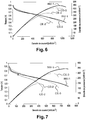
- the figure 6 represents the polarization curve and the power density curve as a function of the current density.
- the three AME assemblies are subjected to 30,000 cycles between 0.6 and 1 V under H 2 / N 2 at the anode and the cathode respectively. These conditions make it possible to carry out accelerated aging tests.
- the figure 7 represents the polarization and power density curves as a function of the current density. These curves were obtained after 30,000 cycles of aging. These curves show that the use of the catalyst supported according to the invention (INV-1) at the cathode has a better durability. Indeed, after the 30,000 cycles, the maximum power loss is 24% for the catalyst supported according to the invention (INV-1) against 30% for the supported catalyst that has not undergone any heat treatment or surface modification. (CE-3), and 43% for the supported catalyst which has not undergone a heat treatment, but comprising PBI (CE-2).
- STEM images of Figures 8 and 9 clearly illustrate that the size of the nanoparticles is greater in the case of the supported catalyst that has not undergone heat treatment, but comprising PBI (CE-2).
- the heat treatment coupled with a modification of the surface by PBI of the carbon support makes it possible to increase the performance and the durability of the MEA.
Landscapes
- Chemical & Material Sciences (AREA)
- Engineering & Computer Science (AREA)
- Materials Engineering (AREA)
- Chemical Kinetics & Catalysis (AREA)
- Electrochemistry (AREA)
- General Chemical & Material Sciences (AREA)
- Metallurgy (AREA)
- Organic Chemistry (AREA)
- Inorganic Chemistry (AREA)
- Inert Electrodes (AREA)
- Catalysts (AREA)
Applications Claiming Priority (1)
| Application Number | Priority Date | Filing Date | Title |
|---|---|---|---|
| FR1659670A FR3057181B1 (fr) | 2016-10-07 | 2016-10-07 | Procede de preparation d'un catalyseur supporte par un materiau carbone modifie avec du polybenzimidazole |
Publications (1)
| Publication Number | Publication Date |
|---|---|
| EP3306717A1 true EP3306717A1 (de) | 2018-04-11 |
Family
ID=57349049
Family Applications (1)
| Application Number | Title | Priority Date | Filing Date |
|---|---|---|---|
| EP17193718.8A Withdrawn EP3306717A1 (de) | 2016-10-07 | 2017-09-28 | Verfahren zur vorbereitung eines katalysators mit einem träger aus polybenzimidazol-modifiziertem kohlenstoffmaterial |
Country Status (2)
| Country | Link |
|---|---|
| EP (1) | EP3306717A1 (de) |
| FR (1) | FR3057181B1 (de) |
Cited By (2)
| Publication number | Priority date | Publication date | Assignee | Title |
|---|---|---|---|---|
| CN115746524A (zh) * | 2022-11-24 | 2023-03-07 | 扬州惠通新材料有限公司 | 一种生物降解的微发泡聚乳酸材料的制备方法 |
| CN116598521A (zh) * | 2023-07-18 | 2023-08-15 | 海卓动力(青岛)能源科技有限公司 | 一种燃料电池催化剂和膜电极及其制备方法 |
Citations (3)
| Publication number | Priority date | Publication date | Assignee | Title |
|---|---|---|---|---|
| US20060110632A1 (en) * | 2004-11-20 | 2006-05-25 | Samsung Sdi Co., Ltd. | Method for preparing metal catalyst and electrode |
| US20120156589A1 (en) * | 2010-12-15 | 2012-06-21 | Samsung Electronics Co., Ltd. | Electrode catalyst for fuel cell, manufacturing method thereof, and fuel cell using the same |
| EP2811563A1 (de) | 2012-02-02 | 2014-12-10 | Kyushu University, National University Corporation | Katalysatorschichtbildender körper und verfahren zur herstellung des katalysatorschichtbildenden körpers |
-
2016
- 2016-10-07 FR FR1659670A patent/FR3057181B1/fr active Active
-
2017
- 2017-09-28 EP EP17193718.8A patent/EP3306717A1/de not_active Withdrawn
Patent Citations (3)
| Publication number | Priority date | Publication date | Assignee | Title |
|---|---|---|---|---|
| US20060110632A1 (en) * | 2004-11-20 | 2006-05-25 | Samsung Sdi Co., Ltd. | Method for preparing metal catalyst and electrode |
| US20120156589A1 (en) * | 2010-12-15 | 2012-06-21 | Samsung Electronics Co., Ltd. | Electrode catalyst for fuel cell, manufacturing method thereof, and fuel cell using the same |
| EP2811563A1 (de) | 2012-02-02 | 2014-12-10 | Kyushu University, National University Corporation | Katalysatorschichtbildender körper und verfahren zur herstellung des katalysatorschichtbildenden körpers |
Non-Patent Citations (1)
| Title |
|---|
| FUJIGAYA T ET AL: "Design of an assembly of pyridine-containing polybenzimidazole, carbon nanotubes and Pt nanoparticles for a fuel cell electrocatalyst with a high electrochemically active surface area", CARBON, ELSEVIER, OXFORD, GB, vol. 47, no. 14, 18 July 2009 (2009-07-18), pages 3227 - 3232, XP026575030, ISSN: 0008-6223, [retrieved on 20090718], DOI: 10.1016/J.CARBON.2009.07.038 * |
Cited By (4)
| Publication number | Priority date | Publication date | Assignee | Title |
|---|---|---|---|---|
| CN115746524A (zh) * | 2022-11-24 | 2023-03-07 | 扬州惠通新材料有限公司 | 一种生物降解的微发泡聚乳酸材料的制备方法 |
| CN115746524B (zh) * | 2022-11-24 | 2023-12-19 | 扬州惠通新材料有限公司 | 一种生物降解的微发泡聚乳酸材料的制备方法 |
| CN116598521A (zh) * | 2023-07-18 | 2023-08-15 | 海卓动力(青岛)能源科技有限公司 | 一种燃料电池催化剂和膜电极及其制备方法 |
| CN116598521B (zh) * | 2023-07-18 | 2023-10-03 | 海卓动力(青岛)能源科技有限公司 | 一种燃料电池催化剂和膜电极及其制备方法 |
Also Published As
| Publication number | Publication date |
|---|---|
| FR3057181B1 (fr) | 2018-10-12 |
| FR3057181A1 (fr) | 2018-04-13 |
Similar Documents
| Publication | Publication Date | Title |
|---|---|---|
| US9997788B2 (en) | Methods of producing porous platinum-based catalysts for oxygen reduction | |
| US20210143443A1 (en) | Use Of Anode Catalyst Layer | |
| US7642217B2 (en) | Pt/Ru alloy catalyst for fuel cell | |
| FR3041163A1 (fr) | Catalyseur hybride de type p/metal-n-c | |
| US11772084B2 (en) | Catalyst, liquid composition, electrode, catalyst electrode for electrochemical reaction, fuel cell, and air battery | |
| FR3035800B1 (fr) | Catalyseur supporte par des nanotubes de carbone et par du graphene, et son procede de preparation | |
| EP2880202B1 (de) | Kompositelektroden für wasserelektrolyse | |
| FR2755542A1 (fr) | Electrodes de diffusion gazeuse a base de melanges polyethersulfone et carbone | |
| KR20140075918A (ko) | 입방형 Pt/C 촉매의 제조 방법, 이로부터 제조된 입방형 Pt/C 촉매 및 이를 이용한 연료전지 | |
| EP2680353B1 (de) | Hohle Platin-Nanopartikel für Brennstoffzellen | |
| EP2559085B1 (de) | Elektrodenstruktur für protonenaustauschmembran-brennstoffzellen | |
| JP4987857B2 (ja) | 重合体分散物及び電気触媒インク | |
| EP3306717A1 (de) | Verfahren zur vorbereitung eines katalysators mit einem träger aus polybenzimidazol-modifiziertem kohlenstoffmaterial | |
| WO2011136186A1 (ja) | 電極材料 | |
| JP2009181889A (ja) | ポーラス型酵素電極の製造方法 | |
| Podleschny et al. | Investigation of carbon nanofiber‐supported electrocatalysts with ultra‐low platinum loading for the use in PEM fuel cells | |
| KR20120061484A (ko) | 연료전지 전극용 소수성 고분자-탄소지지체 복합체의 제조방법 | |
| Johnston et al. | Se-modified Ru nanoparticles as ORR catalysts–Part 1: Synthesis and analysis by RRDE and in PEFCs | |
| JP2006179427A (ja) | 燃料電池用電極触媒及び燃料電池 | |
| JP3049267B2 (ja) | 高分子膜型燃料電池用の組成物、電極及び接合体 | |
| JP5488486B2 (ja) | 触媒合剤の製造方法 | |
| Castanheira | Corrosion of high surface area carbon supports used in proton-exchange membrane fuel cell electrodes | |
| FR2985860A1 (fr) | Procede de preparation d'une membrane echangeuse de protons pour pile a combustible | |
| JP2021015723A (ja) | 白金コアシェル触媒、その製造方法、及び検査方法 | |
| Mikkelsen | Block copolymer templated bimetallic nanoparticles for fuel cell applications |
Legal Events
| Date | Code | Title | Description |
|---|---|---|---|
| PUAI | Public reference made under article 153(3) epc to a published international application that has entered the european phase |
Free format text: ORIGINAL CODE: 0009012 |
|
| STAA | Information on the status of an ep patent application or granted ep patent |
Free format text: STATUS: THE APPLICATION HAS BEEN PUBLISHED |
|
| AK | Designated contracting states |
Kind code of ref document: A1 Designated state(s): AL AT BE BG CH CY CZ DE DK EE ES FI FR GB GR HR HU IE IS IT LI LT LU LV MC MK MT NL NO PL PT RO RS SE SI SK SM TR |
|
| AX | Request for extension of the european patent |
Extension state: BA ME |
|
| STAA | Information on the status of an ep patent application or granted ep patent |
Free format text: STATUS: REQUEST FOR EXAMINATION WAS MADE |
|
| 17P | Request for examination filed |
Effective date: 20180417 |
|
| RBV | Designated contracting states (corrected) |
Designated state(s): AL AT BE BG CH CY CZ DE DK EE ES FI FR GB GR HR HU IE IS IT LI LT LU LV MC MK MT NL NO PL PT RO RS SE SI SK SM TR |
|
| GRAP | Despatch of communication of intention to grant a patent |
Free format text: ORIGINAL CODE: EPIDOSNIGR1 |
|
| STAA | Information on the status of an ep patent application or granted ep patent |
Free format text: STATUS: GRANT OF PATENT IS INTENDED |
|
| RIC1 | Information provided on ipc code assigned before grant |
Ipc: C25B 11/04 20060101ALI20180912BHEP Ipc: H01M 4/92 20060101ALI20180912BHEP Ipc: C25B 1/04 20060101AFI20180912BHEP |
|
| INTG | Intention to grant announced |
Effective date: 20181012 |
|
| STAA | Information on the status of an ep patent application or granted ep patent |
Free format text: STATUS: THE APPLICATION IS DEEMED TO BE WITHDRAWN |
|
| 18D | Application deemed to be withdrawn |
Effective date: 20190223 |