EP3306283A1 - Load measuring device for construction machine - Google Patents
Load measuring device for construction machine Download PDFInfo
- Publication number
- EP3306283A1 EP3306283A1 EP15893289.7A EP15893289A EP3306283A1 EP 3306283 A1 EP3306283 A1 EP 3306283A1 EP 15893289 A EP15893289 A EP 15893289A EP 3306283 A1 EP3306283 A1 EP 3306283A1
- Authority
- EP
- European Patent Office
- Prior art keywords
- load
- loading weight
- suspension
- suspension cylinders
- measuring apparatus
- Prior art date
- Legal status (The legal status is an assumption and is not a legal conclusion. Google has not performed a legal analysis and makes no representation as to the accuracy of the status listed.)
- Granted
Links
Images



Classifications
-
- G—PHYSICS
- G01—MEASURING; TESTING
- G01G—WEIGHING
- G01G19/00—Weighing apparatus or methods adapted for special purposes not provided for in the preceding groups
- G01G19/08—Weighing apparatus or methods adapted for special purposes not provided for in the preceding groups for incorporation in vehicles
- G01G19/10—Weighing apparatus or methods adapted for special purposes not provided for in the preceding groups for incorporation in vehicles having fluid weight-sensitive devices
-
- B—PERFORMING OPERATIONS; TRANSPORTING
- B60—VEHICLES IN GENERAL
- B60G—VEHICLE SUSPENSION ARRANGEMENTS
- B60G13/00—Resilient suspensions characterised by arrangement, location or type of vibration dampers
- B60G13/02—Resilient suspensions characterised by arrangement, location or type of vibration dampers having dampers dissipating energy, e.g. frictionally
- B60G13/06—Resilient suspensions characterised by arrangement, location or type of vibration dampers having dampers dissipating energy, e.g. frictionally of fluid type
-
- B—PERFORMING OPERATIONS; TRANSPORTING
- B60—VEHICLES IN GENERAL
- B60G—VEHICLE SUSPENSION ARRANGEMENTS
- B60G17/00—Resilient suspensions having means for adjusting the spring or vibration-damper characteristics, for regulating the distance between a supporting surface and a sprung part of vehicle or for locking suspension during use to meet varying vehicular or surface conditions, e.g. due to speed or load
- B60G17/015—Resilient suspensions having means for adjusting the spring or vibration-damper characteristics, for regulating the distance between a supporting surface and a sprung part of vehicle or for locking suspension during use to meet varying vehicular or surface conditions, e.g. due to speed or load the regulating means comprising electric or electronic elements
- B60G17/018—Resilient suspensions having means for adjusting the spring or vibration-damper characteristics, for regulating the distance between a supporting surface and a sprung part of vehicle or for locking suspension during use to meet varying vehicular or surface conditions, e.g. due to speed or load the regulating means comprising electric or electronic elements characterised by the use of a specific signal treatment or control method
- B60G17/0182—Resilient suspensions having means for adjusting the spring or vibration-damper characteristics, for regulating the distance between a supporting surface and a sprung part of vehicle or for locking suspension during use to meet varying vehicular or surface conditions, e.g. due to speed or load the regulating means comprising electric or electronic elements characterised by the use of a specific signal treatment or control method involving parameter estimation, e.g. observer, Kalman filter
-
- G—PHYSICS
- G01—MEASURING; TESTING
- G01G—WEIGHING
- G01G19/00—Weighing apparatus or methods adapted for special purposes not provided for in the preceding groups
- G01G19/02—Weighing apparatus or methods adapted for special purposes not provided for in the preceding groups for weighing wheeled or rolling bodies, e.g. vehicles
- G01G19/028—Weighing apparatus or methods adapted for special purposes not provided for in the preceding groups for weighing wheeled or rolling bodies, e.g. vehicles combined with shock-absorbing devices
-
- G—PHYSICS
- G01—MEASURING; TESTING
- G01G—WEIGHING
- G01G19/00—Weighing apparatus or methods adapted for special purposes not provided for in the preceding groups
- G01G19/14—Weighing apparatus or methods adapted for special purposes not provided for in the preceding groups for weighing suspended loads
-
- B—PERFORMING OPERATIONS; TRANSPORTING
- B60—VEHICLES IN GENERAL
- B60G—VEHICLE SUSPENSION ARRANGEMENTS
- B60G2300/00—Indexing codes relating to the type of vehicle
- B60G2300/02—Trucks; Load vehicles
-
- B—PERFORMING OPERATIONS; TRANSPORTING
- B60—VEHICLES IN GENERAL
- B60G—VEHICLE SUSPENSION ARRANGEMENTS
- B60G2300/00—Indexing codes relating to the type of vehicle
- B60G2300/09—Construction vehicles, e.g. graders, excavators
-
- B—PERFORMING OPERATIONS; TRANSPORTING
- B60—VEHICLES IN GENERAL
- B60G—VEHICLE SUSPENSION ARRANGEMENTS
- B60G2400/00—Indexing codes relating to detected, measured or calculated conditions or factors
- B60G2400/05—Attitude
- B60G2400/051—Angle
- B60G2400/0512—Pitch angle
-
- B—PERFORMING OPERATIONS; TRANSPORTING
- B60—VEHICLES IN GENERAL
- B60G—VEHICLE SUSPENSION ARRANGEMENTS
- B60G2400/00—Indexing codes relating to detected, measured or calculated conditions or factors
- B60G2400/20—Speed
- B60G2400/204—Vehicle speed
-
- B—PERFORMING OPERATIONS; TRANSPORTING
- B60—VEHICLES IN GENERAL
- B60G—VEHICLE SUSPENSION ARRANGEMENTS
- B60G2400/00—Indexing codes relating to detected, measured or calculated conditions or factors
- B60G2400/20—Speed
- B60G2400/208—Speed of wheel rotation
-
- B—PERFORMING OPERATIONS; TRANSPORTING
- B60—VEHICLES IN GENERAL
- B60G—VEHICLE SUSPENSION ARRANGEMENTS
- B60G2400/00—Indexing codes relating to detected, measured or calculated conditions or factors
- B60G2400/25—Stroke; Height; Displacement
- B60G2400/252—Stroke; Height; Displacement vertical
-
- B—PERFORMING OPERATIONS; TRANSPORTING
- B60—VEHICLES IN GENERAL
- B60G—VEHICLE SUSPENSION ARRANGEMENTS
- B60G2400/00—Indexing codes relating to detected, measured or calculated conditions or factors
- B60G2400/50—Pressure
- B60G2400/51—Pressure in suspension unit
-
- B—PERFORMING OPERATIONS; TRANSPORTING
- B60—VEHICLES IN GENERAL
- B60G—VEHICLE SUSPENSION ARRANGEMENTS
- B60G2400/00—Indexing codes relating to detected, measured or calculated conditions or factors
- B60G2400/50—Pressure
- B60G2400/51—Pressure in suspension unit
- B60G2400/518—Pressure in suspension unit in damper
- B60G2400/5182—Fluid damper
-
- B—PERFORMING OPERATIONS; TRANSPORTING
- B60—VEHICLES IN GENERAL
- B60G—VEHICLE SUSPENSION ARRANGEMENTS
- B60G2400/00—Indexing codes relating to detected, measured or calculated conditions or factors
- B60G2400/60—Load
-
- B—PERFORMING OPERATIONS; TRANSPORTING
- B60—VEHICLES IN GENERAL
- B60G—VEHICLE SUSPENSION ARRANGEMENTS
- B60G2800/00—Indexing codes relating to the type of movement or to the condition of the vehicle and to the end result to be achieved by the control action
- B60G2800/70—Estimating or calculating vehicle parameters or state variables
-
- B—PERFORMING OPERATIONS; TRANSPORTING
- B60—VEHICLES IN GENERAL
- B60P—VEHICLES ADAPTED FOR LOAD TRANSPORTATION OR TO TRANSPORT, TO CARRY, OR TO COMPRISE SPECIAL LOADS OR OBJECTS
- B60P1/00—Vehicles predominantly for transporting loads and modified to facilitate loading, consolidating the load, or unloading
- B60P1/04—Vehicles predominantly for transporting loads and modified to facilitate loading, consolidating the load, or unloading with a tipping movement of load-transporting element
Definitions
- the present invention relates to a load measuring apparatus for a construction machine for enhancing load measurement precision of a construction machine such as a dump truck.
- a load measuring apparatus for preventing an overload and for grasping production amount in a field and others is mounted in a dump truck that operates in a mine, a quarry and others.
- This load measuring apparatus measures a load on the basis of pressure applied to plural (normally, total four in the front-right, the front-left, the rear-right, the rear-left of a vehicle body) suspensions that support the vehicle body, the load measuring apparatus records and displays measured values at any time as disclosed in the following patent literature 1, for example.
- an oil content called silicone oil and nitrogen gas are sealed inside.
- predetermined internal pressure gas charge set pressure
- pressure in the suspension cylinder is sometimes turned below the predetermined gas charge set pressure because of running on of a vehicle body, inappropriate maintenance and others. In such a state, longitudinal and lateral balance of the vehicle body is turned unstable and an error of load measurement increases.
- an object of the present invention is to provide a new load measuring apparatus for a construction machine that enables enhancing measurement precision of a loading weight by considering a condition of a suspension cylinder.
- a first feature of the present invention is based upon a load measuring apparatus for a construction machine having a loading weight arithmetic module calculating a loading weight on the basis of loads of a plurality of suspension cylinders.
- the load measuring apparatus is provided with a loading weight confirmation module outputting the loading weight calculated by the loading weight arithmetic module when all of the loads of the suspension cylinders are equal to or larger than a specified value, the loading weight confirmation module making the loading weight calculated by the loading weight arithmetic module ineffective without outputting the loading weight when any one of the loads of the suspension cylinders is below the specified value.
- a loading weight confirmation module judges that longitudinal and lateral balance of a vehicle body is unsatisfactory when any one of loads of each suspension cylinder is below the specified value and makes a loading weight calculated by the loading weight arithmetic module ineffective without outputting the loading weight, measurement having a large error can be avoided.
- measurement precision of the loading weight can be enhanced.
- a second feature of the present invention based upon the first feature relates to the load measuring apparatus for a construction machine having a characteristic that a load of each suspension cylinder is calculated on the basis of a pressure applied to an inside of the each suspension cylinder.
- the loading weight confirmation module can make a loading weight ineffective without outputting the loading weight calculated by the loading weight arithmetic module.
- a third feature of the present invention based upon the second feature relates to the load measuring apparatus for a construction machine having a characteristic that the pressure applied to the each suspension cylinder is a pressure of a fluid sealed in the suspension cylinder.
- the loading weight confirmation module can make a loading weight ineffective without outputting the loading weight calculated by the loading weight arithmetic module.
- a fourth feature of the present invention based upon the first feature relates to the load measuring apparatus for a construction machine having a characteristic that a load of each suspension cylinder is calculated on the basis of a stroke of the each suspension cylinder.
- the loading weight confirmation module can make a loading weight ineffective without outputting the loading weight calculated by the loading weight arithmetic module.
- a fifth feature of the present invention based upon any of the first to fourth features relates to the load measuring apparatus for a construction machine having a characteristic that the specified value for the loads of the suspension cylinders are different between for front-wheel side suspension cylinders and for rear-wheel side suspension cylinders. Normally, loads applied to the front-wheel side suspension cylinders and the rear-wheel side suspension cylinders are often different from each other because of structure of the dump truck. According to such configuration, optimum output according to each suspension cylinder or invalidation can be judged.
- a sixth feature of the present invention based upon any of the first to fourth features relates to the load measuring apparatus for a construction machine having a characteristic that the specified value for the loads of the suspension cylinders are different among each of front, rear, left, and right suspension cylinders. Normally, loads applied to respective suspension cylinders may be different from each other because of the structure of the dump truck. According to such configuration, optimum output according to each suspension cylinder or invalidation can be judged.
- Figs. 1 to 5 show one embodiment of a load measuring apparatus 100 for a construction machine according to the present invention.
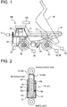
- Fig. 1 is a side view showing a dump truck 200 as one example of a construction machine to which the load measuring apparatus 100 according to the present invention is applied
- Fig. 2 is a longitudinal section view showing simplified structure of suspension cylinders 51, 61 provided to the dump truck 200
- Fig. 3 is a block diagram showing the load measuring apparatus 100 according to the present invention
- Fig. 4 is similarly a functional block diagram showing the load measuring apparatus 100 according to the present invention
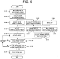
- Fig. 5 is similarly a flowchart showing a process of the load measuring apparatus 100 according to the present invention.
- the dump truck 200 to which the load measuring apparatus 100 according to the present invention is applied is provided with a vehicle body 10, an operator cab 20 provided to the front of the vehicle body 10, a vessel 30 onto which a load such as earth, sand and crushed stone is loaded, a vessel operating cylinder 40 for vertically turning the vessel 30 as shown by a dash-dotted line, front wheels 50 (the other is not shown) arranged on the right and left sides of the front side of the vehicle body 10, suspension cylinders 51 (the other is not shown) on the right and left sides of the front side for supporting front wheels 50,50, respectively, rear wheels 60 (the other is not shown) arranged on the right and left sides of the rear side of the vehicle body 10 and suspension cylinders 61 (the other is not shown) on the right and left sides of the rear side for supporting rear wheels 60, 60, respectively as shown in Fig. 1 .
- Some dump trucks may be provided with total four rear wheels 60 (pairs of two) on the right and left sides of the rear side of the vehicle body 10.
- a tilt sensor 70 that senses a tilt angle in a longitudinal direction of the vehicle body 10 is provided.
- rear wheel speed detectors 80, 80 that detect rotational speed of the rear wheels are provided to the right and left rear wheels 60, 60, respectively, and further, a vehicle speed detector 90 that detects speed of the vehicle body 10 is provided to the vehicle body 10.
- Pressure sensors 52, 52, 62, 62 are attached to the four suspension cylinders 51, 51, 61, 61 arranged in longitudinal and lateral directions of the vehicle body 10, for sensing loads applied to the respective cylinders, as equipment for measuring weight of a load as shown in Fig. 2 .
- each of the suspension cylinders 51, 51, 61, 61 is provided with a cylinder 54 that supports the side of wheels 50, 50, 60, 60 and a piston 55 that supports the side of the vehicle body 10.
- the piston 55 is provided with a piston body 55a vertically sliding in the cylinder 54 and a piston tube 55b coupled to the piston body 55a.
- the cylinder 54 is partitioned into a head chamber 56 and a bottom chamber 57 by the piston body 55a so that oil flows between the head chamber 56 and the bottom chamber 57 via an orifice 55c formed through the piston body 55a.
- Nitrogen gas is sealed together with the oil in the piston tube 55b communicating with the bottom chamber 57 and pressure of the nitrogen gas is measured by a gas pressure sensor 53 provided to the piston tube 55b at any time. Measurement signals from these sensors 52, 53, 62, 70 are inputted to the load measuring apparatus 100 according to the present invention as shown in Fig. 3 .
- Fig. 3 shows hardware configuration of the load measuring apparatus 100 according to the present invention.
- a detection signal from the tilt sensor 70 that senses a tilt angle in the longitudinal direction of the vehicle body 10
- a detection signal from the vehicle speed detector 90 that detects the speed of the vehicle body 10
- detection signals from the rear wheel speed detectors 80, 80 that detect rotational speeds of the respective right and left rear wheels 60, 60
- detection signals from the pressure sensors 52, 52, 62, 62 that measure loads of the respective suspension cylinders 51, 51, 61, 61
- detection signals from the gas pressure sensors 53, 53, 63, 63 that measure inside gas pressures of the respective suspension cylinders 51, 51, 61, 61 are inputted to the load measuring apparatus 100.
- the load measuring apparatus 100 is provided with an arithmetic unit (CPU) 110 that calculates according to various processing programs, a timer 120 that drives the arithmetic unit 110, a clock 130 for acquiring time, a read only memory (ROM) 140 that stores various processing programs, a random access memory (RAM) 150 that temporarily stores variable values and load data as a result of load measurement, an input interface 160 for input from the sensors and for communication and an output interface 170 for outputting an calculation result from the arithmetic unit 110 to a display 180 installed in the operator cab 20 and an external device (not shown) such as a control center.
- CPU arithmetic unit
- timer 120 that drives the arithmetic unit 110
- a clock 130 for acquiring time
- ROM read only memory
- RAM random access memory
- input interface 160 for input from the sensors and for communication
- an output interface 170 for outputting an calculation result from the arithmetic unit 110 to a display 180 installed in the operator cab 20 and an external device (not
- the arithmetic unit 110 of the load measuring apparatus 100 shown in Fig. 3 functions as a loading weight arithmetic module 111 for calculating a payload amount (loading amount) loaded onto the vessel 30 and a loading weight confirmation module 112 for confirming whether the payload amount (loading amount) calculated by the loading weight arithmetic module 111 is to be outputted or not according to the various processing programs stored in the ROM 14 as shown in Fig. 4 .
- the loading weight arithmetic module 111 is provided with first multipliers 11a, 11a that multiply cylinder pressures output from the pressure sensors 52, 52 for measuring each of the cylinder pressures of the front-wheel side suspension cylinders 51, 51 and the value D of the sectional area of the suspension cylinder 51 stored beforehand respectively so as to calculate loads respectively acting on the front-wheel side suspension cylinders 51, 51; second multipliers 12a, 12a that similarly multiply suspension cylinder pressures output from the pressure sensors 62, 62 for measuring each of the cylinder pressures of the rear-wheel side suspension cylinders 61, 61 and the value D of the sectional area of the suspension cylinder 62 stored beforehand respectively so as to calculate loads respectively acting on the rear-wheel side suspension cylinders 61, 61; a first adder 11c that adds respective loads of the front-wheel side suspension cylinders 51, 51 output from the first multipliers 11a, 11a so as to calculate the front side load PF acting on the front-wheel side suspension
- the loading weight confirmation module 112 is provided with a loading mass fluctuation range measuring unit 12a that samples the loading mass output from the loading weight arithmetic module 111 several times within a definite time; a loading mass fluctuation range confirmation unit 12b that calculates an average value of measured values output from the loading mass fluctuation range measuring unit 12a, and confirms that the difference between the maximum measured value and the minimum measured value is minimum for the average value; a speed difference detector 12e that calculates difference between speeds respectively from the right and left rear wheel speed detectors 62, 62 for detecting the rotational speed of the respective right/left rear wheels 60, 60; and a first confirmation arithmetic unit (a logical multiply operation unit: AND) 12c that outputs the loading mass output from the loading weight arithmetic module 111 when the following three conditions are satisfied and that makes the loading mass output from the loading weight arithmetic module 111 as an output of the final loading mass ineffective when any one of the these conditions is not satisfied.
- a loading mass fluctuation range measuring unit 12a
- the above-mentioned conditions are as follows.
- the condition 1 is a case that the vehicle speed output from the vehicle speed detector 90 is equal to or larger than a predetermined set value (for example, a few km/h) and a traveling state is so-called a load weight measurable
- the condition 2 is a case that the loading mass output from the loading mass fluctuation range confirmation unit 12b is within fluctuation
- the condition 3 is a case that the difference between speeds respectively output from the rear wheel speed detectors 62, 62 is smaller than the predetermined set value, and it is judged the dump track travels not on a so-called curved path but on a linear path.
- the loading weight confirmation module 112 is provided with a second confirmation arithmetic unit (a logical multiply operation unit: AND) 12d in addition to the first confirmation arithmetic unit 12c.
- the second confirmation arithmetic unit 12d judges gas pressures inside the respective suspension cylinders 51, 51, 61, 61 on the basis of detection values from respective gas pressure sensors 53, 53, 63, 63 provided to suspension cylinders 51, 51, 61, 61, respectively.
- the loading mass calculated in the first confirmation arithmetic unit 12c is hold and is outputted to the external display 180 as a final output, and when any of the gas pressures is below the specified value, the loading mass calculated in the first confirmation arithmetic unit 12c is made ineffective without outputting to the external display 180 as a final output.
- the present invention is not limited to the case that the specified values for judging the gas pressures of the suspension cylinders 51, 51, 61, 61 are the same (several to approximately dozen MPa), however, the specified values may be different between the front wheels and the rear wheels or every wheel.
- the first multipliers 11a, 11a and the second multipliers 11b, 11b of the loading weight arithmetic module 111 measure respective cylinder pressures of the suspension cylinders 51, 51 on the front wheels 50, 50 sides and the suspension cylinders 61, 61 on the rear wheels 60, 60 sides obtained from the pressure sensors 52, 52, 62, 62 and a process flow proceeds to the next step S102.
- step S102 respective cylinder pressures and the values D of the sectional areas of respective suspension cylinders 51, 51, 61, 61 stored beforehand are respectively multiplied so as to calculate the loads acting on the suspension cylinders 51, 51, 61, 61 respectively, and the process flow proceeds to the next step s204.
- loads of the front-wheel side suspension cylinders 51, 51 output from the first multipliers 11a, 11a are added by the first adder 11c so as to calculate the front side load PF that acts on the front-wheel side suspension cylinders.
- the second adder 11d similarly calculates the rear side load PR that acts on the rear-wheel side suspension cylinders 61, 61 on the basis of loads output from the second multipliers 11b, 11b.
- the third adder 11e adds the front side load PF output from the first adder 11c and the rear side load PR output from the second adder 11d so as to calculate the total load Pt of the suspension cylinders 51, 51, 61, 61.
- a tilt angle ⁇ is calculated on the basis of a signal from the tilt sensor 70 and the process flow proceeds to the step S110.
- a correction amount of weight is calculated. That is, the total load correction arithmetic unit 11f calculates a corrected total load Pt when the vehicle body 10 is not tilted from the total load Pt output from the third adder 11e of the suspension cylinders 51, 61 on the basis of the tilt angle ⁇ and the total load Pt correction characteristic A stored beforehand. Also, the front/rear load ratio correction arithmetic unit 11h calculates a corrected front/rear load ratio X when the vehicle body 10 is not tilted from the front/rear load ratio Xt output from the first divider 11g on the basis of the tilt angle ⁇ from the tilt sensor 70 and the front/rear load ratio X correction characteristic B stored beforehand.
- the total load correction ratio arithmetic unit 11j calculates loading eccentricity correction ratio Xa of the total load Pt on the basis of the corrected front/rear load ratio X output from the front/rear load ratio correction arithmetic unit 11h and the total load Pt correction ratio characteristic C of the loading eccentricity correction ratio. Also, the second divider 11k divides the corrected total load Pt output from the total load correction arithmetic unit 11f by the loading eccentricity correction ratio Y of the total load Pt output from the total load correction ratio arithmetic unit 11j. At this time, the second divider 11k takes the vehicle speed signal, and the second divider 11k does not execute these processes when it is determined that the vehicle body stops, these processing is not executed.
- the subtracter 11n subtracts a frame mass of the vehicle body 10 side supported by the front-wheel side suspension cylinders 51, 51 and the rear-wheel side suspension cylinders 61, 61 from the total load Pt output from the third multiplier 11m so as to calculate the loading mass, and the process flow proceeds to the next step S116.
- the loading mass fluctuation range measuring unit 12a in the loading weight confirmation module 112 samples the loading mass output from the loading weight arithmetic module 111 several times within a definite time.
- the loading mass fluctuation range confirmation unit 12b calculates the average value of measured values output from the loading mass fluctuation range measuring unit 12a, confirms that the difference between the maximum measured value and the minimum measured value is minimum for the average value, and the process flow proceeds to a step S120.
- the speed difference detector 12e calculates difference between each of the speeds from the rear wheel speed detectors 62, 62.
- the first confirmation arithmetic unit 12c outputs the loading mass output from the loading weight arithmetic module 111 as a payload when the following three conditions are met (YES) and the process flow proceeds to the next step S122.
- the above-mentioned three conditions are as follows.
- the condition 1 is that the vehicle speed output from the vehicle speed detector 90 is equal to or larger than a predetermined set value (for example, a few km/h) and a traveling state is so-called a load weight measurable
- the condition 2 is a case that the loading mass output from the loading mass fluctuation range confirmation unit 12b is within fluctuation
- the condition 3 is a case that the difference between speeds respectively output from the rear wheel speed detectors 62, 62 is smaller than the predetermined set value, and it is judged the dump track travels not on a so-called curved path but on a linear path.
- the first confirmation arithmetic unit 12c makes the output of loading mass from the loading weight arithmetic module 111 ineffective and the process flow proceeds to the step S116.
- the second confirmation arithmetic unit 12d judges whether all of the gas pressures of the suspension cylinders 51, 51, 61, 61 exceed the specified value on the basis of measured values output from the gas pressure sensors 53, 53, 63, 63 or not.
- the second confirmation arithmetic unit 12d judges that all of the gas pressures exceed the specified value (YES)
- the loading mass output from the first confirmation arithmetic unit 12c is outputted as a payload and the process flow proceeds to the next step S124, however, when the second confirmation arithmetic unit 12d judges that any one is smaller than the specified value (NO), the loading mass output from the first confirmation arithmetic unit 12c is made ineffective, and the process flow is returned to the step S116.
- step S124 the loading mass acquired from the loading weight arithmetic module 111 in a state in which all of the these conditions 1 to 4 are satisfied is held and output, and the loading mass is displayed on the display 180.
- the present invention not only when the conditions for the traveling path of the dump truck 200 and the fluctuation of the loading mass are satisfied, but also when any one of gas charge set pressure of respective suspension cylinders 51, 51, 61, 61 is below the specified value, it is judged that the longitudinal and lateral balance of the vehicle body is unsatisfactory so that the loading mass calculated by the loading weight arithmetic module 111 is made ineffective without outputting. Therefore, a situation that a measured value having a large error is held and displayed can be avoided. Hereby, as only a precise measured value is outputted, measuring precision can be more enhanced.
- the second confirmation arithmetic unit 12d judges whether all of the gas pressures of the suspension cylinders satisfy the specified value (the condition 4) or not.
- the condition 4 is judged in advance and when the condition 4 is satisfied, it may be also judged whether the conditions 1 to 3 are met or not.
- the judgment can be made at a timing not only immediately before the first confirmation arithmetic unit 12c but at an earlier stage, for example, immediately after the step S100.
- a stroke sensor 58 that measures stroke width (extended or contracted quantity) of the suspension cylinders 51, 51, 61, 61 may be also provided in place of the gas pressure sensors 53, 53, 63, 63 of the suspension cylinders 51, 51, 61, 61 or together with the gas pressure sensors 53, 53, 63, 63.
- the extended or contracted quantity of any of the suspension cylinders 51, 51, 61, 61 is extremely large, it can be also judged that the longitudinal and lateral balance of the vehicle body is unstable. In this case, as shown in Figs.
Landscapes
- Physics & Mathematics (AREA)
- General Physics & Mathematics (AREA)
- Engineering & Computer Science (AREA)
- Mechanical Engineering (AREA)
- Vehicle Body Suspensions (AREA)
Abstract
Description
- The present invention relates to a load measuring apparatus for a construction machine for enhancing load measurement precision of a construction machine such as a dump truck.
- A load measuring apparatus for preventing an overload and for grasping production amount in a field and others is mounted in a dump truck that operates in a mine, a quarry and others. This load measuring apparatus measures a load on the basis of pressure applied to plural (normally, total four in the front-right, the front-left, the rear-right, the rear-left of a vehicle body) suspensions that support the vehicle body, the load measuring apparatus records and displays measured values at any time as disclosed in the following
patent literature 1, for example. - In such a load measuring apparatus, it greatly depends upon a traveling path whether a state suitable for measuring a load is acquired in normal loaded traveling or not. For example, in a case seen in a quarry by cutting through a mountain that crushed stone is loaded on the upside of the mountain and a dump truck descends on a slope as it is, precise load measurement cannot be made because a traveling road has no flat location. Therefore, in the following patent literature 2, for example, a device that measures a load and records a measured value at timing hardly having the effect of a traveling state and a state of the ground, for example, during backward travel when a dump truck discharges soils is disclosed.
- Besides, as disclosed in the following
patent literature 3, technique for equalizing pressure of each suspension so as to inhibit the effect of a jolt in traveling and frictional resistance of suspension cylinders is also proposed. Further, as disclosed in the following patent literature 4, as lateral balance is often lost when the dump truck travels on a curved path, technique that enhances measurement precision by inhibiting load measurement in such a case is also proposed. -
- PATENT LITERATURE 1:
JP-A No. 2007-298449 - PATENT LITERATURE 2:
JP-A No. 2005-43267 - PATENT LITERATURE 3:
JP-A No. 1985-161532 - PATENT LITERATURE 4: Japanese Patent No.
5160468 - Incidentally, in four suspension cylinders used for the above-mentioned conventional type load measuring apparatuses, an oil content called silicone oil and nitrogen gas are sealed inside. As for pressure in such the suspension cylinder, predetermined internal pressure (gas charge set pressure) is normally applied, however, pressure in the suspension cylinder is sometimes turned below the predetermined gas charge set pressure because of running on of a vehicle body, inappropriate maintenance and others. In such a state, longitudinal and lateral balance of the vehicle body is turned unstable and an error of load measurement increases.
- Besides, even if gas charge set pressure of all the suspension cylinders is kept at gas charge set pressure of a specified value, load balance is turned unstable depending upon posture in loading so that a load may be received by only three or two out of the four suspension cylinders, it cannot be judged that a load is uniformly applied to all the suspension cylinders.
- Then, the present invention is made so as to settle these problems and an object of the present invention is to provide a new load measuring apparatus for a construction machine that enables enhancing measurement precision of a loading weight by considering a condition of a suspension cylinder.
- To achieve the object, a first feature of the present invention is based upon a load measuring apparatus for a construction machine having a loading weight arithmetic module calculating a loading weight on the basis of loads of a plurality of suspension cylinders. The load measuring apparatus is provided with a loading weight confirmation module outputting the loading weight calculated by the loading weight arithmetic module when all of the loads of the suspension cylinders are equal to or larger than a specified value, the loading weight confirmation module making the loading weight calculated by the loading weight arithmetic module ineffective without outputting the loading weight when any one of the loads of the suspension cylinders is below the specified value.
- According to such configuration, as a loading weight confirmation module judges that longitudinal and lateral balance of a vehicle body is unsatisfactory when any one of loads of each suspension cylinder is below the specified value and makes a loading weight calculated by the loading weight arithmetic module ineffective without outputting the loading weight, measurement having a large error can be avoided. Hereby, as only a precise measured value is outputted, measurement precision of the loading weight can be enhanced.
- A second feature of the present invention based upon the first feature relates to the load measuring apparatus for a construction machine having a characteristic that a load of each suspension cylinder is calculated on the basis of a pressure applied to an inside of the each suspension cylinder. According to such configuration, when pressure applied to the inside of the suspension cylinder is turned equal to or less than the specified pressure because of running on of the vehicle body, inappropriate maintenance or the like, the loading weight confirmation module can make a loading weight ineffective without outputting the loading weight calculated by the loading weight arithmetic module.
- A third feature of the present invention based upon the second feature relates to the load measuring apparatus for a construction machine having a characteristic that the pressure applied to the each suspension cylinder is a pressure of a fluid sealed in the suspension cylinder. According to such configuration, when fluid pressure in the suspension cylinder is equal to or less than the specified pressure because of running on of the vehicle body, inappropriate maintenance or the like, the loading weight confirmation module can make a loading weight ineffective without outputting the loading weight calculated by the loading weight arithmetic module.
- A fourth feature of the present invention based upon the first feature relates to the load measuring apparatus for a construction machine having a characteristic that a load of each suspension cylinder is calculated on the basis of a stroke of the each suspension cylinder. According to such configuration, when the stroke of the suspension cylinder exceeds a specified range because of running on of the vehicle body, inappropriate maintenance or the like, the loading weight confirmation module can make a loading weight ineffective without outputting the loading weight calculated by the loading weight arithmetic module.
- A fifth feature of the present invention based upon any of the first to fourth features relates to the load measuring apparatus for a construction machine having a characteristic that the specified value for the loads of the suspension cylinders are different between for front-wheel side suspension cylinders and for rear-wheel side suspension cylinders. Normally, loads applied to the front-wheel side suspension cylinders and the rear-wheel side suspension cylinders are often different from each other because of structure of the dump truck. According to such configuration, optimum output according to each suspension cylinder or invalidation can be judged.
- A sixth feature of the present invention based upon any of the first to fourth features relates to the load measuring apparatus for a construction machine having a characteristic that the specified value for the loads of the suspension cylinders are different among each of front, rear, left, and right suspension cylinders. Normally, loads applied to respective suspension cylinders may be different from each other because of the structure of the dump truck. According to such configuration, optimum output according to each suspension cylinder or invalidation can be judged.
- According to the present invention, when any one of loads of respective suspension cylinders is less than the specified value, it is judged that longitudinal and lateral balance of the vehicle body is unsatisfactory and a loading weight calculated by the loading weight arithmetic module is made ineffective without outputting the loading weight, thereby a measurement having a large error can be avoided. Hereby, only precise measured values are outputted so that a measurement precision can be more enhanced.
-
- [
Fig. 1] Fig. 1 is a side view showing adump truck 200 as one example of a construction machine to which aload measuring apparatus 100 according to the present invention is applied. - [
Fig. 2] Fig. 2 is a longitudinal section view showing simplified structure of asuspension cylinder - [
Fig. 3] Fig. 3 is a hardware configuration diagram showing theload measuring apparatus 100 according to the present invention. - [
Fig. 4] Fig. 4 is a functional block diagram showing theload measuring apparatus 100 according to the present invention. - [
Fig. 5] Fig. 5 is a flowchart showing one example of a process flow by theload measuring apparatus 100 according to the present invention. - [
Fig. 6] Fig. 6 is a functional block diagram showing theload measuring apparatus 100 according to the present invention. - [
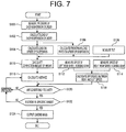
Fig. 7] Fig. 7 is a flowchart showing one example of a process flow by theload measuring apparatus 100 according to the present invention. - Next, embodiments of the present invention will be described referring to the attached drawings.
Figs. 1 to 5 show one embodiment of aload measuring apparatus 100 for a construction machine according to the present invention.Fig. 1 is a side view showing adump truck 200 as one example of a construction machine to which theload measuring apparatus 100 according to the present invention is applied,Fig. 2 is a longitudinal section view showing simplified structure ofsuspension cylinders dump truck 200,Fig. 3 is a block diagram showing theload measuring apparatus 100 according to the present invention,Fig. 4 is similarly a functional block diagram showing theload measuring apparatus 100 according to the present invention, andFig. 5 is similarly a flowchart showing a process of theload measuring apparatus 100 according to the present invention. - The
dump truck 200 to which theload measuring apparatus 100 according to the present invention is applied is provided with avehicle body 10, anoperator cab 20 provided to the front of thevehicle body 10, avessel 30 onto which a load such as earth, sand and crushed stone is loaded, avessel operating cylinder 40 for vertically turning thevessel 30 as shown by a dash-dotted line, front wheels 50 (the other is not shown) arranged on the right and left sides of the front side of thevehicle body 10, suspension cylinders 51 (the other is not shown) on the right and left sides of the front side for supportingfront wheels vehicle body 10 and suspension cylinders 61 (the other is not shown) on the right and left sides of the rear side for supportingrear wheels Fig. 1 . Some dump trucks may be provided with total four rear wheels 60 (pairs of two) on the right and left sides of the rear side of thevehicle body 10. - Moreover, in the
operator cab 20 of thevehicle body 10 as shown inFig. 1 , atilt sensor 70 that senses a tilt angle in a longitudinal direction of thevehicle body 10 is provided. In addition, rearwheel speed detectors rear wheels vehicle speed detector 90 that detects speed of thevehicle body 10 is provided to thevehicle body 10. -
Pressure sensors suspension cylinders vehicle body 10, for sensing loads applied to the respective cylinders, as equipment for measuring weight of a load as shown inFig. 2 . - As shown in
Fig. 2 , each of thesuspension cylinders cylinder 54 that supports the side ofwheels piston 55 that supports the side of thevehicle body 10. Thepiston 55 is provided with apiston body 55a vertically sliding in thecylinder 54 and apiston tube 55b coupled to thepiston body 55a. - The
cylinder 54 is partitioned into ahead chamber 56 and abottom chamber 57 by thepiston body 55a so that oil flows between thehead chamber 56 and thebottom chamber 57 via anorifice 55c formed through thepiston body 55a. Nitrogen gas is sealed together with the oil in thepiston tube 55b communicating with thebottom chamber 57 and pressure of the nitrogen gas is measured by agas pressure sensor 53 provided to thepiston tube 55b at any time. Measurement signals from thesesensors load measuring apparatus 100 according to the present invention as shown inFig. 3 . -
Fig. 3 shows hardware configuration of theload measuring apparatus 100 according to the present invention. As shown inFig. 3 , a detection signal from thetilt sensor 70 that senses a tilt angle in the longitudinal direction of thevehicle body 10, a detection signal from thevehicle speed detector 90 that detects the speed of thevehicle body 10, detection signals from the rearwheel speed detectors rear wheels pressure sensors respective suspension cylinders gas pressure sensors respective suspension cylinders load measuring apparatus 100. - The
load measuring apparatus 100 is provided with an arithmetic unit (CPU) 110 that calculates according to various processing programs, atimer 120 that drives thearithmetic unit 110, aclock 130 for acquiring time, a read only memory (ROM) 140 that stores various processing programs, a random access memory (RAM) 150 that temporarily stores variable values and load data as a result of load measurement, aninput interface 160 for input from the sensors and for communication and an output interface 170 for outputting an calculation result from thearithmetic unit 110 to adisplay 180 installed in theoperator cab 20 and an external device (not shown) such as a control center. - The ROM 140 stores a value D of a sectional area of each cylinder of the front-wheel side suspension cylinders 51, 51, and the rear-wheel side suspension cylinders 61, 61; a weight G of the vehicle body 10 side supported by each of the front-wheel side suspension cylinders 51, 51 and the rear-wheel side suspension cylinders 61, 61; a total load Pt correction characteristic A for calculating a total load Pt when no tilt is applied from a total load Pt that acts on all the suspension cylinders 51, 51, 61, 61 on the basis of a tilt angle θ of the vehicle body 10 from the tilt sensor 70; a front/rear load ratio X correction characteristic B for calculation a load ratio X when no tilt is applied from a load ratio Xt of the suspension that is a ratio of a front side load PF that acts on the front-wheel side suspension cylinders 51, 51, to a rear side load PR that acts on the rear-wheel side suspension cylinders 61, 61(Xt=PF/PR) on the basis of the tilt angle θ of the vehicle body 10 from the tilt sensor 70; and a total load Pt correction ratio characteristic C for calculating loading eccentricity correction ratio Xa of the total load Pt on the basis of the corrected front/rear load ratio X in addition to various processing programs respectively as shown in
Fig. 4 . - Next, a concrete process flow in the
load measuring apparatus 100 configured as described above according to the present invention will be described referring to the block diagram shown inFig. 3 , the functional block diagram shown inFig. 4 and the flowchart shown inFig. 5 . Thearithmetic unit 110 of theload measuring apparatus 100 shown inFig. 3 functions as a loading weightarithmetic module 111 for calculating a payload amount (loading amount) loaded onto thevessel 30 and a loadingweight confirmation module 112 for confirming whether the payload amount (loading amount) calculated by the loading weightarithmetic module 111 is to be outputted or not according to the various processing programs stored in the ROM 14 as shown inFig. 4 . - As shown in
Fig. 4 , first, the loading weight arithmetic module 111 is provided with first multipliers 11a, 11a that multiply cylinder pressures output from the pressure sensors 52, 52 for measuring each of the cylinder pressures of the front-wheel side suspension cylinders 51, 51 and the value D of the sectional area of the suspension cylinder 51 stored beforehand respectively so as to calculate loads respectively acting on the front-wheel side suspension cylinders 51, 51; second multipliers 12a, 12a that similarly multiply suspension cylinder pressures output from the pressure sensors 62, 62 for measuring each of the cylinder pressures of the rear-wheel side suspension cylinders 61, 61 and the value D of the sectional area of the suspension cylinder 62 stored beforehand respectively so as to calculate loads respectively acting on the rear-wheel side suspension cylinders 61, 61; a first adder 11c that adds respective loads of the front-wheel side suspension cylinders 51, 51 output from the first multipliers 11a, 11a so as to calculate the front side load PF acting on the front-wheel side suspension cylinders 51, 51; a second adder 11d that similarly adds respective loads of the rea-wheel side suspension cylinders 61, 61 output from the second multipliers 11b, 11b so as to calculate the rear side load PR acting on the rear-wheel side suspension cylinders 61, 61; and a third adder 11e that adds the front side load PF output from the first adder 11c and the rear side load PR output from the second adder 11d so as to calculate the total load Pt of the suspension cylinders 51, 51, 61, 61. - Further, the loading weight arithmetic module 111 is provided with a total load correction arithmetic unit 11f that calculates the total load Pt when the vehicle body 10 is not tilted from the total load Pt of the suspension cylinders 51, 51, 61, 61 output from the third adder 11e on the basis of the tilt angle θ output from the tilt sensor 70 and the total load Pt correction characteristic A stored beforehand; a first divider 11g that calculates the front/rear load ratio Xt (Xt = PF/PR) that is a ratio of the front side load PF output from the first adder 11c to the rear side load PR output from the second adder 11d; a front/rear load ratio correction arithmetic unit 11h that calculates a corrected front/rear load ratio X when the vehicle body 10 is not tilted from the front/rear load ratio Xt output from the first divider 11g on the basis of a tilt angle θ from the tilt sensor 70 and the front/rear load ratio X correction characteristic B stored beforehand; a vehicle body stop correction unit 11i that determines whether the vehicle body 10 travels or stops on the basis of a vehicle speed signal; a total load correction ratio arithmetic unit 11j that calculates loading eccentricity correction ratio Xa of the total load Pt on the basis of the corrected front/rear load ratio X output from the front/rear load ratio correction arithmetic unit 11h and the total load Pt correction ratio characteristic C of the loading eccentricity correction ratio; a second divider 11k that divides the corrected total load Pt output from the total load correction arithmetic unit 11f by the loading eccentricity correction ratio Y of the total load Pt output from the total load correction ratio arithmetic unit 11j; a third multiplier 11m that multiplies the total load Pt output from the second divider 11k by suspension load ratio; and a subtracter 11n that subtracts a frame mass upside the suspension being a weight of the vehicle body 10 side supported by the front-wheel side suspension cylinders 51, 51 and the rear-wheel side suspension cylinders 61, 61 from the total load Pt output from the third multiplier 11m so as to calculate the loading mass.
- In the meantime, the loading
weight confirmation module 112 is provided with a loading mass fluctuation range measuring unit 12a that samples the loading mass output from the loading weightarithmetic module 111 several times within a definite time; a loading mass fluctuationrange confirmation unit 12b that calculates an average value of measured values output from the loading mass fluctuation range measuring unit 12a, and confirms that the difference between the maximum measured value and the minimum measured value is minimum for the average value; aspeed difference detector 12e that calculates difference between speeds respectively from the right and left rearwheel speed detectors rear wheels arithmetic module 111 when the following three conditions are satisfied and that makes the loading mass output from the loading weightarithmetic module 111 as an output of the final loading mass ineffective when any one of the these conditions is not satisfied. The above-mentioned conditions are as follows. Thecondition 1 is a case that the vehicle speed output from thevehicle speed detector 90 is equal to or larger than a predetermined set value (for example, a few km/h) and a traveling state is so-called a load weight measurable, the condition 2 is a case that the loading mass output from the loading mass fluctuationrange confirmation unit 12b is within fluctuation, and thecondition 3 is a case that the difference between speeds respectively output from the rearwheel speed detectors - Further, the loading
weight confirmation module 112 is provided with a second confirmation arithmetic unit (a logical multiply operation unit: AND) 12d in addition to the first confirmation arithmetic unit 12c. The secondconfirmation arithmetic unit 12d judges gas pressures inside therespective suspension cylinders gas pressure sensors suspension cylinders external display 180 as a final output, and when any of the gas pressures is below the specified value, the loading mass calculated in the first confirmation arithmetic unit 12c is made ineffective without outputting to theexternal display 180 as a final output. The present invention is not limited to the case that the specified values for judging the gas pressures of thesuspension cylinders - Next, one example of processing operation of the
load measuring apparatus 100 for a construction machine according to the present invention configured as described above will be described referring to the flowchart shown inFig. 5 . When an engine switch is turned on and thisdevice 100 is activated, in a first step S100, thefirst multipliers second multipliers arithmetic module 111 measure respective cylinder pressures of thesuspension cylinders front wheels suspension cylinders rear wheels pressure sensors respective suspension cylinders suspension cylinders - In the next step S104, loads of the front-wheel
side suspension cylinders first multipliers first adder 11c so as to calculate the front side load PF that acts on the front-wheel side suspension cylinders. Also, thesecond adder 11d similarly calculates the rear side load PR that acts on the rear-wheelside suspension cylinders second multipliers third adder 11e adds the front side load PF output from thefirst adder 11c and the rear side load PR output from thesecond adder 11d so as to calculate the total load Pt of thesuspension cylinders - In parallel with the step S104, in a step S106, the front/rear load ratio Xt (Xt = PF/PR) of the front side load PF output from the
first adder 11c to the rear side load PR output from thesecond adder 11d is calculated by thefirst divider 11g and the process flow proceeds to a step S110. Similarly, in a step S108, a tilt angle θ is calculated on the basis of a signal from thetilt sensor 70 and the process flow proceeds to the step S110. - In the step S110, a correction amount of weight is calculated. That is, the total load correction
arithmetic unit 11f calculates a corrected total load Pt when thevehicle body 10 is not tilted from the total load Pt output from thethird adder 11e of thesuspension cylinders arithmetic unit 11h calculates a corrected front/rear load ratio X when thevehicle body 10 is not tilted from the front/rear load ratio Xt output from thefirst divider 11g on the basis of the tilt angle θ from thetilt sensor 70 and the front/rear load ratio X correction characteristic B stored beforehand. - The total load correction ratio
arithmetic unit 11j calculates loading eccentricity correction ratio Xa of the total load Pt on the basis of the corrected front/rear load ratio X output from the front/rear load ratio correctionarithmetic unit 11h and the total load Pt correction ratio characteristic C of the loading eccentricity correction ratio. Also, thesecond divider 11k divides the corrected total load Pt output from the total load correctionarithmetic unit 11f by the loading eccentricity correction ratio Y of the total load Pt output from the total load correction ratioarithmetic unit 11j. At this time, thesecond divider 11k takes the vehicle speed signal, and thesecond divider 11k does not execute these processes when it is determined that the vehicle body stops, these processing is not executed. Thesubtracter 11n subtracts a frame mass of thevehicle body 10 side supported by the front-wheelside suspension cylinders side suspension cylinders third multiplier 11m so as to calculate the loading mass, and the process flow proceeds to the next step S116. - Next, in the step S116, the loading mass fluctuation range measuring unit 12a in the loading
weight confirmation module 112 samples the loading mass output from the loading weightarithmetic module 111 several times within a definite time. The loading mass fluctuationrange confirmation unit 12b calculates the average value of measured values output from the loading mass fluctuation range measuring unit 12a, confirms that the difference between the maximum measured value and the minimum measured value is minimum for the average value, and the process flow proceeds to a step S120. Also, in parallel with this, in steps S112, S114, S118, thespeed difference detector 12e calculates difference between each of the speeds from the rearwheel speed detectors - In the step S120, the first confirmation arithmetic unit 12c outputs the loading mass output from the loading weight
arithmetic module 111 as a payload when the following three conditions are met (YES) and the process flow proceeds to the next step S122. The above-mentioned three conditions are as follows. Thecondition 1 is that the vehicle speed output from thevehicle speed detector 90 is equal to or larger than a predetermined set value (for example, a few km/h) and a traveling state is so-called a load weight measurable, the condition 2 is a case that the loading mass output from the loading mass fluctuationrange confirmation unit 12b is within fluctuation, and thecondition 3 is a case that the difference between speeds respectively output from the rearwheel speed detectors conditions 1 to 3 is not met (NO), the first confirmation arithmetic unit 12c makes the output of loading mass from the loading weightarithmetic module 111 ineffective and the process flow proceeds to the step S116. - In the step S122, the second
confirmation arithmetic unit 12d judges whether all of the gas pressures of thesuspension cylinders gas pressure sensors confirmation arithmetic unit 12d judges that all of the gas pressures exceed the specified value (YES), the loading mass output from the first confirmation arithmetic unit 12c is outputted as a payload and the process flow proceeds to the next step S124, however, when the secondconfirmation arithmetic unit 12d judges that any one is smaller than the specified value (NO), the loading mass output from the first confirmation arithmetic unit 12c is made ineffective, and the process flow is returned to the step S116. - In the step S124, the loading mass acquired from the loading weight
arithmetic module 111 in a state in which all of the theseconditions 1 to 4 are satisfied is held and output, and the loading mass is displayed on thedisplay 180. - As described above, according to the present invention, not only when the conditions for the traveling path of the
dump truck 200 and the fluctuation of the loading mass are satisfied, but also when any one of gas charge set pressure ofrespective suspension cylinders arithmetic module 111 is made ineffective without outputting. Therefore, a situation that a measured value having a large error is held and displayed can be avoided. Hereby, as only a precise measured value is outputted, measuring precision can be more enhanced. - In this embodiment, after the first confirmation arithmetic unit 12c confirms that the
conditions 1 to 3 are satisfied, the secondconfirmation arithmetic unit 12d judges whether all of the gas pressures of the suspension cylinders satisfy the specified value (the condition 4) or not. However, the condition 4 is judged in advance and when the condition 4 is satisfied, it may be also judged whether theconditions 1 to 3 are met or not. Besides, the judgment can be made at a timing not only immediately before the first confirmation arithmetic unit 12c but at an earlier stage, for example, immediately after the step S100. - Moreover, in this embodiment, reliability of load measurement is judged on the basis of the gas pressures of the
suspension cylinders Fig. 2 , astroke sensor 58 that measures stroke width (extended or contracted quantity) of thesuspension cylinders gas pressure sensors suspension cylinders gas pressure sensors suspension cylinders Figs. 6 ,7 , when the stroke width measured by thestroke sensor 58 of thesuspension cylinders suspension cylinders -
- 10:
- Vehicle body
- 50:
- Front wheel
- 51:
- Front-wheel side suspension cylinder
- 52, 62:
- Pressure sensor
- 53, 63:
- Gas pressure sensor
- 58:
- Stroke sensor
- 60:
- Rear wheel
- 61:
- Rear-wheel side suspension cylinder
- 62:
- Rear wheel speed detector
- 70:
- Tilt sensor
- 90:
- Vehicle speed detector
- 100:
- Load measuring apparatus
- 111:
- Loading weight arithmetic module
- 112:
- Loading weight confirmation module
- 12c:
- First confirmation arithmetic unit
- 12d:
- Second confirmation arithmetic unit
- 180:
- Display
- 200:
- Dump truck
Claims (6)
- A load measuring apparatus for a construction machine having a loading weight arithmetic module calculating a loading weight on the basis of loads of a plurality of suspension cylinders, the load measuring apparatus comprising
a loading weight confirmation module outputting the loading weight calculated by the loading weight arithmetic module when all of the loads of the suspension cylinders are equal to or larger than a specified value, the loading weight confirmation module making the loading weight calculated by the loading weight arithmetic module ineffective without outputting the loading weight when any one of the loads of the suspension cylinders is below the specified value. - The load measuring apparatus for a construction machine according to Claim 1, wherein a load of each suspension cylinder is calculated on the basis of a pressure applied to an inside of the each suspension cylinder.
- The load measuring apparatus for a construction machine according to Claim 2, wherein the pressure applied to the each suspension cylinder is a pressure of a fluid sealed in the suspension cylinder.
- The load measuring apparatus for a construction machine according to Claim 1, wherein a load of each suspension cylinder is calculated on the basis of a stroke of the each suspension cylinder.
- The load measuring apparatus for a construction machine according to any of Claims 1 to 4, wherein the specified value for the loads of the suspension cylinders are different between for front-wheel side suspension cylinders and for rear-wheel side suspension cylinders.
- The load measuring apparatus for a construction machine according to any of Claims 1 to 4, wherein the specified value for the loads of the suspension cylinders are different among each of front, rear, left, and right suspension cylinders.
Applications Claiming Priority (1)
| Application Number | Priority Date | Filing Date | Title |
|---|---|---|---|
| PCT/JP2015/065098 WO2016189654A1 (en) | 2015-05-26 | 2015-05-26 | Load measuring device for construction machine |
Publications (3)
| Publication Number | Publication Date |
|---|---|
| EP3306283A1 true EP3306283A1 (en) | 2018-04-11 |
| EP3306283A4 EP3306283A4 (en) | 2019-02-13 |
| EP3306283B1 EP3306283B1 (en) | 2020-12-23 |
Family
ID=57392632
Family Applications (1)
| Application Number | Title | Priority Date | Filing Date |
|---|---|---|---|
| EP15893289.7A Active EP3306283B1 (en) | 2015-05-26 | 2015-05-26 | Load measuring device for construction machine |
Country Status (4)
| Country | Link |
|---|---|
| US (1) | US10317273B2 (en) |
| EP (1) | EP3306283B1 (en) |
| CN (1) | CN107250737B (en) |
| WO (1) | WO2016189654A1 (en) |
Families Citing this family (10)
| Publication number | Priority date | Publication date | Assignee | Title |
|---|---|---|---|---|
| US12491943B1 (en) | 2013-03-10 | 2025-12-09 | Oshkosh Defense, Llc | Systems and methods for a military vehicle |
| US10752075B1 (en) * | 2017-04-28 | 2020-08-25 | Oshkosh Defense, Llc | Systems and methods for determining vehicle characteristics |
| US9303715B2 (en) | 2013-03-10 | 2016-04-05 | Oshkosh Defense, Llc | Limiting system for a vehicle suspension component |
| JP6704375B2 (en) * | 2017-07-13 | 2020-06-03 | 日立建機株式会社 | Load compensation system |
| KR102277518B1 (en) * | 2019-09-26 | 2021-07-15 | 지엠 글로벌 테크놀러지 오퍼레이션스 엘엘씨 | Brake control device and brake control method for vehicle using auto leveling sensor and electronic booster |
| JP7276056B2 (en) * | 2019-09-30 | 2023-05-18 | コベルコ建機株式会社 | working machine |
| DE102019217592A1 (en) | 2019-11-14 | 2021-05-20 | Zf Friedrichshafen Ag | Charge sensing device |
| SE544718C2 (en) * | 2019-12-27 | 2022-10-25 | Komatsu Forest Ab | Load weighing arrangement on a vehicle |
| US12023974B2 (en) * | 2020-07-10 | 2024-07-02 | Caterpillar Inc. | Clevis-ended suspension strut manufactured without welds |
| EP4585433A1 (en) * | 2024-01-09 | 2025-07-16 | Volvo Construction Equipment AB | Fluid-based suspension system of a vehicle |
Family Cites Families (35)
| Publication number | Priority date | Publication date | Assignee | Title |
|---|---|---|---|---|
| JPS60161532A (en) | 1984-02-01 | 1985-08-23 | Komatsu Ltd | How to measure the loaded weight of a vehicle |
| US4832141A (en) * | 1986-11-28 | 1989-05-23 | Accu-Weigh Systems, Inc. | Vehicle mounted load indicator system |
| US4852674A (en) * | 1987-07-30 | 1989-08-01 | Caterpillar Inc. | Method for displaying load distribution by monitoring a work vehicle suspension |
| JPH026717A (en) | 1988-06-27 | 1990-01-10 | Komatsu Ltd | Loading position indicating device for dump truck |
| JP3209137B2 (en) | 1997-03-07 | 2001-09-17 | 三菱自動車工業株式会社 | Load measuring device for connected vehicles |
| US6144295A (en) * | 1998-12-11 | 2000-11-07 | Case Corporation | Automatic central tire inflation system |
| DE10106706A1 (en) * | 2001-02-14 | 2002-09-26 | Hydac Technology Gmbh | Suspension system, in particular for a work machine |
| AU2002953153A0 (en) * | 2002-12-06 | 2002-12-19 | Kinetic Pty Limited | Hydraulic suspension system |
| DE502004004847D1 (en) * | 2003-07-05 | 2007-10-18 | Deere & Co | Hydraulic suspension |
| JP2005043267A (en) | 2003-07-24 | 2005-02-17 | Hitachi Constr Mach Co Ltd | Load-measuring device of construction equipment |
| JP4149874B2 (en) | 2003-08-12 | 2008-09-17 | 日立建機株式会社 | Construction machine load measuring device |
| US7395184B2 (en) * | 2004-01-15 | 2008-07-01 | Komatsu, Ltd. | Loaded weight measurement method and loaded weight measurement device for dump truck |
| US7247803B2 (en) | 2004-01-15 | 2007-07-24 | Komatsu Ltd. | Loaded weight measurement method and loaded weight measurement device for dump truck |
| SE529218C2 (en) * | 2005-10-26 | 2007-06-05 | Volvo Lastvagnar Ab | System and method for controlling the axle load distribution ratio of a vehicle with two front axles |
| JP4630841B2 (en) | 2006-05-01 | 2011-02-09 | 日立建機株式会社 | Construction machine load measuring device |
| JP2008096255A (en) * | 2006-10-11 | 2008-04-24 | Shin Caterpillar Mitsubishi Ltd | Apparatus for measuring load of working machine |
| CN101861436B (en) * | 2007-11-21 | 2012-10-24 | 沃尔沃建筑设备公司 | System, construction machine comprising the system, and method for elastically supporting an appliance of the construction machine during transport |
| JP4875641B2 (en) * | 2008-02-25 | 2012-02-15 | 株式会社クボタ | Work vehicle suspension structure |
| JP5160468B2 (en) | 2009-02-16 | 2013-03-13 | 日立建機株式会社 | Construction machine load measuring device |
| CN101504307B (en) * | 2009-03-26 | 2011-01-05 | 北京兆维电子(集团)有限责任公司 | Manipulator cantilever weighing apparatus |
| CN201464014U (en) * | 2009-03-26 | 2010-05-12 | 北京兆维电子(集团)有限责任公司 | Manipulator cantilever weighing device |
| JP5213803B2 (en) * | 2009-07-07 | 2013-06-19 | 日立建機株式会社 | Roadside crash risk monitoring device and transport vehicle |
| KR101104330B1 (en) * | 2011-04-25 | 2012-01-16 | 양철호 | Weight measuring device for vehicle and weight measuring method thereof |
| JP5575703B2 (en) * | 2011-06-07 | 2014-08-20 | 株式会社小松製作所 | Dump truck load capacity display device |
| GB201117720D0 (en) * | 2011-10-13 | 2011-11-23 | Agco Int Gmbh | Method to determine vehicle weight |
| WO2013065415A1 (en) * | 2011-11-04 | 2013-05-10 | 株式会社小松製作所 | Loading system and conveyor |
| JP5878777B2 (en) * | 2012-02-14 | 2016-03-08 | 日立建機株式会社 | Road surface management system |
| JP6405239B2 (en) * | 2014-03-19 | 2018-10-17 | 株式会社小松製作所 | Road surface state determination method, road surface state output method, road surface state determination device, and road surface state output device |
| US20160016470A1 (en) * | 2014-03-25 | 2016-01-21 | Agco International Gmbh | Tractor control/display systems |
| CN105723733B (en) * | 2014-07-30 | 2019-05-14 | 株式会社小松制作所 | Work vehicle and work vehicle control method |
| JP6050886B2 (en) * | 2014-07-30 | 2016-12-21 | 株式会社小松製作所 | Work vehicle and control method of work vehicle |
| CA2893194C (en) * | 2014-07-30 | 2018-06-19 | Shigeru OHSUGI | Transporter vehicle and transporter vehicle control method |
| US20160039480A1 (en) * | 2014-08-05 | 2016-02-11 | Agco International Gmbh | Tractor control system |
| CN105993030B (en) * | 2014-10-30 | 2022-05-31 | 株式会社小松制作所 | Management system of mining machinery and management method of mining machinery |
| JP6041979B2 (en) * | 2014-11-27 | 2016-12-14 | 株式会社小松製作所 | Mining equipment management system and dump truck |
-
2015
- 2015-05-26 WO PCT/JP2015/065098 patent/WO2016189654A1/en not_active Ceased
- 2015-05-26 US US15/555,190 patent/US10317273B2/en active Active
- 2015-05-26 CN CN201580076926.1A patent/CN107250737B/en active Active
- 2015-05-26 EP EP15893289.7A patent/EP3306283B1/en active Active
Also Published As
| Publication number | Publication date |
|---|---|
| WO2016189654A1 (en) | 2016-12-01 |
| EP3306283A4 (en) | 2019-02-13 |
| US10317273B2 (en) | 2019-06-11 |
| EP3306283B1 (en) | 2020-12-23 |
| US20180052037A1 (en) | 2018-02-22 |
| CN107250737B (en) | 2019-12-13 |
| CN107250737A (en) | 2017-10-13 |
Similar Documents
| Publication | Publication Date | Title |
|---|---|---|
| EP3306283B1 (en) | Load measuring device for construction machine | |
| US8437982B2 (en) | Apparatus for measuring load of construction machine | |
| KR102479557B1 (en) | Load weighing method and system for wheel loader | |
| US6954140B2 (en) | Method and apparatus for vehicle rollover prediction and prevention | |
| KR101118429B1 (en) | Method and driving dynamics control system for tilting stabilization of a vehicle in critical driving situations | |
| US20060267750A1 (en) | Tire abnormal state monitoring system for an automotive vehicle | |
| US5391843A (en) | System for measuring carrying weight of vehicle | |
| US20160258118A1 (en) | Road Surface Condition Determining Method, Road Surface Condition Outputting Method, Road Surface Condition Determining Device and Road Surface Condition Output Equipment | |
| KR101857035B1 (en) | Vehicle rollover sensing system by driving information optimizing | |
| EP2363695A1 (en) | Apparatus, method and programm for vehicle mass estimation | |
| EP3676109B1 (en) | Determining a tire change status in a vehicle | |
| EP3296706B1 (en) | Work-machine load measuring device | |
| MX2008005391A (en) | Rollover prediction and warning method. | |
| US8700274B1 (en) | Method of determining when a bed of a hauling machine is empty | |
| US8903612B2 (en) | Method of determining when a payload loading event is occurring in a hauling machine | |
| US20030065455A1 (en) | Method and apparatus for detecting abnormalities of tire, and program for detecting abnormalities of tire | |
| US20080281552A1 (en) | Method for the Detection of the Loading of a Motor Vehicle | |
| US8019516B2 (en) | Method for measuring the useful load of a telehandler | |
| JP5997720B2 (en) | Construction machine load measuring device | |
| JP6027248B2 (en) | Dump truck | |
| KR101735729B1 (en) | Apparatus and method for estimating vehicle mass using wheel speed | |
| KR101410647B1 (en) | Vehicle rollover prevention system | |
| KR101027958B1 (en) | Vehicle rollover prevention system | |
| JP3605006B2 (en) | Tire pressure drop warning device and method | |
| JP2005134378A (en) | VEHICLE SPEED ESTIMATION DEVICE, AND TIRE PRESSURE LOW DETECTING METHOD AND DEVICE USING THE DEVICE |
Legal Events
| Date | Code | Title | Description |
|---|---|---|---|
| STAA | Information on the status of an ep patent application or granted ep patent |
Free format text: STATUS: THE INTERNATIONAL PUBLICATION HAS BEEN MADE |
|
| PUAI | Public reference made under article 153(3) epc to a published international application that has entered the european phase |
Free format text: ORIGINAL CODE: 0009012 |
|
| STAA | Information on the status of an ep patent application or granted ep patent |
Free format text: STATUS: REQUEST FOR EXAMINATION WAS MADE |
|
| 17P | Request for examination filed |
Effective date: 20180102 |
|
| AK | Designated contracting states |
Kind code of ref document: A1 Designated state(s): AL AT BE BG CH CY CZ DE DK EE ES FI FR GB GR HR HU IE IS IT LI LT LU LV MC MK MT NL NO PL PT RO RS SE SI SK SM TR |
|
| AX | Request for extension of the european patent |
Extension state: BA ME |
|
| DAV | Request for validation of the european patent (deleted) | ||
| DAX | Request for extension of the european patent (deleted) | ||
| A4 | Supplementary search report drawn up and despatched |
Effective date: 20190114 |
|
| RIC1 | Information provided on ipc code assigned before grant |
Ipc: G01G 19/02 20060101ALI20190108BHEP Ipc: B60P 5/00 20060101ALI20190108BHEP Ipc: G01G 19/10 20060101AFI20190108BHEP Ipc: B60P 1/04 20060101ALI20190108BHEP Ipc: B60G 13/06 20060101ALI20190108BHEP Ipc: B60G 17/018 20060101ALI20190108BHEP |
|
| RIC1 | Information provided on ipc code assigned before grant |
Ipc: B60G 13/06 20060101ALI20200722BHEP Ipc: B60G 17/018 20060101ALI20200722BHEP Ipc: B60P 5/00 20060101ALI20200722BHEP Ipc: G01G 19/10 20060101AFI20200722BHEP Ipc: B60P 1/04 20060101ALI20200722BHEP Ipc: G01G 19/02 20060101ALI20200722BHEP |
|
| GRAP | Despatch of communication of intention to grant a patent |
Free format text: ORIGINAL CODE: EPIDOSNIGR1 |
|
| STAA | Information on the status of an ep patent application or granted ep patent |
Free format text: STATUS: GRANT OF PATENT IS INTENDED |
|
| INTG | Intention to grant announced |
Effective date: 20200828 |
|
| GRAS | Grant fee paid |
Free format text: ORIGINAL CODE: EPIDOSNIGR3 |
|
| GRAA | (expected) grant |
Free format text: ORIGINAL CODE: 0009210 |
|
| STAA | Information on the status of an ep patent application or granted ep patent |
Free format text: STATUS: THE PATENT HAS BEEN GRANTED |
|
| AK | Designated contracting states |
Kind code of ref document: B1 Designated state(s): AL AT BE BG CH CY CZ DE DK EE ES FI FR GB GR HR HU IE IS IT LI LT LU LV MC MK MT NL NO PL PT RO RS SE SI SK SM TR |
|
| REG | Reference to a national code |
Ref country code: GB Ref legal event code: FG4D |
|
| REG | Reference to a national code |
Ref country code: DE Ref legal event code: R096 Ref document number: 602015063998 Country of ref document: DE |
|
| REG | Reference to a national code |
Ref country code: AT Ref legal event code: REF Ref document number: 1348184 Country of ref document: AT Kind code of ref document: T Effective date: 20210115 |
|
| REG | Reference to a national code |
Ref country code: IE Ref legal event code: FG4D |
|
| PG25 | Lapsed in a contracting state [announced via postgrant information from national office to epo] |
Ref country code: FI Free format text: LAPSE BECAUSE OF FAILURE TO SUBMIT A TRANSLATION OF THE DESCRIPTION OR TO PAY THE FEE WITHIN THE PRESCRIBED TIME-LIMIT Effective date: 20201223 Ref country code: RS Free format text: LAPSE BECAUSE OF FAILURE TO SUBMIT A TRANSLATION OF THE DESCRIPTION OR TO PAY THE FEE WITHIN THE PRESCRIBED TIME-LIMIT Effective date: 20201223 Ref country code: NO Free format text: LAPSE BECAUSE OF FAILURE TO SUBMIT A TRANSLATION OF THE DESCRIPTION OR TO PAY THE FEE WITHIN THE PRESCRIBED TIME-LIMIT Effective date: 20210323 Ref country code: GR Free format text: LAPSE BECAUSE OF FAILURE TO SUBMIT A TRANSLATION OF THE DESCRIPTION OR TO PAY THE FEE WITHIN THE PRESCRIBED TIME-LIMIT Effective date: 20210324 |
|
| REG | Reference to a national code |
Ref country code: AT Ref legal event code: MK05 Ref document number: 1348184 Country of ref document: AT Kind code of ref document: T Effective date: 20201223 |
|
| REG | Reference to a national code |
Ref country code: NL Ref legal event code: MP Effective date: 20201223 |
|
| PG25 | Lapsed in a contracting state [announced via postgrant information from national office to epo] |
Ref country code: LV Free format text: LAPSE BECAUSE OF FAILURE TO SUBMIT A TRANSLATION OF THE DESCRIPTION OR TO PAY THE FEE WITHIN THE PRESCRIBED TIME-LIMIT Effective date: 20201223 Ref country code: SE Free format text: LAPSE BECAUSE OF FAILURE TO SUBMIT A TRANSLATION OF THE DESCRIPTION OR TO PAY THE FEE WITHIN THE PRESCRIBED TIME-LIMIT Effective date: 20201223 Ref country code: BG Free format text: LAPSE BECAUSE OF FAILURE TO SUBMIT A TRANSLATION OF THE DESCRIPTION OR TO PAY THE FEE WITHIN THE PRESCRIBED TIME-LIMIT Effective date: 20210323 |
|
| PG25 | Lapsed in a contracting state [announced via postgrant information from national office to epo] |
Ref country code: NL Free format text: LAPSE BECAUSE OF FAILURE TO SUBMIT A TRANSLATION OF THE DESCRIPTION OR TO PAY THE FEE WITHIN THE PRESCRIBED TIME-LIMIT Effective date: 20201223 Ref country code: HR Free format text: LAPSE BECAUSE OF FAILURE TO SUBMIT A TRANSLATION OF THE DESCRIPTION OR TO PAY THE FEE WITHIN THE PRESCRIBED TIME-LIMIT Effective date: 20201223 |
|
| REG | Reference to a national code |
Ref country code: LT Ref legal event code: MG9D |
|
| PG25 | Lapsed in a contracting state [announced via postgrant information from national office to epo] |
Ref country code: SM Free format text: LAPSE BECAUSE OF FAILURE TO SUBMIT A TRANSLATION OF THE DESCRIPTION OR TO PAY THE FEE WITHIN THE PRESCRIBED TIME-LIMIT Effective date: 20201223 Ref country code: LT Free format text: LAPSE BECAUSE OF FAILURE TO SUBMIT A TRANSLATION OF THE DESCRIPTION OR TO PAY THE FEE WITHIN THE PRESCRIBED TIME-LIMIT Effective date: 20201223 Ref country code: EE Free format text: LAPSE BECAUSE OF FAILURE TO SUBMIT A TRANSLATION OF THE DESCRIPTION OR TO PAY THE FEE WITHIN THE PRESCRIBED TIME-LIMIT Effective date: 20201223 Ref country code: CZ Free format text: LAPSE BECAUSE OF FAILURE TO SUBMIT A TRANSLATION OF THE DESCRIPTION OR TO PAY THE FEE WITHIN THE PRESCRIBED TIME-LIMIT Effective date: 20201223 Ref country code: PT Free format text: LAPSE BECAUSE OF FAILURE TO SUBMIT A TRANSLATION OF THE DESCRIPTION OR TO PAY THE FEE WITHIN THE PRESCRIBED TIME-LIMIT Effective date: 20210423 Ref country code: RO Free format text: LAPSE BECAUSE OF FAILURE TO SUBMIT A TRANSLATION OF THE DESCRIPTION OR TO PAY THE FEE WITHIN THE PRESCRIBED TIME-LIMIT Effective date: 20201223 Ref country code: SK Free format text: LAPSE BECAUSE OF FAILURE TO SUBMIT A TRANSLATION OF THE DESCRIPTION OR TO PAY THE FEE WITHIN THE PRESCRIBED TIME-LIMIT Effective date: 20201223 |
|
| PG25 | Lapsed in a contracting state [announced via postgrant information from national office to epo] |
Ref country code: AT Free format text: LAPSE BECAUSE OF FAILURE TO SUBMIT A TRANSLATION OF THE DESCRIPTION OR TO PAY THE FEE WITHIN THE PRESCRIBED TIME-LIMIT Effective date: 20201223 Ref country code: PL Free format text: LAPSE BECAUSE OF FAILURE TO SUBMIT A TRANSLATION OF THE DESCRIPTION OR TO PAY THE FEE WITHIN THE PRESCRIBED TIME-LIMIT Effective date: 20201223 |
|
| REG | Reference to a national code |
Ref country code: DE Ref legal event code: R097 Ref document number: 602015063998 Country of ref document: DE |
|
| PG25 | Lapsed in a contracting state [announced via postgrant information from national office to epo] |
Ref country code: IS Free format text: LAPSE BECAUSE OF FAILURE TO SUBMIT A TRANSLATION OF THE DESCRIPTION OR TO PAY THE FEE WITHIN THE PRESCRIBED TIME-LIMIT Effective date: 20210423 |
|
| PG25 | Lapsed in a contracting state [announced via postgrant information from national office to epo] |
Ref country code: IT Free format text: LAPSE BECAUSE OF FAILURE TO SUBMIT A TRANSLATION OF THE DESCRIPTION OR TO PAY THE FEE WITHIN THE PRESCRIBED TIME-LIMIT Effective date: 20201223 Ref country code: AL Free format text: LAPSE BECAUSE OF FAILURE TO SUBMIT A TRANSLATION OF THE DESCRIPTION OR TO PAY THE FEE WITHIN THE PRESCRIBED TIME-LIMIT Effective date: 20201223 |
|
| PLBE | No opposition filed within time limit |
Free format text: ORIGINAL CODE: 0009261 |
|
| STAA | Information on the status of an ep patent application or granted ep patent |
Free format text: STATUS: NO OPPOSITION FILED WITHIN TIME LIMIT |
|
| PG25 | Lapsed in a contracting state [announced via postgrant information from national office to epo] |
Ref country code: DK Free format text: LAPSE BECAUSE OF FAILURE TO SUBMIT A TRANSLATION OF THE DESCRIPTION OR TO PAY THE FEE WITHIN THE PRESCRIBED TIME-LIMIT Effective date: 20201223 |
|
| 26N | No opposition filed |
Effective date: 20210924 |
|
| REG | Reference to a national code |
Ref country code: CH Ref legal event code: PL |
|
| GBPC | Gb: european patent ceased through non-payment of renewal fee |
Effective date: 20210526 |
|
| PG25 | Lapsed in a contracting state [announced via postgrant information from national office to epo] |
Ref country code: LI Free format text: LAPSE BECAUSE OF NON-PAYMENT OF DUE FEES Effective date: 20210531 Ref country code: LU Free format text: LAPSE BECAUSE OF NON-PAYMENT OF DUE FEES Effective date: 20210526 Ref country code: MC Free format text: LAPSE BECAUSE OF FAILURE TO SUBMIT A TRANSLATION OF THE DESCRIPTION OR TO PAY THE FEE WITHIN THE PRESCRIBED TIME-LIMIT Effective date: 20201223 Ref country code: CH Free format text: LAPSE BECAUSE OF NON-PAYMENT OF DUE FEES Effective date: 20210531 Ref country code: ES Free format text: LAPSE BECAUSE OF FAILURE TO SUBMIT A TRANSLATION OF THE DESCRIPTION OR TO PAY THE FEE WITHIN THE PRESCRIBED TIME-LIMIT Effective date: 20201223 |
|
| REG | Reference to a national code |
Ref country code: BE Ref legal event code: MM Effective date: 20210531 |
|
| PG25 | Lapsed in a contracting state [announced via postgrant information from national office to epo] |
Ref country code: SI Free format text: LAPSE BECAUSE OF FAILURE TO SUBMIT A TRANSLATION OF THE DESCRIPTION OR TO PAY THE FEE WITHIN THE PRESCRIBED TIME-LIMIT Effective date: 20201223 |
|
| PG25 | Lapsed in a contracting state [announced via postgrant information from national office to epo] |
Ref country code: IE Free format text: LAPSE BECAUSE OF NON-PAYMENT OF DUE FEES Effective date: 20210526 Ref country code: GB Free format text: LAPSE BECAUSE OF NON-PAYMENT OF DUE FEES Effective date: 20210526 |
|
| PG25 | Lapsed in a contracting state [announced via postgrant information from national office to epo] |
Ref country code: IS Free format text: LAPSE BECAUSE OF FAILURE TO SUBMIT A TRANSLATION OF THE DESCRIPTION OR TO PAY THE FEE WITHIN THE PRESCRIBED TIME-LIMIT Effective date: 20210423 Ref country code: FR Free format text: LAPSE BECAUSE OF NON-PAYMENT OF DUE FEES Effective date: 20210531 |
|
| PG25 | Lapsed in a contracting state [announced via postgrant information from national office to epo] |
Ref country code: BE Free format text: LAPSE BECAUSE OF NON-PAYMENT OF DUE FEES Effective date: 20210531 |
|
| PG25 | Lapsed in a contracting state [announced via postgrant information from national office to epo] |
Ref country code: CY Free format text: LAPSE BECAUSE OF FAILURE TO SUBMIT A TRANSLATION OF THE DESCRIPTION OR TO PAY THE FEE WITHIN THE PRESCRIBED TIME-LIMIT Effective date: 20201223 |
|
| PG25 | Lapsed in a contracting state [announced via postgrant information from national office to epo] |
Ref country code: HU Free format text: LAPSE BECAUSE OF FAILURE TO SUBMIT A TRANSLATION OF THE DESCRIPTION OR TO PAY THE FEE WITHIN THE PRESCRIBED TIME-LIMIT; INVALID AB INITIO Effective date: 20150526 |
|
| PG25 | Lapsed in a contracting state [announced via postgrant information from national office to epo] |
Ref country code: MK Free format text: LAPSE BECAUSE OF FAILURE TO SUBMIT A TRANSLATION OF THE DESCRIPTION OR TO PAY THE FEE WITHIN THE PRESCRIBED TIME-LIMIT Effective date: 20201223 |
|
| PG25 | Lapsed in a contracting state [announced via postgrant information from national office to epo] |
Ref country code: MT Free format text: LAPSE BECAUSE OF FAILURE TO SUBMIT A TRANSLATION OF THE DESCRIPTION OR TO PAY THE FEE WITHIN THE PRESCRIBED TIME-LIMIT Effective date: 20201223 |
|
| PGFP | Annual fee paid to national office [announced via postgrant information from national office to epo] |
Ref country code: DE Payment date: 20250402 Year of fee payment: 11 |
|
| PG25 | Lapsed in a contracting state [announced via postgrant information from national office to epo] |
Ref country code: TR Free format text: LAPSE BECAUSE OF FAILURE TO SUBMIT A TRANSLATION OF THE DESCRIPTION OR TO PAY THE FEE WITHIN THE PRESCRIBED TIME-LIMIT Effective date: 20201223 |