JP5160468B2 - Construction machine load measuring device - Google Patents
Construction machine load measuring device Download PDFInfo
- Publication number
- JP5160468B2 JP5160468B2 JP2009033094A JP2009033094A JP5160468B2 JP 5160468 B2 JP5160468 B2 JP 5160468B2 JP 2009033094 A JP2009033094 A JP 2009033094A JP 2009033094 A JP2009033094 A JP 2009033094A JP 5160468 B2 JP5160468 B2 JP 5160468B2
- Authority
- JP
- Japan
- Prior art keywords
- load
- construction machine
- speed
- final
- vehicle body
- Prior art date
- Legal status (The legal status is an assumption and is not a legal conclusion. Google has not performed a legal analysis and makes no representation as to the accuracy of the status listed.)
- Active
Links
Images


Classifications
-
- G—PHYSICS
- G01—MEASURING; TESTING
- G01G—WEIGHING
- G01G19/00—Weighing apparatus or methods adapted for special purposes not provided for in the preceding groups
- G01G19/08—Weighing apparatus or methods adapted for special purposes not provided for in the preceding groups for incorporation in vehicles
- G01G19/10—Weighing apparatus or methods adapted for special purposes not provided for in the preceding groups for incorporation in vehicles having fluid weight-sensitive devices
Description
本発明は、建設機械の荷重計測装置に係り、特に、ダンプトラックの荷重の計測精度を向上させるに好適な建設機械の荷重計測装置に関する。 The present invention relates to a load measuring device for a construction machine, and more particularly to a load measuring device for a construction machine suitable for improving the accuracy of dump truck load measurement.
上述した建設機械の荷重計測において、通常の積荷走行中に、荷重の計測に適した状態を得られるかは、経路に依存するところが多い。例えば、地山の切り崩しによる採石現場に見られる山の上方で採石を積込んでそのまま斜面を下る場合などは、走行路に平坦な場所がないため、精度のよい荷重計測が行えないという問題があった。 In the load measurement of the construction machine described above, whether or not a state suitable for load measurement can be obtained during normal load traveling often depends on the route. For example, when quarrying is loaded above a mountain seen at a quarry site due to a cut-off of a natural mountain and going down a slope as it is, there is a problem that accurate load measurement cannot be performed because there is no flat place on the road. It was.
この点を改善するために、走行状態や地面の状態の影響が少ないタイミング、例えば、建設機械の放土の際に行う後進の間に、荷重を計測し、計測値を記録するものがある(例えば、特許文献1参照。)。 In order to improve this point, there is one that measures the load and records the measured value during the timing when the influence of the traveling state and the ground state is small, for example, during reverse traveling when the construction machine is released. For example, see Patent Document 1.)
上述した建設機械の荷重計測においては、荷重計測データを早い段階で取り込むことがデータ管理上望まれている。このため、通常の積荷走行中に荷重を計測することが、有効である。 In the load measurement of the construction machine described above, it is desired in terms of data management to load the load measurement data at an early stage. For this reason, it is effective to measure the load during normal load traveling.
しかしながら、建設機械が曲線状の積荷走行経路を走行している場合、建設機械の左右のバランスが崩れることがあるので、建設機械がこのような曲線状の経路を走行している際には、荷重計測を避ける必要がある。 However, when the construction machine is traveling along a curved load traveling path, the balance between the left and right of the construction machine may be lost, so when the construction machine is traveling along such a curved path, It is necessary to avoid load measurement.
また、前述した特許文献1に記載の発明においても、建設機械の放土の際に行う後進の間の移動経路が、曲線状であることもあるので、このような場合にも、同様に荷重計測を控える必要があるが、このような計測環境に対する対応がなされていないのが現状である。 Also, in the invention described in Patent Document 1 described above, since the moving path during reverse traveling performed when releasing the construction machine may be curved, the load is similarly applied in such a case. Although it is necessary to refrain from measurement, the present situation is that no measures are taken for such a measurement environment.
本発明は、上述の事柄に基づいてなされたもので、その目的とするところは、建設機械が曲線状の経路を走行している際には、その際に計測した積荷の荷重の出力を無効する建設機械の荷重計測装置を提供することにある。 The present invention has been made based on the above-mentioned matters, and the purpose of the present invention is to invalidate the output of the load of the load measured at that time when the construction machine is traveling on a curved path. An object of the present invention is to provide a load measuring device for a construction machine.
上記の目的を達成するために、第1の発明は、建設機械のボディに積載した積載荷重を、圧力センサによって前側サスペンションシリンダ、及び後側サスペンションシリンダのシリンダ圧を取込んで演算する処理装置を備えた建設機械の荷重計測装置において、前記建設機械の左右の後輪の速度をそれぞれ検出する後輪速度検出器と、前記各後輪速度検出器からの速度差を検出する速度差検出器と、車体の速度を検出する車体速度検出器と、前記処理装置からの積載荷重Wを一定の時間内で数回サンプリング計測する積載荷重Wの振れ幅計測部と、前記積載荷重Wの振れ幅計測部からの計測値の平均値を求め、この平均値に対し最大計測値と最小計測値の差が最小になったことを確認する積載荷重の最小振れ幅確認部と、前記車体速度検出器からの車体の速度が予め設定した設定値以上に達した場合(条件1)と,前記積載荷重の最小振れ幅確認部からの積載荷重が最小振れ幅内である場合(条件2)と,前記速度差検出器からの左右の後輪の速度の差が予め設定した設定値より小さい場合(条件3)とが満たされた場合に、前記処理装置で演算した積載荷重Wを最終の積載荷重として出力し、前記条件のいずれか1つが満たされていない場合に、前記処理装置で演算した積載荷重Wを最終の積載荷重の出力として無効とする最終確認演算部を有する最終積載荷重確認手段とを備えたことを特徴とする。 In order to achieve the above object, the first invention provides a processing device for calculating the load loaded on the body of a construction machine by taking in the cylinder pressures of the front suspension cylinder and the rear suspension cylinder using a pressure sensor. In the load measuring device for a construction machine provided, a rear wheel speed detector for detecting the speeds of the left and right rear wheels of the construction machine, and a speed difference detector for detecting a speed difference from each of the rear wheel speed detectors, A vehicle body speed detector for detecting the vehicle body speed, a load width measurement unit for measuring the load load W from the processing device several times within a predetermined time, and a swing width measurement of the load load W. An average value of the measured values from the section, and confirming that the difference between the maximum measured value and the minimum measured value is minimized with respect to the average value, and the vehicle body speed detector When the vehicle body speed reaches or exceeds a preset value (Condition 1), when the loading load from the minimum deflection checking portion of the loading load is within the minimum deflection (Condition 2), When the difference between the speeds of the left and right rear wheels from the speed difference detector is smaller than a preset value (condition 3), the loaded load W calculated by the processing device is used as the final loaded load. A final loaded load confirmation unit having a final confirmation calculation unit that invalidates the loaded load calculated by the processing device as an output of the final loaded load when any one of the conditions is not satisfied. It is characterized by having.
また、第2の発明は、第1の発明において、前記最終積載荷重確認手段における前記最終確認演算部は、前記車体速度検出器からの車体の速度を数回取込み、その平均値処理後、数秒間の速度変化が設定値以内であれば、条件1が満たされたとして扱う手段を更に備えたことを特徴とする。 In a second aspect based on the first aspect , the final confirmation calculation unit in the final loaded load confirmation unit takes in the vehicle body speed from the vehicle body speed detector several times, and after processing the average value, if seconds speed change is within set values, and further comprising a hand stage handled as condition 1 is satisfied.
更に、第3の発明は、第1の発明において、前記最終積載荷重確認手段における前記最終確認演算部は、前記速度差検出器からの後輪速度検出器からの各速度の差が前記設定値よりも小さい値で、数秒後に前述した条件1,2が満たされていれば、前記処理装置からの積載荷重Wを最終の積載荷重として出力する手段を更に備えたことを特徴とする。
Further, in a third aspect based on the first aspect , the final confirmation calculation unit in the final loaded load confirmation unit is configured such that the difference between the speeds from the speed difference detector and the rear wheel speed detector is the set value. in less than, if
また、第4の発明は、第1乃至第3の発明のいずれかにおいて、前記建設機械は、ボディに積載した積載荷を移送するダンプトラックであることを特徴とする。 According to a fourth aspect of the present invention, in any one of the first to third aspects, the construction machine is a dump truck that transfers a load loaded on a body.
本発明によれば、建設機械が曲線状の経路を走行している際には、その際に計測した積荷の荷重の出力を無効するようにしたので、建設機械の走行中における積載荷重の計測の精度が向上する。その結果、建設機械の生産性の管理が向上する。 According to the present invention, when the construction machine is traveling on the curved path, the output of the load of the load measured at that time is invalidated. Improves accuracy. As a result, the productivity management of the construction machine is improved.
以下、本発明の建設機械の荷重計測装置の実施の形態を図面を用いて説明する。
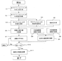
図1乃至図4は、本発明の建設機械の荷重計測装置の実施の形態を示すもので、図1は本発明の荷重計測装置が適用される建設機械の一例であるダンプトラックの側面図、図2は本発明の建設機械の荷重計測装置の一実施の形態を示す構成図、図3は本発明の建設機械の荷重計測装置の一実施の形態の機能構成図、図4は本発明の建設機械の荷重計測装置の一実施の形態の処理フロー図である。
DESCRIPTION OF EMBODIMENTS Hereinafter, embodiments of a load measuring device for construction machine according to the present invention will be described with reference to the drawings.
1 to 4 show an embodiment of a load measuring device for a construction machine according to the present invention. FIG. 1 is a side view of a dump truck which is an example of a construction machine to which the load measuring device of the present invention is applied. FIG. 2 is a block diagram showing an embodiment of a load measuring device for a construction machine according to the present invention, FIG. 3 is a functional block diagram of an embodiment of a load measuring device for a construction machine according to the present invention, and FIG. It is a processing flow figure of one embodiment of a load measuring device of construction machinery.
本発明の荷重計測装置が適用されるダンプトラックは、図1に示すように、車体1と、車体1の前部に設けた運転室2と、車体1に保持され、積荷が積み込まれるボディ3と、このボディ3を一点鎖線で示すように上方向、下方向に回動させるボディ操作シリンダ4と、左右の前輪に配置され、車体1、ボディ3、及びボディ3に積み込まれた積荷を含む重量物を支持する前側の左右のサスペンションシリンダ5aと、左右の後輪に配置され、車体1、ボディ3、及びボディ3に積み込まれた積荷を含む重量物を支持する後側の左右サスペンションシリンダ5bとを備えている。
As shown in FIG. 1, a dump truck to which the load measuring device of the present invention is applied includes a vehicle body 1, a
各サスペンションシリンダ5a,5bには、積荷の荷重を計測する機器として、サスペンションシリンダ5a,5bのシリンダ圧力を計測するための圧カセンサ6a,6bがそれぞれ取り付けられている。車体1の運転室2内には、車体1の前後方向の傾斜角度を検出する傾斜センサ7が設けられている。左右の後輪には、左右の各後輪の回転速度を検出する後輪速度検出器8a,8bが設けられている。車体1には、車体1の速度を検出する車体速度検出器9が設けられている。これらのセンサからの計測信号は、後述する荷重の計算を行う荷重計測の処理装置へ送られる。
次に、荷重計測を行う処理装置の構成、及び機能ブロックを図2及び図3を用いて説明する。
図2は、本発明の建設機械の荷重計測装置の一実施の形態に係る処理装置の構成を示す構成図、図3は、図2に示す本発明の建設機械の荷重計測装置の一実施の形態に係る処理装置の機能構成を示すブロック図であり、これらの図において、図1に示す符号と同符号のものは同一部分であるので、その詳細な説明は省略する。
Next, the configuration and functional blocks of a processing apparatus that performs load measurement will be described with reference to FIGS.
FIG. 2 is a block diagram showing a configuration of a processing apparatus according to an embodiment of a load measuring apparatus for a construction machine of the present invention, and FIG. 3 is an embodiment of the load measuring apparatus for a construction machine of the present invention shown in FIG. It is a block diagram which shows the function structure of the processing apparatus which concerns on a form, In these figures, since the thing of the same code | symbol as the code | symbol shown in FIG. 1 is the same part, the detailed description is abbreviate | omitted.
荷重計測装置の処理装置10には、図2に示すように、前側の左右のサスペンションシリンダ5a、及び後側の左右サスペンションシリンダ5bの各シリンダ圧力を計測するための圧カセンサ6a,6bからの検出信号と、左右の各後輪6の回転速度を検出する後輪速度検出器8a,8bからの検出信号と、車体1の速度を検出する車体速度検出器9からの検出信号とが入力される。
As shown in FIG. 2, the
処理装置10は、図2に示すように、演算を行う演算部11と、演算部11を駆動するタイマ12と、時刻を取得するための時計13と、各種処理(プログラム)を保存する読み込み専用のメモリ(ROM)14と、変数値や荷重計測の結果である荷重データを保存するランダムアクセスメモリ(RAM)15と、センサ入力や通信を行う入力インターフェース16と、演算部11の演算結果を表示装置や外部装置へ出力を行う出力インターフェース17とを有している。また、処理装置10は、出力インターフェース17を介して管理センター又は車体1の運転室内に設置した表示装置20に荷重量を表示することができる。
As illustrated in FIG. 2, the
RAM15には、図3に示す前側の左右のサスペンションシリンダ5a、及び後側の左右サスペンションシリンダ5bの各シリンダの断面積の値Dと、前側の左右のサスペンションシリンダ5a及び後側の左右サスペンションシリンダ5bによって支持されている車体1側の重量Gと、サスペンションシリンダ5a,5bに作用する全荷重Ptを傾斜センサ7からの車体1の傾斜角度θに基づいて傾斜が作用していない場合の全荷重Ptとして求めるための補正全荷重Pt特性Aと、前側のサスペンションシリンダ5aに作用する荷重PFと後側のサスペンションシリンダ5bに作用する荷重PRとのサスペンション荷重比Xt(Xt=PF/PR)を傾斜センサ7からの車体1の傾斜角度θに基づいて傾斜が作用していない場合の荷重比Xとして求めるための補正前後荷重比Xの特性Bと、補正前後荷重比Xに基づいて全荷重Ptの偏心積込補正比率Xaを求めるための全荷重Ptの補正比率の特性Cとを記憶している。
The
次に、処理装置10における演算部11の処理機能の構成を、図3を用いて説明する。演算部11は、大略的にボディ3に積み込まれた積荷量(積載量)を演算する積載荷重演算手段110と、最終積載量を確認する最終積載量確認手段130とを備えている。
Next, the configuration of the processing function of the
積載荷重演算手段110は、前側の左右のサスペンションシリンダ5aの各シリンダ圧力を計測するための圧カセンサ6aからのシリンダ圧と予め記憶したシリンダ5aの断面積の値Dとをそれぞれ掛け算して前側の左右のサスペンションシリンダ5aにそれぞれ作用する荷重を演算する各掛算器111と、後側の左右のサスペンションシリンダ5bの各シリンダ圧力を計測するための圧カセンサ6bからのシリンダ圧と予め記憶したシリンダ5bの断面積の値Dとをそれぞれ掛け算して後側の左右のサスペンションシリンダ5bにそれぞれ作用する荷重を演算する各掛算器112と、各掛算器111からの前側の左右のサスペンションシリンダ5aの荷重を加算して前側のサスペンションシリンダ5aに作用する前側荷重PFを演算する加算器113と、各掛算器112からの後側の左右のサスペンションシリンダ5bに作用する後側荷重PRを演算する加算器114と、加算器113からの前側荷重PFと加算器114からの後側荷重PRとを加算してサスペンションシリンダ5a,5bの全荷重Ptaを演算する加算器115と、加算器115からのサスペンションシリンダ5a,5bの全荷重Ptaを傾斜センサ7からの傾斜角度θと予め記憶した補正全荷重Pt特性Aとに基づいて車体1が傾斜していない場合の補正全荷重Ptを演算する全荷重補正演算部116と、加算器113からの前側荷重PFと加算器114からの後側荷重PRとの前後荷重比Xt(Xt=PF/PR)を演算する除算器117と、除算器117からの前後荷重比Xtを傾斜センサ7からの傾斜角度θと予め記憶した補正前後荷重比Xの特性Bとに基づいて車体1が傾斜していない場合の補正前後荷重比Xを演算する前後荷重比補正演算部118と、前後荷重比補正演算部118からの補正前後荷重比Xと全荷重Ptの偏心積込補正比率の特性Cとに基づいて全荷重Ptの偏心積込補正比率Xaを演算する全荷重補正比率演算部119と、全荷重補正演算部116からの補正全荷重Ptに全荷重補正比率演算部119からの全荷重Ptの偏心積込補正比率Yを除算する除算器120と、除算器120からの全荷重Ptから前側の左右のサスペンションシリンダ5a及び後側の左右サスペンションシリンダ5bによって支持されている車体1側の重量Gを減算して積載荷重Wを演算する減算器121とを備えている。
The load load calculating means 110 multiplies the cylinder pressure from the
前述した最終積載荷重確認手段130は、積載荷重演算手段110からの積載荷重Wを一定の時間内で数回サンプリング計測する積載荷重Wの振れ幅計測部131と、積載荷重Wの振れ幅計測部131からの計測値の平均値を求め、この平均値に対し最大計測値と最小計測値の差が最小になったことを確認する積載荷重の最小振れ幅確認部132と、左右の各後輪の回転速度を検出する後輪速度検出器8a,8bからの各速度の差を演算する速度差検出器133と、車体速度検出器9からの車体1の速度が予め設定した設定値(例えば、数km/h)以上に達した場合、所謂、荷重計測可能な走行状態の場合(条件1)と,積載荷重の最小振れ幅確認部132からの積載荷重が最小振れ幅内である場合(条件2)と,速度差検出器133からの後輪速度検出器8a,8bからの各速度の差が予め設定した設定値より小さい場合、所謂、曲線状の経路ではなく直線状の経路を走行していると判断できる場合(条件3)とが満たされた場合に、減算器121からの積載荷重Wを最終の積載荷重として出力し、条件が満たされない場合には、減算器121からの積載荷重Wを最終の積載荷重の出力として無効とする最終確認演算部(論理積演算部)134とを備えている。The final load
次に、上述した本発明の建設機械の荷重計測装置の一実施の形態の処理動作を、図2乃至図4を用いて説明する。
なお、図4は、本発明の建設機械の荷重計測装置の一実施の形態の処理フローを示す図である。
Next, the processing operation of the embodiment of the load measuring apparatus for construction machine according to the present invention described above will be described with reference to FIGS.
FIG. 4 is a diagram showing a processing flow of an embodiment of the load measuring device for a construction machine according to the present invention.
図3に示す処理装置10における演算部11の積載荷重演算手段110における各掛算器111は、積載荷重演算手段110に取り込まれた圧カセンサ6aからの前側の左右のサスペンションシリンダ5aの各シリンダ圧力(図4の手順S1)と予め記憶したシリンダ5aの断面積の値Dとをそれぞれ掛け算して、前側の左右のサスペンションシリンダ5aにそれぞれ作用する荷重を演算する(図4の手順S2)。
Each
また、各掛算器112は、積載荷重演算手段110に取り込まれた後側の左右のサスペンションシリンダ5bの各シリンダ圧力を計測するための圧カセンサ6bからのシリンダ圧(図4の手順S1)と予め記憶したシリンダ5bの断面積の値Dとをそれぞれ掛け算して後側の左右のサスペンションシリンダ5bにそれぞれ作用する荷重を演算する(図4の手順S2)。
Each
加算器113は、各掛算器111からの前側の左右のサスペンションシリンダ5aの荷重を加算して前側のサスペンションシリンダ5aに作用する前側荷重PFを演算する。また、加算器114は、各掛算器112からの後側の左右のサスペンションシリンダ5bに作用する後側荷重PRを演算する。加算器115は、加算器113からの前側荷重PFと加算器114からの後側荷重PRとを加算してサスペンションシリンダ5a,5bの全荷重Ptaを演算する(図4の手順S3)。
The
除算器117は、加算器113からの前側荷重PFと加算器114からの後側荷重PRとの前後荷重比Xt(Xt=PF/PR)を演算する(図4の手順S4)。
全荷重補正演算部116は、加算器115からのサスペンションシリンダ5a,5bの全荷重Ptaを傾斜センサ7からの傾斜角度θ(図4の手順S5)と予め記憶した補正全荷重Pt特性Aとに基づいて車体1が傾斜していない場合の補正全荷重Ptを演算する(図4の手順S6)。
The total load
前後荷重比補正演算部118は、除算器117からの前後荷重比Xtを傾斜センサ7からの傾斜角度θ(図4の手順S5)と予め記憶した補正前後荷重比Xの特性Bとに基づいて車体1が傾斜していない場合の補正前後荷重比Xを演算する(図4の手順S6)。
Load ratio
全荷重補正比率演算部119は、前後荷重比補正演算部118からの補正前後荷重比Xと全荷重Ptの偏心積込補正比率の特性Cとに基づいて全荷重Ptの偏心積込補正比率Xaを演算する(図4の手順S6)。
Total load correction
除算器120は、全荷重補正演算部116からの補正全荷重Ptに全荷重補正比率演算部119からの全荷重Ptの偏心積込補正比率Yを除算する(図4の手順S6)。減算器121は、除算器120からの全荷重Ptから前側の左右のサスペンションシリンダ5a及び後側の左右サスペンションシリンダ5bによって支持されている車体1側の重量Gを減算して積載荷重Wを演算する(図4の手順S6)。
Divider 1 20 divides the eccentric loading correction ratio Y of the total load Pt from full load correction
次に、最終積載荷重確認手段130における積載荷重Wの振れ幅計測部131は、積載荷重演算手段110からの積載荷重Wを一定の時間内で数回サンプリング計測する。積載荷重の最小振れ幅確認部132は、積載荷重Wの振れ幅計測部131からの計測値の平均値を求め、この平均値に対し最大計測値と最小計測値の差が最小になったことを確認する(図4の手順S7)。また、速度差検出器133は、左右の各後輪の回転速度を検出する後輪速度検出器8a,8bからの各速度(図4の手順S8)の差を演算する(図4の手順S9)。Next, the run-out width measuring unit 131 of the loaded load W in the final loaded
最終確認演算部134は、車体速度検出器9からの車体1の速度が予め設定した設定値(例えば、数km/h)以上に達した場合、所謂、荷重計測可能な走行状態の場合(条件1)と,積載荷重の最小振れ幅確認部132からの積載荷重が最小振れ幅内である場合(条件2)と,速度差検出器133からの後輪速度検出器8a,8bからの各速度の差が予め設定した設定値より小さい場合、所謂、曲線状の経路ではなく直線状の経路を走行していると判断できる場合(条件3)とが満たされた場合(図4の手順S10)に、減算器121からの積載荷重Wを最終の積載量として出力する(図4の手順S11)。また、最終確認演算部134は、条件1乃至3が満たされない場合には、減算器121からの積載荷重Wを最終の積載荷重の出力として無効とする。
上述した本発明の実施の形態によれば、建設機械が曲線状の経路を走行している際には、その際に計測した積載荷重の出力を無効にするので、建設機械の走行中における積載荷重の計測の精度が向上する。その結果、建設機械の生産性の管理が向上する。When the speed of the vehicle body 1 from the vehicle body speed detector 9 reaches a preset value (for example, several km / h) or more, the final
According to the above-described embodiment of the present invention, when the construction machine is traveling along a curved path, the output of the loaded load measured at that time is invalidated. The accuracy of load measurement is improved. As a result, the productivity management of the construction machine is improved.
なお、上述の実施の形態においては、最終確認演算部134は、車体速度検出器9からの車体1の速度が予め設定した設定値(例えば、数km/h)以上に達した場合、所謂、荷重計測可能な走行状態の場合(条件1)と、積載荷重の最小振れ幅確認部132からの積載荷重が最小振れ幅内である場合(条件2)と、速度差検出器133からの後輪速度検出器8a,8bからの各速度の差が予め設定した設定値より小さい場合、所謂、曲線状の経路ではなく直線状の経路を走行していると判断できる場合(条件3)との条件が満たされた場合に、減算器121からの積載荷重Wを最終の積載荷重として出力するようにしたが、前述した条件3が満たされた場合に、最終確認演算部134は、減算器121からの積載荷重Wを最終の積載量として出力することも可能である。
In the above-described embodiment, the final
また、最終確認演算部134において、車体速度検出器9からの車体1の速度が予め設定した設定値(例えば、数km/h)以上に達した場合、所謂、荷重計測可能な走行状態の場合(条件1)として設定したが、車体速度を数回取込み、その平均値処理後、数秒間の速度変化が設定値以内であれば、条件1が満たされたとして扱うことも可能である。
Further, in the final
また、最終確認演算部134において、速度差検出器133からの後輪速度検出器8a,8bからの各速度の差が予め設定した設定値以上の場合、条件3を満たしていないとして、無効にしたが、無効後、後輪速度検出器8a,8bからの各速度の差が設定値よりも小さい値で、数秒後に前述した条件1,2が満たされていれば、減算器121からの積載荷重Wを最終の積載荷重として出力することも可能である。
Further, in the final
なお、上述の実施の形態においては、建設機械であるダンプトラッックが曲線状の経路を走行している状態を、後輪速度検出器8a,8bからの各速度の差から求めるようにしたが、建設機械の左右の前輪の操舵角度をそれぞれ検出する操舵角度検出器で求めることも可能である。
In the above-described embodiment, the state where the dump truck, which is a construction machine, is traveling on a curved path is determined from the difference between the speeds from the rear
この場合、最終積載荷重確認手段130における最終確認演算部134は、前記操舵角度検出器からの操舵角度が予め設定した設定値(例えば、直線状の経路走行時における操舵角)と同じ場合、前記処理装置で演算した積載荷重Wを最終の積載荷重として出力し、予め設定した設定値以上に達した場合には、前記処理装置で演算した積載荷重Wを最終の積載荷重の出力として無効とする手順を実行する。
In this case, when the steering angle from the steering angle detector is the same as a preset value (for example, a steering angle during linear route travel) , the final
1 車体
2 運転室
3 ボディ
4 ボディ操作シリンダ4
5a 前側のサスペンションシリンダ
5b 後側のサスペンションシリンダ
6a 圧カセンサ
6b 圧カセンサ
8a 後輪速度検出器
8b 後輪速度検出器
9 車体速度検出器
10 荷重計測装置の処理装置
11 演算部
14 読み込み専用のメモリ(ROM)
15 ランダムアクセスメモリ(RAM)
110 積載荷重演算手段
130 最終積載量確認手段
134 最終確認演算部
1
5a Front suspension cylinder 5b
15 Random access memory (RAM)
110 Load load calculating means 130 Final load amount checking means 134 Final check calculating section
Claims (4)
前記建設機械の左右の後輪の速度をそれぞれ検出する後輪速度検出器と、
前記各後輪速度検出器からの速度差を検出する速度差検出器と、
車体の速度を検出する車体速度検出器と、
前記処理装置からの積載荷重Wを一定の時間内で数回サンプリング計測する積載荷重Wの振れ幅計測部と、
前記積載荷重Wの振れ幅計測部からの計測値の平均値を求め、この平均値に対し最大計測値と最小計測値の差が最小になったことを確認する積載荷重の最小振れ幅確認部と、
前記車体速度検出器からの車体の速度が予め設定した設定値以上に達した場合(条件1)と,前記積載荷重の最小振れ幅確認部からの積載荷重が最小振れ幅内である場合(条件2)と,前記速度差検出器からの左右の後輪の速度の差が予め設定した設定値より小さい場合(条件3)とが満たされた場合に、前記処理装置で演算した積載荷重Wを最終の積載荷重として出力し、前記条件のいずれか1つが満たされていない場合に、前記処理装置で演算した積載荷重Wを最終の積載荷重の出力として無効とする最終確認演算部を有する最終積載荷重確認手段とを備えた
ことを特徴とする建設機械の荷重計測装置。 In a load measuring device for a construction machine having a processing device for calculating the load loaded on the body of the construction machine by taking the cylinder pressure of the front suspension cylinder and the rear suspension cylinder by a pressure sensor,
A rear wheel speed detector for respectively detecting the speed of the left and right rear wheels of the construction machine;
A speed difference detector for detecting a speed difference from each of the rear wheel speed detectors;
A vehicle speed detector for detecting the speed of the vehicle body,
A runout width measurement unit of the load W that samples and measures the load W from the processing device several times within a predetermined time;
An average value of the measurement values from the runout measurement unit of the load load W is obtained, and a minimum runout width check unit of the load load is confirmed to confirm that the difference between the maximum measurement value and the minimum measurement value is minimized with respect to the average value. When,
When the vehicle body speed from the vehicle body speed detector reaches a preset value or more (Condition 1), and when the loading load from the minimum deflection checking unit of the loading load is within the minimum deflection width (Condition 1) 2) and the case where the difference between the speeds of the left and right rear wheels from the speed difference detector is smaller than a preset value (condition 3), the loaded load W calculated by the processing device is The final loading load is output as a final loading load, and has a final confirmation calculation unit that invalidates the loading load W calculated by the processing device as an output of the final loading load when any one of the conditions is not satisfied. A load measuring device for a construction machine, comprising a load confirmation means.
前記最終積載荷重確認手段における前記最終確認演算部は、前記車体速度検出器からの車体の速度を数回取込み、その平均値処理後、数秒間の速度変化が設定値以内であれば、条件1が満たされたとして扱う手段を更に備えた
ことを特徴とする建設機械の荷重計測装置。 In the load measuring device of the construction machine according to claim 1 ,
The final confirmation calculation unit in the final load load confirmation means takes in the vehicle body speed from the vehicle body speed detector several times, and after processing the average value, if the speed change for several seconds is within a set value, Condition 1 load measuring device for a construction machine wherein, further comprising a hand-stage treated as is met.
前記最終積載荷重確認手段における前記最終確認演算部は、前記速度差検出器からの後輪速度検出器からの各速度の差が前記設定値よりも小さい値で、数秒後に前述した条件1,2が満たされていれば、前記処理装置からの積載荷重Wを最終の積載荷重として出力する手段を更に備えた
ことを特徴とする建設機械の荷重計測装置。 In the load measuring device of the construction machine according to claim 1 ,
The final check calculation unit in the final load load checking means is configured such that the difference between the speeds from the speed difference detector from the rear wheel speed detector is smaller than the set value, and the conditions 1 and 2 described above after a few seconds. if so satisfied, the load measuring system for a construction machine, characterized by further comprising a means to output the loading weight W from the processing unit as a final loading weight of.
前記建設機械は、ボディに積載した積載荷を移送するダンプトラックである
ことを特徴とする建設機械の荷重計測装置。 In the load measuring device of the construction machine according to any one of claims 1 to 3 ,
The construction machine is a dump truck for transferring a load loaded on a body.
Priority Applications (5)
| Application Number | Priority Date | Filing Date | Title |
|---|---|---|---|
| JP2009033094A JP5160468B2 (en) | 2009-02-16 | 2009-02-16 | Construction machine load measuring device |
| US12/699,233 US8437982B2 (en) | 2009-02-16 | 2010-02-03 | Apparatus for measuring load of construction machine |
| AU2010200508A AU2010200508B2 (en) | 2009-02-16 | 2010-02-11 | Apparatus for measuring load of construction machine |
| CN201010115293.XA CN101806610B (en) | 2009-02-16 | 2010-02-11 | Apparatus for measuring load of construction machine |
| US13/666,491 US20130185019A1 (en) | 2009-02-16 | 2012-11-01 | Apparatus for measuring load of construction machine |
Applications Claiming Priority (1)
| Application Number | Priority Date | Filing Date | Title |
|---|---|---|---|
| JP2009033094A JP5160468B2 (en) | 2009-02-16 | 2009-02-16 | Construction machine load measuring device |
Publications (3)
| Publication Number | Publication Date |
|---|---|
| JP2010190617A JP2010190617A (en) | 2010-09-02 |
| JP2010190617A5 JP2010190617A5 (en) | 2012-08-23 |
| JP5160468B2 true JP5160468B2 (en) | 2013-03-13 |
Family
ID=42560684
Family Applications (1)
| Application Number | Title | Priority Date | Filing Date |
|---|---|---|---|
| JP2009033094A Active JP5160468B2 (en) | 2009-02-16 | 2009-02-16 | Construction machine load measuring device |
Country Status (4)
| Country | Link |
|---|---|
| US (2) | US8437982B2 (en) |
| JP (1) | JP5160468B2 (en) |
| CN (1) | CN101806610B (en) |
| AU (1) | AU2010200508B2 (en) |
Cited By (3)
| Publication number | Priority date | Publication date | Assignee | Title |
|---|---|---|---|---|
| WO2015025362A1 (en) * | 2013-08-20 | 2015-02-26 | 日立建機株式会社 | Dump truck |
| WO2016181697A1 (en) * | 2015-05-13 | 2016-11-17 | 日立建機株式会社 | Work-machine load measuring device |
| US10317273B2 (en) | 2015-05-26 | 2019-06-11 | Hitachi Construction Machinery Co., Ltd. | Load measuring apparatus for construction machine |
Families Citing this family (13)
| Publication number | Priority date | Publication date | Assignee | Title |
|---|---|---|---|---|
| JP5160468B2 (en) * | 2009-02-16 | 2013-03-13 | 日立建機株式会社 | Construction machine load measuring device |
| US8755977B2 (en) * | 2012-09-21 | 2014-06-17 | Siemens Industry, Inc. | Method and system for preemptive load weight for mining excavating equipment |
| DE102013201630A1 (en) * | 2013-01-31 | 2014-07-31 | Siemens Aktiengesellschaft | Brake unit for a vehicle and vehicle with such a brake unit |
| DE102013103312A1 (en) | 2013-04-03 | 2014-10-09 | Schmitz Cargobull Gotha GmbH | Weighing system and method for weighing a load of a dump truck |
| US9109942B2 (en) | 2013-04-15 | 2015-08-18 | Caterpillar Inc. | Method of calculating payload material weight and machine using same |
| JP5997720B2 (en) * | 2014-03-31 | 2016-09-28 | 日立建機株式会社 | Construction machine load measuring device |
| GB201503872D0 (en) * | 2015-03-06 | 2015-04-22 | Hyva Holding Bv | Method and system for operating a tipper |
| JP2018077810A (en) * | 2016-11-11 | 2018-05-17 | 富士通株式会社 | Loading determination program, loading determination method and loading determination device |
| JP6737202B2 (en) * | 2017-02-16 | 2020-08-05 | 株式会社島津製作所 | forklift |
| US10752075B1 (en) * | 2017-04-28 | 2020-08-25 | Oshkosh Defense, Llc | Systems and methods for determining vehicle characteristics |
| CN110646072A (en) * | 2019-09-29 | 2020-01-03 | 武汉依迅电子信息技术有限公司 | Construction vehicle load measuring method and device |
| KR102340301B1 (en) * | 2020-01-28 | 2021-12-15 | 전형율 | Automatic locking of containers |
| CN112757996B (en) * | 2021-02-26 | 2022-09-09 | 苏州市正和汽车贸易有限公司 | PTA transport vechicle that screw conveyer was unloaded |
Family Cites Families (20)
| Publication number | Priority date | Publication date | Assignee | Title |
|---|---|---|---|---|
| US5182712A (en) * | 1990-09-14 | 1993-01-26 | Caterpillar Inc. | Dynamic payload monitor |
| US5376760A (en) * | 1993-04-26 | 1994-12-27 | Horsley; Charles L. | Truck load indicator apparatus |
| JP3524605B2 (en) * | 1994-12-13 | 2004-05-10 | 西松建設株式会社 | Unmanned unloading vehicle and unmanned unloading measurement method |
| JP3441564B2 (en) * | 1995-07-07 | 2003-09-02 | 本田技研工業株式会社 | Control method of rear wheel steering device |
| US6044313A (en) * | 1997-11-26 | 2000-03-28 | Caterpillar Inc. | Method and apparatus for monitoring ton-miles-per-hour for tires on a mobile machine |
| DE19837380A1 (en) * | 1998-08-18 | 2000-02-24 | Zahnradfabrik Friedrichshafen | Method to determine mass of vehicle; involves obtaining measurements to determine traction force variable and movement variable |
| JP2000198402A (en) * | 1999-01-05 | 2000-07-18 | Sumitomo Electric Ind Ltd | Object detector |
| JP2002037405A (en) * | 2000-07-26 | 2002-02-06 | Sumitomo Metal Ind Ltd | Refuse generation information collecting system and garbage truck |
| FR2814238B1 (en) * | 2000-09-15 | 2004-06-25 | Dufournier Technologies S A S | METHOD AND SYSTEM OR CENTRAL FOR MONITORING THE CONDITION OF TIRES, AND DETECTION OF THE PRESENCE OF CHAINS OR SNOW NAILS, ON A VEHICLE |
| DE10243516A1 (en) * | 2002-09-19 | 2004-04-01 | Robert Bosch Gmbh | Device for determining a total mass of a vehicle |
| JP4433688B2 (en) * | 2003-02-12 | 2010-03-17 | 日本精工株式会社 | Load measuring device for rolling bearing unit and rolling bearing unit for load measurement |
| JP2005008094A (en) * | 2003-06-20 | 2005-01-13 | Honda Motor Co Ltd | Threshold setting method of tire air pressure lowering detector |
| JP2005043267A (en) * | 2003-07-24 | 2005-02-17 | Hitachi Constr Mach Co Ltd | Load-measuring device of construction equipment |
| JP2005084003A (en) * | 2003-09-11 | 2005-03-31 | Honda Motor Co Ltd | Tire pressure detecting apparatus |
| US7247803B2 (en) * | 2004-01-15 | 2007-07-24 | Komatsu Ltd. | Loaded weight measurement method and loaded weight measurement device for dump truck |
| JP4161923B2 (en) * | 2004-03-09 | 2008-10-08 | 株式会社デンソー | Vehicle stabilization control system |
| US20090102277A1 (en) * | 2005-08-24 | 2009-04-23 | Toshiki Ezoe | Automatic Brake Control Device |
| JP2007210592A (en) * | 2005-10-28 | 2007-08-23 | Hino Motors Ltd | Automatic braking control device |
| US20100198491A1 (en) * | 2009-02-05 | 2010-08-05 | Paccar Inc | Autonomic vehicle safety system |
| JP5160468B2 (en) * | 2009-02-16 | 2013-03-13 | 日立建機株式会社 | Construction machine load measuring device |
-
2009
- 2009-02-16 JP JP2009033094A patent/JP5160468B2/en active Active
-
2010
- 2010-02-03 US US12/699,233 patent/US8437982B2/en active Active - Reinstated
- 2010-02-11 CN CN201010115293.XA patent/CN101806610B/en active Active
- 2010-02-11 AU AU2010200508A patent/AU2010200508B2/en active Active
-
2012
- 2012-11-01 US US13/666,491 patent/US20130185019A1/en not_active Abandoned
Cited By (6)
| Publication number | Priority date | Publication date | Assignee | Title |
|---|---|---|---|---|
| WO2015025362A1 (en) * | 2013-08-20 | 2015-02-26 | 日立建機株式会社 | Dump truck |
| JP6027248B2 (en) * | 2013-08-20 | 2016-11-16 | 日立建機株式会社 | Dump truck |
| WO2016181697A1 (en) * | 2015-05-13 | 2016-11-17 | 日立建機株式会社 | Work-machine load measuring device |
| JP2016212055A (en) * | 2015-05-13 | 2016-12-15 | 日立建機株式会社 | Work machine load measurement device |
| US10337909B2 (en) | 2015-05-13 | 2019-07-02 | Hitachi Construction Machinery Co., Ltd. | Load measuring apparatus for a working machine |
| US10317273B2 (en) | 2015-05-26 | 2019-06-11 | Hitachi Construction Machinery Co., Ltd. | Load measuring apparatus for construction machine |
Also Published As
| Publication number | Publication date |
|---|---|
| CN101806610A (en) | 2010-08-18 |
| AU2010200508A1 (en) | 2010-09-02 |
| US8437982B2 (en) | 2013-05-07 |
| JP2010190617A (en) | 2010-09-02 |
| US20100211356A1 (en) | 2010-08-19 |
| CN101806610B (en) | 2014-01-08 |
| AU2010200508B2 (en) | 2011-07-21 |
| US20130185019A1 (en) | 2013-07-18 |
Similar Documents
| Publication | Publication Date | Title |
|---|---|---|
| JP5160468B2 (en) | Construction machine load measuring device | |
| KR102479557B1 (en) | Load weighing method and system for wheel loader | |
| US8155798B2 (en) | Method and device for determining the roll angle of a motorcycle | |
| JP5457201B2 (en) | Use of suspension information in detecting tire pressure deviations in vehicle tires | |
| WO2016189654A1 (en) | Load measuring device for construction machine | |
| JP2010190617A5 (en) | ||
| US8700274B1 (en) | Method of determining when a bed of a hauling machine is empty | |
| US8903612B2 (en) | Method of determining when a payload loading event is occurring in a hauling machine | |
| US10337909B2 (en) | Load measuring apparatus for a working machine | |
| WO2014156903A1 (en) | Delivery vehicle | |
| JP2006273108A (en) | Vehicle state detector | |
| WO2014176063A1 (en) | Method of estimating mass of a payload in a hauling machine | |
| JP5680940B2 (en) | Device for measuring the center of gravity of a vehicle to be weighed on a truck scale | |
| US8019516B2 (en) | Method for measuring the useful load of a telehandler | |
| JP5997720B2 (en) | Construction machine load measuring device | |
| JP3852840B2 (en) | Vehicle load weight measuring device | |
| JP2022184106A (en) | Vehicle body speed estimation device |
Legal Events
| Date | Code | Title | Description |
|---|---|---|---|
| A521 | Written amendment |
Free format text: JAPANESE INTERMEDIATE CODE: A523 Effective date: 20100115 |
|
| A621 | Written request for application examination |
Free format text: JAPANESE INTERMEDIATE CODE: A621 Effective date: 20110624 |
|
| A521 | Written amendment |
Free format text: JAPANESE INTERMEDIATE CODE: A523 Effective date: 20120628 |
|
| A521 | Written amendment |
Free format text: JAPANESE INTERMEDIATE CODE: A523 Effective date: 20120628 |
|
| A977 | Report on retrieval |
Free format text: JAPANESE INTERMEDIATE CODE: A971007 Effective date: 20120918 |
|
| A131 | Notification of reasons for refusal |
Free format text: JAPANESE INTERMEDIATE CODE: A131 Effective date: 20120925 |
|
| A521 | Written amendment |
Free format text: JAPANESE INTERMEDIATE CODE: A523 Effective date: 20121107 |
|
| TRDD | Decision of grant or rejection written | ||
| A01 | Written decision to grant a patent or to grant a registration (utility model) |
Free format text: JAPANESE INTERMEDIATE CODE: A01 Effective date: 20121211 |
|
| A61 | First payment of annual fees (during grant procedure) |
Free format text: JAPANESE INTERMEDIATE CODE: A61 Effective date: 20121212 |
|
| R150 | Certificate of patent or registration of utility model |
Ref document number: 5160468 Country of ref document: JP Free format text: JAPANESE INTERMEDIATE CODE: R150 Free format text: JAPANESE INTERMEDIATE CODE: R150 |
|
| FPAY | Renewal fee payment (event date is renewal date of database) |
Free format text: PAYMENT UNTIL: 20151221 Year of fee payment: 3 |