EP3306191A1 - Combustor - Google Patents
Combustor Download PDFInfo
- Publication number
- EP3306191A1 EP3306191A1 EP15895045.1A EP15895045A EP3306191A1 EP 3306191 A1 EP3306191 A1 EP 3306191A1 EP 15895045 A EP15895045 A EP 15895045A EP 3306191 A1 EP3306191 A1 EP 3306191A1
- Authority
- EP
- European Patent Office
- Prior art keywords
- combustion
- clinker
- air
- combustion chamber
- grate
- Prior art date
- Legal status (The legal status is an assumption and is not a legal conclusion. Google has not performed a legal analysis and makes no representation as to the accuracy of the status listed.)
- Withdrawn
Links
- 238000002485 combustion reaction Methods 0.000 claims abstract description 323
- 239000000446 fuel Substances 0.000 claims abstract description 51
- XLYOFNOQVPJJNP-UHFFFAOYSA-N water Substances O XLYOFNOQVPJJNP-UHFFFAOYSA-N 0.000 claims description 9
- 238000005192 partition Methods 0.000 claims description 7
- 230000000903 blocking effect Effects 0.000 claims description 6
- 230000003247 decreasing effect Effects 0.000 claims description 4
- 239000000470 constituent Substances 0.000 description 4
- 239000004449 solid propellant Substances 0.000 description 3
- 230000000694 effects Effects 0.000 description 2
- 239000007789 gas Substances 0.000 description 2
- 239000000463 material Substances 0.000 description 2
- 238000000034 method Methods 0.000 description 2
- 239000000567 combustion gas Substances 0.000 description 1
- 238000001816 cooling Methods 0.000 description 1
- 238000007599 discharging Methods 0.000 description 1
- 239000010791 domestic waste Substances 0.000 description 1
- 238000012986 modification Methods 0.000 description 1
- 230000004048 modification Effects 0.000 description 1
- 238000004064 recycling Methods 0.000 description 1
- 230000000630 rising effect Effects 0.000 description 1
Images



Classifications
-
- F—MECHANICAL ENGINEERING; LIGHTING; HEATING; WEAPONS; BLASTING
- F23—COMBUSTION APPARATUS; COMBUSTION PROCESSES
- F23B—METHODS OR APPARATUS FOR COMBUSTION USING ONLY SOLID FUEL
- F23B40/00—Combustion apparatus with driven means for feeding fuel into the combustion chamber
- F23B40/04—Combustion apparatus with driven means for feeding fuel into the combustion chamber the fuel being fed from below through an opening in the fuel-supporting surface
-
- F—MECHANICAL ENGINEERING; LIGHTING; HEATING; WEAPONS; BLASTING
- F23—COMBUSTION APPARATUS; COMBUSTION PROCESSES
- F23B—METHODS OR APPARATUS FOR COMBUSTION USING ONLY SOLID FUEL
- F23B1/00—Combustion apparatus using only lump fuel
- F23B1/30—Combustion apparatus using only lump fuel characterised by the form of combustion chamber
-
- F—MECHANICAL ENGINEERING; LIGHTING; HEATING; WEAPONS; BLASTING
- F23—COMBUSTION APPARATUS; COMBUSTION PROCESSES
- F23B—METHODS OR APPARATUS FOR COMBUSTION USING ONLY SOLID FUEL
- F23B1/00—Combustion apparatus using only lump fuel
- F23B1/30—Combustion apparatus using only lump fuel characterised by the form of combustion chamber
- F23B1/32—Combustion apparatus using only lump fuel characterised by the form of combustion chamber rotating
-
- F—MECHANICAL ENGINEERING; LIGHTING; HEATING; WEAPONS; BLASTING
- F23—COMBUSTION APPARATUS; COMBUSTION PROCESSES
- F23B—METHODS OR APPARATUS FOR COMBUSTION USING ONLY SOLID FUEL
- F23B30/00—Combustion apparatus with driven means for agitating the burning fuel; Combustion apparatus with driven means for advancing the burning fuel through the combustion chamber
-
- F—MECHANICAL ENGINEERING; LIGHTING; HEATING; WEAPONS; BLASTING
- F23—COMBUSTION APPARATUS; COMBUSTION PROCESSES
- F23B—METHODS OR APPARATUS FOR COMBUSTION USING ONLY SOLID FUEL
- F23B7/00—Combustion techniques; Other solid-fuel combustion apparatus
- F23B7/002—Combustion techniques; Other solid-fuel combustion apparatus characterised by gas flow arrangements
-
- F—MECHANICAL ENGINEERING; LIGHTING; HEATING; WEAPONS; BLASTING
- F23—COMBUSTION APPARATUS; COMBUSTION PROCESSES
- F23B—METHODS OR APPARATUS FOR COMBUSTION USING ONLY SOLID FUEL
- F23B80/00—Combustion apparatus characterised by means creating a distinct flow path for flue gases or for non-combusted gases given off by the fuel
- F23B80/02—Combustion apparatus characterised by means creating a distinct flow path for flue gases or for non-combusted gases given off by the fuel by means for returning flue gases to the combustion chamber or to the combustion zone
-
- F—MECHANICAL ENGINEERING; LIGHTING; HEATING; WEAPONS; BLASTING
- F23—COMBUSTION APPARATUS; COMBUSTION PROCESSES
- F23G—CREMATION FURNACES; CONSUMING WASTE PRODUCTS BY COMBUSTION
- F23G5/00—Incineration of waste; Incinerator constructions; Details, accessories or control therefor
- F23G5/24—Incineration of waste; Incinerator constructions; Details, accessories or control therefor having a vertical, substantially cylindrical, combustion chamber
-
- F—MECHANICAL ENGINEERING; LIGHTING; HEATING; WEAPONS; BLASTING
- F23—COMBUSTION APPARATUS; COMBUSTION PROCESSES
- F23J—REMOVAL OR TREATMENT OF COMBUSTION PRODUCTS OR COMBUSTION RESIDUES; FLUES
- F23J1/00—Removing ash, clinker, or slag from combustion chambers
- F23J1/02—Apparatus for removing ash, clinker, or slag from ash-pits, e.g. by employing trucks or conveyors, by employing suction devices
-
- F—MECHANICAL ENGINEERING; LIGHTING; HEATING; WEAPONS; BLASTING
- F23—COMBUSTION APPARATUS; COMBUSTION PROCESSES
- F23L—SUPPLYING AIR OR NON-COMBUSTIBLE LIQUIDS OR GASES TO COMBUSTION APPARATUS IN GENERAL ; VALVES OR DAMPERS SPECIALLY ADAPTED FOR CONTROLLING AIR SUPPLY OR DRAUGHT IN COMBUSTION APPARATUS; INDUCING DRAUGHT IN COMBUSTION APPARATUS; TOPS FOR CHIMNEYS OR VENTILATING SHAFTS; TERMINALS FOR FLUES
- F23L9/00—Passages or apertures for delivering secondary air for completing combustion of fuel
- F23L9/06—Passages or apertures for delivering secondary air for completing combustion of fuel by discharging the air into the fire bed
Definitions
- the present disclosure relates to a combustor, and more particularly, to a combustor recovering combustion heat generated by burning solid fuel in a combustion chamber to use recovered heat as energy.
- combustors generating heat energy by igniting and burning fuel in combustion chambers are utilized to obtain thermal energy.
- fuel used in such combustors solid fuel, obtained from domestic waste, and the like, has widely been used in view of economy and recycling resources.
- An aspect of the present disclosure is to provide a combustor, in which removal efficiency of clinker may be increased by smoothly discharging combustion air from a combustion space to a clinker collection portion.
- a combustor includes a combustion chamber including a grate therein and a combustion space formed above the grate; a fuel supply portion downwardly connected to a central portion of the grate to supply fuel to an upper portion of the grate; an air supply part connected to a side portion of the combustion chamber to be inclined with respect to a horizontal plane, to supply combustion air such that the combustion air rotates in the combustion space; a clinker collection portion downwardly communicating with a gap formed between an inner wall of the combustion chamber and the grate, to collect clinker generated by combustion of fuel performed in the combustion space, in the clinker collection portion through the gap; and a reintroduction channel passing through the grate from the clinker collection portion to the combustion space, such that the combustion air, having flowed from the combustion space to the clinker collection portion through the gap, is reintroduced into the combustion space.
- the reintroduction channel may be provided as a plurality of reintroduction channels, and may have a cross-sectional area decreasing toward a central portion of the combustion chamber in a lower portion of the combustion chamber.
- the reintroduction channel may be provided as a plurality of reintroduction channels, and the number of the plurality of reintroduction channels may be reduced toward a central portion of the combustion chamber in a lower portion of the combustion chamber.
- the combustor may further include a flow controlling member controlling a flow structure of the combustion air in the clinker collection portion, to restrict the clinker in the clinker collection portion from being reintroduced into the combustion space together with the combustion air.
- the flow controlling member may be configured to extend downwardly from a lower portion of the combustion chamber to an inside of the clinker collection portion.
- the flow controlling member may extend downwardly, toward a center of the combustion chamber.
- the combustor may further include a partition wall configured to be able to separate an air supply passage and a clinker collection passage from each other in the gap, in such a manner that the clinker is collected in the clinker collection portion through the gap when the combustion air provided by the air supply part is supplied into the combustion chamber through the gap.
- the combustor may further include a check member provided inside the clinker collection portion and configured to have a through hole having a downwardly-narrowed shape to block upwardly reverse passage of the clinker having passed downwardly.
- the clinker collection portion may accommodate water in a lower portion thereof, such that the clinker is deposited in the water.
- the air supply part may be configured to be connected to an outer wall of the combustion chamber, spaced apart from the inner wall while surrounding the inner wall, in such a manner that the combustion air rotates along an external surface of the inner wall of the combustion chamber, and then, is introduced into the combustion space through an inlet.
- the air supply part may include an upper air supply portion connected to an upper side portion of the combustion chamber to supply the combustion air in such a manner that the combustion air rotates downwardly in the combustion space; and a lower air supply portion connected to a lower side portion of the combustion chamber to supply combustion air in such a manner that the combustion air is in contact with the fuel on an upper portion of the grate to be burned and then rises along a central portion of the combustion chamber.
- the combustor may further include a guide member having a downwardly-opening structure and disposed to protrude from an inlet, through which the combustion air is introduced into the combustion space, inwardly of the combustion space, to guide the combustion air in such a manner that the combustion air rotates downwardly in the combustion space along the inner wall of the combustion chamber.
- the grate may be rotationally driven, based on the fuel supply portion.
- the fuel supply portion may pass through the grate to protrude into the combustion space, and may be configured to have a screw form to continuously supply the fuel.
- the fuel supply portion may pass through the grate to protrude into the combustion space, and may be provided with a blocking member, having a downwardly enlarged diameter and mounted on an end portion of the fuel supply portion, adjacent to the combustion space, to distribute the fuel laterally while blocking an upward movement of the fuel.
- the combustion chamber may have a frustoconical shape, in which an upper portion is relatively narrow and a lower portion is relatively wide.
- a reintroduction channel may be configured to pass through a grate from a clinker collection portion to a combustion space, such that combustion air discharged from the combustion space to the clinker collection portion through a gap may be reintroduced into the combustion space.
- combustion air may be smoothly discharged to the clinker collection portion from the combustion space, the efficiency of removing clinker from a combustion space may be increased.
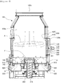
- FIG. 1 is a view illustrating an interior of a combustor according to an exemplary embodiment
- FIG. 2 is a view illustrating an interior of a combustor according to another exemplary embodiment.
- a combustor may include a combustion chamber 100 in which a fuel F, for example, a solid-type fuel, is burned, a fuel supply portion 200 supplying the fuel F to the combustion chamber 100, and an air supply part supplying combustion air A to the combustion chamber 100, and as main constituent characteristics, may include a clinker collection portion 520 in which clinker generated by combustion of the fuel F in the combustion space 100a is collected, and a reintroduction channel 530 passing through a grate 130 from the clinker collection portion 520 to the combustion space 100a.
- the clinker may include ash as a remaining material after the fuel is burned.
- the combustion space 100a may be formed in the combustion chamber 100
- the grate 130 may be installed in a lower portion of the combustion space 100a
- an outlet 100c may be formed in an upper portion thereof.
- the grate 130 may be configured to have the fuel F seated thereon and configured to be provided with the fuel supply portion 200 downwardly connected to a central portion of the grate.
- the combustion chamber 100 may have a frustoconical shape, in which an upper portion is relatively narrow and a lower portion is relatively wide, which may be selected as a stable structure including a downward-rotating flow of the combustion air A supplied to the combustion chamber 100 to be described below, in terms of resistance thereof.
- this stable structure may be an efficient structure in which an unnecessary inner corner space in an angled section is removed in terms of a gas flow path.
- the grate 130 may be rotatably driven around the fuel supply portion 200 .
- the grate 130 may be directly connected to a driving member to be rotationally driven.
- the grate 130 may be installed on an upper surface of a turntable 140 (see FIG. 2 ), and when a driving member rotates the turntable 140, the grate may rotate in conjunction therewith.
- the direct connection structure of the driving member to the grate and the connection structure through the turntable 140 may also be replaced by any structures of the related art, of course.
- the fuel supply portion 200 may be downwardly connected to a central portion of the grate 130 to have a structure of supplying the fuel F to an upper portion of the grate 130.
- the fuel supply portion 200 may pass through the grate 130 to protrude into the combustion space 100a, and may be configured to have a screw form such that the fuel F may be continuously supplied by a screw 210.
- a blocking member 220 having a downwardly enlarged diameter may be mounted on an end portion of the fuel supply portion 200 adjacent to the combustion space 110a, to distribute the fuel F laterally while blocking an upward movement of the fuel F.
- the air supply part may be connected to a side of the combustion chamber 100 to supply the combustion air A into the combustion chamber 100, and in detail, may be configured to include an upper air supply portion 310 and a lower air supply portion 320.
- the upper air supply portion 310 and the lower air supply portion 320 may be determined by a relative positional difference therebetween, and specific connection positions thereof connected to the side of the combustion chamber 100 are not particularly limited.
- the upper air supply portion 310 and the lower air supply portion 320 may be configured to be able to have a structure in which the combustion air A may be supplied to rotate along an inner wall 110 of the combustion chamber 100.
- the upper air supply portion 310 may be connected to a side of the combustion chamber 100, to be inclined on a horizontal plane. As the combustion air A supplied through the upper air supply portion 310 may descend while rotating along the inner wall 110 of the combustion chamber 100, in the combustion space 100a, the combustion air A may be preheated before reaching the fuel F on the grate 130. Thus, combustion efficiency may be increased.
- the inner wall 110 may be blocked from a high-temperature distribution portion extending in an upward direction from a central portion of the combustion chamber 100 toward the outlet 100c, thereby lowering a temperature of the inner wall 110 of the combustion chamber 100.
- the lower air supply portion 320 may be connected to a lower side portion of the combustion chamber 100 to supply the combustion air A, in such a manner that the combustion air A may contact the fuel F on the grate 130 to be fired and then rise along a central portion of the combustion chamber 100.
- the upper air supply portion 310 of the air supply part may be configured to be connected to an outer wall 120 of the combustion chamber 100, spaced apart from the inner wall 110 while surrounding the inner wall 110, in such a manner that the combustion air A may rotate along an external surface of the inner wall 110 of the combustion chamber 100, and then, may be introduced into the combustion space 100a through an inlet 100b.
- the combustion air A supplied through the upper air supply portion 310 may cool the inner wall 110 while rotating upwardly along the external surface of the inner wall 110 of the combustion chamber 100, and then, may be introduced into the combustion space 100a through the inlet 100b, to be preheated while rotating downwardly.
- the combustion air A supplied through the lower air supply portion 320 may cool a lower portion of the inner wall 110, while rotating downwardly along an external surface of the lower portion of the inner wall 110 of the combustion chamber 100, before being introduced into a side-lower portion of the combustion space 100a.
- the combustor according to an exemplary embodiment may further include a guide member 400 guiding the combustion air A supplied by the air supply part to rotate downwardly inside the combustion chamber 100, to cool the inner wall 110 of the combustion chamber 100 together with the preheating of the combustion air A.
- the combustion air A may have rotational force when the combustion air A is introduced into the combustion space 100a through the inlet 100b.
- the combustion air A may pass through the outer wall 120 and the inner wall 110 of the combustion chamber 100, and then, may be introduced into the combustion space 100a through the inlet 100b. Even when the combustion air is introduced into the combustion space 100a after the flow of the combustion air as described above, the rotational force of the combustion air A may also be maintained.
- combustion air A having the maintained rotational force, even in the combustion space 100a, as described above, may be pushed by a subsequent continuous air introduced subsequently and continuously, and a portion of this combustion air may rotate while descending, but remaining combustion air A may be intaken by high-temperature combustion gas reacting with and fired by the fuel F and flowing upwardly toward the outlet 100c, and thus, may be moved to a central portion or an upper portion of the combustion chamber 100.
- the combustion air A may be guided by the guide member 400, such that the combustion air A having the maintained rotational force may rotate downwardly along the inner wall 110 of the combustion chamber 100 in the combustion space 100a, other than moving toward a central portion or an upper portion of the combustion chamber 100.
- the guide member 400 may have a structure disposed to protrude from the inlet 100b, through which the combustion air A is introduced into the combustion space 100a, inwardly of the combustion space 100a, while having a downwardly-opening structure.
- the guide member 400 may include an upper guide plate 410 extending from an upper structure of the inlet 100b in the combustion chamber 100, inwardly of the combustion chamber 100, and a side guide plate 411 extending downwardly from the upper guide plate 410 and spaced apart from the inner wall 110 of the combustion chamber 100.
- the side guide plate 411 may be arranged to be spaced apart from the inner wall 110 of the combustion chamber 100 by an appropriate interval, and the upper guide plate 410 may have a structure extended from an upper end portion of a position of the inlet 100b of the combustion space 100a toward the side guide plate 411, in the combustion chamber 100.
- the flange structure may function as an upper guide plate 412.
- a branching portion configured to provide an amount of combustion air greater than that of the lower air supply portion 320 may further be provided in the upper air supply portion 310 supplying the combustion air A to an upper portion of the combustion chamber 100 such that the combustion air A may rotate downwardly as described above.
- the amount of combustion air supplied to the upper air supply portion 310 is increased by the branching portion, preheating of the combustion air A and an effect of cooling the inner wall 110 of the combustion chamber 100 may be enhanced.
- the branching portion may be provided with a branch wall 341 for a branch flow of the combustion air A, disposed in an air supply line 330 connected, as one flow path, to the upper air supply portion 310 and the lower air supply portion 320.
- a pivoting bar 342 may be mounted on an end portion of the branch wall 341 to adjust an amount of combustion air flowing to the upper air supply portion 310 and the lower air supply portion 320, respectively.
- the pivoting bar 342 may have a structure interlocked with a driving unit providing driving force to the pivoting bar 342 to pivot the pivoting bar 342, though the structure is not illustrated in the drawings.
- the combustor may include the clinker collection portion 520, in which clinker generated by combustion of the fuel F in the combustion space 100a is collected through a gap 510, and the reintroduction channel 530 configured to allow the combustion air A discharged from the combustion space 100a to the clinker collection portion 520 through the gap 510 to be reintroduced into the combustion space 100a, to increase efficiency of removing clinker from the combustion space 100a.
- the clinker collection portion 520 may downwardly communicate with the gap 510 formed between the inner wall 110 of the combustion chamber 100 and the grate 130, and may serve to collect clinker generated by combustion of the fuel F in the combustion space 100a, through gap 510.
- the clinker a material remaining after the combustion of the fuel F, may move by the combustion air A rotating downwardly in the combustion space 100a, and thus, may be discharged from the combustion space 100a through the gap 510 disposed on a lower edge of the combustion space 100a and formed between the grate 130 and the inner wall 110 of the combustion chamber 100, to then be collected in the clinker collection portion 520.
- the reintroduction channel 530 is configured to have a structure passing through the grate 130 from the clinker collection portion 520 to the combustion space 100a, the combustion air A discharged from the combustion space 100a to the clinker collection portion 520 through the gap 510 may be reintroduced into the combustion space 100a.
- the combustion space 100a and the clinker collection portion 520 in which the combustion air A flows, will be described below in detail.
- the gap 510 is a passage allowing the combustion air A to flow into and out of the clinker collection portion 520
- the combustion air A may collide with combustion air A reintroduced into the combustion space 100a through the gap 510 when the combustion air A is discharged from the combustion space 100a to the clinker collection portion 520 through the gap 510.
- an outflow of the combustion air A to the clinker collection portion 520 may not be smoothly performed, the clinker may not be efficiently collected in the clinker collection portion 520.
- the reintroduction channel 530 configured to allow the combustion air A to be reintroduced into the combustion space 100a may be provided, in such a manner that the combustion air A may be smoothly discharged from the combustion space 100a to the clinker collection portion 520, to increase efficiency of removing clinker from the combustion space 100a.
- the reintroduction channel 530 may have a structure passing through the grate 130 from the clinker collection portion 520 to the combustion space 100a, and may be provided as a passage separate from the gap 510 while being formed to pass through the grate 130 in a lower portion of the combustion chamber 100, and a detailed structure thereof in the present disclosure is not particularly limited.
- the reintroduction channel 530 may be provided as at least one or more channels, for example, a plurality of reintroduction channels may be formed in a central circumferential portion of a lower portion of the combustion chamber 100.
- combustion air A is reintroduced into the combustion space 100a through the reintroduction channel 530, a portion of clinker may also be reintroduced into the combustion space 100a together with the combustion air A in the re-inflow process as described above.
- combustion air A is away from the gap 510 in the clinker collection portion 520 in terms of a flow structure of combustion air, for example, the combustion air A flows from a lower portion of the combustion chamber 100 toward a central portion thereof, a flow velocity of the combustion air reintroduced into the combustion space 100a through the reintroduction channel 530 may increase, and as the flow velocity increases, clinker may be easily moved into the combustion space 100a by the combustion air A.
- the reintroduction channel 530 may have a structure in which cross-sectional areas thereof are decreased toward a center of the combustion chamber 100 in a lower portion of the combustion chamber 100, by way of example.
- the size of a cross-sectional area of the reintroduction channel may be relatively reduced in a portion thereof in which a flow velocity for re-inflow into the combustion space 100a is relatively fast, and the size of a cross-sectional area of the reintroduction channel may be relatively increased in a portion thereof in which a flow velocity for re-inflow into the combustion space 100a is relatively slow, thereby reducing an amount of clinker reintroduced into the combustion space 100a through the reintroduction channel 530.
- the cross-sectional area of the reintroduction channel 530 refers to a cross-sectional area at an angle at which a flow rate is controlled at the time of size change, and as an example, may refer to a transversal cross-sectional area in the drawing.
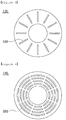
- the reintroduction channel 530 when the reintroduction channel 530 is formed as illustrated in FIG. 3 , the reintroduction channel may be formed to further narrow toward a center of the combustion chamber 100 in a lower portion of the combustion chamber 100, though not illustrated in the drawing.
- the reintroduction channel 530 may have a structure in which in a lower portion of the combustion chamber 100, the number of the reintroduction channels is decreased toward a center of the combustion chamber 100.
- the number of the reintroduction channels may be relatively reduced in a portion thereof in which a flow velocity for re-inflow into the combustion space 100a is relatively fast, and the number of the reintroduction channels may be relatively increased in a portion thereof in which a flow velocity for re-inflow into the combustion space 100a is relatively slow, thereby reducing an amount of clinker reintroduced into the combustion space 100a through the reintroduction channel 530.
- the reintroduction channels 530 illustrated in FIGS. 3 to 5 described above may have a proper size able to prevent the fuel F on the grate 130 from passing therethrough and being dropped.
- the combustor may further include a flow controlling member 540 configured to restrict a re-inflow of clinker in the clinker collection portion 520 to the combustion space 100a together with the combustion air A.
- the flow controlling member 540 is configured to control a flow structure of the combustion air in the clinker collection portion 520, a re-inflow of the clinker in the clinker collection portion 520 to the combustion space 100a, together with the combustion air A, may be restricted.
- the flow controlling member 540 may have a structure extending downwardly from a lower portion of the combustion chamber 100 inwardly of the clinker collection portion 520, and may also have a structure extending to be inclined downwardly toward a center of the combustion chamber 100.
- FIG. 6 is a view illustrating a combustion air flow structure in a case in which the flow controlling member 540 is not installed
- FIG. 6 is a view illustrating a combustion air flow structure in a case in which the flow controlling member 540 is installed.
- a direction of the combustion air A discharged from the combustion space 100a to the clinker collection portion 520 through the gap 510 may be changed along an inner surface of the clinker collection portion 520 as illustrated in (a) of FIG. 6 , and then, may be immediately reintroduced into the combustion space 100a through the reintroduction channel 530.
- the combustion air A may be guided by the flow controlling member 540 during a process in which the combustion air A is moved toward the reintroduction channel 530 after the direction of the combustion air is changed while colliding with an inner surface of the clinker collection portion 520, to thereby move toward a center of the combustion chamber 100 in a horizontal direction by a certain distance and then be reintroduced into the combustion space 100a through the reintroduction channel 530.
- the combustor according to an exemplary embodiment may further include a partition wall 600 formed in the gap 510 to be able to separate an air supply passage 510a and a clinker collection passage 510b from each other when the combustion air A provided by the lower air supply portion 320 is supplied to the combustion chamber 100 through the gap 510.
- the lower air supply portion 320 may be connected to a lower side portion of the combustion chamber 100, to supply the combustion air A in such a manner that the combustion air A may be in contact with the fuel F on an upper portion of the grate 130 to be burned and then may rise along a central portion of the combustion chamber 100.
- the gap 510 may be utilized as a passage through which the combustion air is introduced into the combustion space 100a.
- a flow of the combustion air A flowing out from the combustion space 100a to the clinker collection portion 520, and a flow of the combustion air A supplied from the lower air supply portion 320 to the combustion space 100a, may interfere with each other, and thus, clinker collecting efficiency of the clinker collection portion 520 may be lowered.
- the partition wall 600 may be installed in the gap 510.
- the partition wall 600 may have a structure in which the air supply passage 510a and the clinker collection passage 510b may be separated from each other in the gap 510, such that clinker may be collected by the clinker collecting portion 520 through the gap 510.
- the partition wall 600 may be disposed lengthwise in a vertical direction, but the layout structure thereof is not limited thereto.
- any layout structure of the partition wall to correspond to an adjacent structure may be used as long as the air supply passage 510a and the clinker collection passage 510b may be separated from each other in the gap 510.
- the combustor according to an exemplary embodiment may further include a check member 700 provided inside the clinker collection portion 520 as illustrated in FIG. 7 .
- the check member 700 may serve to block upwardly-reverse passage of the clinker having passed downwardly, and in detail, may have a structure in which a plurality of through holes 700a having a downwardly-narrowed shape are formed.
- the clinker collection efficiency of the clinker collection portion 520 may be increased by the check member 700 configured as described above.
- water may be received in a lower portion of the clinker collection portion 520 in such a manner that clinker may be deposited therein.
- the clinker may not be easily separated by attraction of water, and furthermore, when the clinker is immersed in the water, the clinker may not be influenced by a flow of the combustion air A at all, and thus, clinker collection efficiency of the clinker collection portion 520 may be further enhanced.
- the reintroduction channel 530 may be configured to pass through the grate 130 from the clinker collecting portion 520 to the combustion space 100a, such that the combustion air A having been discharged from the combustion space 100a to the clinker collection portion 520 through the gap 510 may be reintroduced into the combustion space 100a.
- clinker removal efficiency of the combustion space 100a may be increased.
Landscapes
- Engineering & Computer Science (AREA)
- Physics & Mathematics (AREA)
- Chemical & Material Sciences (AREA)
- Combustion & Propulsion (AREA)
- Thermal Sciences (AREA)
- Mechanical Engineering (AREA)
- General Engineering & Computer Science (AREA)
- Solid-Fuel Combustion (AREA)
- Air Supply (AREA)
Abstract
Description
- The present disclosure relates to a combustor, and more particularly, to a combustor recovering combustion heat generated by burning solid fuel in a combustion chamber to use recovered heat as energy.
- Generally, in industrial facilities requiring industrial hot water, steam, or high temperature gas, combustors generating heat energy by igniting and burning fuel in combustion chambers are utilized to obtain thermal energy. As fuel used in such combustors, solid fuel, obtained from domestic waste, and the like, has widely been used in view of economy and recycling resources.
- In the course of burning solid fuel in such combustors, clinker, generated by the combustion, is collected in clinker collection portions communicating with lower side portions of combustion chambers to be removed from the combustion chambers.
- However, clinker is collected in clinker collection portions in flowing combustion air. In this case, since combustion air may not smoothly flow out from a combustion space into the clinker collection portions, efficiency of clinker removal from the combustion space may be deteriorated.
- An aspect of the present disclosure is to provide a combustor, in which removal efficiency of clinker may be increased by smoothly discharging combustion air from a combustion space to a clinker collection portion.
- According to an aspect of the present disclosure, a combustor includes a combustion chamber including a grate therein and a combustion space formed above the grate; a fuel supply portion downwardly connected to a central portion of the grate to supply fuel to an upper portion of the grate; an air supply part connected to a side portion of the combustion chamber to be inclined with respect to a horizontal plane, to supply combustion air such that the combustion air rotates in the combustion space; a clinker collection portion downwardly communicating with a gap formed between an inner wall of the combustion chamber and the grate, to collect clinker generated by combustion of fuel performed in the combustion space, in the clinker collection portion through the gap; and a reintroduction channel passing through the grate from the clinker collection portion to the combustion space, such that the combustion air, having flowed from the combustion space to the clinker collection portion through the gap, is reintroduced into the combustion space.
- The reintroduction channel may be provided as a plurality of reintroduction channels, and may have a cross-sectional area decreasing toward a central portion of the combustion chamber in a lower portion of the combustion chamber.
- The reintroduction channel may be provided as a plurality of reintroduction channels, and the number of the plurality of reintroduction channels may be reduced toward a central portion of the combustion chamber in a lower portion of the combustion chamber.
- The combustor may further include a flow controlling member controlling a flow structure of the combustion air in the clinker collection portion, to restrict the clinker in the clinker collection portion from being reintroduced into the combustion space together with the combustion air.
- In this case, the flow controlling member may be configured to extend downwardly from a lower portion of the combustion chamber to an inside of the clinker collection portion.
- In this case, the flow controlling member may extend downwardly, toward a center of the combustion chamber.
- The combustor may further include a partition wall configured to be able to separate an air supply passage and a clinker collection passage from each other in the gap, in such a manner that the clinker is collected in the clinker collection portion through the gap when the combustion air provided by the air supply part is supplied into the combustion chamber through the gap.
- The combustor may further include a check member provided inside the clinker collection portion and configured to have a through hole having a downwardly-narrowed shape to block upwardly reverse passage of the clinker having passed downwardly.
- The clinker collection portion may accommodate water in a lower portion thereof, such that the clinker is deposited in the water.
- The air supply part may be configured to be connected to an outer wall of the combustion chamber, spaced apart from the inner wall while surrounding the inner wall, in such a manner that the combustion air rotates along an external surface of the inner wall of the combustion chamber, and then, is introduced into the combustion space through an inlet.
- The air supply part may include an upper air supply portion connected to an upper side portion of the combustion chamber to supply the combustion air in such a manner that the combustion air rotates downwardly in the combustion space; and a lower air supply portion connected to a lower side portion of the combustion chamber to supply combustion air in such a manner that the combustion air is in contact with the fuel on an upper portion of the grate to be burned and then rises along a central portion of the combustion chamber.
- The combustor may further include a guide member having a downwardly-opening structure and disposed to protrude from an inlet, through which the combustion air is introduced into the combustion space, inwardly of the combustion space, to guide the combustion air in such a manner that the combustion air rotates downwardly in the combustion space along the inner wall of the combustion chamber.
- The grate may be rotationally driven, based on the fuel supply portion.
- The fuel supply portion may pass through the grate to protrude into the combustion space, and may be configured to have a screw form to continuously supply the fuel.
- The fuel supply portion may pass through the grate to protrude into the combustion space, and may be provided with a blocking member, having a downwardly enlarged diameter and mounted on an end portion of the fuel supply portion, adjacent to the combustion space, to distribute the fuel laterally while blocking an upward movement of the fuel.
- The combustion chamber may have a frustoconical shape, in which an upper portion is relatively narrow and a lower portion is relatively wide.
- In the case of a combustor according to an aspect of the present disclosure, a reintroduction channel may be configured to pass through a grate from a clinker collection portion to a combustion space, such that combustion air discharged from the combustion space to the clinker collection portion through a gap may be reintroduced into the combustion space. Thus, as the combustion air may be smoothly discharged to the clinker collection portion from the combustion space, the efficiency of removing clinker from a combustion space may be increased.
-
-
FIG. 1 is a view illustrating an interior of a combustor according to an exemplary embodiment in the present disclosure. -
FIG. 2 is a view illustrating an interior of a combustor according to another exemplary embodiment in the present disclosure. -
FIG. 3 is a plan view of a lower grate in the combustors ofFIGS. 1 and2 . -
FIG. 4 is a view illustrating another embodiment of the grate illustrated inFIG. 3 . -
FIG. 5 is a view illustrating another embodiment of the grate illustrated inFIG. 3 .
(a) ofFIG. 6 is a view illustrating a structure in which combustion air flows in a case in which a flow controlling member is not provided in a clinker collection portion in the combustors ofFIGS. 1 and2 , and (b) ofFIG. 6 is a view illustrating a structure in which combustion air flows when a flow controlling member is installed in a clinker collection portion in the combustors ofFIGS. 1 and2 . -
FIG. 7 is a view illustrating a check member installed in a clinker collection portion in the combustors ofFIGS. 1 and2 . - Hereinafter, embodiments of the present disclosure will be described with reference to the accompanying drawings. In adding reference numerals to constituent elements of respective drawings, the same constituent elements are denoted by the same reference numerals even in the case in which they are shown in different drawings. In the following description of the present disclosure, a detailed description of functions and configurations below, known in the art, will be omitted in a case in which a subject matter of the invention is rather unclear.
-
FIG. 1 is a view illustrating an interior of a combustor according to an exemplary embodiment, andFIG. 2 is a view illustrating an interior of a combustor according to another exemplary embodiment. - Referring to the drawings, a combustor according to an exemplary embodiment may include a
combustion chamber 100 in which a fuel F, for example, a solid-type fuel, is burned, afuel supply portion 200 supplying the fuel F to thecombustion chamber 100, and an air supply part supplying combustion air A to thecombustion chamber 100, and as main constituent characteristics, may include aclinker collection portion 520 in which clinker generated by combustion of the fuel F in thecombustion space 100a is collected, and areintroduction channel 530 passing through agrate 130 from theclinker collection portion 520 to thecombustion space 100a. For example, the clinker may include ash as a remaining material after the fuel is burned. - In this case, the
combustion space 100a may be formed in thecombustion chamber 100, thegrate 130 may be installed in a lower portion of thecombustion space 100a, and anoutlet 100c may be formed in an upper portion thereof. In this case, thegrate 130 may be configured to have the fuel F seated thereon and configured to be provided with thefuel supply portion 200 downwardly connected to a central portion of the grate. - For example, the
combustion chamber 100 may have a frustoconical shape, in which an upper portion is relatively narrow and a lower portion is relatively wide, which may be selected as a stable structure including a downward-rotating flow of the combustion air A supplied to thecombustion chamber 100 to be described below, in terms of resistance thereof. In addition, this stable structure may be an efficient structure in which an unnecessary inner corner space in an angled section is removed in terms of a gas flow path. - The
grate 130 may be rotatably driven around thefuel supply portion 200 . As an example, thegrate 130 may be directly connected to a driving member to be rotationally driven. As another example, thegrate 130 may be installed on an upper surface of a turntable 140 (seeFIG. 2 ), and when a driving member rotates theturntable 140, the grate may rotate in conjunction therewith. In this case, the direct connection structure of the driving member to the grate and the connection structure through theturntable 140 may also be replaced by any structures of the related art, of course. - In addition, the
fuel supply portion 200 may be downwardly connected to a central portion of thegrate 130 to have a structure of supplying the fuel F to an upper portion of thegrate 130. As an example, thefuel supply portion 200 may pass through thegrate 130 to protrude into thecombustion space 100a, and may be configured to have a screw form such that the fuel F may be continuously supplied by ascrew 210. - In addition, a blocking
member 220 having a downwardly enlarged diameter may be mounted on an end portion of thefuel supply portion 200 adjacent to the combustion space 110a, to distribute the fuel F laterally while blocking an upward movement of the fuel F. - On the other hand, the air supply part may be connected to a side of the
combustion chamber 100 to supply the combustion air A into thecombustion chamber 100, and in detail, may be configured to include an upperair supply portion 310 and a lowerair supply portion 320. The upperair supply portion 310 and the lowerair supply portion 320 may be determined by a relative positional difference therebetween, and specific connection positions thereof connected to the side of thecombustion chamber 100 are not particularly limited. - In this case, the upper
air supply portion 310 and the lowerair supply portion 320 may be configured to be able to have a structure in which the combustion air A may be supplied to rotate along aninner wall 110 of thecombustion chamber 100. As an example, as illustrated inFIG. 3 , the upperair supply portion 310 may be connected to a side of thecombustion chamber 100, to be inclined on a horizontal plane. As the combustion air A supplied through the upperair supply portion 310 may descend while rotating along theinner wall 110 of thecombustion chamber 100, in thecombustion space 100a, the combustion air A may be preheated before reaching the fuel F on thegrate 130. Thus, combustion efficiency may be increased. Theinner wall 110 may be blocked from a high-temperature distribution portion extending in an upward direction from a central portion of thecombustion chamber 100 toward theoutlet 100c, thereby lowering a temperature of theinner wall 110 of thecombustion chamber 100. - The lower
air supply portion 320 may be connected to a lower side portion of thecombustion chamber 100 to supply the combustion air A, in such a manner that the combustion air A may contact the fuel F on thegrate 130 to be fired and then rise along a central portion of thecombustion chamber 100. - In addition, the upper
air supply portion 310 of the air supply part may be configured to be connected to anouter wall 120 of thecombustion chamber 100, spaced apart from theinner wall 110 while surrounding theinner wall 110, in such a manner that the combustion air A may rotate along an external surface of theinner wall 110 of thecombustion chamber 100, and then, may be introduced into thecombustion space 100a through aninlet 100b. - Thus, the combustion air A supplied through the upper
air supply portion 310 may cool theinner wall 110 while rotating upwardly along the external surface of theinner wall 110 of thecombustion chamber 100, and then, may be introduced into thecombustion space 100a through theinlet 100b, to be preheated while rotating downwardly. - In addition, as an example as illustrated in
FIG. 2 , the combustion air A supplied through the lowerair supply portion 320 may cool a lower portion of theinner wall 110, while rotating downwardly along an external surface of the lower portion of theinner wall 110 of thecombustion chamber 100, before being introduced into a side-lower portion of thecombustion space 100a. - The combustor according to an exemplary embodiment may further include a
guide member 400 guiding the combustion air A supplied by the air supply part to rotate downwardly inside thecombustion chamber 100, to cool theinner wall 110 of thecombustion chamber 100 together with the preheating of the combustion air A. - Here, a rotating flow structure of the combustion air A supplied to the
combustion space 100a through the upperair supply portion 310 of the air supply part as illustrated in the drawings will be described below in detail. - In detail, describing the upper
air supply portion 310 as an example, as the upperair supply portion 310 may be connected to a side portion of thecombustion chamber 100, to be inclined with respect to a horizontal plane, the combustion air A may have rotational force when the combustion air A is introduced into thecombustion space 100a through theinlet 100b. In detail, the combustion air A may pass through theouter wall 120 and theinner wall 110 of thecombustion chamber 100, and then, may be introduced into thecombustion space 100a through theinlet 100b. Even when the combustion air is introduced into thecombustion space 100a after the flow of the combustion air as described above, the rotational force of the combustion air A may also be maintained. - The combustion air A, having the maintained rotational force, even in the
combustion space 100a, as described above, may be pushed by a subsequent continuous air introduced subsequently and continuously, and a portion of this combustion air may rotate while descending, but remaining combustion air A may be intaken by high-temperature combustion gas reacting with and fired by the fuel F and flowing upwardly toward theoutlet 100c, and thus, may be moved to a central portion or an upper portion of thecombustion chamber 100. - Thus, according to an exemplary embodiment in the present disclosure, the combustion air A may be guided by the
guide member 400, such that the combustion air A having the maintained rotational force may rotate downwardly along theinner wall 110 of thecombustion chamber 100 in thecombustion space 100a, other than moving toward a central portion or an upper portion of thecombustion chamber 100. - In this case, the
guide member 400 may have a structure disposed to protrude from theinlet 100b, through which the combustion air A is introduced into thecombustion space 100a, inwardly of thecombustion space 100a, while having a downwardly-opening structure. In detail, theguide member 400 may include anupper guide plate 410 extending from an upper structure of theinlet 100b in thecombustion chamber 100, inwardly of thecombustion chamber 100, and a side guide plate 411 extending downwardly from theupper guide plate 410 and spaced apart from theinner wall 110 of thecombustion chamber 100. In this case, the side guide plate 411 may be arranged to be spaced apart from theinner wall 110 of thecombustion chamber 100 by an appropriate interval, and theupper guide plate 410 may have a structure extended from an upper end portion of a position of theinlet 100b of thecombustion space 100a toward the side guide plate 411, in thecombustion chamber 100. For example, as illustrated in the drawings, in a case in which a flange structure is present above theinner wall 110 of thecombustion chamber 100, and theinlet 100b of thecombustion space 100a is present between the flange structure and theinner wall 110, the flange structure may function as an upper guide plate 412. - In addition, according to an exemplary embodiment, a branching portion configured to provide an amount of combustion air greater than that of the lower
air supply portion 320 may further be provided in the upperair supply portion 310 supplying the combustion air A to an upper portion of thecombustion chamber 100 such that the combustion air A may rotate downwardly as described above. As the amount of combustion air supplied to the upperair supply portion 310 is increased by the branching portion, preheating of the combustion air A and an effect of cooling theinner wall 110 of thecombustion chamber 100 may be enhanced. - In detail, the branching portion may be provided with a
branch wall 341 for a branch flow of the combustion air A, disposed in anair supply line 330 connected, as one flow path, to the upperair supply portion 310 and the lowerair supply portion 320. A pivotingbar 342 may be mounted on an end portion of thebranch wall 341 to adjust an amount of combustion air flowing to the upperair supply portion 310 and the lowerair supply portion 320, respectively. The pivotingbar 342 may have a structure interlocked with a driving unit providing driving force to the pivotingbar 342 to pivot the pivotingbar 342, though the structure is not illustrated in the drawings. - On the other hand, as main constituent characteristics, the combustor according to an exemplary embodiment may include the
clinker collection portion 520, in which clinker generated by combustion of the fuel F in thecombustion space 100a is collected through agap 510, and thereintroduction channel 530 configured to allow the combustion air A discharged from thecombustion space 100a to theclinker collection portion 520 through thegap 510 to be reintroduced into thecombustion space 100a, to increase efficiency of removing clinker from thecombustion space 100a. - In detail, the
clinker collection portion 520 may downwardly communicate with thegap 510 formed between theinner wall 110 of thecombustion chamber 100 and thegrate 130, and may serve to collect clinker generated by combustion of the fuel F in thecombustion space 100a, throughgap 510. - In detail, the clinker, a material remaining after the combustion of the fuel F, may move by the combustion air A rotating downwardly in the
combustion space 100a, and thus, may be discharged from thecombustion space 100a through thegap 510 disposed on a lower edge of thecombustion space 100a and formed between thegrate 130 and theinner wall 110 of thecombustion chamber 100, to then be collected in theclinker collection portion 520. - As the
reintroduction channel 530 is configured to have a structure passing through thegrate 130 from theclinker collection portion 520 to thecombustion space 100a, the combustion air A discharged from thecombustion space 100a to theclinker collection portion 520 through thegap 510 may be reintroduced into thecombustion space 100a. - In this case, structures of the
combustion space 100a and theclinker collection portion 520, in which the combustion air A flows, will be described below in detail. For example, if only thegap 510 is a passage allowing the combustion air A to flow into and out of theclinker collection portion 520, the combustion air A may collide with combustion air A reintroduced into thecombustion space 100a through thegap 510 when the combustion air A is discharged from thecombustion space 100a to theclinker collection portion 520 through thegap 510. Thus, since an outflow of the combustion air A to theclinker collection portion 520 may not be smoothly performed, the clinker may not be efficiently collected in theclinker collection portion 520. - However, according to an exemplary embodiment, the
reintroduction channel 530 configured to allow the combustion air A to be reintroduced into thecombustion space 100a may be provided, in such a manner that the combustion air A may be smoothly discharged from thecombustion space 100a to theclinker collection portion 520, to increase efficiency of removing clinker from thecombustion space 100a. - In this case, the
reintroduction channel 530 may have a structure passing through thegrate 130 from theclinker collection portion 520 to thecombustion space 100a, and may be provided as a passage separate from thegap 510 while being formed to pass through thegrate 130 in a lower portion of thecombustion chamber 100, and a detailed structure thereof in the present disclosure is not particularly limited. - As illustrated in the drawings, the
reintroduction channel 530 may be provided as at least one or more channels, for example, a plurality of reintroduction channels may be formed in a central circumferential portion of a lower portion of thecombustion chamber 100. - On the other hand, although the combustion air A is reintroduced into the
combustion space 100a through thereintroduction channel 530, a portion of clinker may also be reintroduced into thecombustion space 100a together with the combustion air A in the re-inflow process as described above. In detail, as the combustion air A is away from thegap 510 in theclinker collection portion 520 in terms of a flow structure of combustion air, for example, the combustion air A flows from a lower portion of thecombustion chamber 100 toward a central portion thereof, a flow velocity of the combustion air reintroduced into thecombustion space 100a through thereintroduction channel 530 may increase, and as the flow velocity increases, clinker may be easily moved into thecombustion space 100a by the combustion air A. - Thus, as illustrated in
FIG. 4 , thereintroduction channel 530 may have a structure in which cross-sectional areas thereof are decreased toward a center of thecombustion chamber 100 in a lower portion of thecombustion chamber 100, by way of example. Thus, the size of a cross-sectional area of the reintroduction channel may be relatively reduced in a portion thereof in which a flow velocity for re-inflow into thecombustion space 100a is relatively fast, and the size of a cross-sectional area of the reintroduction channel may be relatively increased in a portion thereof in which a flow velocity for re-inflow into thecombustion space 100a is relatively slow, thereby reducing an amount of clinker reintroduced into thecombustion space 100a through thereintroduction channel 530. For example, the cross-sectional area of thereintroduction channel 530 refers to a cross-sectional area at an angle at which a flow rate is controlled at the time of size change, and as an example, may refer to a transversal cross-sectional area in the drawing. - Further, for example, when the
reintroduction channel 530 is formed as illustrated inFIG. 3 , the reintroduction channel may be formed to further narrow toward a center of thecombustion chamber 100 in a lower portion of thecombustion chamber 100, though not illustrated in the drawing. - In addition, as another example as illustrated in
FIG. 5 , thereintroduction channel 530 may have a structure in which in a lower portion of thecombustion chamber 100, the number of the reintroduction channels is decreased toward a center of thecombustion chamber 100. Thus, the number of the reintroduction channels may be relatively reduced in a portion thereof in which a flow velocity for re-inflow into thecombustion space 100a is relatively fast, and the number of the reintroduction channels may be relatively increased in a portion thereof in which a flow velocity for re-inflow into thecombustion space 100a is relatively slow, thereby reducing an amount of clinker reintroduced into thecombustion space 100a through thereintroduction channel 530. - For example, the
reintroduction channels 530 illustrated inFIGS. 3 to 5 described above may have a proper size able to prevent the fuel F on thegrate 130 from passing therethrough and being dropped. - In addition, as illustrated in (b) of
FIG. 6 , the combustor according to an exemplary embodiment may further include aflow controlling member 540 configured to restrict a re-inflow of clinker in theclinker collection portion 520 to thecombustion space 100a together with the combustion air A. - As the
flow controlling member 540 is configured to control a flow structure of the combustion air in theclinker collection portion 520, a re-inflow of the clinker in theclinker collection portion 520 to thecombustion space 100a, together with the combustion air A, may be restricted. - In detail, as illustrated in (b) of
FIG. 6 , theflow controlling member 540 may have a structure extending downwardly from a lower portion of thecombustion chamber 100 inwardly of theclinker collection portion 520, and may also have a structure extending to be inclined downwardly toward a center of thecombustion chamber 100. - In this case, a flow structure of combustion air in the
clinker collection portion 520 will be described below with reference toFIG. 6 . First, (a) ofFIG. 6 is a view illustrating a combustion air flow structure in a case in which theflow controlling member 540 is not installed, and (b) ofFIG. 6 is a view illustrating a combustion air flow structure in a case in which theflow controlling member 540 is installed. - In this case, a direction of the combustion air A discharged from the
combustion space 100a to theclinker collection portion 520 through thegap 510 may be changed along an inner surface of theclinker collection portion 520 as illustrated in (a) ofFIG. 6 , and then, may be immediately reintroduced into thecombustion space 100a through thereintroduction channel 530. On the other hand, in (b) ofFIG. 6 , the combustion air A may be guided by theflow controlling member 540 during a process in which the combustion air A is moved toward thereintroduction channel 530 after the direction of the combustion air is changed while colliding with an inner surface of theclinker collection portion 520, to thereby move toward a center of thecombustion chamber 100 in a horizontal direction by a certain distance and then be reintroduced into thecombustion space 100a through thereintroduction channel 530. - As described above, as illustrated in (b) of
FIG. 6 , as the direction of the combustion air A is changed by theflow controlling member 540 in a horizontal direction, without flowing of the combustion air toward thereintroduction channel 530 via immediate rising of the combustion air at a high speed in theclinker collection portion 520, a flow velocity of the combustion air A may be reduced, and further, a flow length may be increased. In addition, as vortex intensity is reduced, rather than extending a flow diameter of the combustion air rotating below thegap 510 in a vertical direction, clinker flowing along with the combustion air A may be effectively separated from the combustion air A by self weight, and thus, clinker collecting efficiency of theclinker collection portion 520 may be increased. - On the other hand, the combustor according to an exemplary embodiment may further include a
partition wall 600 formed in thegap 510 to be able to separate anair supply passage 510a and aclinker collection passage 510b from each other when the combustion air A provided by the lowerair supply portion 320 is supplied to thecombustion chamber 100 through thegap 510. - The lower
air supply portion 320 may be connected to a lower side portion of thecombustion chamber 100, to supply the combustion air A in such a manner that the combustion air A may be in contact with the fuel F on an upper portion of thegrate 130 to be burned and then may rise along a central portion of thecombustion chamber 100. In this case, as illustrated inFIG. 1 , thegap 510 may be utilized as a passage through which the combustion air is introduced into thecombustion space 100a. - In this case, in the
gap 510, a flow of the combustion air A flowing out from thecombustion space 100a to theclinker collection portion 520, and a flow of the combustion air A supplied from the lowerair supply portion 320 to thecombustion space 100a, may interfere with each other, and thus, clinker collecting efficiency of theclinker collection portion 520 may be lowered. In order to prevent the clinker collecting efficiency of theclinker collection portion 520 from being deteriorated, thepartition wall 600 may be installed in thegap 510. - In detail, the
partition wall 600 may have a structure in which theair supply passage 510a and theclinker collection passage 510b may be separated from each other in thegap 510, such that clinker may be collected by theclinker collecting portion 520 through thegap 510. As an example, as illustrated in the drawings, thepartition wall 600 may be disposed lengthwise in a vertical direction, but the layout structure thereof is not limited thereto. For example, any layout structure of the partition wall to correspond to an adjacent structure may be used as long as theair supply passage 510a and theclinker collection passage 510b may be separated from each other in thegap 510. - In addition, the combustor according to an exemplary embodiment may further include a
check member 700 provided inside theclinker collection portion 520 as illustrated inFIG. 7 . - The
check member 700 may serve to block upwardly-reverse passage of the clinker having passed downwardly, and in detail, may have a structure in which a plurality of throughholes 700a having a downwardly-narrowed shape are formed. - In the case of the downwardly-narrowed structure of the through
hole 700a of thecheck member 700, in which an upper portion of the through hole is relatively wide and a width of the through hole is gradually reduced downwardly, clinker may be easily introduced through a relatively-large upper opening of the throughhole 700a, such that the clinker may smoothly pass downwardly through the throughhole 700a, while in the case in which the clinker passes through the throughhole 700a upwardly in a reverse direction, the clinker may not easily pass through a relatively-narrow lower opening of the through hole. Thus, most of the clinker may not pass upwardly through the throughhole 700a. - The clinker collection efficiency of the
clinker collection portion 520 may be increased by thecheck member 700 configured as described above. - In addition, although not illustrated in the drawings, water may be received in a lower portion of the
clinker collection portion 520 in such a manner that clinker may be deposited therein. For example, when the clinker is seated in the water, the clinker may not be easily separated by attraction of water, and furthermore, when the clinker is immersed in the water, the clinker may not be influenced by a flow of the combustion air A at all, and thus, clinker collection efficiency of theclinker collection portion 520 may be further enhanced. - As a result, as described above, according to an exemplary embodiment in the present disclosure, the
reintroduction channel 530 may be configured to pass through thegrate 130 from theclinker collecting portion 520 to thecombustion space 100a, such that the combustion air A having been discharged from thecombustion space 100a to theclinker collection portion 520 through thegap 510 may be reintroduced into thecombustion space 100a. Thus, as the combustion air A may smoothly flow from thecombustion space 100a to theclinker collection portion 520, clinker removal efficiency of thecombustion space 100a may be increased. - While exemplary embodiments have been shown and described above, it will be apparent to those skilled in the art that modifications and variations could be made without departing from the scope of the present invention as defined by the appended claims.
Claims (16)
- A combustor comprising:a combustion chamber including a grate therein and a combustion space formed above the grate;a fuel supply portion downwardly connected to a central portion of the grate to supply fuel to an upper portion of the grate;an air supply part connected to a side portion of the combustion chamber to be inclined with respect to a horizontal plane, to supply combustion air such that the combustion air rotates in the combustion space;a clinker collection portion downwardly communicating with a gap formed between an inner wall of the combustion chamber and the grate, to collect clinker generated by combustion of fuel performed in the combustion space, in the clinker collection portion through the gap; anda reintroduction channel passing through the grate from the clinker collection portion to the combustion space, such that the combustion air, having flowed from the combustion space to the clinker collection portion through the gap, is reintroduced into the combustion space.
- The combustor of claim 1, wherein the reintroduction channel is provided as a plurality of reintroduction channels, and has a cross-sectional area decreasing toward a central portion of the combustion chamber in a lower portion of the combustion chamber.
- The combustor of claim 1, wherein the reintroduction channel is provided as a plurality of reintroduction channels, and the number of the plurality of reintroduction channels is reduced toward a central portion of the combustion chamber in a lower portion of the combustion chamber.
- The combustor of claim 1, further comprising a flow controlling member controlling a flow structure of the combustion air in the clinker collection portion, to restrict the clinker in the clinker collection portion from being reintroduced into the combustion space together with the combustion air.
- The combustor of claim 4, wherein the flow controlling member is configured to extend downwardly from a lower portion of the combustion chamber to an inside of the clinker collection portion.
- The combustor of claim 5, wherein the flow controlling member extends downwardly, toward a center of the combustion chamber.
- The combustor of claim 1, further comprising a partition wall configured to be able to separate an air supply passage and a clinker collection passage from each other in the gap, in such a manner that the clinker is collected in the clinker collection portion through the gap when the combustion air provided by the air supply part is supplied to the combustion chamber through the gap.
- The combustor of claim 1, further comprising a check member provided inside the clinker collection portion and configured to have a through hole having a downwardly-narrowed shape to block upwardly reverse passage of the clinker having passed downwardly.
- The combustor of any one of claims 1 to 8, wherein the clinker collection portion accommodates water in a lower portion thereof, such that the clinker is deposited in the water.
- The combustor of claim 1, wherein the air supply part is configured to be connected to an outer wall of the combustion chamber, spaced apart from the inner wall while surrounding the inner wall, in such a manner that the combustion air rotates along an external surface of the inner wall of the combustion chamber, and then, is introduced into the combustion space through an inlet.
- The combustor of claim 1, wherein the air supply part comprises:an upper air supply portion connected to an upper side portion of the combustion chamber to supply the combustion air in such a manner that the combustion air rotates downwardly in the combustion space; anda lower air supply portion connected to a lower side portion of the combustion chamber to supply combustion air in such a manner that the combustion air is in contact with the fuel on an upper portion of the grate to be burned and then rises along a central portion of the combustion chamber.
- The combustor of claim 1, further comprising a guide member having a downwardly-opening structure and disposed to protrude from an inlet, through which the combustion air is introduced into the combustion space, inwardly of the combustion space, to guide the combustion air in such a manner that the combustion air rotates downwardly in the combustion space along the inner wall of the combustion chamber.
- The combustor of claim 1, wherein the grate is rotationally driven, based on the fuel supply portion.
- The combustor of claim 1, wherein the fuel supply portion passes through the grate to protrude into the combustion space, and is configured to have a screw form to continuously supply the fuel.
- The combustor of claim 1, wherein the fuel supply portion passes through the grate to protrude into the combustion space, and is provided with a blocking member, having a downwardly enlarged diameter and mounted on an end portion of the fuel supply portion, adjacent to the combustion space, to distribute the fuel laterally while blocking an upward movement of the fuel.
- The combustor of claim 1, wherein the combustion chamber has a frustoconical shape, in which an upper portion is relatively narrow and a lower portion is relatively wide.
Applications Claiming Priority (2)
| Application Number | Priority Date | Filing Date | Title |
|---|---|---|---|
| KR1020150080629A KR101726047B1 (en) | 2015-06-08 | 2015-06-08 | Combustor |
| PCT/KR2015/008000 WO2016199977A1 (en) | 2015-06-08 | 2015-07-30 | Combustor |
Publications (2)
| Publication Number | Publication Date |
|---|---|
| EP3306191A1 true EP3306191A1 (en) | 2018-04-11 |
| EP3306191A4 EP3306191A4 (en) | 2018-06-20 |
Family
ID=57503934
Family Applications (1)
| Application Number | Title | Priority Date | Filing Date |
|---|---|---|---|
| EP15895045.1A Withdrawn EP3306191A4 (en) | 2015-06-08 | 2015-07-30 | Combustor |
Country Status (10)
| Country | Link |
|---|---|
| US (1) | US20180163961A1 (en) |
| EP (1) | EP3306191A4 (en) |
| JP (1) | JP6574495B2 (en) |
| KR (1) | KR101726047B1 (en) |
| CN (1) | CN107690556B (en) |
| AU (1) | AU2015398367B2 (en) |
| BR (1) | BR112017025992A2 (en) |
| CA (1) | CA2987567A1 (en) |
| PH (1) | PH12017502227A1 (en) |
| WO (1) | WO2016199977A1 (en) |
Families Citing this family (8)
| Publication number | Priority date | Publication date | Assignee | Title |
|---|---|---|---|---|
| KR101879089B1 (en) * | 2016-12-22 | 2018-07-16 | 주식회사 포스코 | Combustor |
| KR101895069B1 (en) * | 2017-04-25 | 2018-09-04 | 주식회사 포스코 | Fuel feeding apparatus for combustor and fuel feeding method using the same |
| KR101949052B1 (en) | 2017-12-21 | 2019-02-15 | 주식회사 포스코 | Combustor |
| KR102020403B1 (en) * | 2017-12-21 | 2019-09-10 | 주식회사 포스코 | Fuel supply unit and combustor having thereof |
| KR102020408B1 (en) * | 2017-12-21 | 2019-09-10 | 주식회사 포스코 | Fuel supply unit and combustor having thereof |
| CN110173897A (en) * | 2019-07-04 | 2019-08-27 | 广东省众骋热能科技有限公司 | A kind of combustion heat-exchange device with multiple-stage adiabatic structure |
| CN117255918A (en) * | 2021-03-01 | 2023-12-19 | 爱拓股份有限公司 | Solid fuel combustion device |
| CN115638431B (en) * | 2022-10-10 | 2023-06-02 | 嘉善东都节能技术有限公司 | Flue gas waste heat recovery structure and method applied to biomass boiler |
Family Cites Families (18)
| Publication number | Priority date | Publication date | Assignee | Title |
|---|---|---|---|---|
| US1957583A (en) * | 1931-08-07 | 1934-05-08 | Westinghouse Electric & Mfg Co | Combustion apparatus |
| JPS53955Y2 (en) * | 1973-01-23 | 1978-01-12 | ||
| JPS5066068A (en) * | 1973-10-18 | 1975-06-04 | ||
| JPS5896912A (en) * | 1981-12-03 | 1983-06-09 | Obanaya Sangyo:Kk | Rotary hearth in excrement gas generating furnace |
| JPH0379021U (en) * | 1989-11-27 | 1991-08-12 | ||
| CN2601125Y (en) * | 2003-02-25 | 2004-01-28 | 盛国祝 | Flue dust remover |
| KR100821124B1 (en) * | 2007-11-16 | 2008-04-14 | 에너원 주식회사 | Heat recovery combustion device |
| KR100890682B1 (en) * | 2008-06-09 | 2009-03-26 | 김정길 | Heat recovery combustion device using solid fuel |
| KR101041461B1 (en) * | 2008-09-18 | 2011-06-16 | 일도바이오테크주식회사 | Complete combustion device of small solid fuel burner |
| KR100907269B1 (en) * | 2008-11-18 | 2009-07-14 | 김지원 | Centrifugal Continuous Combustion Device and Combustion Method |
| JP2011226691A (en) * | 2010-04-19 | 2011-11-10 | Tabata Sangyo:Kk | Solid fuel combustion device and boiler device |
| TR201005272A2 (en) * | 2010-06-29 | 2011-10-21 | Fai̇k Özyaman Şenol | A solid fuel unit capable of burning solid fuels with volatile gases. |
| JP5261467B2 (en) * | 2010-07-22 | 2013-08-14 | 相權 金 | Combustion device with improved thermal efficiency |
| KR101228345B1 (en) * | 2010-08-17 | 2013-01-31 | 김상권 | Combustion apparatus with improved combustion efficiency |
| CN102345850B (en) * | 2010-07-22 | 2014-02-26 | 创意能源控股有限公司 | Thermal recovery system with improved thermal efficiency and thermoelectric combined production system equipped with the thermal recovery system |
| JP5774879B2 (en) * | 2011-03-07 | 2015-09-09 | 株式会社御池鐵工所 | Hearth structure and combustion furnace |
| KR101304095B1 (en) * | 2011-12-08 | 2013-09-05 | 김홍규 | Water Tube Steam Boiler Using Wood Pellet |
| CN204141565U (en) * | 2014-08-06 | 2015-02-04 | 成都王安产业有限公司 | A kind of downdraf combustion-type heat energy machine |
-
2015
- 2015-06-08 KR KR1020150080629A patent/KR101726047B1/en active Active
- 2015-07-30 WO PCT/KR2015/008000 patent/WO2016199977A1/en not_active Ceased
- 2015-07-30 JP JP2017563340A patent/JP6574495B2/en not_active Expired - Fee Related
- 2015-07-30 US US15/578,611 patent/US20180163961A1/en not_active Abandoned
- 2015-07-30 CN CN201580080807.3A patent/CN107690556B/en not_active Expired - Fee Related
- 2015-07-30 CA CA2987567A patent/CA2987567A1/en not_active Abandoned
- 2015-07-30 AU AU2015398367A patent/AU2015398367B2/en not_active Expired - Fee Related
- 2015-07-30 BR BR112017025992A patent/BR112017025992A2/en not_active Application Discontinuation
- 2015-07-30 EP EP15895045.1A patent/EP3306191A4/en not_active Withdrawn
-
2017
- 2017-12-07 PH PH12017502227A patent/PH12017502227A1/en unknown
Also Published As
| Publication number | Publication date |
|---|---|
| PH12017502227A1 (en) | 2018-06-25 |
| BR112017025992A2 (en) | 2018-08-14 |
| US20180163961A1 (en) | 2018-06-14 |
| JP2018517112A (en) | 2018-06-28 |
| CA2987567A1 (en) | 2016-12-15 |
| EP3306191A4 (en) | 2018-06-20 |
| AU2015398367A1 (en) | 2018-01-25 |
| AU2015398367B2 (en) | 2019-04-18 |
| CN107690556B (en) | 2019-07-05 |
| KR101726047B1 (en) | 2017-04-27 |
| KR20160144543A (en) | 2016-12-19 |
| CN107690556A (en) | 2018-02-13 |
| JP6574495B2 (en) | 2019-09-11 |
| WO2016199977A1 (en) | 2016-12-15 |
Similar Documents
| Publication | Publication Date | Title |
|---|---|---|
| AU2015398367B2 (en) | Combustor | |
| EP2921776B1 (en) | Device for centrifugal combustion by area using flow of combustion air | |
| JP5349606B2 (en) | Circulating fluidized bed boiler | |
| RU2684007C2 (en) | Agglomerate cooler | |
| JP4460993B2 (en) | Dust collection cyclone with heat exchanger | |
| KR101767785B1 (en) | Combustor | |
| RU2536068C2 (en) | Rotary drum-type drier for plants for production of bitumen macadam with application of reusable materials | |
| KR101786304B1 (en) | Furnance of solid fuel | |
| JP2010144997A (en) | Exhaust heat recovery boiler | |
| KR100356925B1 (en) | raw-material heating apparatus | |
| CN102242928B (en) | Decelerating wear-resisting device and boiler furnace equipped therewith | |
| RU2552009C1 (en) | Mechanised grate-fired furnace | |
| KR101316162B1 (en) | Sintered ore cooling apparatus | |
| KR101778410B1 (en) | Combustor | |
| EP3321578A1 (en) | Combustor | |
| RU2534712C1 (en) | Afterburner for anode gases of aluminium electrolyser | |
| TWI309291B (en) | ||
| WO2000031483A1 (en) | Cooler for cooling of particulate material | |
| JP2019074258A (en) | Sediment treatment method | |
| UA105746C2 (en) | Swirling-type furnace | |
| JP6789786B2 (en) | Method of supporting rectifying plate of pulverized coal burner, boiler and pulverized coal burner | |
| EP2944875A1 (en) | Torsional combustion chamber | |
| CN104556746A (en) | T-shaped combustion beam for lime kiln | |
| RO116123B1 (en) | Ignition hearth with adjustable lamellar burner | |
| BRPI1101067B1 (en) | METHOD FOR BURNING SOLID FUEL IN A SOLID FUEL BOILER AND SOLID FUEL BOILER |
Legal Events
| Date | Code | Title | Description |
|---|---|---|---|
| STAA | Information on the status of an ep patent application or granted ep patent |
Free format text: STATUS: THE INTERNATIONAL PUBLICATION HAS BEEN MADE |
|
| PUAI | Public reference made under article 153(3) epc to a published international application that has entered the european phase |
Free format text: ORIGINAL CODE: 0009012 |
|
| STAA | Information on the status of an ep patent application or granted ep patent |
Free format text: STATUS: REQUEST FOR EXAMINATION WAS MADE |
|
| 17P | Request for examination filed |
Effective date: 20180105 |
|
| AK | Designated contracting states |
Kind code of ref document: A1 Designated state(s): AL AT BE BG CH CY CZ DE DK EE ES FI FR GB GR HR HU IE IS IT LI LT LU LV MC MK MT NL NO PL PT RO RS SE SI SK SM TR |
|
| AX | Request for extension of the european patent |
Extension state: BA ME |
|
| A4 | Supplementary search report drawn up and despatched |
Effective date: 20180524 |
|
| RIC1 | Information provided on ipc code assigned before grant |
Ipc: F23B 40/04 20060101ALI20180517BHEP Ipc: F23B 30/00 20060101AFI20180517BHEP Ipc: F23B 80/02 20060101ALI20180517BHEP |
|
| DAV | Request for validation of the european patent (deleted) | ||
| DAX | Request for extension of the european patent (deleted) | ||
| STAA | Information on the status of an ep patent application or granted ep patent |
Free format text: STATUS: THE APPLICATION IS DEEMED TO BE WITHDRAWN |
|
| 18D | Application deemed to be withdrawn |
Effective date: 20200201 |