EP3306097A1 - Air compression device - Google Patents
Air compression device Download PDFInfo
- Publication number
- EP3306097A1 EP3306097A1 EP16803186.2A EP16803186A EP3306097A1 EP 3306097 A1 EP3306097 A1 EP 3306097A1 EP 16803186 A EP16803186 A EP 16803186A EP 3306097 A1 EP3306097 A1 EP 3306097A1
- Authority
- EP
- European Patent Office
- Prior art keywords
- rib
- plate
- housing
- air
- compression device
- Prior art date
- Legal status (The legal status is an assumption and is not a legal conclusion. Google has not performed a legal analysis and makes no representation as to the accuracy of the status listed.)
- Granted
Links
Images








Classifications
-
- F—MECHANICAL ENGINEERING; LIGHTING; HEATING; WEAPONS; BLASTING
- F04—POSITIVE - DISPLACEMENT MACHINES FOR LIQUIDS; PUMPS FOR LIQUIDS OR ELASTIC FLUIDS
- F04C—ROTARY-PISTON, OR OSCILLATING-PISTON, POSITIVE-DISPLACEMENT MACHINES FOR LIQUIDS; ROTARY-PISTON, OR OSCILLATING-PISTON, POSITIVE-DISPLACEMENT PUMPS
- F04C29/00—Component parts, details or accessories of pumps or pumping installations, not provided for in groups F04C18/00 - F04C28/00
- F04C29/04—Heating; Cooling; Heat insulation
-
- B—PERFORMING OPERATIONS; TRANSPORTING
- B61—RAILWAYS
- B61C—LOCOMOTIVES; MOTOR RAILCARS
- B61C17/00—Arrangement or disposition of parts; Details or accessories not otherwise provided for; Use of control gear and control systems
-
- F—MECHANICAL ENGINEERING; LIGHTING; HEATING; WEAPONS; BLASTING
- F01—MACHINES OR ENGINES IN GENERAL; ENGINE PLANTS IN GENERAL; STEAM ENGINES
- F01C—ROTARY-PISTON OR OSCILLATING-PISTON MACHINES OR ENGINES
- F01C21/00—Component parts, details or accessories not provided for in groups F01C1/00 - F01C20/00
- F01C21/007—General arrangements of parts; Frames and supporting elements
-
- F—MECHANICAL ENGINEERING; LIGHTING; HEATING; WEAPONS; BLASTING
- F01—MACHINES OR ENGINES IN GENERAL; ENGINE PLANTS IN GENERAL; STEAM ENGINES
- F01C—ROTARY-PISTON OR OSCILLATING-PISTON MACHINES OR ENGINES
- F01C21/00—Component parts, details or accessories not provided for in groups F01C1/00 - F01C20/00
- F01C21/10—Outer members for co-operation with rotary pistons; Casings
-
- F—MECHANICAL ENGINEERING; LIGHTING; HEATING; WEAPONS; BLASTING
- F04—POSITIVE - DISPLACEMENT MACHINES FOR LIQUIDS; PUMPS FOR LIQUIDS OR ELASTIC FLUIDS
- F04B—POSITIVE-DISPLACEMENT MACHINES FOR LIQUIDS; PUMPS
- F04B39/00—Component parts, details, or accessories, of pumps or pumping systems specially adapted for elastic fluids, not otherwise provided for in, or of interest apart from, groups F04B25/00 - F04B37/00
- F04B39/0027—Pulsation and noise damping means
- F04B39/0044—Pulsation and noise damping means with vibration damping supports
-
- F—MECHANICAL ENGINEERING; LIGHTING; HEATING; WEAPONS; BLASTING
- F04—POSITIVE - DISPLACEMENT MACHINES FOR LIQUIDS; PUMPS FOR LIQUIDS OR ELASTIC FLUIDS
- F04B—POSITIVE-DISPLACEMENT MACHINES FOR LIQUIDS; PUMPS
- F04B39/00—Component parts, details, or accessories, of pumps or pumping systems specially adapted for elastic fluids, not otherwise provided for in, or of interest apart from, groups F04B25/00 - F04B37/00
- F04B39/12—Casings; Cylinders; Cylinder heads; Fluid connections
- F04B39/121—Casings
-
- F—MECHANICAL ENGINEERING; LIGHTING; HEATING; WEAPONS; BLASTING
- F04—POSITIVE - DISPLACEMENT MACHINES FOR LIQUIDS; PUMPS FOR LIQUIDS OR ELASTIC FLUIDS
- F04C—ROTARY-PISTON, OR OSCILLATING-PISTON, POSITIVE-DISPLACEMENT MACHINES FOR LIQUIDS; ROTARY-PISTON, OR OSCILLATING-PISTON, POSITIVE-DISPLACEMENT PUMPS
- F04C2230/00—Manufacture
- F04C2230/20—Manufacture essentially without removing material
- F04C2230/23—Manufacture essentially without removing material by permanently joining parts together
- F04C2230/231—Manufacture essentially without removing material by permanently joining parts together by welding
-
- F—MECHANICAL ENGINEERING; LIGHTING; HEATING; WEAPONS; BLASTING
- F04—POSITIVE - DISPLACEMENT MACHINES FOR LIQUIDS; PUMPS FOR LIQUIDS OR ELASTIC FLUIDS
- F04C—ROTARY-PISTON, OR OSCILLATING-PISTON, POSITIVE-DISPLACEMENT MACHINES FOR LIQUIDS; ROTARY-PISTON, OR OSCILLATING-PISTON, POSITIVE-DISPLACEMENT PUMPS
- F04C2240/00—Components
- F04C2240/30—Casings or housings
-
- F—MECHANICAL ENGINEERING; LIGHTING; HEATING; WEAPONS; BLASTING
- F04—POSITIVE - DISPLACEMENT MACHINES FOR LIQUIDS; PUMPS FOR LIQUIDS OR ELASTIC FLUIDS
- F04C—ROTARY-PISTON, OR OSCILLATING-PISTON, POSITIVE-DISPLACEMENT MACHINES FOR LIQUIDS; ROTARY-PISTON, OR OSCILLATING-PISTON, POSITIVE-DISPLACEMENT PUMPS
- F04C2270/00—Control; Monitoring or safety arrangements
- F04C2270/12—Vibration
Definitions
- the present invention relates to an air compression device which generates compressed air.
- An air compression device which generates compressed air is used for various uses.
- the compressed air generated by the air compression device mounted to a vehicle may be supplied to a brake device which applies braking force to the vehicle or to pneumatic equipment which opens and closes a door of a vehicle in some cases.
- Patent Literature 1 proposes an air compression device mounted to a railroad vehicle.
- the air compression device includes a housing in which a compression mechanism which compresses air is housed.
- a housing by which a compression mechanism is enclosed can appropriately protect the compression mechanism from a flipped stone or other flying objects during travel of a vehicle.
- the housing can prevent leakage of a sound generated by a compression mechanism (sound isolating function).
- the housing can protect a compression mechanism from dust which causes breakdown of the compression mechanism (dustproof function).
- a compression mechanism typically, performs rotational movement, to generate compressed air. Rotational movement of the compression mechanism causes vibration, so that the compression mechanism is a source of vibration. Accordingly, if the air compression device is mounted directly in a vehicle, vibration is easily transmitted to a vehicle through a housing in which the compression mechanism is housed. More specifically, vibration of the compression mechanism is transmitted to a housing supporting the compression mechanism, and then is transmitted to a frame of a vehicle connected with the housing. Vibration transmission to a vehicle gives unpleasantness to a passenger in a vehicle. That is, riding comfort is degraded.
- Patent Literature 1 Japanese Utility Model Registration Publication No. 3150077
- An air compression device includes: a compression mechanism configured to compress air and generate compressed air; a housing in which the compression mechanism is housed; and a cooling device configured to cool the compressed air, outside the housing.
- the present inventors have found that a small housing tends to have high stiffness.
- the present inventors have found that when a compression mechanism which is a source of vibration is arranged in a housing, downsizing of the housing could reduce amplification of vibration of the compression mechanism, so that vibration transmitted to a vehicle could be kept at a low level.
- a compression mechanism which is a source of vibration
- downsizing of the housing could reduce amplification of vibration of the compression mechanism, so that vibration transmitted to a vehicle could be kept at a low level.
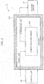
- FIG. 1 is a conceptual view of an air compression device 10 according to the first embodiment. Referring to FIG. 1 , the air compression device 10 will be described.
- the air compression device 10 includes a housing 200, a compression mechanism 300, and a cooling device 64.
- the compression mechanism 300 is arranged within the housing 200.
- the compression mechanism 300 compresses air and generates compressed air in the housing 200.
- the compression mechanism 300 may include a general scroll compressor.
- the compression mechanism 300 may include a general rotary compressor.
- the compression mechanism 300 may include a general swing compressor.
- the compression mechanism 300 may include a general reciprocating compressor. Principles of the present embodiment are not limited to any specific techniques for generating compressed air.
- compressed air is generated by a compressing operation of the compression mechanism 300, so that compressed air has a high temperature.
- the cooling device 64 is used for cooling compressed air.
- the cooling device 64 is arranged outside the housing 200. Accordingly, a designer who designs the air compression device 10 need not save a space where the cooling device 64 is to be arranged in the housing 200. Thus, a designer can give a small dimension value to the housing 200. Downsizing of the housing 200 allows reduction in amplification of vibration of the compression mechanism 300, so that vibration transmitted to a vehicle can be reduced. Also, the housing 200 has a soundproof function and a dustproof function for the compression mechanism 300.
- the cooling device 64 may be held directly by the housing 200. Alternatively, the cooling device 64 may be held by other holding members. Principles of the present embodiment are not limited to any specific configuration for holding the cooling device 64.
- Compressed air generated by the compression mechanism 300 flows into the cooling device 64 through an appropriate pipeline extending between the compression mechanism 300 and the cooling device 64.
- the compression mechanism 300 which compresses air and generates compressed air becomes high in temperature. Accordingly, a housing space covered with the housing 200 in which the compression mechanism 300 is housed is likely to be higher in temperature than an external environment provided outside the housing 200. A temperature in an external environment provided outside the housing 200 is lower than that in an internal space of the housing 200, so that the cooling device 64 installed outside the housing 200 can more efficiently cool compressed air, as compared to a case in which the cooling device 64 is installed in an internal space of the housing 200.
- the cooling device 64 may include a pipe body which meanders while circulating compressed air.
- the pipe body may be formed of a material having high thermal conductivity and be improved in terms of heat dissipation. Additionally, many heat-dissipating fins may be attached to the pipe body.
- the cooling device 64 may have any other configuration that can cool compressed air. Principles of the present embodiment are not limited to any specific configuration of the cooling device 64.
- cooling device In addition to the cooling device, other various devices may be arranged outside the housing.
- a controller arranged outside the housing, will be described.
- the controller is provided in a housing which transmits vibration thereof at a low level, a designer need not enhance a shock-proof function of internal electronic equipment.
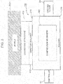
- FIG. 2 is a conceptual view of an air compression device 11 according to the second embodiment. Reference signs used in common with the first embodiment are used for elements which are conceptually common to those in the first embodiment. Referring to FIG. 2 , the air compression device 11 will be described.
- the air compression device 11 includes the housing 200, the compression mechanism 300, and the cooling device 64. Description in the first embodiment is also applied to those elements.
- the air compression device 11 further includes a controller 62.
- the controller 62 is electrically connected to the compression mechanism 300 by an appropriate signal line.
- the compression mechanism 300 compresses air and generates compressed air under control of the controller 62.
- the controller 62 is arranged outside the housing 200. Accordingly, a designer who designs the air compression device 11 need not save a space where the controller 62 is to be arranged in the housing 200. As a result, a designer can give a small dimension value to the housing 200. Downsizing of the housing 200 allows reduction in vibration transmitted to a vehicle.
- the controller 62 may be held directly by the housing 200. Alternatively, the controller 62 may be held by other holding members. Principles of the present embodiment are not limited to any specific configuration for holding the controller 62.
- a designer who designs an air compression device can design a small housing having high stiffness based on the design principles described in connection with the above-described embodiments.
- a designer may incorporate techniques for reducing vibration transmission in a connecting portion which connects a housing to a vehicle.
- techniques for reducing vibration transmission from an air compression device to a vehicle will be described.
- FIG. 3 is a conceptual view of an air compression device 100 according to the third embodiment. Reference signs used in common with the second embodiment are used for elements which are common similar to those in the second embodiment. Referring to FIG. 3 , the air compression device 100 will be described.
- the air compression device 100 is mounted to a vehicle TCH.
- vehicle TCH may be any of various apparatuses which use compressed air (a railroad vehicle, a large truck, or a mobile construction machine). Principles of the present embodiment are not limited to any specific kind of the vehicle TCH.
- a mounting position of the air compression device 100 to the vehicle TCH may be determined in conformity with a design of the vehicle TCH. If the vehicle TCH is a railroad vehicle, the air compression device 100 may be fixed to a frame of a passenger car (that is, an underside of a floor of the vehicle TCH). Principles of the present embodiment are not limited to any specific mounting position of the air compression device 100 to the vehicle TCH.
- the air compression device 100 is provided with the housing 200, the compression mechanism 300, the controller 62, and the cooling device 64. Description in the second embodiment is also applied to those elements.
- the air compression device 100 is further provided with a connecting structure 400.
- the connecting structure 400 is used for connecting the housing 200 and the vehicle TCH.
- the housing 200 includes a top plate 210 which faces an underside of a floor of the vehicle TCH.
- the top plate 210 is attached to a frame of the vehicle TCH using the connecting structure 400.
- the compression mechanism 300 is housed in the housing 200. Accordingly, the compression mechanism 300 is positioned under the top plate 210. As described in connection with the first embodiment, the compression mechanism 300 may include a scroll compressor, a rotary compressor, a swing compressor, or a reciprocating compressor.
- the compression mechanism 300 may be a combination of any of the above-stated compressors and a motor.
- a compressor and a motor may be aligned on a common horizontal plane.
- the compressor may be directly connected to the motor.
- the compressor and the motor may be vertically aligned.
- the compression mechanism 300 may include a transmission mechanism which transmits driving force from the motor to the compressor. If the compressor and the motor are vertically aligned, a designer can give a small value to an area of the housing 200 on a horizontal plane. This makes it possible to reduce a horizontal footprint of the air compression device 100 placed under a floor of the vehicle TCH. In a case where many machines should be placed under a floor of the vehicle TCH, respective spaces where machines are to be placed can be provided. Principles of the present embodiment are applicable to various configurations of the compression mechanism 300. Therefore, principles of the present embodiment are not limited to any specific configuration of the compression mechanism 300.
- Compressed air is used for operating various pneumatic equipment mounted in the vehicle TCH (pneumatic equipment used for a brake device which causes braking force to act on the vehicle TCH, or pneumatic equipment used for opening and closing a door of the vehicle TCH, for example).
- pneumatic equipment used for a brake device which causes braking force to act on the vehicle TCH or pneumatic equipment used for opening and closing a door of the vehicle TCH, for example.
- Principles of the present embodiment are not limited to any specific use of compressed air.
- the connecting structure 400 is arranged between the top plate 210 and the vehicle TCH.
- the connecting structure 400 includes a vibration isolator 410 which is in contact with the top plate 210.
- the compression mechanism 300 becomes as a source of vibration which generates vibration during generation of compressed air.
- the vibration isolator 410 reduces amplification of vibration transmitted from the compression mechanism 300 to the vehicle TCH.
- the vibration isolator 410 may include a general vibration isolating component which is formed of a material such as rubber or resin. Principles of the present embodiment are not limited to any specific component used as the vibration isolator 410.
- a designer can design various air compression devices based on the design principles described in connection with the third embodiment.
- an exemplary air compression device will be described.
- FIGs. 4A and 4B are schematic perspective views of an air compression device 100A according to the fourth embodiment. Referring to FIGs. 3 to 4B , the air compression device 100A will be described.
- the air compression device 100A includes a housing 200A and a connecting structure 400A.
- the housing 200A corresponds to the housing 200 described with reference to FIG. 3 .
- the connecting structure 400A corresponds to the connecting structure 400 described with reference to FIG. 3 .
- a compression mechanism (not shown) which generates compressed air is housed in the housing 200A.
- the housing 200A includes a top plate 210A (refer to FIG. 4A ), a substantially rectangular right panel 220 (refer to FIG. 4A ), and a substantially rectangular left panel 230 (refer to FIG. 4B ).
- the top plate 210A corresponds to the top plate 210 described with reference to FIG. 3 .
- the top plate 210A lies substantially horizontally as a whole, whereas the right panel 220 and the left panel 230 are erected substantially vertically.
- the top plate 210A includes a main plate portion 211 (refer to FIG. 4A ) and outer edge ribs 212 and 213 (refer to FIGs. 4A and 4B ).
- the main plate portion 211 forms a substantially rectangular upper surface of the housing 200A.
- the outer edge rib 212 is bent downward from the main plate portion 211, and is connected to the right panel 220.
- a bending line 214 (refer to FIG. 4A ) formed between the outer edge rib 212 and the main plate portion 211 forms one of corner lines of the housing 200A.
- the outer edge rib 213 is bent downward from the main plate portion 211, and is connected to the left panel 230.
- a bending line 215 (refer to FIG. 4B ) formed between the outer edge rib 213 and the main plate portion 211 forms another one of the corner lines of the housing 200A.
- the top plate 210A forms a front corner line 216 and a rear corner line 217.
- the front corner line 216 extends between respective front ends of the bending lines 214 and 215.
- the rear corner line 217 extends between respective rear ends (ends opposite to front ends) of the bending lines 214 and 215.
- the bending lines 214 and 215, the front corner line 216, and the rear corner line 217 form a substantially rectangular outline of an upper surface of the housing 200A.
- the connecting structure 400A includes a right connecting structure 401 and a left connecting structure 402.
- the right connecting structure 401 includes vibration isolating rubbers 411 and 412 and a frame member 420.
- the vibration isolating rubber 411 is arranged in a corner formed by the bending line 214 and the front corner line 216.
- the vibration isolating rubber 412 is arranged in a corner formed by the bending line 214 and the rear corner line 217.
- the frame member 420 has a substantially C-shaped cross section.
- the frame member 420 is arranged along the bending line 214.
- the left connecting structure 402 includes vibration isolating rubbers 413 and 414 and a frame member 430.
- the vibration isolating rubber 413 is arranged in a corner formed by the bending line 215 (refer to FIG. 4B ) and the front corner line 216.
- the vibration isolating rubber 414 is arranged in a corner formed by the bending line 215 and the rear corner line 217.
- the frame member 430 has a substantially C-shaped cross section. As shown in FIG. 4B , the frame member 430 is arranged along the bending line 215.
- the vibration isolating rubbers 411, 412, 413, and 414 may be formed of rubber which can reduce amplification of vibration.
- the vibration isolating rubbers 411, 412, 413, and 414 correspond to the vibration isolator 410 described with reference to FIG. 3 .
- the frame member 420 of the right connecting structure 401 includes a lower frame portion 421, an upper frame portion 422, and an intermediate frame portion 423.
- the vibration isolating rubbers 411 and 412 are interposed between the top plate 210A and the lower frame portion 421.
- the right connecting structure 401 is appropriately fixed to the housing 200A by a screw FXT which penetrates the top plate 210A, the vibration isolating rubbers 411 and 412, and the lower frame portion 421.
- the upper frame portion 422 is connected to a vehicle (not shown).
- the intermediate frame portion 423 holds the upper frame portion 422 in a position separated by some distance from the lower frame portion 421.
- Through holes 424 and 425 are formed in the upper frame portion 422.
- the through holes 424 and 425 are used for connecting the right connecting structure 401 and a vehicle (not shown).
- a designer may determine positions of the through holes 424 and 425 in conformity with a configuration of a vehicle.
- principles of the present embodiment are not limited to any specific positions of the through holes 424 and 425.
- a designer may form only one of the through holes 424 and 425.
- an additional through hole may be formed in the upper frame portion 422.
- Principles of the present embodiment are not limited to how many through holes are to be formed in the upper frame portion 422.
- an operator can mount the air compression device 100A to a vehicle by inserting an appropriate fixing tool such as a screw into each of the through holes 424 and 425.
- an appropriate fixing tool such as a screw
- a designer may provide an engaging structure which can engage with a vehicle, in the upper frame portion.
- Principles of the present embodiment are not limited to any specific configuration for connection between the upper frame portion and a vehicle.
- the frame member 430 of the left connecting structure 402 includes a lower frame portion 431, an upper frame portion 432, and an intermediate frame portion 433.
- the vibration isolating rubbers 413 and 414 are interposed between the top plate 210A and the lower frame portion 431.
- the left connecting structure 402 is appropriately fixed to the housing 200A by a screw (not shown) which penetrates the top plate 210A, the vibration isolating rubbers 413 and 414, and the lower frame portion 431.
- the upper frame portion 432 is connected to a vehicle (not shown).
- the intermediate frame portion 433 holds the upper frame portion 432 in a position separated by some distance from the lower frame portion 431.
- Through holes 434 and 435 are formed in the upper frame portion 432.
- the through holes 434 and 435 are used for connecting the left connecting structure 402 and a vehicle (not shown).
- a designer may determine positions of the through holes 434 and 435 in conformity with a configuration of a vehicle.
- principles of the present embodiment are not limited to any specific positions of the through holes 434 and 435.
- a designer may form only one of the through holes 434 and 435.
- an additional through hole may be formed in the upper frame portion 432.
- Principles of the present embodiment are not limited to how many through holes are to be formed in the upper frame portion 432.
- an operator can mount the air compression device 100A to a vehicle by inserting an appropriate fixing tool such as a screw into each of the through holes 434 and 435.
- an appropriate fixing tool such as a screw
- a designer may provide an engaging structure which can engage with a vehicle, in the upper frame portion.
- Principles of the present embodiment are not limited to any specific configuration for connection between the upper frame portion and a vehicle.
- a corner of a top plate is required to have high mechanical strength in order to bear a weight of an air compression device, a central portion of the top plate is not required to have such high mechanical strength as that of the corner.
- a fifth embodiment techniques for manufacturing a top plate having suitable mechanical strength will be described.
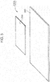
- FIG. 5 is a schematic perspective view of a plate member used in manufacture of the top plate 210A. Referring to FIGs. 4A and 5 , the top plate 210A will be described.
- the top plate 210A includes a rectangular first plate member 240 and a rectangular second plate member 250.
- the first plate member 240 is bigger than the second plate member 250.
- the second plate member 250 is arranged at an almost center of the first plate member 240 on which a cutting process and a bending process are performed, and is surrounded by the first plate member 240.
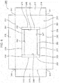
- FIG. 6 is a schematic plan view of the first plate member 240 which is provided before a bending process is performed. Referring to FIGs. 4A to 6 , processes performed on the first plate member 240 will be described.
- a solid line in FIG. 6 shows a cutting line or an outer-shape line.
- a dotted line in FIG. 6 means a bending line.
- the bending line 214 described with reference to FIG. 4A extends between the recessed corners 241 and 242.
- the outer edge rib 212 described with reference to FIG. 4A is a rectangular area which protrudes toward an outer edge of the first plate member 240 from the bending line 214.
- the bending line 215 described with reference to FIG. 4B extends between the recessed corners 243 and 244.
- the outer edge rib 213 described with reference to FIG. 4B is a rectangular area which protrudes toward an outer edge of the first plate member 240 from the bending line 215.
- the front corner line 216 described with reference to FIG. 4A extends between the recessed corners 241 and 243.
- the rear corner line 217 described with reference to FIG. 4A extends between the recessed corners 242 and 244.
- a substantially rectangular area surrounded by the bending lines 214 and 215, the front corner line 216, and the rear corner line 217 is used as a part of the main plate portion 211 (refer to FIG. 4A ) which faces an underside of a floor of a vehicle when the air compression device 100A is arranged under a floor of a vehicle (not shown).
- an example of a facing surface is shown by an upper surface of the main plate portion 211.
- the first plate member 240 includes outer edge ribs 218 and 219.
- the outer edge rib 218 is a rectangular area which protrudes toward an outer edge of the first plate member 240 from the front corner line 216.
- the outer edge rib 219 is a rectangular area which protrudes toward an outer edge of the first plate member 240 from the rear corner line 217.
- a perforation process may be performed on each of the outer edge ribs 212, 213, 218, and 219.
- An operator who assembles the air compression device 100A may compose the top plate 210A of the housing 200A by inserting an appropriate fixing tool such as a screw into a through hole formed in each of the outer edge ribs 212, 213, 218, and 219.
- Cutting lines 245 and 246 which are substantially parallel to the bending line 214 are formed within an area surrounded by the bending lines 214 and 215, the front corner line 216, and the rear corner line 217.
- the cutting line 245 is formed closer to the bending line 214 than the cutting line 246.
- Cutting lines 247 and 248 which are substantially perpendicular to the cutting line 245 are formed between the cutting lines 245 and 246.
- the cutting lines 247 and 248 extend substantially parallel to the front corner line 216.
- a plate piece in an area surrounded by the cutting lines 245, 246, 247, and 248 are removed from the first plate member 240.
- Cutting lines 261 and 262 which are perpendicular to the cutting line 245 and extend toward an outer edge of the first plate member 240 from both ends of the cutting line 245, respectively, are further formed.
- the cutting line 261 extends from a front end of the cutting line 245.
- the cutting line 262 extends from a rear end of the cutting line 245.
- a bending line 271 extending between respective distal ends of the cutting lines 261 and 262 is further formed.
- a substantially rectangular area surrounded by the cutting lines 245, 261, and 262 and the bending line 271 is used as an inner edge rib 281 which reinforces the top plate 210A.
- Cutting lines 263 and 264 which are perpendicular to the cutting line 246 and extend toward an outer edge of the first plate member 240 from both ends of the cutting line 246, respectively, are further formed.
- the cutting line 263 extends from a front end of the cutting line 246.
- the cutting line 264 extends from a rear end of the cutting line 246.
- a bending line 272 extending between respective distal ends of the cutting lines 263 and 264 is further formed.
- a substantially rectangular area surrounded by the cutting lines 246, 263, and 264 and the bending line 272 is used as an inner edge rib 282 which reinforces the top plate 210A.
- a bending line 273 extending between respective front ends of the cutting lines 245 and 246 is further formed.
- the bending line 273 is arranged in line with the cutting lines 261 and 263.
- a substantially rectangular area surrounded by the cutting lines 245, 246, and 247 and the bending line 273 is used as an inner edge rib 283.
- a bending line 274 extending between respective rear ends of the cutting lines 245 and 246 is further formed.
- the bending line 274 is arranged in line with the cutting lines 262 and 264.
- a substantially rectangular area surrounded by the cutting lines 245, 246, and 248 and the bending line 274 is used as an inner edge rib 284.
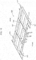
- FIG. 7 is a schematic perspective view of the first plate member 240 on which a cutting process and a bending process are performed. Referring to FIGs. 4A and 7 , the first plate member 240 will be further described.
- the first plate member 240 is bent along the bending line 214.
- the outer edge rib 212 which is bent at a substantially right angle with respect to the main plate portion 211 is formed.
- the first plate member 240 is bent along the bending line 215. As a result, the outer edge rib 213 which is bent at a substantially right angle with respect to the main plate portion 211 is formed.
- the first plate member 240 is bent along the front corner line 216.
- the outer edge rib 218 which is bent at a substantially right angle with respect to the main plate portion 211 is formed.
- the first plate member 240 is bent along the rear corner line 217.
- the outer edge rib 219 which is bent at a substantially right angle with respect to the main plate portion 211 is formed.
- the outer edge ribs 212, 213, 218, and 219 form a substantially rectangular outline of an outer shape of the top plate 210A.
- the first plate member 240 is bent along the bending line 271.
- the inner edge rib 281 which is bent at a substantially right angle with respect to the main plate portion 211 is formed.
- the first plate member 240 is bent along the bending line 272.
- the inner edge rib 282 which is bent at a substantially right angle with respect to the main plate portion 211 is formed.
- the first plate member 240 is bent along the bending line 273.
- the inner edge rib 283 which is bent at a substantially right angle with respect to the main plate portion 211 is formed.
- the first plate member 240 is bent along the bending line 274.
- the inner edge rib 284 which is bent at a substantially right angle with respect to the main plate portion 211 is formed.
- a substantially rectangular opening 280 formed by the bending lines 271, 272, 273, and 274 and the cutting lines 261, 262, 263, and 264 is formed.
- the second plate member 250 blocks the opening 280 (refer to FIG. 7 ).
- the connecting structure 400A is connected to the first plate member 240 and a vehicle, but is not connected to the second plate member 250.
- the second plate member 250 is subjected to a lighter mechanical load than that upon the first plate member 240.
- an operator who manufactures the top plate 210A can connect the second plate member 250 to the first plate member 240 with the use of such a simple connecting technique as spot welding.
- An operator may perform a bending process or a cutting process on the second plate member 250 before attaching the second plate member 250 to the opening 280. Principles of the present embodiment are not limited to any specific process performed on the second plate member 250.
- FIG. 8 is a schematic perspective view of the top plate 210A. Referring to FIGs. 4A and 8 , the top plate 210A will be described.
- the top plate 210A includes first extension ribs 291, 292, 293, and 294 and second extension ribs 295, 296, 297, and 298.
- Each of the first extension ribs 291, 292, 293, and 294 and the second extension ribs 295, 296, 297, and 298 is welded to a lower surface of the main plate portion 211 at substantially right angles.
- Each of the first extension ribs 291, 292, 293, and 294 and the second extension ribs 295, 296, 297, and 298 may be a short metal piece.
- a length of a segment for a welding process by which the first extension ribs 291, 292, 293, and 294 and the second extension ribs 295, 296, 297, and 298 are attached to the main plate portion 211 is so short that an operator can easily increase mechanical strength of the top plate 210A by welding the first extension ribs 291, 292, 293, and 294 and the second extension ribs 295, 296, 297, and 298 to the main plate portion 211.
- the first extension rib 291 extends between a right end of the inner edge rib 283 and the outer edge rib 212.
- the first extension rib 291 is arranged in line with the inner edge rib 283, and is connected to the outer edge rib 212 at substantially right angles.
- the first extension rib 292 extends between a right end of the inner edge rib 284 and the outer edge rib 212.
- the first extension rib 292 is arranged in line with the inner edge rib 284, and is connected to the outer edge rib 212 at substantially right angles.
- the first extension rib 293 extends between a left end of the inner edge rib 283 and the outer edge rib 213.
- the first extension rib 293 is arranged in line with the inner edge rib 283, and is connected to the outer edge rib 213 at substantially right angles.
- the first extension rib 294 extends between a left end of the inner edge rib 284 and the outer edge rib 213.
- the first extension rib 294 is arranged in line with the inner edge rib 284, and is connected to the outer edge rib 213 at substantially right angles.
- a set of the first extension ribs 291, 292, 293, and 294 is substantially parallel to a set of the outer edge ribs 218 and 219.
- an example of a first direction is shown by a direction in which the outer edge ribs 218 and 219 extend (in other words, a direction in which the front corner line 216 and the rear corner line 217 extend).
- An example of a first outer rib is shown by one of the outer edge ribs 218 and 219.
- An example of a first inner rib is shown by one of the inner edge ribs 283 and 284 which are substantially parallel to the set of the outer edge ribs 218 and 219.
- the second extension rib 295 extends between the first extension rib 291 and the outer edge rib 218.
- the second extension rib 295 is arranged in line with the inner edge rib 281, and is connected to the outer edge rib 218 and the first extension rib 291 at substantially right angles.
- the second extension rib 296 extends between the first extension rib 292 and the outer edge rib 219.
- the second extension rib 296 is arranged in line with the inner edge rib 281, and is connected to the outer edge rib 219 and the first extension rib 292 at substantially right angles.
- the second extension rib 297 extends between the first extension rib 293 and the outer edge rib 218.
- the second extension rib 297 is arranged in line with the inner edge rib 282, and is connected to the outer edge rib 218 and the first extension rib 293 at substantially right angles.
- the second extension rib 298 extends between the first extension rib 294 and the outer edge rib 219.
- the second extension rib 298 is arranged in line with the inner edge rib 282, and is connected to the outer edge rib 219 and the first extension rib 294 at substantially right angles.
- a set of the second extension ribs 295, 296, 297, and 298 is substantially parallel to a set of the outer edge ribs 212 and 213 which extend at substantially right angles with respect to the set of outer edge ribs 218 and 219.
- an example of a second direction is shown by a direction in which the outer edge ribs 212 and 213 extend (in other words, a direction in which the bending lines 214 and 215 extend).
- An example of a second outer rib is shown by one of the outer edge ribs 212 and 213.
- An example of a second inner rib is shown by one of the inner edge ribs 281 and 282 which are substantially parallel to the set of the outer edge ribs 212 and 213.
- the top plate 210A includes vibration isolating rubbers 251, 252, 253, and 254. Similar to the vibration isolating rubbers 411, 412, 413, and 414 described with reference to FIG. 4A , the vibration isolating rubbers 251, 252, 253, and 254 may be formed of rubber which can reduce amplification of vibration.
- the vibration isolating rubber 251 is arranged in a substantially rectangular area surrounded by the first extension rib 291, the second extension rib 295, and the outer edge ribs 212 and 218.
- a substantially rectangular area surrounded by the first extension rib 291, the second extension rib 295, and the outer edge ribs 212 and 218 is interposed between the vibration isolating rubbers 411 and 251.
- the vibration isolating rubber 252 is arranged in a substantially rectangular area surrounded by the first extension rib 292, the second extension rib 296, and the outer edge ribs 212 and 219.
- a substantially rectangular area surrounded by the first extension rib 292, the second extension rib 296, and the outer edge ribs 212 and 219 is interposed between the vibration isolating rubbers 412 and 252.
- the vibration isolating rubber 253 is arranged in a substantially rectangular area surrounded by the first extension rib 293, the second extension rib 297, and the outer edge ribs 213 and 218.
- a substantially rectangular area surrounded by the first extension rib 293, the second extension rib 297, and the outer edge ribs 213 and 218 is interposed between the vibration isolating rubbers 413 and 253.
- the vibration isolating rubber 254 is arranged in a substantially rectangular area surrounded by the first extension rib 294, the second extension rib 298, and the outer edge ribs 213 and 219.
- a substantially rectangular area surrounded by the first extension rib 294, the second extension rib 298, and the outer edge ribs 213 and 219 is interposed between the vibration isolating rubbers 414 and 254.
- Respective vibration isolating rubbers provided in four corners of the top plate 210A can damp vibration of a compression mechanism housed in the housing 200A before the vibration is transmitted to a vehicle via the housing 200A.
- a designer may design various framework structures for supporting the top plate described in connection with the fifth embodiment.
- an exemplary framework structure will be described.
- FIG. 9 is a schematic perspective view of an exemplary framework structure 500 incorporated into the housing 200A. Referring to FIGs. 8 and 9 , the framework structure 500 will be described.
- the framework structure 500 includes a bottom plate 510, an intermediate plate 520, a first column 531, a second column 532, a third column 533, a fourth column 534, an intermediate column 535, a first intermediate frame 536, and a second intermediate frame 537.
- the bottom plate 510 Similar to the top plate 210A described with reference to FIG. 8 , the bottom plate 510 has a substantially rectangular shape.
- the bottom plate 510 lies substantially horizontally under the top plate 210A.
- the intermediate plate 520 lies substantially horizontally between the top plate 210A and the bottom plate 510.
- the first column 531, the second column 532, the third column 533, and the fourth column 534 extend upward from four corners of the bottom plate 510, respectively.
- An upper end of the first column 531 is inserted into a substantially rectangular area surrounded by the first extension rib 291, the second extension rib 295, and the outer edge ribs 212 and 218 (refer to FIG. 8 ).
- An upper end of the second column 532 is inserted into a substantially rectangular area surrounded by the first extension rib 292, the second extension rib 296, and the outer edge ribs 212 and 219 (refer to FIG. 8 ).
- An upper end of the third column 533 is inserted into a substantially rectangular area surrounded by the first extension rib 293, the second extension rib 297, and the outer edge ribs 213 and 218 (refer to FIG. 8 ).
- An upper end of the fourth column 534 is inserted into a substantially rectangular area surrounded by the first extension rib 294, the second extension rib 298, and the outer edge ribs 213 and 219 (refer to FIG. 8 ).
- the first intermediate frame 536 extends substantially horizontally between the first column 531 and the third column 533.
- the first intermediate frame 536 is positioned substantially immediately under the outer edge rib 218 described with reference to FIG. 8 . Similar to the outer edge rib 218, the first intermediate frame 536 extends in a direction in which the front corner line 216 extends.
- the second intermediate frame 537 extends substantially horizontally between the second column 532 and the fourth column 534.
- the second intermediate frame 537 is positioned substantially immediately under the outer edge rib 219 forming a contour line which is an opposite side with respect to a contour line of an outer shape of the top plate 210A, the contour line being formed by the outer edge rib 218.
- the second intermediate frame 537 extends in a direction in which the rear corner line 217 extends.
- an example of a first outer rib is shown by one of the outer edge ribs 218 and 219.
- An example of a third outer rib is shown by the other of the outer edge ribs 218 and 219.
- the intermediate plate 520 is supported by the first intermediate frame 536 and the second intermediate frame 537.
- Various devices arranged within the housing 200A are mounted in the intermediate plate 520.
- the intermediate plate 520 includes a connecting plate portion 521, a left support plate 522, and a holding plate portion 523.
- the holding plate portion 523 is positioned under the connecting plate portion 521 and the left support plate 522.
- Each of the connecting plate portion 521 and the left support plate 522 is formed to be substantially T-shaped (in plan view). The connecting plate portion 521 and the left support plate 522 are held by the holding plate portion 523.
- FIG. 10 is a schematic perspective view of the holding plate portion 523. Referring to FIGs. 9 and 10 , the intermediate plate 520 will be further described.
- the holding plate portion 523 includes a lower plate 524, a frame rib 525, a lattice rib 526, and ear portions 541, 542, 543, and 544.
- the lower plate 524 lies under the connecting plate portion 521 (refer to FIG. 9 ) and the left support plate 522 (refer to FIG. 9 ).
- the frame rib 525 protrudes upward from a rectangular perimeter of the lower plate 524.
- the lattice rib 526 is erected within a rectangular space surrounded by the frame rib 525, and forms a plurality of rectangular spaces within the frame rib 525.
- the connecting plate portion 521 and the left support plate 522 are welded to upper edges of the lattice rib 526, the frame rib 525, and the ear portions 541, 542, 543, and 544.
- the ear portion 541 protrudes forward from the frame rib 525, and is joined to the first intermediate frame 536 near the first column 531.
- the ear portion 542 protrudes backward from the frame rib 525, and is joined to the second intermediate frame 537 near the second column 532.
- the ear portion 543 protrudes forward from the frame rib 525, and is joined to the first intermediate frame 536 near the third column 533.
- the ear portion 544 protrudes backward from the frame rib 525, and is joined to the second intermediate frame 537 near the fourth column 534.
- a vibration isolating piece which can reduce amplification of vibration may be arranged between each of the ear portions 541 and 543 and the first intermediate frame 536.
- a vibration isolating piece which can reduce amplification of vibration may be arranged between each of the ear portions 542 and 544 and the second intermediate frame 537.
- Principles of the present embodiment are not limited to any specific configuration for connection between each of the ear portions 541 and 543 and the first intermediate frame 536, and connection between each of the ear portions 542 and 544 and the second intermediate frame 537.
- a designer can mount various devices in the framework structure described in connection with the sixth embodiment.
- various devices mounted in the framework structure will be described.
- FIG. 11 is a schematic perspective view of the air compression device 100A. Referring to FIGs. 3 to 4B , 9 , and 11 , a configuration of an outer surface of the housing 200A will be described.
- the housing 200A includes a fixed wall 550 and a revolving wall 560.
- the fixed wall 550 blocks a substantially rectangular area which is surrounded by the first column 531 (refer to FIG. 9 ), the third column (refer to FIG. 9 ), the first intermediate frame (refer to FIG. 9 ), and the top plate 210A.
- An operator who assembles the housing 200A may use a screw in attaching the fixed wall 550 to the first column 531, the third column 533, the first intermediate frame 536, and the top plate 210A.
- the fixed wall 550 can be easily detached from the framework structure 500 (refer to FIG. 9 ).
- An operator who checks and/or repairs the air compression device 100A can detach the fixed wall 550 from the framework structure 500, and can reach various devices arranged between the top plate 210A and the intermediate plate 520.
- the revolving wall 560 is fixed under the fixed wall 550.
- the revolving wall 560 includes a substantially rectangular base frame 561, a substantially rectangular revolving frame 562, two hinges 563, three lever locks 564, and many slats 565.
- the base frame 561 is fixed to the first column 531 (refer to FIG. 9 ), the third column 533 (refer to FIG. 9 ), and the first intermediate frame 536 (refer to FIG. 9 ) by an appropriate fixing tool such as a screw.
- the two hinges 563 are attached to upper edges of the base frame 561 and the revolving frame 562.
- the revolving frame 562 can revolve upward and downward about the hinges 563.
- the three lever locks 564 join respective lower edges of the base frame 561 and the revolving frame 562.
- An operator can unlock the lever locks 564 without using a dedicated tool such as a driver or a wrench. Thereafter, an operator causes the revolving frame 562 to revolve upward, to thereby reach various devices arranged between the bottom plate 510 (refer to FIG. 9 ) and the intermediate plate 520 (refer to FIG. 9 ).
- the lever locks 564 may be commercially-available lock components. Principles of the present embodiment are not limited to any specific configuration of the lever lock 564.
- the slats 565 are fixed to the revolving frame 562. The slats 565 extend substantially horizontally within the revolving frame 562.
- the slats 565 are vertically aligned. Air outside the housing 200A can flow into the housing 200A through a space between every adjacent ones of the slats 565. Air flowing into the housing 200A may be utilized for cooling a compression mechanism (not shown).
- the air compression device 100A includes a dehumidifying device 610 and a controller 620.
- the dehumidifying device 610 blocks a substantially rectangular space surrounded by the bottom plate 510 (refer to FIG. 9 ), the second intermediate frame 537 (refer to FIG. 9 ), the fourth column 534 (refer to FIG. 9 ), and the intermediate column 535 (refer to FIG. 9 ).
- the dehumidifying device 610 dehumidifies compressed air which is generated by a compression mechanism (not shown) in the housing 200A.
- the dehumidifying device 610 may include a general dehumidifying mechanism which has a hollow-fiber membrane. Principles of the present embodiment are not limited to any specific configuration of the dehumidifying device 610.
- the controller 620 accommodates various electrical elements (not shown) and various circuits (not shown) for controlling various devices arranged in the housing 200A.
- the controller 620 blocks a substantially rectangular space surrounded by the bottom plate 510 (refer to FIG. 9 ), the second intermediate frame 537 (refer to FIG. 9 ), the second column 532 (refer to FIG. 9 ), and the intermediate column 535 (refer to FIG. 9 ).
- the controller 620 corresponds to the controller 62 described with reference to FIG. 3 .
- the housing 200A includes a duct wall 570.
- the duct wall 570 blocks a part of a substantially rectangular space surrounded by the top plate 210A, the second intermediate frame 537 (refer to FIG. 9 ), the second column 532 (refer to FIG. 9 ), and the fourth column 534 (refer to FIG. 9 ).
- the duct wall 570 includes a base plate 571 and a duct portion 572.
- the base plate 571 is fixed to the top plate 210A, the second column 532, and the fourth column 534.
- An elongated opening area 573 extending substantially horizontally is formed in the base plate 571.
- the opening area 573 is used for delivering air which is used for cooling a compression mechanism (not shown) in the housing 200A.
- the duct portion 572 surrounds the opening area 573.
- the air compression device 100A includes a guide pipe 630 which guides compressed air to an outside of the housing 200A.
- a base end of the guide pipe 630 is connected to a compression mechanism (not shown) in the housing 200A.
- the guide pipe 630 bends leftward within a substantially rectangular space surrounded by the duct portion 572, and penetrates the duct portion 572. Accordingly, a distal end of the guide pipe 630 appears outside the duct portion 572.
- the air compression device 100A includes a cooling device (aftercooler) 640 arranged outside the housing 200A.
- the cooling device 640 corresponds to the cooling device 64 described with reference to FIG. 3 .
- the cooling device 640 is arranged behind the duct wall 570.
- the cooling device 640 includes a cooling pipe 641 and a protective frame 642.
- An upstream end of the cooling pipe 641 is connected to a downstream end of the guide pipe 630.
- a downstream end of the cooling pipe 641 is connected to the dehumidifying device 610. Accordingly, compressed air can flow into the dehumidifying device 610 from the guide pipe 630 through the cooling pipe 641.
- the cooling pipe 641 extends horizontally, and guides compressed air gradually downward while meandering.
- the cooling device 640 is arranged behind the duct wall 570, so that compressed air flowing along the cooling pipe 641 is cooled by air discharged from the duct portion 572.
- the protective frame 642 surrounds an area where the cooling pipe 641 is extended. Accordingly, the cooling pipe 641 is appropriately protected from a flying foreign object (a stone, for example).
- the air compression device 100A includes an external cooling mechanism 650.
- the external cooling mechanism 650 includes four fan devices 651.
- the fan devices 651 are fixed to the base plate 571 under the duct portion 572.
- the external cooling mechanism 650 blows out air toward the cooling pipe 641 (refer to FIG. 4B ).
- compressed air flowing along the cooling pipe 641 is sufficiently cooled.
- Compressed air which is cooled flows into the dehumidifying device 610.
- Compressed air which is dehumidified by the dehumidifying device 610 may be subsequently contained in a storage tank. Compressed air in the storage tank is consumed in accordance with operations of pneumatic equipment mounted in a vehicle (not shown).
- a designer can place various devices such as a compressor and a motor in a housing.
- various devices such as a compressor and a motor in a housing.
- an exemplary internal configuration of an air compression device will be described.
- FIG. 12 is a schematic perspective view of an air compression device 100A.
- the air compression device 100A will be described with reference to FIGs. 3 , 4A , 9 , 10 , and 12 .
- the air compression device 100A includes a compression mechanism 300A and an internal cooling mechanism 660.
- the compression mechanism 300A generates compressed air.
- the internal cooling mechanism 660 cools the compression mechanism 300A.
- the compression mechanism 300A corresponds to the compression mechanism 300 described with reference to FIG. 3 .
- the compression mechanism 300A includes a compressor 310, a motor 320, and a transmission mechanism 330.
- the compressor 310 compresses air, and generates compressed air.
- the compressor 310 is arranged between the top plate 210A and the intermediate plate 520.
- the compressor 310 may be fixed directly to an upper surface of the connecting plate portion 521.
- a vibration isolating member which can reduce amplification of vibration may be arranged between the compressor 310 and the connecting plate portion 521.
- Principles of the present embodiment are not limited to any specific configuration for connection between the compressor 310 and the connecting plate portion 521. In the present embodiment, an example of a first mounting surface is shown by an upper surface of the connecting plate portion 521.
- the motor 320 is arranged between the bottom plate 510 (refer to FIG. 9 ) and the intermediate plate 520.
- the motor 320 may be fixed directly to a lower surface of the lower plate 524 described with reference to FIG. 10 .
- a vibration isolating member which can reduce amplification of vibration may be arranged between the motor 320 and the lower plate 524.
- Principles of the present embodiment are not limited to any specific configuration for connection between the motor 320 and the lower plate 524. In the present embodiment, an example of a second mounting surface is shown by a lower surface of the lower plate 524.
- a configuration of the intermediate plate 520 described in connection with the sixth embodiment allows simultaneous perforation of the connecting plate portion 521 and the lower plate 524, so that accuracy in a positional relationship between the compressor 310 and the motor 320 is extremely high in a case where both of the compressor 310 and the motor 320 are mounted in the intermediate plate 520.
- the motor 320 generates driving force for driving the compressor 310 in accordance with a control signal output from the controller 620.
- the compressor 310 and the motor 320 are vertically aligned, so that a designer can give a small value to an area of a horizontal section of the housing 200A.
- the transmission mechanism 330 transmits driving force from the motor 320 to the compressor 310.
- the right panel 220 described with reference to FIG. 4A is erected adjacently to the transmission mechanism 330, and is fixed to the framework structure 500 (refer to FIG. 9 ) by a screw.
- the right panel 220 can be easily detached from the framework structure 500, and so an operator can easily reach the transmission mechanism 330.
- the transmission mechanism 330 includes an upper pulley 331, a lower pulley 332, an endless belt 333, and a tension pulley 334.
- the upper pulley 331 is attached to the compressor 310.
- the lower pulley 332 is attached to the motor 320.
- the endless belt 333 is looped over the upper pulley 331, the lower pulley 332, and the tension pulley 334 so as to be put around those pulleys.
- the tension pulley 334 applies appropriate tensile force to the endless belt 333.
- the internal cooling mechanism 660 includes a fan device 661 and a cooling air flow adjusting box 662.
- the fixed wall 550 includes a flat plate 551 and a swelling wall 552.
- the flat plate 551 partially closes a space surrounded by the first column 531 (refer to FIG. 9 ), the third column 533 (refer to FIG. 9 ), the first intermediate frame 536 (refer to FIG. 9 ), and the top plate 210A.
- the swelling wall 552 is attached to the flat plate 551 with the use of an appropriate fixing tool such as a commercially-available lever lock or screw.
- the swelling wall 552 swells outward from the flat plate 551.
- the fan device 661 is attached to the swelling wall 552 through an opening area (not shown) formed in the flat plate 551. Accordingly, a designer need not give a large dimension value to the framework structure 500 (refer to FIG. 9 ).
- the fan device 661 may operate under control of the controller 620.
- the fan device 661 When the fan device 661 operates, air within the housing 200A is sucked by the fan device 661. During the sucking, air outside the housing 200A flows into the housing 200A through the revolving wall 560. Air flowing into the housing 200A is sucked by the fan device 661 through a clearance which is narrow and horizontally long and is formed between the intermediate plate 520 and the first intermediate frame 536. The fan device 661 delivers sucked air to the cooling air flow adjusting box 662.
- the cooling air flow adjusting box 662 is arranged between the fan device 661 and the compressor 310.
- the cooling air flow adjusting box 662 adjusts a shape of a flow region of the cooling air blown from the fan device 661.
- FIG. 13A is a schematic perspective view of the cooling air flow adjusting box 662.
- FIG. 13B is a schematic back view of the cooling air flow adjusting box 662. Referring to FIGs. 11 to 13B , the cooling air flow adjusting box 662 will be described.
- the cooling air flow adjusting box 662 includes a front plate 671, a rear plate 672, and an outer circumferential plate 673.
- the front plate 671 is arranged to face the fan device 661 (refer to FIG. 12 ).
- the front plate 671 includes an outer edge 674 and an inner edge 675.
- the outer edge 674 forms a substantially rectangular outline of the front plate 671.
- the inner edge 675 forms a substantially circular opening area.
- a diameter of the opening area formed by the inner edge 675 is substantially equal to a rotation diameter of a fan blade of the fan device 661. Otherwise, the diameter of the opening area is set to be slightly larger than a rotation diameter of a fan blade. Accordingly, cooling air generated by the fan device 661 can efficiently flow into the cooling air flow adjusting box 662.
- the rear plate 672 is erected between the front plate 671 and the compressor 310 (refer to FIG. 12 ).
- the rear plate 672 includes an outer edge 676 and an inner edge 677. Similar to the outer edge 674 of the front plate 671, the outer edge 676 of the rear plate 672 forms a substantially rectangular outline of the rear plate 672. Similar to many general compressors, the compressor 310 has a substantially rectangular outline in cross section on a virtual vertical plane including a rotation axis of the compressor 310.
- the inner edge 677 of the rear plate 672 forms a substantially rectangular opening area which is formed to be matched with the sectional shape and the sectional size of the compressor 310.
- the outer circumferential plate 673 is connected to the outer edges 674 and 676 of the front plate 671 and the rear plate 672. Accordingly, the cooling air which flows into a substantially circular opening area formed by the inner edge 675 of the front plate 671, flows out from a substantially rectangular opening area formed by the inner edge 677 of the rear plate 672, and thereby the cooling air hits the compressor 310 efficiently. Therefore, the compressor 310 is efficiently cooled.
- a cooling air generated by the fan device 661 flows toward the compressor 310 through the cooling air flow adjusting box 662.
- the cooling air collides against the compressor 310.
- the cooling air can absorb heat from the compressor 310.
- the compressor 310 is arranged between the cooling air flow adjusting box 662 and the duct wall 570. Accordingly, the cooling air generated by the fan device 661 flows toward the duct wall 570 after absorbing heat from the compressor 310. Thereafter, the cooling air is discharged from the duct portion 572 formed in the duct wall 570.
- the internal configuration described in connection with the eighth embodiment contributes to reduction in an area of a horizontal section of a housing.
- design techniques for reducing a value of a dimension along a height of a housing will be described.
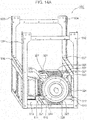
- FIGs. 14A and 14B are schematic perspective views of the framework structure 500. Referring to FIGs. 10 , 14A , and 14B , a relationship between the motor 320 and the bottom plate 510 will be described.
- the motor 320 includes a motor housing 321, two connecting brackets 322, a front fin group 323, a rear fin group 324, an upper fin group 325, and a lower fin group 326.
- a generating mechanism which generates driving force for driving the compressor 310 (that is, a mechanism which is incorporated in a general motor, such as a rotary core, a stator core, or a coil) is housed in the motor housing 321.
- Each of the front fin group 323, the rear fin group 324, the upper fin group 325, and the lower fin group 326 includes many fins.
- the front fin group 323, the rear fin group 324, the upper fin group 325, and the lower fin group 326 promote heat dissipation from the motor housing 321.
- the front fin group 323 protrudes forward from the motor housing 321.
- the rear fin group 324 protrudes backward from the motor housing 321.
- the front fin group 323 and the rear fin group 324 are positioned between the upper fin group 325 and the lower fin group 326 as for vertical positions thereof, while protruding horizontally, so that those fin groups are separated by sufficient distance from the bottom plate 510 and the intermediate plate 520 (refer to FIG. 14B ). Accordingly, the front fin group 323 and the rear fin group 324 do not interfere with the bottom plate 510 and the intermediate plate 520.
- the two connecting brackets 322 include flat upper surfaces 327, respectively.
- the upper surfaces 327 are connected to a lower surface of the lower plate 524 described with reference to FIG. 10 .
- An upper edge of each of fins of the upper fin group 325 protruding upward is positioned under the upper surfaces 327. Accordingly, the motor 320 is fixed to a lower surface of the lower plate 524 without interference between the upper fin group 325 and the lower plate 524.
- the bottom plate 510 includes a reinforcing rib 511, a second reinforcing rib 512, and a flat plate 513.
- the flat plate 513 closes a rectangular area having four corners formed of the first column 531, the second column 532, the third column 533, and the fourth column 534.
- the reinforcing rib 511 and the second reinforcing rib 512 protrude upward from the flat plate 513.
- the reinforcing rib 511 extends substantially parallel to the first intermediate frame 536.
- the second reinforcing rib 512 extends substantially perpendicularly to the reinforcing rib 511.
- the second reinforcing rib 512 is positioned to the left of the motor housing 321. Accordingly, the second reinforcing rib 512 does not interfere with the motor housing 321.
- the flat plate 513 includes a facing area 514 and a peripheral area 515.
- the facing area 514 faces the lower fin group 326 protruding downward.
- the peripheral area 515 surrounds the facing area 514.
- the reinforcing rib 511 protrudes upward in the peripheral area 515. Accordingly, the reinforcing rib 511 does not interfere with the lower fin group 326.
- the reinforcing rib 511 and the second reinforcing rib 512 are formed in positions where those ribs do not interfere with the lower fin group 326, so that a designer may give a large value to a height dimension of each of the reinforcing rib 511 and the second reinforcing rib 512. Accordingly, the bottom plate 510 can have sufficiently high mechanical strength. Even though each of the reinforcing rib 511 and the second reinforcing rib 512 has a large height dimension in order to achieve sufficiently high mechanical strength of the bottom plate 510, a designer can arrange the bottom plate 510 near the motor 320 because the reinforcing rib 511 and the second reinforcing rib 512 do not interfere with the lower fin group 326. Thus, a designer can give a small value to a height dimension of the framework structure 500.
- a designer may arrange a plurality of compressors in a housing.
- the air compression device can generate a large amount of compressed air in a short time.
- an air compression device including a plurality of compressors will be described.
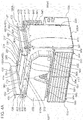
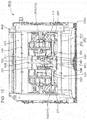
- FIG. 15 is a schematic plan view showing an internal configuration of an air compression device 100A. Referring to FIG. 15 , the air compression device 100A will be further described.
- the air compression device 100A includes a compression mechanism 340 and an internal cooling mechanism 670.
- the compression mechanism 340 generates compressed air.
- the internal cooling mechanism 670 cools the compression mechanism 340.
- the compression mechanism 340 is in a mirror-image relationship to the compression mechanism 300A described in connection with the eighth embodiment. Thus, description about the compression mechanism 300A in the eighth embodiment is also applied to the compression mechanism 340.
- the internal cooling mechanism 670 is identical to the internal cooling mechanism 660 described in connection with the eighth embodiment in terms of configuration. Accordingly, description about the internal cooling mechanism 660 in the eighth embodiment is also applied to the internal cooling mechanism 670.
- the compression mechanism 340 includes a compressor 350. Similar to the compressor 310 of the compression mechanism 300A, the compressor 350 generates compressed air.
- the compressor 310 includes a port wall 311.
- the compressor 350 includes a port wall 351.
- the port wall 311 of the compressor 310 faces the port wall 351 of the compressor 350.
- a suction port (not shown) into which air outside the housing 200A flows and a delivery port (not shown) from which compressed air is discharged are formed.
- the air compression device 100A further includes a suction guide structure 700 arranged between the port walls 311 and 351. Air outside the housing 200A flows into each of the compressors 310 and 350 through the suction guide structure 700. Each of the compressors 310 and 350 compresses outer air flown thereinto through the suction guide structure 700, to generate compressed air. Compressed air is delivered to an outside of the housing 200A through the guide pipe 630 described in connection with the seventh embodiment.
- FIG. 16 is a schematic cross-sectional view of the suction guide structure 700. Referring to FIGs. 4A , 15 , and 16 , the suction guide structure 700 will be described.
- the fixed wall 550 includes a filter cover 553.
- the filter cover 553 is arranged within a chevron-shaped recessed area formed by the swelling wall 552. Similar to the swelling wall 552, the filter cover 553 is attached to the flat plate 551. An operator can detach the filter cover 553 from the flat plate 551.
- the suction guide structure 700 includes a suction duct 710, a filter device 720, and a trim seal 731.
- the filter device 720 is arranged between the filter cover 553 and the suction duct 710.
- the trim seal 731 is a rubber ring member which connects the filter device 720 to the suction duct 710 in an airtight manner.
- the suction duct 710 is a hollow box member formed in a substantially rectangular-parallelepiped shape.
- a negative-pressure environment is generated in the suction duct 710.
- outer air outside the housing 200A flows into the housing 200A through the filter cover 553. Thereafter, the outer air passes through the filter device 720.
- the filter device 720 removes airborne dust in the outer air flowing in. The air purified by the filter device 720 flows into the suction duct 710.
- the suction guide structure 700 further includes two supply pipes 711 and 712 and two trim seals 732 and 733.
- the trim seal 732 is used for connecting the supply pipe 711 and the suction duct 710.
- the trim seal 733 is used for connecting the supply pipe 712 and the suction duct 710.
- the supply pipe 711 extends from the trim seal 732 attached to the suction duct 710, and is connected to the port wall 311 of the compressor 310.
- the outer air purified by the filter device 720 flows into the compressor 310 through the suction duct 710 and the supply pipe 711.
- the supply pipe 712 extends from the trim seal 733 attached to the suction duct 710, and is connected to the port wall 351 of the compressor 350.
- the outer air purified by the filter device 720 flows into the compressor 350 through the suction duct 710 and the supply pipe 712.
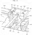
- FIG. 17 is a schematic enlarged perspective view of a part of the guide pipe 630 which guides air compressed by the compression mechanisms 300A and 340 to an outside of the housing 200A. Referring to FIGs. 15 and 17 , the guide pipe 630 will be described.
- the guide pipe 630 includes discharge pipes 631 and 632, a confluence portion 680, and a confluence pipe 633.
- the discharge pipe 631 guides compressed air generated by the compressor 310 to the confluence portion 680 arranged near the fixed wall 550.
- the discharge pipe 632 guides compressed air generated by the compressor 350 to the confluence portion 680.
- the confluence pipe 633 extends from the confluence portion 680 toward the duct wall 570 arranged opposite to the fixed wall 550, and is connected to the cooling device 640 outside the housing 200A.
- the guide pipe 630 provides a long flow path to compressed air in the housing 200A.
- the cooling air generated by the internal cooling mechanisms 660 and 670 flows within the housing 200A until the cooling air is discharged from the duct portion 572. Accordingly, compressed air can be subjected to cooling by cooling air generated by the internal cooling mechanisms 660 and 670, for a long time in the housing 200A.
- the confluence portion 680 includes a manifold 681 and two check valves 682 and 683. Each of the check valves 682 and 683 is attached to the manifold 681.
- the discharge pipe 631 is connected to the check valve 682. Compressed air which flows along the discharge pipe 631 flows into the manifold 681 through the check valve 682.
- the check valve 682 interrupts a flow of the compressed air returned from the manifold 681 to the discharge pipe 631.
- the discharge pipe 632 is connected to the check valve 683. Compressed air which flows along the discharge pipe 632 flows into the manifold 681 through the check valve 683.
- the check valve 683 interrupts a flow of the compressed air returned from the manifold 681 to the discharge pipe 632.
- a confluence inner pipe (not shown), which joins two flows of the compressed air, is formed in the manifold 681.
- the compressed air joined by the confluence inner pipe is discharged from the manifold 681 through the confluence pipe 633.
- the confluence pipe 633 is connected to the cooling device 640 (refer to FIG. 15 ).
- the air compression device 100A includes two fixing pieces 690.
- the port wall 311 includes a fixing base 312 which protrudes toward the port wall 351 of the compressor 350.
- One of the fixing pieces 690 is fixed onto the fixing base 312.
- the other fixing piece 690 for the compressor 350 similar to the fixing piece 690 for the compressor 310, is attached to a fixing base (not shown) which protrudes from the port wall 351.
- an example of a fixing member is shown by the fixing piece 690.
- each of the discharge pipes 631 and 632 bends toward the fixed wall 550 from a base end thereof which is connected to the port wall 311 or 351.
- the two fixing pieces 690 fix the discharge pipes 631 and 632, respectively, in paths from portions bending with respect to base ends toward the fixed wall 550. Accordingly, vibration caused by the compressors 310 and 350 does not apply excessively large load upon the guide pipe 630.
- the guide pipe 630 is entirely formed of a metal pipe member.
- a part of the guide pipe 630 may be formed of a pipe member having low stiffness, such as rubber or resin.
- a designer can design various air compression devices in accordance with the design principles described in connection with the above various embodiments. A part of various features described in connection with one of the above various embodiments may be applied to the air compression device described in connection with another embodiment.
- the exemplary air compression device described in connection with the above various embodiments has mainly the following features.
- the air compression device includes: a compression mechanism configured to compress air and generate compressed air; a housing in which the compression mechanism is housed; and a cooling device configured to cool the compressed air, outside the housing.
- the cooling device cools compressed air outside the housing, so that a designer who designs an air compression device need not save a space for housing a cooling device, in a housing. Accordingly, a designer can give a small dimension value to a housing. As a result, a housing can have high stiffness. Downsizing of a housing allows reduction in amplification of vibration of a compression mechanism, so that an amount of vibration transmitted to a vehicle can be kept at a low level.
- the air compression device may further include a controller configured to control the compression mechanism.
- the controller may be arranged outside the housing.
- the controller is arranged outside the housing, so that a designer who designs an air compression device need not save a space for housing a cooling device, in a housing. Accordingly, a designer can give a small dimension value to a housing. As a result, a housing can have high stiffness. Downsizing of a housing allows reduction in amplification of vibration of a compression mechanism, so that an amount of vibration transmitted to a vehicle can be kept at a low level. Also, by providing the controller in such a housing as is low in a level of vibration transmission, it is possible to eliminate a need of enhancing a shock-proof property of internal electronic equipment.
- the air compression device may further include a connecting structure configured to connect the housing to an underside of a floor of a vehicle.
- the housing may include a top plate facing the underside of the floor.
- the connecting structure may include a vibration isolator which is in contact with the top plate and is configured to reduce vibration transmission from the compression mechanism to the vehicle.
- the connecting structure includes the vibration isolator which is in contact with the top plate of the housing and is configured to reduce vibration transmission from the compression mechanism to the underside of the floor of the vehicle, so that vibration transmitted to the vehicle is reduced.
- the top plate may include a first plate member and a second plate member, the first plate member including a facing surface which faces the underside of the floor, the second plate member blocking a rectangular opening which is formed in the facing surface.
- the first plate member may include an outer edge rib and an inner edge rib, the outer edge rib being bent from the facing surface and forming a rectangular outline of the top plate, the inner edge rib being bent from the facing surface and forms a contour of the opening.
- the connecting structure may connect the first plate member to the underside of the floor.
- the first plate member of the top plate includes the outer edge rib and the inner edge rib which are bent with respect to the facing surface, so that a designer who designs an air compression device can easily form a robust structure.
- the connecting structure connects the first plate member to the vehicle. Accordingly, the air compression device is appropriately held by the vehicle.
- the outer edge rib may include a first outer rib extending in a first direction and a second outer rib extending in a second direction which is different from the first direction.
- the inner edge rib may include a first inner rib extending in the first direction and a second inner rib extending in the second direction.
- the top plate may include a first extension rib which is extended from the first inner rib in the first direction and a second extension rib which is extended from the second inner rib in the second direction.
- the vibration isolator may include a vibration isolating rubber which is arranged in a rectangular area surrounded by the first outer rib, the second outer rib, the first extension rib, and the second extension rib.
- the rectangular area where the vibration isolating rubber is arranged is surrounded by the first outer rib, the second outer rib, the first extension rib, and the second extension rib, to thereby have high stiffness. Accordingly, vibration transmitted to the vehicle is appropriately reduced.
- the outer edge rib may include a third outer rib forming a contour line which is an opposite side with respect to a contour line formed by the first outer rib.
- the housing may include a bottom plate lying under the top plate, a first intermediate frame extending in the first direction between the bottom plate and the top plate immediately under the first outer rib, a second intermediate frame extending in the first direction between the bottom plate and the top plate immediately under the third outer rib, and an intermediate plate supported by the first intermediate frame and the second intermediate frame.
- the compression mechanism may include a compressor arranged between the top plate and the intermediate plate, and a motor arranged between the bottom plate and the intermediate plate.
- the compressor is arranged between the top plate and the intermediate plate while the motor is arranged between the bottom plate and the intermediate plate, so that a designer who designs an air compression device can give a small dimension value to an area of a housing in a horizontal plane.
- a horizontal footprint of the air compression device installed under the floor of the vehicle can be reduced, which allows provision of a space where another equipment can be installed under the floor of the vehicle.
- the intermediate plate may include a holding plate portion and a connecting plate portion, the holding plate portion being joined to the first intermediate frame and the second intermediate frame, the connecting plate portion being held by the holding plate portion.
- the connecting plate portion may include a first mounting surface to which the compressor is mounted.
- the holding plate portion may include a second mounting surface opposite to the first mounting surface.
- the motor is mounted in the second mounting surface opposite to the first mounting surface, so that error factors related to relative positions of the compressor and the motor are reduced.
- the motor may include a motor housing in which a generating mechanism configured to generate driving force for driving the compressor is incorporated, and a plurality of fins protruding downward from the motor housing.
- the bottom plate may include a facing area facing the plurality of fins, a peripheral area around the facing area, and a reinforcing rib protruding upward from the peripheral area.
- the reinforcing rib protrudes upward from the peripheral area around the facing area which faces the plurality of fins, so that interference between the reinforcing rib and the plurality of fins is unlikely to occur. Accordingly, a designer can set an amount of protrusion of the reinforcing rib at a large value. As a result, stiffness of the housing is increased. In addition, a designer can set a height dimension of the housing at a small value.
Landscapes
- Engineering & Computer Science (AREA)
- Mechanical Engineering (AREA)
- General Engineering & Computer Science (AREA)
- Automation & Control Theory (AREA)
- Transportation (AREA)
- Vibration Prevention Devices (AREA)
- Compressor (AREA)
Abstract
Description
- The present invention relates to an air compression device which generates compressed air.
- An air compression device which generates compressed air is used for various uses. The compressed air generated by the air compression device mounted to a vehicle (a railroad vehicle, for example) may be supplied to a brake device which applies braking force to the vehicle or to pneumatic equipment which opens and closes a door of a vehicle in some cases.
- Patent Literature 1 proposes an air compression device mounted to a railroad vehicle. The air compression device includes a housing in which a compression mechanism which compresses air is housed. A housing by which a compression mechanism is enclosed can appropriately protect the compression mechanism from a flipped stone or other flying objects during travel of a vehicle. In addition, the housing can prevent leakage of a sound generated by a compression mechanism (sound isolating function). Further, the housing can protect a compression mechanism from dust which causes breakdown of the compression mechanism (dustproof function).
- A compression mechanism, typically, performs rotational movement, to generate compressed air. Rotational movement of the compression mechanism causes vibration, so that the compression mechanism is a source of vibration. Accordingly, if the air compression device is mounted directly in a vehicle, vibration is easily transmitted to a vehicle through a housing in which the compression mechanism is housed. More specifically, vibration of the compression mechanism is transmitted to a housing supporting the compression mechanism, and then is transmitted to a frame of a vehicle connected with the housing. Vibration transmission to a vehicle gives unpleasantness to a passenger in a vehicle. That is, riding comfort is degraded.
- Patent Literature 1: Japanese Utility Model Registration Publication No.
3150077 - It is an object of the present invention to provide an air compression device which allows reduction of vibration transmitted to a vehicle.
- An air compression device according to one aspect of the present invention includes: a compression mechanism configured to compress air and generate compressed air; a housing in which the compression mechanism is housed; and a cooling device configured to cool the compressed air, outside the housing.
- In the above-described air compression device, because of provision of the cooling device outside the housing, there is no need to save a space where the cooling device is to be arranged in the housing, so that the housing can be designed to be smaller. Downsizing of the housing allows reduction in amplification of vibration of the compression mechanism, which results in reduction in vibration transmitted to a vehicle.
- The objects, features, and advantages of the present invention will become more apparent from the following detailed description of the present invention when taken in conjunction with the accompanying drawings.
-
-
FIG. 1 is a schematic view of an air compression device according to a first embodiment. -
FIG. 2 is a schematic view of an air compression device according to a second embodiment. -
FIG. 3 is a schematic view of an air compression device according to a third embodiment -
FIG. 4A is a schematic perspective view of an air compression device according to a fourth embodiment. -
FIG. 4B is another schematic perspective view of the air compression device shown inFIG. 4A . -
FIG. 5 is a schematic perspective view of a plate member used in manufacture of a top plate of the air compression device shown inFIG. 4A (a fifth embodiment). -
FIG. 6 is a schematic plan view of a first plate member of the air compression device shown inFIG. 4A . -
FIG. 7 is a schematic perspective view of the first plate member shown inFIG. 6 . -
FIG. 8 is a schematic perspective view of the top plate of the air compression device shown inFIG. 4A . -
FIG. 9 is a schematic perspective view of an exemplary framework structure incorporated in a housing of the air compression device shown inFIG. 4A (a sixth embodiment). -
FIG. 10 is a schematic perspective view of a holding plate portion of the framework structure shown inFIG. 9 . -
FIG. 11 is another schematic perspective view of the air compression device shown inFIG. 4A (a seventh embodiment). -
FIG. 12 is another schematic perspective view of the air compression device shown inFIG. 4A (an eighth embodiment). -
FIG. 13A is a schematic perspective view of a cooling air flow adjusting box of the air compression device shown inFIG. 12 . -
FIG. 13B is a schematic back view of the cooling air flow adjusting box shown inFIG. 13A . -
FIG. 14A is another schematic perspective view of the framework structure shown inFIG. 9 (a ninth embodiment). -
FIG. 14B is another schematic perspective view of the framework structure shown inFIG. 14A (the ninth embodiment). -
FIG. 15 is a schematic plan view showing an internal configuration of the air compression device shown inFIG. 4A (a tenth embodiment). -
FIG. 16 is a schematic cross-sectional view of a suction guide structure of the air compression device shown inFIG. 15 . -
FIG. 17 is a schematic enlarged perspective view of a part of a guide pipe for guide in the air compression device shown inFIG. 15 . - The present inventors have found that a small housing tends to have high stiffness. In addition, the present inventors have found that when a compression mechanism which is a source of vibration is arranged in a housing, downsizing of the housing could reduce amplification of vibration of the compression mechanism, so that vibration transmitted to a vehicle could be kept at a low level. In a first embodiment, an exemplary air compression device which is constructed based on those findings will be described.
-
FIG. 1 is a conceptual view of anair compression device 10 according to the first embodiment. Referring toFIG. 1 , theair compression device 10 will be described. - The
air compression device 10 includes ahousing 200, acompression mechanism 300, and acooling device 64. Thecompression mechanism 300 is arranged within thehousing 200. Thecompression mechanism 300 compresses air and generates compressed air in thehousing 200. Thecompression mechanism 300 may include a general scroll compressor. Alternatively, thecompression mechanism 300 may include a general rotary compressor. Further alternatively, thecompression mechanism 300 may include a general swing compressor. Further alternatively, thecompression mechanism 300 may include a general reciprocating compressor. Principles of the present embodiment are not limited to any specific techniques for generating compressed air. - As described above, compressed air is generated by a compressing operation of the
compression mechanism 300, so that compressed air has a high temperature. Thecooling device 64 is used for cooling compressed air. - The
cooling device 64 is arranged outside thehousing 200. Accordingly, a designer who designs theair compression device 10 need not save a space where thecooling device 64 is to be arranged in thehousing 200. Thus, a designer can give a small dimension value to thehousing 200. Downsizing of thehousing 200 allows reduction in amplification of vibration of thecompression mechanism 300, so that vibration transmitted to a vehicle can be reduced. Also, thehousing 200 has a soundproof function and a dustproof function for thecompression mechanism 300. Thecooling device 64 may be held directly by thehousing 200. Alternatively, thecooling device 64 may be held by other holding members. Principles of the present embodiment are not limited to any specific configuration for holding thecooling device 64. - Compressed air generated by the
compression mechanism 300 flows into thecooling device 64 through an appropriate pipeline extending between thecompression mechanism 300 and thecooling device 64. Thecompression mechanism 300 which compresses air and generates compressed air becomes high in temperature. Accordingly, a housing space covered with thehousing 200 in which thecompression mechanism 300 is housed is likely to be higher in temperature than an external environment provided outside thehousing 200. A temperature in an external environment provided outside thehousing 200 is lower than that in an internal space of thehousing 200, so that thecooling device 64 installed outside thehousing 200 can more efficiently cool compressed air, as compared to a case in which thecooling device 64 is installed in an internal space of thehousing 200. - The
cooling device 64 may include a pipe body which meanders while circulating compressed air. In order to more efficiently cool compressed air, the pipe body may be formed of a material having high thermal conductivity and be improved in terms of heat dissipation. Additionally, many heat-dissipating fins may be attached to the pipe body. Alternatively, thecooling device 64 may have any other configuration that can cool compressed air. Principles of the present embodiment are not limited to any specific configuration of thecooling device 64. - In addition to the cooling device, other various devices may be arranged outside the housing. In a second embodiment, an exemplary air compression device which includes a controller arranged outside the housing, will be described. In a case where the controller is provided in a housing which transmits vibration thereof at a low level, a designer need not enhance a shock-proof function of internal electronic equipment.
-
FIG. 2 is a conceptual view of an air compression device 11 according to the second embodiment. Reference signs used in common with the first embodiment are used for elements which are conceptually common to those in the first embodiment. Referring toFIG. 2 , the air compression device 11 will be described. - In the same manner as in the first embodiment, the air compression device 11 includes the
housing 200, thecompression mechanism 300, and thecooling device 64. Description in the first embodiment is also applied to those elements. - The air compression device 11 further includes a
controller 62. Thecontroller 62 is electrically connected to thecompression mechanism 300 by an appropriate signal line. Thecompression mechanism 300 compresses air and generates compressed air under control of thecontroller 62. - The
controller 62 is arranged outside thehousing 200. Accordingly, a designer who designs the air compression device 11 need not save a space where thecontroller 62 is to be arranged in thehousing 200. As a result, a designer can give a small dimension value to thehousing 200. Downsizing of thehousing 200 allows reduction in vibration transmitted to a vehicle. Thecontroller 62 may be held directly by thehousing 200. Alternatively, thecontroller 62 may be held by other holding members. Principles of the present embodiment are not limited to any specific configuration for holding thecontroller 62. - A designer who designs an air compression device can design a small housing having high stiffness based on the design principles described in connection with the above-described embodiments. A designer may incorporate techniques for reducing vibration transmission in a connecting portion which connects a housing to a vehicle. In a third embodiment, techniques for reducing vibration transmission from an air compression device to a vehicle will be described.
-
FIG. 3 is a conceptual view of anair compression device 100 according to the third embodiment. Reference signs used in common with the second embodiment are used for elements which are common similar to those in the second embodiment. Referring toFIG. 3 , theair compression device 100 will be described. - The
air compression device 100 is mounted to a vehicle TCH. The vehicle TCH may be any of various apparatuses which use compressed air (a railroad vehicle, a large truck, or a mobile construction machine). Principles of the present embodiment are not limited to any specific kind of the vehicle TCH. - A mounting position of the
air compression device 100 to the vehicle TCH may be determined in conformity with a design of the vehicle TCH. If the vehicle TCH is a railroad vehicle, theair compression device 100 may be fixed to a frame of a passenger car (that is, an underside of a floor of the vehicle TCH). Principles of the present embodiment are not limited to any specific mounting position of theair compression device 100 to the vehicle TCH. - In the same manner as in the second embodiment, the
air compression device 100 is provided with thehousing 200, thecompression mechanism 300, thecontroller 62, and thecooling device 64. Description in the second embodiment is also applied to those elements. - The
air compression device 100 is further provided with a connectingstructure 400. The connectingstructure 400 is used for connecting thehousing 200 and the vehicle TCH. Thehousing 200 includes atop plate 210 which faces an underside of a floor of the vehicle TCH. Thetop plate 210 is attached to a frame of the vehicle TCH using the connectingstructure 400. - The
compression mechanism 300 is housed in thehousing 200. Accordingly, thecompression mechanism 300 is positioned under thetop plate 210. As described in connection with the first embodiment, thecompression mechanism 300 may include a scroll compressor, a rotary compressor, a swing compressor, or a reciprocating compressor. - The
compression mechanism 300 may be a combination of any of the above-stated compressors and a motor. A compressor and a motor may be aligned on a common horizontal plane. In this case, the compressor may be directly connected to the motor. Alternatively, the compressor and the motor may be vertically aligned. In this case, thecompression mechanism 300 may include a transmission mechanism which transmits driving force from the motor to the compressor. If the compressor and the motor are vertically aligned, a designer can give a small value to an area of thehousing 200 on a horizontal plane. This makes it possible to reduce a horizontal footprint of theair compression device 100 placed under a floor of the vehicle TCH. In a case where many machines should be placed under a floor of the vehicle TCH, respective spaces where machines are to be placed can be provided. Principles of the present embodiment are applicable to various configurations of thecompression mechanism 300. Therefore, principles of the present embodiment are not limited to any specific configuration of thecompression mechanism 300. - Compressed air is used for operating various pneumatic equipment mounted in the vehicle TCH (pneumatic equipment used for a brake device which causes braking force to act on the vehicle TCH, or pneumatic equipment used for opening and closing a door of the vehicle TCH, for example). Principles of the present embodiment are not limited to any specific use of compressed air.
- The connecting
structure 400 is arranged between thetop plate 210 and the vehicle TCH. The connectingstructure 400 includes avibration isolator 410 which is in contact with thetop plate 210. Thecompression mechanism 300 becomes as a source of vibration which generates vibration during generation of compressed air. Thevibration isolator 410 reduces amplification of vibration transmitted from thecompression mechanism 300 to the vehicle TCH. Thevibration isolator 410 may include a general vibration isolating component which is formed of a material such as rubber or resin. Principles of the present embodiment are not limited to any specific component used as thevibration isolator 410. - A designer can design various air compression devices based on the design principles described in connection with the third embodiment. In a fourth embodiment, an exemplary air compression device will be described.
-
FIGs. 4A and4B are schematic perspective views of anair compression device 100A according to the fourth embodiment. Referring toFIGs. 3 to 4B , theair compression device 100A will be described. - The
air compression device 100A includes ahousing 200A and a connectingstructure 400A. Thehousing 200A corresponds to thehousing 200 described with reference toFIG. 3 . The connectingstructure 400A corresponds to the connectingstructure 400 described with reference toFIG. 3 . A compression mechanism (not shown) which generates compressed air is housed in thehousing 200A. - The
housing 200A includes atop plate 210A (refer toFIG. 4A ), a substantially rectangular right panel 220 (refer toFIG. 4A ), and a substantially rectangular left panel 230 (refer toFIG. 4B ). Thetop plate 210A corresponds to thetop plate 210 described with reference toFIG. 3 . Thetop plate 210A lies substantially horizontally as a whole, whereas theright panel 220 and theleft panel 230 are erected substantially vertically. - The
top plate 210A includes a main plate portion 211 (refer toFIG. 4A ) andouter edge ribs 212 and 213 (refer toFIGs. 4A and4B ). Themain plate portion 211 forms a substantially rectangular upper surface of thehousing 200A. Theouter edge rib 212 is bent downward from themain plate portion 211, and is connected to theright panel 220. A bending line 214 (refer toFIG. 4A ) formed between theouter edge rib 212 and themain plate portion 211 forms one of corner lines of thehousing 200A. Theouter edge rib 213 is bent downward from themain plate portion 211, and is connected to theleft panel 230. A bending line 215 (refer toFIG. 4B ) formed between theouter edge rib 213 and themain plate portion 211 forms another one of the corner lines of thehousing 200A. - As shown in
FIG. 4A , thetop plate 210A forms afront corner line 216 and arear corner line 217. Thefront corner line 216 extends between respective front ends of thebending lines rear corner line 217 extends between respective rear ends (ends opposite to front ends) of thebending lines front corner line 216, and therear corner line 217 form a substantially rectangular outline of an upper surface of thehousing 200A. - The connecting
structure 400A includes aright connecting structure 401 and aleft connecting structure 402. As shown inFIG. 4A , theright connecting structure 401 includesvibration isolating rubbers frame member 420. Thevibration isolating rubber 411 is arranged in a corner formed by thebending line 214 and thefront corner line 216. Thevibration isolating rubber 412 is arranged in a corner formed by thebending line 214 and therear corner line 217. Theframe member 420 has a substantially C-shaped cross section. Theframe member 420 is arranged along thebending line 214. Theleft connecting structure 402 includesvibration isolating rubbers frame member 430. Thevibration isolating rubber 413 is arranged in a corner formed by the bending line 215 (refer toFIG. 4B ) and thefront corner line 216. Thevibration isolating rubber 414 is arranged in a corner formed by thebending line 215 and therear corner line 217. Theframe member 430 has a substantially C-shaped cross section. As shown inFIG. 4B , theframe member 430 is arranged along thebending line 215. - The
vibration isolating rubbers vibration isolating rubbers vibration isolator 410 described with reference toFIG. 3 . - As shown in
FIG. 4A , theframe member 420 of theright connecting structure 401 includes alower frame portion 421, anupper frame portion 422, and anintermediate frame portion 423. Thevibration isolating rubbers top plate 210A and thelower frame portion 421. Theright connecting structure 401 is appropriately fixed to thehousing 200A by a screw FXT which penetrates thetop plate 210A, thevibration isolating rubbers lower frame portion 421. Theupper frame portion 422 is connected to a vehicle (not shown). Theintermediate frame portion 423 holds theupper frame portion 422 in a position separated by some distance from thelower frame portion 421. - Through
holes upper frame portion 422. The throughholes right connecting structure 401 and a vehicle (not shown). A designer may determine positions of the throughholes holes - A designer may form only one of the through
holes upper frame portion 422. Principles of the present embodiment are not limited to how many through holes are to be formed in theupper frame portion 422. - According to the present embodiment, an operator can mount the
air compression device 100A to a vehicle by inserting an appropriate fixing tool such as a screw into each of the throughholes - As shown in
FIG. 4A , theframe member 430 of theleft connecting structure 402 includes alower frame portion 431, anupper frame portion 432, and anintermediate frame portion 433. Thevibration isolating rubbers top plate 210A and thelower frame portion 431. Theleft connecting structure 402 is appropriately fixed to thehousing 200A by a screw (not shown) which penetrates thetop plate 210A, thevibration isolating rubbers lower frame portion 431. Theupper frame portion 432 is connected to a vehicle (not shown). Theintermediate frame portion 433 holds theupper frame portion 432 in a position separated by some distance from thelower frame portion 431. - Through
holes upper frame portion 432. The throughholes left connecting structure 402 and a vehicle (not shown). A designer may determine positions of the throughholes holes - A designer may form only one of the through
holes upper frame portion 432. Principles of the present embodiment are not limited to how many through holes are to be formed in theupper frame portion 432. - According to the present embodiment, an operator can mount the
air compression device 100A to a vehicle by inserting an appropriate fixing tool such as a screw into each of the throughholes - In a case where the design principles of the air compression device described in connection with the fourth embodiment are employed, while a corner of a top plate is required to have high mechanical strength in order to bear a weight of an air compression device, a central portion of the top plate is not required to have such high mechanical strength as that of the corner. According to a fifth embodiment, techniques for manufacturing a top plate having suitable mechanical strength will be described.
-
FIG. 5 is a schematic perspective view of a plate member used in manufacture of thetop plate 210A. Referring toFIGs. 4A and5 , thetop plate 210A will be described. - As shown in
FIG. 5 , thetop plate 210A includes a rectangularfirst plate member 240 and a rectangularsecond plate member 250. Thefirst plate member 240 is bigger than thesecond plate member 250. As shown inFIG. 4A , thesecond plate member 250 is arranged at an almost center of thefirst plate member 240 on which a cutting process and a bending process are performed, and is surrounded by thefirst plate member 240. -
FIG. 6 is a schematic plan view of thefirst plate member 240 which is provided before a bending process is performed. Referring toFIGs. 4A to 6 , processes performed on thefirst plate member 240 will be described. - A solid line in
FIG. 6 shows a cutting line or an outer-shape line. A dotted line inFIG. 6 means a bending line. - Four corners of the
first plate member 240 in a rectangular shape shown inFIG. 5 are cut, so that four recessedcorners bending line 214 described with reference toFIG. 4A extends between the recessedcorners outer edge rib 212 described with reference toFIG. 4A is a rectangular area which protrudes toward an outer edge of thefirst plate member 240 from thebending line 214. Thebending line 215 described with reference toFIG. 4B extends between the recessedcorners outer edge rib 213 described with reference toFIG. 4B is a rectangular area which protrudes toward an outer edge of thefirst plate member 240 from thebending line 215. - The
front corner line 216 described with reference toFIG. 4A extends between the recessedcorners rear corner line 217 described with reference toFIG. 4A extends between the recessedcorners lines front corner line 216, and therear corner line 217 is used as a part of the main plate portion 211 (refer toFIG. 4A ) which faces an underside of a floor of a vehicle when theair compression device 100A is arranged under a floor of a vehicle (not shown). In the present embodiment, an example of a facing surface is shown by an upper surface of themain plate portion 211. - As shown in
FIG. 6 , thefirst plate member 240 includesouter edge ribs outer edge rib 218 is a rectangular area which protrudes toward an outer edge of thefirst plate member 240 from thefront corner line 216. Theouter edge rib 219 is a rectangular area which protrudes toward an outer edge of thefirst plate member 240 from therear corner line 217. A perforation process may be performed on each of theouter edge ribs air compression device 100A may compose thetop plate 210A of thehousing 200A by inserting an appropriate fixing tool such as a screw into a through hole formed in each of theouter edge ribs - Cutting
lines bending line 214 are formed within an area surrounded by the bendinglines front corner line 216, and therear corner line 217. Thecutting line 245 is formed closer to thebending line 214 than thecutting line 246. - Cutting
lines cutting line 245 are formed between the cuttinglines front corner line 216. A plate piece in an area surrounded by the cuttinglines first plate member 240. - Cutting
lines cutting line 245 and extend toward an outer edge of thefirst plate member 240 from both ends of thecutting line 245, respectively, are further formed. Thecutting line 261 extends from a front end of thecutting line 245. Thecutting line 262 extends from a rear end of thecutting line 245. - A
bending line 271 extending between respective distal ends of thecutting lines lines bending line 271 is used as aninner edge rib 281 which reinforces thetop plate 210A. - Cutting
lines cutting line 246 and extend toward an outer edge of thefirst plate member 240 from both ends of thecutting line 246, respectively, are further formed. Thecutting line 263 extends from a front end of thecutting line 246. Thecutting line 264 extends from a rear end of thecutting line 246. - A
bending line 272 extending between respective distal ends of thecutting lines lines bending line 272 is used as aninner edge rib 282 which reinforces thetop plate 210A. - A
bending line 273 extending between respective front ends of thecutting lines bending line 273 is arranged in line with the cuttinglines lines bending line 273 is used as aninner edge rib 283. - A
bending line 274 extending between respective rear ends of thecutting lines bending line 274 is arranged in line with the cuttinglines lines bending line 274 is used as aninner edge rib 284. -
FIG. 7 is a schematic perspective view of thefirst plate member 240 on which a cutting process and a bending process are performed. Referring toFIGs. 4A and7 , thefirst plate member 240 will be further described. - As shown in
FIG. 7 , thefirst plate member 240 is bent along thebending line 214. As a result, theouter edge rib 212 which is bent at a substantially right angle with respect to themain plate portion 211 is formed. - The
first plate member 240 is bent along thebending line 215. As a result, theouter edge rib 213 which is bent at a substantially right angle with respect to themain plate portion 211 is formed. - The
first plate member 240 is bent along thefront corner line 216. As a result, theouter edge rib 218 which is bent at a substantially right angle with respect to themain plate portion 211 is formed. - The
first plate member 240 is bent along therear corner line 217. As a result, theouter edge rib 219 which is bent at a substantially right angle with respect to themain plate portion 211 is formed. - The
outer edge ribs top plate 210A. - The
first plate member 240 is bent along thebending line 271. As a result, theinner edge rib 281 which is bent at a substantially right angle with respect to themain plate portion 211 is formed. - The
first plate member 240 is bent along thebending line 272. As a result, theinner edge rib 282 which is bent at a substantially right angle with respect to themain plate portion 211 is formed. - The
first plate member 240 is bent along thebending line 273. As a result, theinner edge rib 283 which is bent at a substantially right angle with respect to themain plate portion 211 is formed. - The
first plate member 240 is bent along thebending line 274. As a result, theinner edge rib 284 which is bent at a substantially right angle with respect to themain plate portion 211 is formed. - As a result of a bending process for forming the
inner edge ribs rectangular opening 280 formed by the bendinglines cutting lines - As shown in
FIG. 4A , thesecond plate member 250 blocks the opening 280 (refer toFIG. 7 ). The connectingstructure 400A is connected to thefirst plate member 240 and a vehicle, but is not connected to thesecond plate member 250. As a result, thesecond plate member 250 is subjected to a lighter mechanical load than that upon thefirst plate member 240. Accordingly, an operator who manufactures thetop plate 210A can connect thesecond plate member 250 to thefirst plate member 240 with the use of such a simple connecting technique as spot welding. An operator may perform a bending process or a cutting process on thesecond plate member 250 before attaching thesecond plate member 250 to theopening 280. Principles of the present embodiment are not limited to any specific process performed on thesecond plate member 250. -
FIG. 8 is a schematic perspective view of thetop plate 210A. Referring toFIGs. 4A and8 , thetop plate 210A will be described. - As shown in
FIG. 8 , thetop plate 210A includesfirst extension ribs second extension ribs first extension ribs second extension ribs main plate portion 211 at substantially right angles. Each of thefirst extension ribs second extension ribs first extension ribs second extension ribs main plate portion 211 is so short that an operator can easily increase mechanical strength of thetop plate 210A by welding thefirst extension ribs second extension ribs main plate portion 211. - The
first extension rib 291 extends between a right end of theinner edge rib 283 and theouter edge rib 212. Thefirst extension rib 291 is arranged in line with theinner edge rib 283, and is connected to theouter edge rib 212 at substantially right angles. Thefirst extension rib 292 extends between a right end of theinner edge rib 284 and theouter edge rib 212. Thefirst extension rib 292 is arranged in line with theinner edge rib 284, and is connected to theouter edge rib 212 at substantially right angles. Thefirst extension rib 293 extends between a left end of theinner edge rib 283 and theouter edge rib 213. Thefirst extension rib 293 is arranged in line with theinner edge rib 283, and is connected to theouter edge rib 213 at substantially right angles. Thefirst extension rib 294 extends between a left end of theinner edge rib 284 and theouter edge rib 213. Thefirst extension rib 294 is arranged in line with theinner edge rib 284, and is connected to theouter edge rib 213 at substantially right angles. A set of thefirst extension ribs outer edge ribs outer edge ribs front corner line 216 and therear corner line 217 extend). An example of a first outer rib is shown by one of theouter edge ribs inner edge ribs outer edge ribs - The
second extension rib 295 extends between thefirst extension rib 291 and theouter edge rib 218. Thesecond extension rib 295 is arranged in line with theinner edge rib 281, and is connected to theouter edge rib 218 and thefirst extension rib 291 at substantially right angles. Thesecond extension rib 296 extends between thefirst extension rib 292 and theouter edge rib 219. Thesecond extension rib 296 is arranged in line with theinner edge rib 281, and is connected to theouter edge rib 219 and thefirst extension rib 292 at substantially right angles. Thesecond extension rib 297 extends between thefirst extension rib 293 and theouter edge rib 218. Thesecond extension rib 297 is arranged in line with theinner edge rib 282, and is connected to theouter edge rib 218 and thefirst extension rib 293 at substantially right angles. Thesecond extension rib 298 extends between thefirst extension rib 294 and theouter edge rib 219. Thesecond extension rib 298 is arranged in line with theinner edge rib 282, and is connected to theouter edge rib 219 and thefirst extension rib 294 at substantially right angles. A set of thesecond extension ribs outer edge ribs outer edge ribs outer edge ribs bending lines outer edge ribs inner edge ribs outer edge ribs - The
top plate 210A includesvibration isolating rubbers vibration isolating rubbers FIG. 4A , thevibration isolating rubbers - The
vibration isolating rubber 251 is arranged in a substantially rectangular area surrounded by thefirst extension rib 291, thesecond extension rib 295, and theouter edge ribs main plate portion 211, a substantially rectangular area surrounded by thefirst extension rib 291, thesecond extension rib 295, and theouter edge ribs vibration isolating rubbers vibration isolating rubber 252 is arranged in a substantially rectangular area surrounded by thefirst extension rib 292, thesecond extension rib 296, and theouter edge ribs main plate portion 211, a substantially rectangular area surrounded by thefirst extension rib 292, thesecond extension rib 296, and theouter edge ribs vibration isolating rubbers vibration isolating rubber 253 is arranged in a substantially rectangular area surrounded by thefirst extension rib 293, thesecond extension rib 297, and theouter edge ribs main plate portion 211, a substantially rectangular area surrounded by thefirst extension rib 293, thesecond extension rib 297, and theouter edge ribs vibration isolating rubbers vibration isolating rubber 254 is arranged in a substantially rectangular area surrounded by thefirst extension rib 294, thesecond extension rib 298, and theouter edge ribs main plate portion 211, a substantially rectangular area surrounded by thefirst extension rib 294, thesecond extension rib 298, and theouter edge ribs vibration isolating rubbers top plate 210A can damp vibration of a compression mechanism housed in thehousing 200A before the vibration is transmitted to a vehicle via thehousing 200A. - A designer may design various framework structures for supporting the top plate described in connection with the fifth embodiment. In a sixth embodiment, an exemplary framework structure will be described.
-
FIG. 9 is a schematic perspective view of anexemplary framework structure 500 incorporated into thehousing 200A. Referring toFIGs. 8 and9 , theframework structure 500 will be described. - The
framework structure 500 includes abottom plate 510, anintermediate plate 520, afirst column 531, asecond column 532, athird column 533, afourth column 534, anintermediate column 535, a firstintermediate frame 536, and a secondintermediate frame 537. Similar to thetop plate 210A described with reference toFIG. 8 , thebottom plate 510 has a substantially rectangular shape. Thebottom plate 510 lies substantially horizontally under thetop plate 210A. Theintermediate plate 520 lies substantially horizontally between thetop plate 210A and thebottom plate 510. - The
first column 531, thesecond column 532, thethird column 533, and thefourth column 534 extend upward from four corners of thebottom plate 510, respectively. An upper end of thefirst column 531 is inserted into a substantially rectangular area surrounded by thefirst extension rib 291, thesecond extension rib 295, and theouter edge ribs 212 and 218 (refer toFIG. 8 ). An upper end of thesecond column 532 is inserted into a substantially rectangular area surrounded by thefirst extension rib 292, thesecond extension rib 296, and theouter edge ribs 212 and 219 (refer toFIG. 8 ). An upper end of thethird column 533 is inserted into a substantially rectangular area surrounded by thefirst extension rib 293, thesecond extension rib 297, and theouter edge ribs 213 and 218 (refer toFIG. 8 ). An upper end of thefourth column 534 is inserted into a substantially rectangular area surrounded by thefirst extension rib 294, thesecond extension rib 298, and theouter edge ribs 213 and 219 (refer toFIG. 8 ). - The first
intermediate frame 536 extends substantially horizontally between thefirst column 531 and thethird column 533. The firstintermediate frame 536 is positioned substantially immediately under theouter edge rib 218 described with reference toFIG. 8 . Similar to theouter edge rib 218, the firstintermediate frame 536 extends in a direction in which thefront corner line 216 extends. The secondintermediate frame 537 extends substantially horizontally between thesecond column 532 and thefourth column 534. The secondintermediate frame 537 is positioned substantially immediately under theouter edge rib 219 forming a contour line which is an opposite side with respect to a contour line of an outer shape of thetop plate 210A, the contour line being formed by theouter edge rib 218. Similar to theouter edge rib 219, the secondintermediate frame 537 extends in a direction in which therear corner line 217 extends. In the present embodiment, an example of a first outer rib is shown by one of theouter edge ribs outer edge ribs - The
intermediate plate 520 is supported by the firstintermediate frame 536 and the secondintermediate frame 537. Various devices arranged within thehousing 200A are mounted in theintermediate plate 520. - The
intermediate plate 520 includes a connectingplate portion 521, aleft support plate 522, and a holdingplate portion 523. The holdingplate portion 523 is positioned under the connectingplate portion 521 and theleft support plate 522. Each of the connectingplate portion 521 and theleft support plate 522 is formed to be substantially T-shaped (in plan view). The connectingplate portion 521 and theleft support plate 522 are held by the holdingplate portion 523. -
FIG. 10 is a schematic perspective view of the holdingplate portion 523. Referring toFIGs. 9 and10 , theintermediate plate 520 will be further described. - The holding
plate portion 523 includes alower plate 524, aframe rib 525, alattice rib 526, andear portions lower plate 524 lies under the connecting plate portion 521 (refer toFIG. 9 ) and the left support plate 522 (refer toFIG. 9 ). Theframe rib 525 protrudes upward from a rectangular perimeter of thelower plate 524. Thelattice rib 526 is erected within a rectangular space surrounded by theframe rib 525, and forms a plurality of rectangular spaces within theframe rib 525. The connectingplate portion 521 and theleft support plate 522 are welded to upper edges of thelattice rib 526, theframe rib 525, and theear portions - As shown in
FIG. 9 , theear portion 541 protrudes forward from theframe rib 525, and is joined to the firstintermediate frame 536 near thefirst column 531. Theear portion 542 protrudes backward from theframe rib 525, and is joined to the secondintermediate frame 537 near thesecond column 532. Theear portion 543 protrudes forward from theframe rib 525, and is joined to the firstintermediate frame 536 near thethird column 533. Theear portion 544 protrudes backward from theframe rib 525, and is joined to the secondintermediate frame 537 near thefourth column 534. - A vibration isolating piece which can reduce amplification of vibration may be arranged between each of the
ear portions intermediate frame 536. A vibration isolating piece which can reduce amplification of vibration may be arranged between each of theear portions intermediate frame 537. Principles of the present embodiment are not limited to any specific configuration for connection between each of theear portions intermediate frame 536, and connection between each of theear portions intermediate frame 537. - A designer can mount various devices in the framework structure described in connection with the sixth embodiment. In a seventh embodiment, various devices mounted in the framework structure will be described.
-
FIG. 11 is a schematic perspective view of theair compression device 100A. Referring toFIGs. 3 to 4B ,9 , and11 , a configuration of an outer surface of thehousing 200A will be described. - As shown in
FIG. 4A , thehousing 200A includes a fixedwall 550 and a revolvingwall 560. The fixedwall 550 blocks a substantially rectangular area which is surrounded by the first column 531 (refer toFIG. 9 ), the third column (refer toFIG. 9 ), the first intermediate frame (refer toFIG. 9 ), and thetop plate 210A. An operator who assembles thehousing 200A may use a screw in attaching the fixedwall 550 to thefirst column 531, thethird column 533, the firstintermediate frame 536, and thetop plate 210A. In this case, the fixedwall 550 can be easily detached from the framework structure 500 (refer toFIG. 9 ). An operator who checks and/or repairs theair compression device 100A can detach the fixedwall 550 from theframework structure 500, and can reach various devices arranged between thetop plate 210A and theintermediate plate 520. - As shown in
FIG. 4A , the revolvingwall 560 is fixed under the fixedwall 550. The revolvingwall 560 includes a substantiallyrectangular base frame 561, a substantially rectangular revolvingframe 562, twohinges 563, threelever locks 564, andmany slats 565. Thebase frame 561 is fixed to the first column 531 (refer toFIG. 9 ), the third column 533 (refer toFIG. 9 ), and the first intermediate frame 536 (refer toFIG. 9 ) by an appropriate fixing tool such as a screw. The two hinges 563 are attached to upper edges of thebase frame 561 and the revolvingframe 562. The revolvingframe 562 can revolve upward and downward about thehinges 563. The threelever locks 564 join respective lower edges of thebase frame 561 and the revolvingframe 562. An operator can unlock the lever locks 564 without using a dedicated tool such as a driver or a wrench. Thereafter, an operator causes the revolvingframe 562 to revolve upward, to thereby reach various devices arranged between the bottom plate 510 (refer toFIG. 9 ) and the intermediate plate 520 (refer toFIG. 9 ). The lever locks 564 may be commercially-available lock components. Principles of the present embodiment are not limited to any specific configuration of thelever lock 564. Theslats 565 are fixed to the revolvingframe 562. Theslats 565 extend substantially horizontally within the revolvingframe 562. Theslats 565 are vertically aligned. Air outside thehousing 200A can flow into thehousing 200A through a space between every adjacent ones of theslats 565. Air flowing into thehousing 200A may be utilized for cooling a compression mechanism (not shown). - As shown in
Fig. 11 , theair compression device 100A includes adehumidifying device 610 and acontroller 620. Thedehumidifying device 610 blocks a substantially rectangular space surrounded by the bottom plate 510 (refer toFIG. 9 ), the second intermediate frame 537 (refer toFIG. 9 ), the fourth column 534 (refer toFIG. 9 ), and the intermediate column 535 (refer toFIG. 9 ). Thedehumidifying device 610 dehumidifies compressed air which is generated by a compression mechanism (not shown) in thehousing 200A. Thedehumidifying device 610 may include a general dehumidifying mechanism which has a hollow-fiber membrane. Principles of the present embodiment are not limited to any specific configuration of thedehumidifying device 610. - The
controller 620 accommodates various electrical elements (not shown) and various circuits (not shown) for controlling various devices arranged in thehousing 200A. Thecontroller 620 blocks a substantially rectangular space surrounded by the bottom plate 510 (refer toFIG. 9 ), the second intermediate frame 537 (refer toFIG. 9 ), the second column 532 (refer toFIG. 9 ), and the intermediate column 535 (refer toFIG. 9 ). Thecontroller 620 corresponds to thecontroller 62 described with reference toFIG. 3 . - As shown in
FIG. 11 , thehousing 200A includes aduct wall 570. Theduct wall 570 blocks a part of a substantially rectangular space surrounded by thetop plate 210A, the second intermediate frame 537 (refer toFIG. 9 ), the second column 532 (refer toFIG. 9 ), and the fourth column 534 (refer toFIG. 9 ). Theduct wall 570 includes abase plate 571 and aduct portion 572. Thebase plate 571 is fixed to thetop plate 210A, thesecond column 532, and thefourth column 534. Anelongated opening area 573 extending substantially horizontally is formed in thebase plate 571. Theopening area 573 is used for delivering air which is used for cooling a compression mechanism (not shown) in thehousing 200A. Theduct portion 572 surrounds theopening area 573. - As shown in
FIG. 11 , theair compression device 100A includes aguide pipe 630 which guides compressed air to an outside of thehousing 200A. A base end of theguide pipe 630 is connected to a compression mechanism (not shown) in thehousing 200A. As shown inFIG. 11 , theguide pipe 630 bends leftward within a substantially rectangular space surrounded by theduct portion 572, and penetrates theduct portion 572. Accordingly, a distal end of theguide pipe 630 appears outside theduct portion 572. - As shown in
FIG. 4B , theair compression device 100A includes a cooling device (aftercooler) 640 arranged outside thehousing 200A. Thecooling device 640 corresponds to thecooling device 64 described with reference toFIG. 3 . Thecooling device 640 is arranged behind theduct wall 570. Thecooling device 640 includes acooling pipe 641 and aprotective frame 642. An upstream end of thecooling pipe 641 is connected to a downstream end of theguide pipe 630. A downstream end of thecooling pipe 641 is connected to thedehumidifying device 610. Accordingly, compressed air can flow into thedehumidifying device 610 from theguide pipe 630 through thecooling pipe 641. Thecooling pipe 641 extends horizontally, and guides compressed air gradually downward while meandering. As described above, thecooling device 640 is arranged behind theduct wall 570, so that compressed air flowing along thecooling pipe 641 is cooled by air discharged from theduct portion 572. - The
protective frame 642 surrounds an area where thecooling pipe 641 is extended. Accordingly, thecooling pipe 641 is appropriately protected from a flying foreign object (a stone, for example). - As shown in
FIG. 11 , theair compression device 100A includes anexternal cooling mechanism 650. Theexternal cooling mechanism 650 includes fourfan devices 651. Thefan devices 651 are fixed to thebase plate 571 under theduct portion 572. Theexternal cooling mechanism 650 blows out air toward the cooling pipe 641 (refer toFIG. 4B ). As a result, compressed air flowing along thecooling pipe 641 is sufficiently cooled. Compressed air which is cooled flows into thedehumidifying device 610. Compressed air which is dehumidified by thedehumidifying device 610 may be subsequently contained in a storage tank. Compressed air in the storage tank is consumed in accordance with operations of pneumatic equipment mounted in a vehicle (not shown). - A designer can place various devices such as a compressor and a motor in a housing. In an eighth embodiment, an exemplary internal configuration of an air compression device will be described.
-
FIG. 12 is a schematic perspective view of anair compression device 100A. Theair compression device 100A will be described with reference toFIGs. 3 ,4A ,9 ,10 , and12 . - As shown in
FIG. 12 , theair compression device 100A includes acompression mechanism 300A and aninternal cooling mechanism 660. Thecompression mechanism 300A generates compressed air. Theinternal cooling mechanism 660 cools thecompression mechanism 300A. Thecompression mechanism 300A corresponds to thecompression mechanism 300 described with reference toFIG. 3 . - The
compression mechanism 300A includes acompressor 310, amotor 320, and a transmission mechanism 330. Thecompressor 310 compresses air, and generates compressed air. Thecompressor 310 is arranged between thetop plate 210A and theintermediate plate 520. Thecompressor 310 may be fixed directly to an upper surface of the connectingplate portion 521. Alternatively, a vibration isolating member which can reduce amplification of vibration may be arranged between thecompressor 310 and the connectingplate portion 521. Principles of the present embodiment are not limited to any specific configuration for connection between thecompressor 310 and the connectingplate portion 521. In the present embodiment, an example of a first mounting surface is shown by an upper surface of the connectingplate portion 521. - The
motor 320 is arranged between the bottom plate 510 (refer toFIG. 9 ) and theintermediate plate 520. Themotor 320 may be fixed directly to a lower surface of thelower plate 524 described with reference toFIG. 10 . Alternatively, a vibration isolating member which can reduce amplification of vibration may be arranged between themotor 320 and thelower plate 524. Principles of the present embodiment are not limited to any specific configuration for connection between themotor 320 and thelower plate 524. In the present embodiment, an example of a second mounting surface is shown by a lower surface of thelower plate 524. - A configuration of the
intermediate plate 520 described in connection with the sixth embodiment allows simultaneous perforation of the connectingplate portion 521 and thelower plate 524, so that accuracy in a positional relationship between thecompressor 310 and themotor 320 is extremely high in a case where both of thecompressor 310 and themotor 320 are mounted in theintermediate plate 520. - The
motor 320 generates driving force for driving thecompressor 310 in accordance with a control signal output from thecontroller 620. Thecompressor 310 and themotor 320 are vertically aligned, so that a designer can give a small value to an area of a horizontal section of thehousing 200A. - The transmission mechanism 330 transmits driving force from the
motor 320 to thecompressor 310. Theright panel 220 described with reference toFIG. 4A is erected adjacently to the transmission mechanism 330, and is fixed to the framework structure 500 (refer toFIG. 9 ) by a screw. Theright panel 220 can be easily detached from theframework structure 500, and so an operator can easily reach the transmission mechanism 330. - The transmission mechanism 330 includes an
upper pulley 331, alower pulley 332, anendless belt 333, and atension pulley 334. Theupper pulley 331 is attached to thecompressor 310. Thelower pulley 332 is attached to themotor 320. Theendless belt 333 is looped over theupper pulley 331, thelower pulley 332, and thetension pulley 334 so as to be put around those pulleys. Thetension pulley 334 applies appropriate tensile force to theendless belt 333. - The
internal cooling mechanism 660 includes afan device 661 and a cooling airflow adjusting box 662. The fixedwall 550 includes aflat plate 551 and a swellingwall 552. Theflat plate 551 partially closes a space surrounded by the first column 531 (refer toFIG. 9 ), the third column 533 (refer toFIG. 9 ), the first intermediate frame 536 (refer toFIG. 9 ), and thetop plate 210A. The swellingwall 552 is attached to theflat plate 551 with the use of an appropriate fixing tool such as a commercially-available lever lock or screw. The swellingwall 552 swells outward from theflat plate 551. Thefan device 661 is attached to the swellingwall 552 through an opening area (not shown) formed in theflat plate 551. Accordingly, a designer need not give a large dimension value to the framework structure 500 (refer toFIG. 9 ). - Similar to the
motor 320, thefan device 661 may operate under control of thecontroller 620. When thefan device 661 operates, air within thehousing 200A is sucked by thefan device 661. During the sucking, air outside thehousing 200A flows into thehousing 200A through the revolvingwall 560. Air flowing into thehousing 200A is sucked by thefan device 661 through a clearance which is narrow and horizontally long and is formed between theintermediate plate 520 and the firstintermediate frame 536. Thefan device 661 delivers sucked air to the cooling airflow adjusting box 662. - The cooling air
flow adjusting box 662 is arranged between thefan device 661 and thecompressor 310. The cooling airflow adjusting box 662 adjusts a shape of a flow region of the cooling air blown from thefan device 661. -
FIG. 13A is a schematic perspective view of the cooling airflow adjusting box 662.FIG. 13B is a schematic back view of the cooling airflow adjusting box 662. Referring toFIGs. 11 to 13B , the cooling airflow adjusting box 662 will be described. - As shown in
FIGs. 13A and13B , the cooling airflow adjusting box 662 includes afront plate 671, arear plate 672, and an outercircumferential plate 673. Thefront plate 671 is arranged to face the fan device 661 (refer toFIG. 12 ). Thefront plate 671 includes anouter edge 674 and aninner edge 675. Theouter edge 674 forms a substantially rectangular outline of thefront plate 671. Theinner edge 675 forms a substantially circular opening area. A diameter of the opening area formed by theinner edge 675 is substantially equal to a rotation diameter of a fan blade of thefan device 661. Otherwise, the diameter of the opening area is set to be slightly larger than a rotation diameter of a fan blade. Accordingly, cooling air generated by thefan device 661 can efficiently flow into the cooling airflow adjusting box 662. - The
rear plate 672 is erected between thefront plate 671 and the compressor 310 (refer toFIG. 12 ). Therear plate 672 includes anouter edge 676 and aninner edge 677. Similar to theouter edge 674 of thefront plate 671, theouter edge 676 of therear plate 672 forms a substantially rectangular outline of therear plate 672. Similar to many general compressors, thecompressor 310 has a substantially rectangular outline in cross section on a virtual vertical plane including a rotation axis of thecompressor 310. Theinner edge 677 of therear plate 672 forms a substantially rectangular opening area which is formed to be matched with the sectional shape and the sectional size of thecompressor 310. The outercircumferential plate 673 is connected to theouter edges front plate 671 and therear plate 672. Accordingly, the cooling air which flows into a substantially circular opening area formed by theinner edge 675 of thefront plate 671, flows out from a substantially rectangular opening area formed by theinner edge 677 of therear plate 672, and thereby the cooling air hits thecompressor 310 efficiently. Therefore, thecompressor 310 is efficiently cooled. - A cooling air generated by the
fan device 661 flows toward thecompressor 310 through the cooling airflow adjusting box 662. The cooling air collides against thecompressor 310. As a result, the cooling air can absorb heat from thecompressor 310. - As shown in
FIG. 12 , thecompressor 310 is arranged between the cooling airflow adjusting box 662 and theduct wall 570. Accordingly, the cooling air generated by thefan device 661 flows toward theduct wall 570 after absorbing heat from thecompressor 310. Thereafter, the cooling air is discharged from theduct portion 572 formed in theduct wall 570. - The internal configuration described in connection with the eighth embodiment contributes to reduction in an area of a horizontal section of a housing. In a ninth embodiment, design techniques for reducing a value of a dimension along a height of a housing will be described.
-
FIGs. 14A and14B are schematic perspective views of theframework structure 500. Referring toFIGs. 10 ,14A , and14B , a relationship between themotor 320 and thebottom plate 510 will be described. - As shown in
FIG. 14A , themotor 320 includes amotor housing 321, two connectingbrackets 322, afront fin group 323, arear fin group 324, anupper fin group 325, and alower fin group 326. A generating mechanism which generates driving force for driving the compressor 310 (refer toFIG. 14B ) (that is, a mechanism which is incorporated in a general motor, such as a rotary core, a stator core, or a coil) is housed in themotor housing 321. - Each of the
front fin group 323, therear fin group 324, theupper fin group 325, and thelower fin group 326 includes many fins. Thefront fin group 323, therear fin group 324, theupper fin group 325, and thelower fin group 326 promote heat dissipation from themotor housing 321. - The
front fin group 323 protrudes forward from themotor housing 321. Therear fin group 324 protrudes backward from themotor housing 321. Thefront fin group 323 and therear fin group 324 are positioned between theupper fin group 325 and thelower fin group 326 as for vertical positions thereof, while protruding horizontally, so that those fin groups are separated by sufficient distance from thebottom plate 510 and the intermediate plate 520 (refer toFIG. 14B ). Accordingly, thefront fin group 323 and therear fin group 324 do not interfere with thebottom plate 510 and theintermediate plate 520. - The two connecting
brackets 322 include flatupper surfaces 327, respectively. Theupper surfaces 327 are connected to a lower surface of thelower plate 524 described with reference toFIG. 10 . An upper edge of each of fins of theupper fin group 325 protruding upward is positioned under the upper surfaces 327. Accordingly, themotor 320 is fixed to a lower surface of thelower plate 524 without interference between theupper fin group 325 and thelower plate 524. - The
bottom plate 510 includes a reinforcingrib 511, a second reinforcingrib 512, and aflat plate 513. Theflat plate 513 closes a rectangular area having four corners formed of thefirst column 531, thesecond column 532, thethird column 533, and thefourth column 534. The reinforcingrib 511 and the second reinforcingrib 512 protrude upward from theflat plate 513. The reinforcingrib 511 extends substantially parallel to the firstintermediate frame 536. The second reinforcingrib 512 extends substantially perpendicularly to the reinforcingrib 511. - As shown in
FIG. 14B , the second reinforcingrib 512 is positioned to the left of themotor housing 321. Accordingly, the second reinforcingrib 512 does not interfere with themotor housing 321. - As shown in
FIG. 14A , theflat plate 513 includes a facingarea 514 and aperipheral area 515. The facingarea 514 faces thelower fin group 326 protruding downward. Theperipheral area 515 surrounds the facingarea 514. The reinforcingrib 511 protrudes upward in theperipheral area 515. Accordingly, the reinforcingrib 511 does not interfere with thelower fin group 326. - The reinforcing
rib 511 and the second reinforcingrib 512 are formed in positions where those ribs do not interfere with thelower fin group 326, so that a designer may give a large value to a height dimension of each of the reinforcingrib 511 and the second reinforcingrib 512. Accordingly, thebottom plate 510 can have sufficiently high mechanical strength. Even though each of the reinforcingrib 511 and the second reinforcingrib 512 has a large height dimension in order to achieve sufficiently high mechanical strength of thebottom plate 510, a designer can arrange thebottom plate 510 near themotor 320 because the reinforcingrib 511 and the second reinforcingrib 512 do not interfere with thelower fin group 326. Thus, a designer can give a small value to a height dimension of theframework structure 500. - A designer may arrange a plurality of compressors in a housing. In a case where an air compression device includes a plurality of compressors, the air compression device can generate a large amount of compressed air in a short time. In a tenth embodiment, an air compression device including a plurality of compressors will be described.
-
FIG. 15 is a schematic plan view showing an internal configuration of anair compression device 100A. Referring toFIG. 15 , theair compression device 100A will be further described. - The
air compression device 100A includes acompression mechanism 340 and aninternal cooling mechanism 670. Thecompression mechanism 340 generates compressed air. Theinternal cooling mechanism 670 cools thecompression mechanism 340. Thecompression mechanism 340 is in a mirror-image relationship to thecompression mechanism 300A described in connection with the eighth embodiment. Thus, description about thecompression mechanism 300A in the eighth embodiment is also applied to thecompression mechanism 340. Theinternal cooling mechanism 670 is identical to theinternal cooling mechanism 660 described in connection with the eighth embodiment in terms of configuration. Accordingly, description about theinternal cooling mechanism 660 in the eighth embodiment is also applied to theinternal cooling mechanism 670. - The
compression mechanism 340 includes acompressor 350. Similar to thecompressor 310 of thecompression mechanism 300A, thecompressor 350 generates compressed air. Thecompressor 310 includes aport wall 311. Thecompressor 350 includes aport wall 351. Theport wall 311 of thecompressor 310 faces theport wall 351 of thecompressor 350. In each of theport walls housing 200A flows and a delivery port (not shown) from which compressed air is discharged are formed. - The
air compression device 100A further includes asuction guide structure 700 arranged between theport walls housing 200A flows into each of thecompressors suction guide structure 700. Each of thecompressors suction guide structure 700, to generate compressed air. Compressed air is delivered to an outside of thehousing 200A through theguide pipe 630 described in connection with the seventh embodiment. -
FIG. 16 is a schematic cross-sectional view of thesuction guide structure 700. Referring toFIGs. 4A ,15 , and16 , thesuction guide structure 700 will be described. - As shown in
FIG. 4A , the fixedwall 550 includes afilter cover 553. Thefilter cover 553 is arranged within a chevron-shaped recessed area formed by the swellingwall 552. Similar to the swellingwall 552, thefilter cover 553 is attached to theflat plate 551. An operator can detach thefilter cover 553 from theflat plate 551. - As shown in
FIG. 16 , thesuction guide structure 700 includes asuction duct 710, afilter device 720, and atrim seal 731. Thefilter device 720 is arranged between thefilter cover 553 and thesuction duct 710. Thetrim seal 731 is a rubber ring member which connects thefilter device 720 to thesuction duct 710 in an airtight manner. - The
suction duct 710 is a hollow box member formed in a substantially rectangular-parallelepiped shape. When thecompressors suction duct 710. As a result, outer air outside thehousing 200A flows into thehousing 200A through thefilter cover 553. Thereafter, the outer air passes through thefilter device 720. Thefilter device 720 removes airborne dust in the outer air flowing in. The air purified by thefilter device 720 flows into thesuction duct 710. - The
suction guide structure 700 further includes twosupply pipes trim seals trim seal 732 is used for connecting thesupply pipe 711 and thesuction duct 710. Thetrim seal 733 is used for connecting thesupply pipe 712 and thesuction duct 710. - The
supply pipe 711 extends from thetrim seal 732 attached to thesuction duct 710, and is connected to theport wall 311 of thecompressor 310. The outer air purified by thefilter device 720 flows into thecompressor 310 through thesuction duct 710 and thesupply pipe 711. - The
supply pipe 712 extends from thetrim seal 733 attached to thesuction duct 710, and is connected to theport wall 351 of thecompressor 350. The outer air purified by thefilter device 720 flows into thecompressor 350 through thesuction duct 710 and thesupply pipe 712. -
FIG. 17 is a schematic enlarged perspective view of a part of theguide pipe 630 which guides air compressed by thecompression mechanisms housing 200A. Referring toFIGs. 15 and17 , theguide pipe 630 will be described. - As shown in
FIG. 15 , theguide pipe 630 includesdischarge pipes confluence portion 680, and aconfluence pipe 633. Thedischarge pipe 631 guides compressed air generated by thecompressor 310 to theconfluence portion 680 arranged near the fixedwall 550. Thedischarge pipe 632 guides compressed air generated by thecompressor 350 to theconfluence portion 680. Theconfluence pipe 633 extends from theconfluence portion 680 toward theduct wall 570 arranged opposite to the fixedwall 550, and is connected to thecooling device 640 outside thehousing 200A. - The
guide pipe 630 provides a long flow path to compressed air in thehousing 200A. The cooling air generated by theinternal cooling mechanisms housing 200A until the cooling air is discharged from theduct portion 572. Accordingly, compressed air can be subjected to cooling by cooling air generated by theinternal cooling mechanisms housing 200A. - As shown in
FIG. 17 , theconfluence portion 680 includes a manifold 681 and twocheck valves check valves manifold 681. Thedischarge pipe 631 is connected to thecheck valve 682. Compressed air which flows along thedischarge pipe 631 flows into the manifold 681 through thecheck valve 682. Thecheck valve 682 interrupts a flow of the compressed air returned from the manifold 681 to thedischarge pipe 631. Thedischarge pipe 632 is connected to thecheck valve 683. Compressed air which flows along thedischarge pipe 632 flows into the manifold 681 through thecheck valve 683. Thecheck valve 683 interrupts a flow of the compressed air returned from the manifold 681 to thedischarge pipe 632. - A confluence inner pipe (not shown), which joins two flows of the compressed air, is formed in the
manifold 681. The compressed air joined by the confluence inner pipe is discharged from the manifold 681 through theconfluence pipe 633. Theconfluence pipe 633 is connected to the cooling device 640 (refer toFIG. 15 ). - As shown in
FIG. 15 , theair compression device 100A includes two fixingpieces 690. As shown inFIG. 17 , theport wall 311 includes a fixingbase 312 which protrudes toward theport wall 351 of thecompressor 350. One of the fixingpieces 690 is fixed onto the fixingbase 312. Also theother fixing piece 690 for thecompressor 350, similar to the fixingpiece 690 for thecompressor 310, is attached to a fixing base (not shown) which protrudes from theport wall 351. In the present embodiment, an example of a fixing member is shown by the fixingpiece 690. - As shown in
FIG. 15 , each of thedischarge pipes wall 550 from a base end thereof which is connected to theport wall pieces 690 fix thedischarge pipes wall 550. Accordingly, vibration caused by thecompressors guide pipe 630. - In the present embodiment, the
guide pipe 630 is entirely formed of a metal pipe member. Alternatively, a part of theguide pipe 630 may be formed of a pipe member having low stiffness, such as rubber or resin. - A designer can design various air compression devices in accordance with the design principles described in connection with the above various embodiments. A part of various features described in connection with one of the above various embodiments may be applied to the air compression device described in connection with another embodiment.
- The exemplary air compression device described in connection with the above various embodiments has mainly the following features.
- The air compression device according to one aspect of the above embodiments includes: a compression mechanism configured to compress air and generate compressed air; a housing in which the compression mechanism is housed; and a cooling device configured to cool the compressed air, outside the housing.
- According to the above-described configuration, the cooling device cools compressed air outside the housing, so that a designer who designs an air compression device need not save a space for housing a cooling device, in a housing. Accordingly, a designer can give a small dimension value to a housing. As a result, a housing can have high stiffness. Downsizing of a housing allows reduction in amplification of vibration of a compression mechanism, so that an amount of vibration transmitted to a vehicle can be kept at a low level.
- Relating to the above-described configuration, the air compression device may further include a controller configured to control the compression mechanism. The controller may be arranged outside the housing.
- According to the above-described configuration, the controller is arranged outside the housing, so that a designer who designs an air compression device need not save a space for housing a cooling device, in a housing. Accordingly, a designer can give a small dimension value to a housing. As a result, a housing can have high stiffness. Downsizing of a housing allows reduction in amplification of vibration of a compression mechanism, so that an amount of vibration transmitted to a vehicle can be kept at a low level. Also, by providing the controller in such a housing as is low in a level of vibration transmission, it is possible to eliminate a need of enhancing a shock-proof property of internal electronic equipment.
- Relating to the above-described configuration, the air compression device may further include a connecting structure configured to connect the housing to an underside of a floor of a vehicle. The housing may include a top plate facing the underside of the floor. The connecting structure may include a vibration isolator which is in contact with the top plate and is configured to reduce vibration transmission from the compression mechanism to the vehicle.
- According to the above-described configuration, the connecting structure includes the vibration isolator which is in contact with the top plate of the housing and is configured to reduce vibration transmission from the compression mechanism to the underside of the floor of the vehicle, so that vibration transmitted to the vehicle is reduced.
- Relating to the above-described configuration, the top plate may include a first plate member and a second plate member, the first plate member including a facing surface which faces the underside of the floor, the second plate member blocking a rectangular opening which is formed in the facing surface. The first plate member may include an outer edge rib and an inner edge rib, the outer edge rib being bent from the facing surface and forming a rectangular outline of the top plate, the inner edge rib being bent from the facing surface and forms a contour of the opening. The connecting structure may connect the first plate member to the underside of the floor.
- According to the above-described configuration, the first plate member of the top plate includes the outer edge rib and the inner edge rib which are bent with respect to the facing surface, so that a designer who designs an air compression device can easily form a robust structure. The connecting structure connects the first plate member to the vehicle. Accordingly, the air compression device is appropriately held by the vehicle.
- Relating to the above description, the outer edge rib may include a first outer rib extending in a first direction and a second outer rib extending in a second direction which is different from the first direction. The inner edge rib may include a first inner rib extending in the first direction and a second inner rib extending in the second direction. The top plate may include a first extension rib which is extended from the first inner rib in the first direction and a second extension rib which is extended from the second inner rib in the second direction. The vibration isolator may include a vibration isolating rubber which is arranged in a rectangular area surrounded by the first outer rib, the second outer rib, the first extension rib, and the second extension rib.
- According to the above-described configuration, the rectangular area where the vibration isolating rubber is arranged is surrounded by the first outer rib, the second outer rib, the first extension rib, and the second extension rib, to thereby have high stiffness. Accordingly, vibration transmitted to the vehicle is appropriately reduced.
- Relating to the above-described configuration, the outer edge rib may include a third outer rib forming a contour line which is an opposite side with respect to a contour line formed by the first outer rib. The housing may include a bottom plate lying under the top plate, a first intermediate frame extending in the first direction between the bottom plate and the top plate immediately under the first outer rib, a second intermediate frame extending in the first direction between the bottom plate and the top plate immediately under the third outer rib, and an intermediate plate supported by the first intermediate frame and the second intermediate frame. The compression mechanism may include a compressor arranged between the top plate and the intermediate plate, and a motor arranged between the bottom plate and the intermediate plate.
- According to the above-described configuration, the compressor is arranged between the top plate and the intermediate plate while the motor is arranged between the bottom plate and the intermediate plate, so that a designer who designs an air compression device can give a small dimension value to an area of a housing in a horizontal plane. As a result, a horizontal footprint of the air compression device installed under the floor of the vehicle can be reduced, which allows provision of a space where another equipment can be installed under the floor of the vehicle.
- Relating to the above-described configuration, the intermediate plate may include a holding plate portion and a connecting plate portion, the holding plate portion being joined to the first intermediate frame and the second intermediate frame, the connecting plate portion being held by the holding plate portion. The connecting plate portion may include a first mounting surface to which the compressor is mounted. The holding plate portion may include a second mounting surface opposite to the first mounting surface.
- According to the above-described configuration, the motor is mounted in the second mounting surface opposite to the first mounting surface, so that error factors related to relative positions of the compressor and the motor are reduced.
- Relating to the above-described configuration, the motor may include a motor housing in which a generating mechanism configured to generate driving force for driving the compressor is incorporated, and a plurality of fins protruding downward from the motor housing. The bottom plate may include a facing area facing the plurality of fins, a peripheral area around the facing area, and a reinforcing rib protruding upward from the peripheral area.
- With the above-described configuration, the reinforcing rib protrudes upward from the peripheral area around the facing area which faces the plurality of fins, so that interference between the reinforcing rib and the plurality of fins is unlikely to occur. Accordingly, a designer can set an amount of protrusion of the reinforcing rib at a large value. As a result, stiffness of the housing is increased. In addition, a designer can set a height dimension of the housing at a small value.
- Principles of the above-described embodiments are suitably utilized in various technical fields which need compressed air.
Claims (8)
- An air compression device comprising:a compression mechanism configured to compress air and generate compressed air;a housing in which the compression mechanism is housed; anda cooling device configured to cool the compressed air, outside the housing.
- The air compression device according to claim 1, further comprising
a controller configured to control the compression mechanism, wherein
the controller is arranged outside the housing. - The air compression device according to claim 1 or 2, further comprising
a connecting structure configured to connect the housing to an underside of a floor of a vehicle, wherein
the housing includes a top plate facing the underside of the floor, and
the connecting structure includes a vibration isolator which is in contact with the top plate and is configured to reduce vibration transmission from the compression mechanism to the vehicle. - The air compression device according to claim 3, wherein
the top plate includes a first plate member and a second plate member, the first plate member including a facing surface which faces the underside of the floor, the second plate member blocking a rectangular opening which is formed in the facing surface,
the first plate member includes an outer edge rib and an inner edge rib, the outer edge rib being bent from the facing surface and forming a rectangular outline of the top plate, the inner edge rib being bent from the facing surface and forming a contour of the opening, and
the connecting structure connects the first plate member to the underside of the floor. - The air compression device according to claim 4, wherein
the outer edge rib includes a first outer rib extending in a first direction and a second outer rib extending in a second direction which is different from the first direction,
the inner edge rib includes a first inner rib extending in the first direction and a second inner rib extending in the second direction,
the top plate includes a first extension rib which is extended from the first inner rib in the first direction and a second extension rib which is extended from the second inner rib in the second direction, and
the vibration isolator includes a vibration isolating rubber which is arranged in a rectangular area surrounded by the first outer rib, the second outer rib, the first extension rib, and the second extension rib. - The air compression device according to claim 5, wherein
the outer edge rib includes a third outer rib forming a contour line which is an opposite side with respect to a contour line formed by the first outer rib,
the housing includes a bottom plate lying under the top plate, a first intermediate frame extending in the first direction between the bottom plate and the top plate immediately under the first outer rib, a second intermediate frame extending in the first direction between the bottom plate and the top plate immediately under the third outer rib, and an intermediate plate supported by the first intermediate frame and the second intermediate frame, and
the compression mechanism includes a compressor arranged between the top plate and the intermediate plate and a motor arranged between the bottom plate and the intermediate plate. - The air compression device according to claim 6, wherein
the intermediate plate includes a holding plate portion and a connecting plate portion, the holding plate portion being joined to the first intermediate frame and the second intermediate frame, the connecting plate portion being held by the holding plate portion,
the connecting plate portion includes a first mounting surface to which the compressor is mounted,
the holding plate portion includes a second mounting surface opposite to the first mounting surface, and
the motor is mounted to the second mounting surface. - The air compression device according to claim 6 or 7, wherein
the motor includes a motor housing in which a generating mechanism configured to generate driving force for driving the compressor is incorporated and a plurality of fins protruding downward from the motor housing, and
the bottom plate includes a facing area facing the plurality of fins, a peripheral area around the facing area, and a reinforcing rib protruding upward from the peripheral area.
Applications Claiming Priority (2)
| Application Number | Priority Date | Filing Date | Title |
|---|---|---|---|
| JP2015110706 | 2015-05-29 | ||
| PCT/JP2016/065534 WO2016194751A1 (en) | 2015-05-29 | 2016-05-26 | Air compression device |
Publications (3)
| Publication Number | Publication Date |
|---|---|
| EP3306097A1 true EP3306097A1 (en) | 2018-04-11 |
| EP3306097A4 EP3306097A4 (en) | 2019-01-16 |
| EP3306097B1 EP3306097B1 (en) | 2023-10-18 |
Family
ID=57440597
Family Applications (1)
| Application Number | Title | Priority Date | Filing Date |
|---|---|---|---|
| EP16803186.2A Active EP3306097B1 (en) | 2015-05-29 | 2016-05-26 | Air compression device |
Country Status (6)
| Country | Link |
|---|---|
| EP (1) | EP3306097B1 (en) |
| JP (1) | JP6924138B2 (en) |
| CN (1) | CN107636313B (en) |
| SG (1) | SG11201709472UA (en) |
| TW (1) | TWI641760B (en) |
| WO (1) | WO2016194751A1 (en) |
Families Citing this family (1)
| Publication number | Priority date | Publication date | Assignee | Title |
|---|---|---|---|---|
| TWI637778B (en) * | 2017-12-26 | 2018-10-11 | 藟發有限公司 | Air pressure bucket capable of dehumidifying and filtering air |
Family Cites Families (22)
| Publication number | Priority date | Publication date | Assignee | Title |
|---|---|---|---|---|
| CA478792A (en) * | 1951-11-20 | R. Melcher Lee | Mounting structures and extension tracks for mechanical units | |
| JPH0110454Y2 (en) * | 1985-02-08 | 1989-03-24 | ||
| JPH072462B2 (en) * | 1989-01-18 | 1995-01-18 | 株式会社日立製作所 | Railway vehicle |
| JPH10176668A (en) * | 1996-12-19 | 1998-06-30 | Kobe Steel Ltd | Air cooled package type oil feeding compressor |
| DE19707222C2 (en) * | 1997-02-24 | 1998-12-03 | Maid Ludwig | Compressor system |
| JP2000234586A (en) * | 1998-12-17 | 2000-08-29 | Denso Corp | Mounting structure of electric compressor |
| JP2002227785A (en) * | 2001-02-02 | 2002-08-14 | Nabco Ltd | Rotary type air compressor |
| JP3951697B2 (en) * | 2001-12-14 | 2007-08-01 | 株式会社デンソー | Screw type compressor |
| JP3998976B2 (en) * | 2001-12-28 | 2007-10-31 | ナブテスコ株式会社 | Electric air compressor for railway vehicles |
| US20040191085A1 (en) * | 2003-03-26 | 2004-09-30 | Ingersoll-Rand Company | Fluid cooling assembly and method |
| JP4279091B2 (en) * | 2003-08-29 | 2009-06-17 | 三菱電機株式会社 | Air compressor for vehicle |
| CN2656184Y (en) * | 2003-11-14 | 2004-11-17 | 攀枝花市瑞通制冷设备有限责任公司 | Car-driving shock-absorbing air conditioner |
| JP2006015778A (en) * | 2004-06-30 | 2006-01-19 | Hitachi Ltd | Air conditioner for railway vehicles |
| TWM275821U (en) * | 2005-03-04 | 2005-09-21 | Sharpgun Dental Co Ltd | Portable dental unit |
| CN2835647Y (en) * | 2005-10-26 | 2006-11-08 | 何嘉杰 | Air conditioner compressor with water-cooling jacket |
| CN201140719Y (en) * | 2007-07-17 | 2008-10-29 | 中国北车集团北京南口机车车辆机械厂 | Vibration isolation U shaped hanging bracket |
| WO2011093135A1 (en) * | 2010-01-26 | 2011-08-04 | ナブテスコ株式会社 | Air compression device for railroad vehicle |
| DE102011012436A1 (en) * | 2011-02-25 | 2012-08-30 | C E S Control Enclosure Systems Gmbh | Method for manufacturing rectangular or square flat plate wall elements, involves determining length and width of wall element and providing flat piece of metal sheet from flat sheet material with certain thickness |
| WO2013098879A1 (en) * | 2011-12-27 | 2013-07-04 | 三菱電機株式会社 | Air conditioning device for vehicle |
| US9393972B2 (en) * | 2012-05-09 | 2016-07-19 | Wabtec Holding Corp. | Modular support frame for railway vehicle equipment |
| CN202718825U (en) * | 2012-06-27 | 2013-02-06 | 南京中兴轨道装备有限公司 | Wind source device for subway brake system |
| JP2015090130A (en) * | 2013-11-07 | 2015-05-11 | サンデン株式会社 | Electric compressor mounting structure |
-
2016
- 2016-05-26 TW TW105116508A patent/TWI641760B/en active
- 2016-05-26 CN CN201680031555.XA patent/CN107636313B/en active Active
- 2016-05-26 WO PCT/JP2016/065534 patent/WO2016194751A1/en not_active Ceased
- 2016-05-26 SG SG11201709472UA patent/SG11201709472UA/en unknown
- 2016-05-26 EP EP16803186.2A patent/EP3306097B1/en active Active
- 2016-05-26 JP JP2017521868A patent/JP6924138B2/en active Active
Also Published As
| Publication number | Publication date |
|---|---|
| WO2016194751A1 (en) | 2016-12-08 |
| SG11201709472UA (en) | 2017-12-28 |
| CN107636313B (en) | 2020-12-29 |
| EP3306097B1 (en) | 2023-10-18 |
| EP3306097A4 (en) | 2019-01-16 |
| TWI641760B (en) | 2018-11-21 |
| TW201704643A (en) | 2017-02-01 |
| CN107636313A (en) | 2018-01-26 |
| JP6924138B2 (en) | 2021-08-25 |
| JPWO2016194751A1 (en) | 2018-03-15 |
Similar Documents
| Publication | Publication Date | Title |
|---|---|---|
| CN105914424A (en) | Cooling unit for vehicle battery pack | |
| CN103079851B (en) | Assembly method of vehicle air conditioner | |
| JP2023016597A (en) | battery unit | |
| JP6700674B2 (en) | Motor housing for electric compressor and vehicle-mounted electric compressor using the same | |
| JP5548576B2 (en) | Battery pack | |
| CN101547811A (en) | electric car | |
| CN103228474B (en) | The carrying structure of fuel cell unit and the method for loading of fuel cell unit | |
| CN105050839B (en) | Vehicle air conditioner | |
| JP2023016599A (en) | battery unit | |
| JP6913517B2 (en) | Package type compressor | |
| JP2009103100A (en) | Electric compressor for vehicles | |
| KR102921442B1 (en) | air conditioning | |
| US12090835B2 (en) | Arrangement of an air guiding element made of foam on a cooler element, and cooler element and air guiding element made of foam | |
| EP3306097B1 (en) | Air compression device | |
| JP2023016598A (en) | battery unit | |
| JP6748048B2 (en) | Portable compressed air feeder | |
| CN112135742A (en) | Air conditioner for vehicle | |
| JP3925544B2 (en) | Air conditioner for vehicles | |
| EP3581799B1 (en) | Air compression device | |
| JP2024140631A (en) | Unit Cooler | |
| JP2004218514A (en) | Air compressor | |
| JP3947078B2 (en) | Method of manufacturing blower and blower | |
| JP2010112778A (en) | Vehicle test system | |
| CN101173800A (en) | air conditioner | |
| JP5071971B2 (en) | Air conditioner mounting structure |
Legal Events
| Date | Code | Title | Description |
|---|---|---|---|
| STAA | Information on the status of an ep patent application or granted ep patent |
Free format text: STATUS: THE INTERNATIONAL PUBLICATION HAS BEEN MADE |
|
| PUAI | Public reference made under article 153(3) epc to a published international application that has entered the european phase |
Free format text: ORIGINAL CODE: 0009012 |
|
| STAA | Information on the status of an ep patent application or granted ep patent |
Free format text: STATUS: REQUEST FOR EXAMINATION WAS MADE |
|
| 17P | Request for examination filed |
Effective date: 20171123 |
|
| AK | Designated contracting states |
Kind code of ref document: A1 Designated state(s): AL AT BE BG CH CY CZ DE DK EE ES FI FR GB GR HR HU IE IS IT LI LT LU LV MC MK MT NL NO PL PT RO RS SE SI SK SM TR |
|
| AX | Request for extension of the european patent |
Extension state: BA ME |
|
| DAV | Request for validation of the european patent (deleted) | ||
| DAX | Request for extension of the european patent (deleted) | ||
| A4 | Supplementary search report drawn up and despatched |
Effective date: 20181219 |
|
| RIC1 | Information provided on ipc code assigned before grant |
Ipc: B61D 49/00 20060101ALI20181213BHEP Ipc: F04B 39/00 20060101AFI20181213BHEP Ipc: F04C 29/04 20060101ALI20181213BHEP Ipc: F01C 21/10 20060101ALI20181213BHEP Ipc: B61D 45/00 20060101ALI20181213BHEP Ipc: F04B 39/12 20060101ALI20181213BHEP |
|
| STAA | Information on the status of an ep patent application or granted ep patent |
Free format text: STATUS: EXAMINATION IS IN PROGRESS |
|
| 17Q | First examination report despatched |
Effective date: 20191115 |
|
| REG | Reference to a national code |
Ref country code: DE Ref legal event code: R079 Free format text: PREVIOUS MAIN CLASS: F04C0029000000 Ipc: F04B0039000000 Ref country code: DE Ref legal event code: R079 Ref document number: 602016083551 Country of ref document: DE Free format text: PREVIOUS MAIN CLASS: F04C0029000000 Ipc: F04B0039000000 |
|
| RIC1 | Information provided on ipc code assigned before grant |
Ipc: F04B 39/00 20060101AFI20200504BHEP Ipc: F04C 29/04 20060101ALI20200504BHEP Ipc: B61D 45/00 20060101ALI20200504BHEP Ipc: F01C 21/00 20060101ALI20200504BHEP Ipc: B61D 49/00 20060101ALI20200504BHEP Ipc: F04B 39/12 20060101ALI20200504BHEP Ipc: F01C 21/10 20060101ALI20200504BHEP |
|
| P01 | Opt-out of the competence of the unified patent court (upc) registered |
Effective date: 20230523 |
|
| GRAP | Despatch of communication of intention to grant a patent |
Free format text: ORIGINAL CODE: EPIDOSNIGR1 |
|
| STAA | Information on the status of an ep patent application or granted ep patent |
Free format text: STATUS: GRANT OF PATENT IS INTENDED |
|
| INTG | Intention to grant announced |
Effective date: 20230710 |
|
| GRAS | Grant fee paid |
Free format text: ORIGINAL CODE: EPIDOSNIGR3 |
|
| GRAA | (expected) grant |
Free format text: ORIGINAL CODE: 0009210 |
|
| STAA | Information on the status of an ep patent application or granted ep patent |
Free format text: STATUS: THE PATENT HAS BEEN GRANTED |
|
| AK | Designated contracting states |
Kind code of ref document: B1 Designated state(s): AL AT BE BG CH CY CZ DE DK EE ES FI FR GB GR HR HU IE IS IT LI LT LU LV MC MK MT NL NO PL PT RO RS SE SI SK SM TR |
|
| REG | Reference to a national code |
Ref country code: GB Ref legal event code: FG4D |
|
| REG | Reference to a national code |
Ref country code: CH Ref legal event code: EP |
|
| REG | Reference to a national code |
Ref country code: DE Ref legal event code: R096 Ref document number: 602016083551 Country of ref document: DE |
|
| REG | Reference to a national code |
Ref country code: IE Ref legal event code: FG4D |
|
| REG | Reference to a national code |
Ref country code: LT Ref legal event code: MG9D |
|
| REG | Reference to a national code |
Ref country code: NL Ref legal event code: MP Effective date: 20231018 |
|
| REG | Reference to a national code |
Ref country code: AT Ref legal event code: MK05 Ref document number: 1622698 Country of ref document: AT Kind code of ref document: T Effective date: 20231018 |
|
| PG25 | Lapsed in a contracting state [announced via postgrant information from national office to epo] |
Ref country code: NL Free format text: LAPSE BECAUSE OF FAILURE TO SUBMIT A TRANSLATION OF THE DESCRIPTION OR TO PAY THE FEE WITHIN THE PRESCRIBED TIME-LIMIT Effective date: 20231018 |
|
| PG25 | Lapsed in a contracting state [announced via postgrant information from national office to epo] |
Ref country code: GR Free format text: LAPSE BECAUSE OF FAILURE TO SUBMIT A TRANSLATION OF THE DESCRIPTION OR TO PAY THE FEE WITHIN THE PRESCRIBED TIME-LIMIT Effective date: 20240119 |
|
| PG25 | Lapsed in a contracting state [announced via postgrant information from national office to epo] |
Ref country code: IS Free format text: LAPSE BECAUSE OF FAILURE TO SUBMIT A TRANSLATION OF THE DESCRIPTION OR TO PAY THE FEE WITHIN THE PRESCRIBED TIME-LIMIT Effective date: 20240218 |
|
| PG25 | Lapsed in a contracting state [announced via postgrant information from national office to epo] |
Ref country code: LT Free format text: LAPSE BECAUSE OF FAILURE TO SUBMIT A TRANSLATION OF THE DESCRIPTION OR TO PAY THE FEE WITHIN THE PRESCRIBED TIME-LIMIT Effective date: 20231018 |
|
| PG25 | Lapsed in a contracting state [announced via postgrant information from national office to epo] |
Ref country code: AT Free format text: LAPSE BECAUSE OF FAILURE TO SUBMIT A TRANSLATION OF THE DESCRIPTION OR TO PAY THE FEE WITHIN THE PRESCRIBED TIME-LIMIT Effective date: 20231018 |
|
| PG25 | Lapsed in a contracting state [announced via postgrant information from national office to epo] |
Ref country code: ES Free format text: LAPSE BECAUSE OF FAILURE TO SUBMIT A TRANSLATION OF THE DESCRIPTION OR TO PAY THE FEE WITHIN THE PRESCRIBED TIME-LIMIT Effective date: 20231018 |
|
| PG25 | Lapsed in a contracting state [announced via postgrant information from national office to epo] |
Ref country code: LT Free format text: LAPSE BECAUSE OF FAILURE TO SUBMIT A TRANSLATION OF THE DESCRIPTION OR TO PAY THE FEE WITHIN THE PRESCRIBED TIME-LIMIT Effective date: 20231018 Ref country code: IS Free format text: LAPSE BECAUSE OF FAILURE TO SUBMIT A TRANSLATION OF THE DESCRIPTION OR TO PAY THE FEE WITHIN THE PRESCRIBED TIME-LIMIT Effective date: 20240218 Ref country code: GR Free format text: LAPSE BECAUSE OF FAILURE TO SUBMIT A TRANSLATION OF THE DESCRIPTION OR TO PAY THE FEE WITHIN THE PRESCRIBED TIME-LIMIT Effective date: 20240119 Ref country code: ES Free format text: LAPSE BECAUSE OF FAILURE TO SUBMIT A TRANSLATION OF THE DESCRIPTION OR TO PAY THE FEE WITHIN THE PRESCRIBED TIME-LIMIT Effective date: 20231018 Ref country code: BG Free format text: LAPSE BECAUSE OF FAILURE TO SUBMIT A TRANSLATION OF THE DESCRIPTION OR TO PAY THE FEE WITHIN THE PRESCRIBED TIME-LIMIT Effective date: 20240118 Ref country code: AT Free format text: LAPSE BECAUSE OF FAILURE TO SUBMIT A TRANSLATION OF THE DESCRIPTION OR TO PAY THE FEE WITHIN THE PRESCRIBED TIME-LIMIT Effective date: 20231018 Ref country code: PT Free format text: LAPSE BECAUSE OF FAILURE TO SUBMIT A TRANSLATION OF THE DESCRIPTION OR TO PAY THE FEE WITHIN THE PRESCRIBED TIME-LIMIT Effective date: 20240219 |
|
| PG25 | Lapsed in a contracting state [announced via postgrant information from national office to epo] |
Ref country code: SE Free format text: LAPSE BECAUSE OF FAILURE TO SUBMIT A TRANSLATION OF THE DESCRIPTION OR TO PAY THE FEE WITHIN THE PRESCRIBED TIME-LIMIT Effective date: 20231018 Ref country code: RS Free format text: LAPSE BECAUSE OF FAILURE TO SUBMIT A TRANSLATION OF THE DESCRIPTION OR TO PAY THE FEE WITHIN THE PRESCRIBED TIME-LIMIT Effective date: 20231018 Ref country code: PL Free format text: LAPSE BECAUSE OF FAILURE TO SUBMIT A TRANSLATION OF THE DESCRIPTION OR TO PAY THE FEE WITHIN THE PRESCRIBED TIME-LIMIT Effective date: 20231018 Ref country code: NO Free format text: LAPSE BECAUSE OF FAILURE TO SUBMIT A TRANSLATION OF THE DESCRIPTION OR TO PAY THE FEE WITHIN THE PRESCRIBED TIME-LIMIT Effective date: 20240118 Ref country code: LV Free format text: LAPSE BECAUSE OF FAILURE TO SUBMIT A TRANSLATION OF THE DESCRIPTION OR TO PAY THE FEE WITHIN THE PRESCRIBED TIME-LIMIT Effective date: 20231018 Ref country code: HR Free format text: LAPSE BECAUSE OF FAILURE TO SUBMIT A TRANSLATION OF THE DESCRIPTION OR TO PAY THE FEE WITHIN THE PRESCRIBED TIME-LIMIT Effective date: 20231018 |
|
| PG25 | Lapsed in a contracting state [announced via postgrant information from national office to epo] |
Ref country code: DK Free format text: LAPSE BECAUSE OF FAILURE TO SUBMIT A TRANSLATION OF THE DESCRIPTION OR TO PAY THE FEE WITHIN THE PRESCRIBED TIME-LIMIT Effective date: 20231018 |
|
| REG | Reference to a national code |
Ref country code: DE Ref legal event code: R097 Ref document number: 602016083551 Country of ref document: DE |
|
| PG25 | Lapsed in a contracting state [announced via postgrant information from national office to epo] |
Ref country code: CZ Free format text: LAPSE BECAUSE OF FAILURE TO SUBMIT A TRANSLATION OF THE DESCRIPTION OR TO PAY THE FEE WITHIN THE PRESCRIBED TIME-LIMIT Effective date: 20231018 |
|
| PG25 | Lapsed in a contracting state [announced via postgrant information from national office to epo] |
Ref country code: SK Free format text: LAPSE BECAUSE OF FAILURE TO SUBMIT A TRANSLATION OF THE DESCRIPTION OR TO PAY THE FEE WITHIN THE PRESCRIBED TIME-LIMIT Effective date: 20231018 |
|
| PG25 | Lapsed in a contracting state [announced via postgrant information from national office to epo] |
Ref country code: SM Free format text: LAPSE BECAUSE OF FAILURE TO SUBMIT A TRANSLATION OF THE DESCRIPTION OR TO PAY THE FEE WITHIN THE PRESCRIBED TIME-LIMIT Effective date: 20231018 Ref country code: SK Free format text: LAPSE BECAUSE OF FAILURE TO SUBMIT A TRANSLATION OF THE DESCRIPTION OR TO PAY THE FEE WITHIN THE PRESCRIBED TIME-LIMIT Effective date: 20231018 Ref country code: RO Free format text: LAPSE BECAUSE OF FAILURE TO SUBMIT A TRANSLATION OF THE DESCRIPTION OR TO PAY THE FEE WITHIN THE PRESCRIBED TIME-LIMIT Effective date: 20231018 Ref country code: IT Free format text: LAPSE BECAUSE OF FAILURE TO SUBMIT A TRANSLATION OF THE DESCRIPTION OR TO PAY THE FEE WITHIN THE PRESCRIBED TIME-LIMIT Effective date: 20231018 Ref country code: EE Free format text: LAPSE BECAUSE OF FAILURE TO SUBMIT A TRANSLATION OF THE DESCRIPTION OR TO PAY THE FEE WITHIN THE PRESCRIBED TIME-LIMIT Effective date: 20231018 Ref country code: DK Free format text: LAPSE BECAUSE OF FAILURE TO SUBMIT A TRANSLATION OF THE DESCRIPTION OR TO PAY THE FEE WITHIN THE PRESCRIBED TIME-LIMIT Effective date: 20231018 Ref country code: CZ Free format text: LAPSE BECAUSE OF FAILURE TO SUBMIT A TRANSLATION OF THE DESCRIPTION OR TO PAY THE FEE WITHIN THE PRESCRIBED TIME-LIMIT Effective date: 20231018 |
|
| PLBE | No opposition filed within time limit |
Free format text: ORIGINAL CODE: 0009261 |
|
| STAA | Information on the status of an ep patent application or granted ep patent |
Free format text: STATUS: NO OPPOSITION FILED WITHIN TIME LIMIT |
|
| 26N | No opposition filed |
Effective date: 20240719 |
|
| PG25 | Lapsed in a contracting state [announced via postgrant information from national office to epo] |
Ref country code: SI Free format text: LAPSE BECAUSE OF FAILURE TO SUBMIT A TRANSLATION OF THE DESCRIPTION OR TO PAY THE FEE WITHIN THE PRESCRIBED TIME-LIMIT Effective date: 20231018 |
|
| PG25 | Lapsed in a contracting state [announced via postgrant information from national office to epo] |
Ref country code: SI Free format text: LAPSE BECAUSE OF FAILURE TO SUBMIT A TRANSLATION OF THE DESCRIPTION OR TO PAY THE FEE WITHIN THE PRESCRIBED TIME-LIMIT Effective date: 20231018 |
|
| REG | Reference to a national code |
Ref country code: CH Ref legal event code: PL |
|
| PG25 | Lapsed in a contracting state [announced via postgrant information from national office to epo] |
Ref country code: MC Free format text: LAPSE BECAUSE OF FAILURE TO SUBMIT A TRANSLATION OF THE DESCRIPTION OR TO PAY THE FEE WITHIN THE PRESCRIBED TIME-LIMIT Effective date: 20231018 |
|
| PG25 | Lapsed in a contracting state [announced via postgrant information from national office to epo] |
Ref country code: LU Free format text: LAPSE BECAUSE OF NON-PAYMENT OF DUE FEES Effective date: 20240526 |
|
| PG25 | Lapsed in a contracting state [announced via postgrant information from national office to epo] |
Ref country code: MC Free format text: LAPSE BECAUSE OF FAILURE TO SUBMIT A TRANSLATION OF THE DESCRIPTION OR TO PAY THE FEE WITHIN THE PRESCRIBED TIME-LIMIT Effective date: 20231018 Ref country code: LU Free format text: LAPSE BECAUSE OF NON-PAYMENT OF DUE FEES Effective date: 20240526 Ref country code: CH Free format text: LAPSE BECAUSE OF NON-PAYMENT OF DUE FEES Effective date: 20240531 |
|
| REG | Reference to a national code |
Ref country code: BE Ref legal event code: MM Effective date: 20240531 |
|
| PG25 | Lapsed in a contracting state [announced via postgrant information from national office to epo] |
Ref country code: IE Free format text: LAPSE BECAUSE OF NON-PAYMENT OF DUE FEES Effective date: 20240526 |
|
| PG25 | Lapsed in a contracting state [announced via postgrant information from national office to epo] |
Ref country code: BE Free format text: LAPSE BECAUSE OF NON-PAYMENT OF DUE FEES Effective date: 20240531 |
|
| PGFP | Annual fee paid to national office [announced via postgrant information from national office to epo] |
Ref country code: DE Payment date: 20250521 Year of fee payment: 10 |
|
| PGFP | Annual fee paid to national office [announced via postgrant information from national office to epo] |
Ref country code: GB Payment date: 20250527 Year of fee payment: 10 |
|
| PGFP | Annual fee paid to national office [announced via postgrant information from national office to epo] |
Ref country code: FR Payment date: 20250528 Year of fee payment: 10 |
|
| PG25 | Lapsed in a contracting state [announced via postgrant information from national office to epo] |
Ref country code: HU Free format text: LAPSE BECAUSE OF FAILURE TO SUBMIT A TRANSLATION OF THE DESCRIPTION OR TO PAY THE FEE WITHIN THE PRESCRIBED TIME-LIMIT; INVALID AB INITIO Effective date: 20160526 |
|
| PG25 | Lapsed in a contracting state [announced via postgrant information from national office to epo] |
Ref country code: CY Free format text: LAPSE BECAUSE OF FAILURE TO SUBMIT A TRANSLATION OF THE DESCRIPTION OR TO PAY THE FEE WITHIN THE PRESCRIBED TIME-LIMIT; INVALID AB INITIO Effective date: 20160526 |
|
| PG25 | Lapsed in a contracting state [announced via postgrant information from national office to epo] |
Ref country code: FI Free format text: LAPSE BECAUSE OF FAILURE TO SUBMIT A TRANSLATION OF THE DESCRIPTION OR TO PAY THE FEE WITHIN THE PRESCRIBED TIME-LIMIT Effective date: 20231019 |