EP3305996A1 - Armaturensäule und freistehendes sanitärarmaturensystem - Google Patents
Armaturensäule und freistehendes sanitärarmaturensystem Download PDFInfo
- Publication number
- EP3305996A1 EP3305996A1 EP17194009.1A EP17194009A EP3305996A1 EP 3305996 A1 EP3305996 A1 EP 3305996A1 EP 17194009 A EP17194009 A EP 17194009A EP 3305996 A1 EP3305996 A1 EP 3305996A1
- Authority
- EP
- European Patent Office
- Prior art keywords
- column
- fitting
- profile
- supporting profile
- cavity
- Prior art date
- Legal status (The legal status is an assumption and is not a legal conclusion. Google has not performed a legal analysis and makes no representation as to the accuracy of the status listed.)
- Granted
Links
Images

Classifications
-
- E—FIXED CONSTRUCTIONS
- E03—WATER SUPPLY; SEWERAGE
- E03C—DOMESTIC PLUMBING INSTALLATIONS FOR FRESH WATER OR WASTE WATER; SINKS
- E03C1/00—Domestic plumbing installations for fresh water or waste water; Sinks
- E03C1/02—Plumbing installations for fresh water
- E03C1/04—Water-basin installations specially adapted to wash-basins or baths
- E03C1/0401—Fixing a tap to the sanitary appliance or to an associated mounting surface, e.g. a countertop
-
- E—FIXED CONSTRUCTIONS
- E03—WATER SUPPLY; SEWERAGE
- E03C—DOMESTIC PLUMBING INSTALLATIONS FOR FRESH WATER OR WASTE WATER; SINKS
- E03C1/00—Domestic plumbing installations for fresh water or waste water; Sinks
- E03C1/02—Plumbing installations for fresh water
- E03C1/04—Water-basin installations specially adapted to wash-basins or baths
-
- E—FIXED CONSTRUCTIONS
- E03—WATER SUPPLY; SEWERAGE
- E03C—DOMESTIC PLUMBING INSTALLATIONS FOR FRESH WATER OR WASTE WATER; SINKS
- E03C1/00—Domestic plumbing installations for fresh water or waste water; Sinks
- E03C1/02—Plumbing installations for fresh water
- E03C1/04—Water-basin installations specially adapted to wash-basins or baths
- E03C1/0403—Connecting the supply lines to the tap body
-
- E—FIXED CONSTRUCTIONS
- E03—WATER SUPPLY; SEWERAGE
- E03C—DOMESTIC PLUMBING INSTALLATIONS FOR FRESH WATER OR WASTE WATER; SINKS
- E03C1/00—Domestic plumbing installations for fresh water or waste water; Sinks
- E03C1/02—Plumbing installations for fresh water
- E03C1/04—Water-basin installations specially adapted to wash-basins or baths
- E03C1/0404—Constructional or functional features of the spout
-
- E—FIXED CONSTRUCTIONS
- E03—WATER SUPPLY; SEWERAGE
- E03C—DOMESTIC PLUMBING INSTALLATIONS FOR FRESH WATER OR WASTE WATER; SINKS
- E03C1/00—Domestic plumbing installations for fresh water or waste water; Sinks
- E03C1/02—Plumbing installations for fresh water
- E03C1/04—Water-basin installations specially adapted to wash-basins or baths
- E03C2001/0416—Water-basin installations specially adapted to wash-basins or baths using a socket for mounting of faucet
-
- Y—GENERAL TAGGING OF NEW TECHNOLOGICAL DEVELOPMENTS; GENERAL TAGGING OF CROSS-SECTIONAL TECHNOLOGIES SPANNING OVER SEVERAL SECTIONS OF THE IPC; TECHNICAL SUBJECTS COVERED BY FORMER USPC CROSS-REFERENCE ART COLLECTIONS [XRACs] AND DIGESTS
- Y10—TECHNICAL SUBJECTS COVERED BY FORMER USPC
- Y10T—TECHNICAL SUBJECTS COVERED BY FORMER US CLASSIFICATION
- Y10T137/00—Fluid handling
- Y10T137/598—With repair, tapping, assembly, or disassembly means
- Y10T137/6011—Assembling, disassembling, or removing cartridge type valve [e.g., insertable and removable as a unit, etc.]
- Y10T137/6014—Faucet type [e.g., domestic water use, etc.]
Definitions
- the invention relates to a fitting column for a freestanding sanitary fitting, which has a bottom end and a armaturtragendes column end and at least one extending from the bottom end of the column to armaturtragenden column end water supply within the fitting column, and a freestanding sanitary fitting system equipped therewith.
- Armature columns of this type are offered for example by the applicant in the form of floor-standing bath mixers or bath thermostats on the market. It is known, for the purpose of stability, to use relatively thick-walled brass pipes and water pipes for copper pipes. For assembly, the pipe ends often have to be reworked, and relatively long threaded rods are used for fastening.
- the invention has for its object to provide a dashboard column of the type mentioned, which is advantageous over the above-mentioned prior art, in particular with regard to manufacturing costs and assembly costs, and to provide a sanitary fitting system equipped therewith.
- the invention solves this problem by providing a fitting column with the features of claim 1 and a sanitary fitting system with the features of claim 9.
- Advantageous and preferred embodiments of the invention are the subject of the other claims, the wording of which is hereby incorporated by reference in its entirety in the description.
- the armature column according to the invention for a free-standing sanitary fitting such as a bathtub or a washbasin has a bottom end column and a armaturtragendes column end and at least one extending from the bottom end of the column to armaturtragenden column end water supply within the valve column.
- the faucet column has a load-bearing profile that extends from the bottom end of the column to the end of the column that carries the faucet.
- the load-bearing profile has at least one cavity which controls the water includes and extends from the bottom end of the column to the fitting end of the column.
- the dashboard column has an enveloping element which surrounds the supporting profile.
- the load-bearing profile is, as its name suggests, designed to carry a valve to be mounted on the fitting end of the column, ie to absorb the corresponding weight forces.
- the enveloping element can be made independent thereof, ie it does not need to fulfill a fitting function.
- the bottom end of the column can extend, for example, from a bottom end of the dashboard to the center of the dashboard.
- the fitting-bearing end of the column may extend, for example, from the center of the fitting column to a front end of the fitting column, which is opposite to the bottom end face.
- the term floor means any floor surface on which the dashboard column can or should be mounted standing, in particular a floor space of a shower room or bathroom or a flat, horizontal floor area on or next to a bathtub or a washbasin or wash basin.
- the supporting profile may, for example, in its cross-section have a geometry which is particularly suitable for absorbing transverse forces of over 100 N.
- the supporting profile is e.g. a metal profile, which is designed as a special profile or special profile.
- the geometry of the load-bearing profile can change over the length of the fitting column.
- the cavity may, for example, be a cavity partially or completely closed on the circumference and / or an opening of the supporting profile which is partially or completely closed on the circumference.
- it can serve to carry water.
- the water guide is formed from the bottom end of the column to the fitting-carrying end of the column through the cavity itself.
- the wall of the cavity has a coating, with the direct contact between the guided in the cavity water and the material of the supporting profile is avoided.
- the cavity may have a geometry with at least two subcavities which are connected to one another via at least one opening or a gap.
- the sheath member may surround the load-bearing profile entirely or only part of the length of the load-bearing profile, which may be any value between about 80% and about 100%, extending beyond the length of the profile if desired can.
- the object of the invention makes it possible to reduce the manufacturing and assembly costs by using a load-bearing profile that has the water guide and is surrounded by an enveloping element.
- the water guide is a pipeline and / or hose line which is arranged within the cavity. This can be avoided in an advantageous manner, a contact between the supporting profile and located in the pipe and / or hose water.
- the hose line may be, for example, a soft silicone hose.
- the pipeline may for example be a plastic pipe.
- the pipeline and / or hose line is supported on at least 60% of its lateral surface by a wall of the cavity. This avoids an undesirable, fluid pressure-induced deformation of the pipe and / or hose or allows the use of a relatively soft material lower pressure capacity for the pipeline or hose.
- a higher pressure resistance of the pipe and / or hose can be achieved.
- the specified percentage of the lateral area of the pipeline and / or hose line supported by the wall of the cavity may have any value in the range of 60% to 100%.
- the load-bearing profile is a construction profile or a profile steel.
- the structural profile may be a rigid aluminum or other high stiffness material such as a fiber reinforced plastic.
- the construction profile or the profile steel may, for example, have a profile that is particularly suitable for absorbing transverse forces and has a cavity that is suitable for carrying water and / or receiving the pipeline and / or the hose line.
- the load-bearing profile is an extruded profile.
- the extrusion process allows cost-effective production of the supporting profile.
- the supporting profile can be adjusted by simply cutting to a predetermined length.
- the enveloping element is a decorative tube.
- the decorative tube can be, for example, a panel that acts as a screen and conceals the load-bearing profile.
- the decorative tube can for example have decorative elements and / or it is thin-walled made of a high-quality material, such. Brass, stainless steel or a combination of materials of high quality.
- the decorative tube can be designed, for example, as a hollow profile or cover sleeve. It is possible that the decorative tube completely covers the load-bearing profile to the outside.
- the cross section of the supporting profile in its geometry at least one axis of symmetry and / or is point-symmetrical.
- the symmetry axis and / or the point symmetry makes it possible, for example, to absorb lateral forces almost independently of the directional profile.
- the symmetry axis and / or the point symmetry of the supporting profile in corresponding cases simplifies the manufacture and / or assembly, i.a. by reducing the number of possible installation directions.
- the load-bearing profile is a one-piece hollow profile and comprises a plurality of cavities.
- a plurality of cavities each having a water guide, for example, a heat transfer between the separate water guides can be reduced or prevented. This applies in particular to the case that possibly one cavity carries cold water and another cavity warm water.
- a freestanding sanitary fitting system comprises the fitting column according to the invention and a water outlet fitting which is set up for attachment to the armaturally supporting end of the column of the supporting profile. Furthermore, the bottom column end of the dashboard column is set up for attachment to a building floor.
- the building floor for example, a water connection have, which is connected to the cavity or arranged in the cavity pipe and / or hose at the bottom end of the column to supply water to the fitting column, which is then forwarded to the water outlet fitting.
- the water outlet fitting is connected to the load-bearing profile on the armature-carrying end of the column such that its weight is absorbed by the load-bearing profile and introduced into the building floor.
- the dashboard column shown has an enveloping element 6 and a supporting profile 4, wherein the supporting profile 4 is designed as a one-piece hollow profile, which has a closed cavity 5 and an open cavity 12 in duplicate.
- the enveloping element 6 is arranged surrounding the supporting profile 4.
- each of the two open cavities 12 is adapted to receive a water flow.
- each open cavity 12 has an opening 13 radially outward, which extends as a gap over the entire length of the fitting column. If necessary, an elastic hose or the like can thus be inserted into the open cavity 12 by being pushed laterally through the opening 13 into the open cavity 12 and thus into the supporting profile 4.
- the open cavity 12 can be used be to connect the supporting profile 4 with eg a water outlet fitting and / or a supporting floor by means of screws and / or pins.
- the closed cavity 5 is suitable as a water supply or for receiving a water-carrying line.
- the closed cavity 5 has two sub-cavities, which are connected to one another via a gap opening 15.
- the closed cavity 5 with its two subcavities has in its cross section the geometric shape of an eight.
- Both subcavities each have a water guide 3 in the form of a pipe or hose 7 made of plastic, wherein a water guide 3 is formed to guide hot water and the other water guide 3 is formed to guide cold water.
- the closed cavity 5 is accessible from at least one end face of the supporting profile 4.
- the supporting profile 4 is an existing example of aluminum construction profile 8, which was produced by the extrusion process. In order to increase the rigidity and / or flexural rigidity of the supporting profile 4, this has stiffening ribs 14. Relative to a center 16 of the cross-sectional geometry of the supporting profile 4, the stiffening ribs 14 extend in the radial direction. The stiffening ribs 14 allow the supporting profile 4 to absorb higher lateral forces. Furthermore, the supporting profile 4 including its stiffening ribs 14 in its cross-sectional geometry is symmetrical with respect to two mutually perpendicular symmetry axes 10 and point-symmetrical with respect to the center 16.
- the supporting profile 4 is surrounded by the enveloping element 6, which is formed in the example shown as a decorative tube 9 in the form of a circular cylindrical tube.
- the decorative tube 9 may, for example, have a touching contact with the stiffening ribs 14, which thereby perceive a supporting and centering function for the decorative tube 9.
- the decorative tube 9 is preferably made of a material of higher quality than the supporting profile 4. Occurring forces, such as the weight of a water outlet fitting or transverse forces due to actuation of a attached to the supporting profile 4 Wasserauslassarmatur, are mainly taken up by the supporting profile 4. Consequently takes the decorative tube 9 at most a small proportion, for example, less than 50%, of the forces occurring and consequently can be designed to save material and thin-walled, eg with a wall thickness of less than 5 mm.
- the fitting column has a single or more than two water guides.
- the water guides can be formed by means of a pipe or a hose line or a combination of both line options.
- a plurality of water channels e.g. a water supply through a hose and the other water guides can be realized by a respective pipe.
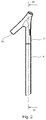
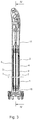
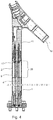
- a freestanding sanitary fitting system is shown, the above the dashboard according to Fig. 1 and a water outlet fitting 11, wherein the water outlet fitting 11 is designed in the form of a mixing fitting and has a water outlet opening 19.
- the water outlet fitting 11 is adapted for attachment to the fitting-carrying column end 2 of the supporting profile 4.
- the water outlet fitting 11 has a type of sleeve closed on one side, which is partially surrounded by the enveloping element 6 and in which the supporting profile 4 of the fitting column is fastened with screw connections 17.
- the supporting profile 4 has a ffereneinsetzrios Scheme 20, which makes it possible to insert the screws of the screw 17 in the open cavities 12 of the supporting profile 4.
- the stiffening ribs 14, which delimit the respective opening 13 of the open cavities 12, are removed by material processing on the supporting profile 4.
- the armaturtragenden column end 2 is a bottom-side column end 1 of the dashboard column, which is added in the example shown in a bottom mounting receptacle 18.
- the bottom attachment receptacle 18 has a receiving portion in the manner of a one-sided closed sleeve in which the supporting profile 4 of the fitting column is attached.
- the casing element 6 of the fitting column partially surrounds the bottom attachment receptacle 18.
- the bottom attachment receptacle 18 is fastened to a base, not shown, via screw or pin connections.
- the bottom attachment receptacle 18 has a water supply, which is connected to the water supply 3 of the fitting column at the bottom end of the column 1 is connected, wherein the water outlet fitting 11 is connected to the water supply 3 at armaturtragenden column end 2.
- Fig. 2 It can be seen that the enveloping element 6 surrounds the load-bearing profile 4 in such a way that the supporting profile 4 of the fitting column can not be seen and that a frontally contacting and aligned contact between the enveloping element 6 and the water outlet fitting 11 results.
- Fig. 3 and 4 It can be seen that a touching contact between the enveloping element 6 and the bottom mounting receptacle 18 results.
- the respective pipe / hose line 7, which is arranged in the cavity 5, is supported on at least 60% of its lateral surface by the wall of the cavity 5, more precisely by the wall of the respective subcavity.
- the compressive strength of the respective pipe / hose 7 increases.
- the invention provides a faucet column and a freestanding sanitary fitting system which reduce manufacturing and assembly costs by using a load-bearing profile consisting of an easy-to-process and inexpensive material and an enveloping element may be surrounded by a higher quality material.
Landscapes
- Health & Medical Sciences (AREA)
- Life Sciences & Earth Sciences (AREA)
- Engineering & Computer Science (AREA)
- Hydrology & Water Resources (AREA)
- Public Health (AREA)
- Water Supply & Treatment (AREA)
- Domestic Plumbing Installations (AREA)
- Toys (AREA)
Abstract
Description
- Die Erfindung betrifft eine Armaturensäule für eine freistehende Sanitärarmatur, die ein bodenseitiges und ein armaturtragendes Säulenende sowie mindestens eine sich vom bodenseitigen Säulenende bis zum armaturtragenden Säulenende erstreckende Wasserführung innerhalb der Armaturensäule aufweist, und ein damit ausgerüstetes freistehendes Sanitärarmaturensystem.
- Armaturensäulen dieser Art werden beispielsweise von der Anmelderin in Form von bodenstehenden Wannenmischern bzw. Wannenthermostaten auf dem Markt angeboten. Es ist hierfür bekannt, zwecks Stabilität relativ dickwandige Messingrohre und zur Wasserführung Kupferrohre zu verwenden. Für die Montage müssen häufig die Rohrenden nachgearbeitet werden, und es werden relativ lange Gewindestangen zur Befestigung verwendet.
- Der Erfindung liegt die Aufgabe zugrunde, eine Armaturensäule der eingangs genannten Art, die gegenüber dem oben erläuterten Stand der Technik insbesondere hinsichtlich Herstellkosten und Montageaufwand vorteilhaft ist, und ein damit ausgerüstetes Sanitärarmaturensystem bereitzustellen.
- Die Erfindung löst dieses Problem durch die Bereitstellung einer Armaturensäule mit den Merkmalen des Anspruchs 1 und eines Sanitärarmaturensystems mit den Merkmalen des Anspruchs 9. Vorteilhafte sowie bevorzugte Ausgestaltungen der Erfindung sind Gegenstand der weiteren Ansprüche, deren Wortlaut hiermit durch Verweis vollumfänglich in die Beschreibung aufgenommen wird.
- Die erfindungsgemäße Armaturensäule für eine freistehende Sanitärarmatur z.B. einer Badewanne oder eines Waschbeckens verfügt über ein bodenseitiges Säulenende und ein armaturtragendes Säulenende sowie über mindestens eine sich vom bodenseitigen Säulenende bis zum armaturtragenden Säulenende erstreckende Wasserführung innerhalb der Armaturensäule. Außerdem verfügt die Armaturensäule über ein tragendes Profil, das sich vom bodenseitigen Säulenende bis zum armaturtragenden Säulenende erstreckt. Das tragende Profil weist mindestens eine Kavität auf, welche die Wasserführung beinhaltet und sich vom bodenseitigen Säulenende bis zum armaturtragenden Säulenende erstreckt. Ferner verfügt die Armaturensäule über ein Hüllelement, welches das tragende Profil umgibt. Das tragende Profil ist, wie sein Name sagt, dafür ausgelegt, eine am armaturtragenden Säulenende zu montierende Armatur zu tragen, d.h. die entsprechenden Gewichtskräfte aufzunehmen. Somit kann das Hüllelement davon unabhängig gestaltet werden, d.h. es braucht keine Armaturtragfunktion erfüllen.
- Das bodenseitige Säulenende kann sich beispielsweise von einem bodenseitigen Stirnende der Armaturensäule bis zur Mitte der Armaturensäule erstrecken. Das armaturtragende Säulenende kann sich beispielsweise von der Mitte der Armaturensäule bis zu einem Stirnende der Armaturensäule erstrecken, das dem bodenseitigen Stirnende gegenüberliegt. Mit dem Begriff Boden ist vorliegend irgendeine Bodenfläche gemeint, an der die Armaturensäule stehend montiert werden kann bzw. soll, insbesondere eine Bodenfläche eines Duschraums oder Badezimmers oder eine ebene, horizontale Bodenfläche auf oder neben einer Badewanne oder eines Waschtischs oder Waschbeckens.
- Das tragende Profil kann beispielsweise in seinem Querschnitt eine Geometrie aufweisen, die besonders dafür geeignet ist, Querkräfte von über 100 N aufzunehmen. Das tragende Profil ist z.B. ein Metallprofil, welches als Spezialprofil oder Sonderprofil ausgebildet ist. In entsprechender Ausführung kann die Geometrie des tragenden Profils sich über die Länge der Armaturensäule verändern.
- Die Kavität kann beispielsweise ein umfangsseitig teilweise oder vollständig geschlossener Hohlraum und/oder eine umfangsseitig teilweise oder vollständig geschlossene Öffnung des tragenden Profils sein. Sie kann insbesondere dazu dienen, Wasser zu führen. Es ist möglich, dass die Wasserführung von dem bodenseitigen Säulenende zu dem armaturtragenden Säulenende durch die Kavität selbst gebildet ist. Hierfür weist dann beispielsweise die Wandung der Kavität eine Beschichtung auf, mit der ein direkter Kontakt zwischen dem in der Kavität geführten Wasser und dem Material des tragenden Profils vermieden wird. Die Kavität kann beispielsweise eine Geometrie mit mindestens zwei Subkavitäten aufweisen, die über mindestens eine Öffnung bzw. einen Spalt miteinander verbunden sind.
- Das Hüllelement kann das tragende Profil beispielsweise ganz oder nur auf einem Teil der Länge des tragenden Profils umgeben, der jeden beliebigen Wert zwischen ca. 80% und ca. 100% haben kann, wobei es sich bei Bedarf auch über die Länge des Profils hinaus erstrecken kann.
- Somit ermöglicht es der Gegenstand der Erfindung, die Herstell- und Montagekosten dadurch zu reduzieren, dass ein tragendes Profil verwendet wird, das die Wasserführung aufweist und von einem Hüllelement umgeben ist.
- In einer Ausgestaltung der Erfindung ist die Wasserführung eine Rohrleitung und/oder Schlauchleitung, die innerhalb der Kavität angeordnet ist. Dadurch kann in vorteilhafter Weise ein Kontakt zwischen dem tragenden Profil und dem in der Rohrleitung und/oder Schlauchleitung befindlichen Wasser vermieden werden. Die Schlauchleitung kann beispielsweise ein weicher Silikonschlauch sein. Die Rohrleitung kann beispielsweise ein Kunststoff-Rohr sein.
- In einer Ausgestaltung der Erfindung ist die Rohrleitung und/oder Schlauchleitung auf mindestens 60% ihrer Mantelfläche von einer Wandung der Kavität abgestützt. Dies vermeidet eine unerwünschte, fluiddruckbedingte Deformation der Rohrleitung und/oder Schlauchleitung bzw. erlaubt die Verwendung eines relativ weichen Materials geringerer Druckbelastbarkeit für die Rohrleitung bzw. Schlauchleitung. Durch die Abstützung der Rohrleitung und/oder Schlauchleitung an der Wandung der Kavität lässt sich eine höhere Druckfestigkeit der Rohrleitung und/oder Schlauchleitung erreichen. Der angegebene Prozentsatz der Mantelfläche der Rohrleitung und/oder Schlauchleitung, die von der Wandung der Kavität abgestützt ist, kann jeden beliebigen Wert in dem Bereich von 60% bis 100% haben.
- In einer Ausgestaltung der Erfindung ist das tragende Profil ein Konstruktionsprofil oder ein Profilstahl. Das Konstruktionsprofil kann beispielsweise ein steifes Profil aus Aluminium oder aus einem anderen Material hoher Biegesteifigkeit, wie z.B. einem faserverstärkten Kunststoff, sein. Das Konstruktionsprofil oder der Profilstahl können beispielsweise ein Profil aufweisen, das insbesondere für die Aufnahme von Querkräften geeignet ist und eine Kavität aufweist, die geeignet ist, Wasser zu führen und/oder die Rohrleitung und/oder die Schlauchleitung aufzunehmen.
- In einer Ausgestaltung der Erfindung ist das tragende Profil ein Strangpressprofil. Das Strangpressverfahren ermöglicht eine kostengünstige Herstellung des tragenden Profils. Des Weiteren kann das tragende Profil durch einfaches Ablängen an eine vorgegebene Länge angepasst werden.
- In einer Ausgestaltung der Erfindung ist das Hüllelement ein Dekorrohr. Das Dekorrohr kann beispielsweise eine Verkleidung sein, die als Sichtschutz wirkt und das tragende Profil verdeckt. Hierfür kann das Dekorrohr beispielsweise über Dekorelemente verfügen und/oder es ist dünnwandig aus einem hochwertigen Material hergestellt, wie z.B. Messing, Edelstahl oder einer Materialkombination hochwertiger Materialien. Um das tragende Profil zu umgeben, kann das Dekorrohr beispielsweise als Hohlprofil oder Abdeckhülse ausgeführt sein. Es ist möglich, dass das Dekorrohr das tragende Profil nach außen vollständig abdeckt.
- In einer Ausgestaltung der Erfindung weist der Querschnitt des tragenden Profils in seiner Geometrie mindestens eine Symmetrieachse auf und/oder ist punktsymmetrisch. Die Symmetrieachse und/oder die Punktsymmetrie ermöglicht es beispielsweise, Querkräfte nahezu richtungsunabhängig von dem tragenden Profil aufzunehmen. Des Weiteren vereinfacht die Symmetrieachse und/oder die Punktsymmetrie des tragenden Profils in entsprechenden Fällen die Herstellung und/oder die Montage, u.a. indem die Anzahl möglicher Einbaurichtungen reduziert wird.
- In einer Ausgestaltung der Erfindung ist das tragende Profil ein einteiliges Hohlprofil und umfasst mehrere Kavitäten. Durch die Verwendung von mehreren Kavitäten, die jeweils eine Wasserführung aufweisen, kann beispielsweise eine Wärmeübertragung zwischen den voneinander getrennten Wasserführungen reduziert oder verhindert werden. Dies betrifft insbesondere den Fall, dass möglicherweise eine Kavität Kaltwasser führt und eine andere Kavität Warmwasser.
- Ein erfindungsgemäßes freistehendes Sanitärarmaturensystem umfasst die erfindungsgemäße Armaturensäule und eine Wasserauslassarmatur, die zur Anbringung am armaturtragenden Säulenende des tragenden Profils eingerichtet ist. Des Weiteren ist das bodenseitige Säulenende der Armaturensäule zur Anbringung an einem Gebäudeboden eingerichtet. Dabei kann der Gebäudeboden beispielsweise einen Wasseranschluss aufweisen, der an die Kavität oder eine in der Kavität angeordnete Rohrleitung und/oder Schlauchleitung am bodenseitigen Säulenende angeschlossen wird, um der Armaturensäule Wasser zuzuführen, das dann an die Wasserauslassarmatur weitergeleitet wird. Die Wasserauslassarmatur ist mit dem tragenden Profil am armaturtragenden Säulenende derart verbunden, dass ihre Gewichtskraft durch das tragende Profil aufgenommen und in den Gebäudeboden eingeleitet wird.
- Vorteilhafte Ausführungsformen der Erfindung sind in den Zeichnungen dargestellt und werden im Folgenden näher erläutert. Hierbei zeigen:
- Fig. 1
- einen Querschnitt einer Armaturensäule,
- Fig. 2
- eine teilweise Seitenansicht eines freistehenden Sanitärarmaturensystems mit der Armaturensäule von
Fig. 1 , - Fig. 3
- eine Schnittansicht des Sanitärarmaturensystems längs einer Linie III-III von
Fig. 2 und - Fig. 4
- eine Schnittansicht des Sanitärarmaturensystems längs einer Linie IV-IV von
Fig. 3 . - Wie aus
Fig. 1 ersichtlich, verfügt die gezeigte Armaturensäule über ein Hüllelement 6 und ein tragendes Profil 4, wobei das tragende Profil 4 als einteiliges Hohlprofil ausgeführt ist, welches eine geschlossene Kavität 5 und eine offene Kavität 12 in zweifacher Ausführung aufweist. Das Hüllelement 6 ist das tragende Profil 4 umgebend angeordnet. - Jede der beiden offenen Kavitäten 12 ist dafür geeignet, eine Wasserführung aufzunehmen. Um das Einsetzen einer elastischen Leitung als Wasserführung zu erleichtern, verfügt jede offene Kavität 12 über je eine Öffnung 13 radial nach außen, die sich als Spalt über die gesamte Länge der Armaturensäule erstreckt. Bei Bedarf kann damit ein elastischer Schlauch oder dgl. in die offene Kavität 12 eingesetzt werden, indem dieser seitlich durch die Öffnung 13 hindurch in die offene Kavität 12 und somit in das tragende Profil 4 gedrückt wird. Alternativ und/oder zusätzlich kann die offene Kavität 12 genutzt werden, um das tragende Profil 4 mit z.B. einer Wasserauslassarmatur und/oder einem tragenden Boden mittels Schrauben und/oder Stiften zu verbinden.
- Des Weiteren ist auch die geschlossene Kavität 5 als Wasserführung oder zur Aufnahme einer wasserführenden Leitung geeignet. In der in
Fig. 1 gezeigten Ausführung verfügt die geschlossene Kavität 5 über zwei Subkavitäten, die über eine Spaltöffnung 15 miteinander verbunden sind. Die geschlossene Kavität 5 mit ihrer beiden Subkavitäten hat in ihrem Querschnitt die geometrische Form einer Acht. Beide Subkavitäten verfügen über je eine Wasserführung 3 in Form einer Rohr- oder Schlauchleitung 7 aus Kunststoff, wobei die eine Wasserführung 3 ausgebildet ist, um Warmwasser zu führen und die andere Wasserführung 3 ausgebildet ist, um Kaltwasser zu führen. Um die jeweilige Rohr-/Schlauchleitung 7 in die betreffende Subkavität einzusetzen oder zu entnehmen, ist die geschlossene Kavität 5 von mindestens einer Stirnseite des tragenden Profils 4 her zugänglich. - Das tragende Profil 4 ist ein beispielsweise aus Aluminium bestehendes Konstruktionsprofil 8, welches im Strangpressverfahren hergestellt wurde. Um die Steifigkeit und/oder Biegesteifigkeit des tragenden Profils 4 zu erhöhen, verfügt dieses über Versteifungsrippen 14. Bezogen auf einen Mittelpunkt 16 der Querschnittsgeometrie des tragenden Profils 4 erstrecken sich die Versteifungsrippen 14 in radialer Richtung. Die Versteifungsrippen 14 erlauben es dem tragenden Profil 4, höhere Querkräfte aufzunehmen. Des Weiteren ist das tragende Profil 4 einschließlich seiner Versteifungsrippen 14 in seiner Querschnittsgeometrie symmetrisch in Bezug auf zwei zueinander senkrechte Symmetrieachsen 10 und punktsymmetrisch in Bezug auf den Mittelpunkt 16.
- Das tragende Profil 4 ist von dem Hüllelement 6 umgeben, welches im gezeigten Beispiel als Dekorrohr 9 in Form eines kreiszylindrischen Rohrs ausgebildet ist. In einer nicht gezeigten Ausführung der Armaturensäule kann das Dekorrohr 9 beispielsweise einen berührenden Kontakt mit den Versteifungsrippen 14 aufweisen, welche dadurch eine abstützende und zentrierende Funktion für das Dekorrohr 9 wahrnehmen. Das Dekorrohr 9 besteht vorzugsweise aus einem höherwertigeren Material als das tragende Profil 4. Auftretende Kräfte, wie z.B. die Gewichtskraft einer Wasserauslassarmatur oder Querkräfte infolge einer Betätigung einer am tragenden Profil 4 befestigten Wasserauslassarmatur, werden überwiegend von dem tragenden Profil 4 aufgenommen. Somit nimmt das Dekorrohr 9 höchstens einen geringen Anteil, z.B. geringer als 50%, der auftretenden Kräfte auf und kann folglich materialsparend und dünnwandig, z.B. mit einer Wandstärke von weniger als 5 mm, ausgestaltet sein.
- In nicht gezeigten alternativen Ausführungsvarianten der Armaturensäule verfügt die Armaturensäule über eine einzige oder mehr als zwei Wasserführungen. Die Wasserführungen können mittels einer Rohr- oder einer Schlauchleitung oder einer Kombination beider Leitungsmöglichkeiten gebildet sein. So können bei einer Mehrzahl von Wasserführungen z.B. eine Wasserführung durch eine Schlauchleitung und die übrigen Wasserführungen durch jeweils eine Rohrleitung realisiert sein.
- In den
Fig. 2 bis 4 ist ein freistehendes Sanitärarmaturensystem gezeigt, das über die Armaturensäule gemäßFig. 1 und eine Wasserauslassarmatur 11 verfügt, wobei die Wasserauslassarmatur 11 in Form einer Mischarmatur ausgeführt ist und eine Wasseraustrittsöffnung 19 aufweist. Die Wasserauslassarmatur 11 ist zur Anbringung am armaturtragenden Säulenende 2 des tragenden Profils 4 eingerichtet. Hierzu weist die Wasserauslassarmatur 11 eine Art von einseitig geschlossener Hülse auf, die teilweise von dem Hüllelement 6 umgeben ist und in der das tragende Profil 4 der Armaturensäule mit Schraubverbindungen 17 befestigt ist. Das tragende Profil 4 weist einen Schraubeneinsetzbereich 20 auf, der es ermöglicht, die Schrauben der Schraubverbindungen 17 in die offenen Kavitäten 12 des tragenden Profils 4 einzusetzen. Dazu sind im Schraubeneinsetzbereich 20 die Versteifungsrippen 14, welche die jeweilige Öffnung 13 der offenen Kavitäten 12 begrenzen, durch Materialbearbeitung am tragenden Profil 4 entfernt. - Gegenüber dem armaturtragenden Säulenende 2 befindet sich ein bodenseitiges Säulenende 1 der Armaturensäule, das im gezeigten Beispiel in einer Bodenbefestigungsaufnahme 18 aufgenommen ist. Die Bodenbefestigungsaufnahme 18 verfügt über einen Aufnahmeabschnitt in der Art einer einseitig geschlossenen Hülse, in der das tragende Profil 4 der Armaturensäule befestigt ist. Das Hüllelement 6 der Armaturensäule umgibt dabei teilweise die Bodenbefestigungsaufnahme 18. Die Bodenbefestigungsaufnahme 18 ist an einen nicht weiter dargestellten Boden über Schraub- bzw. Stiftverbindungen befestigt. Außerdem verfügt die Bodenbefestigungsaufnahme 18 über eine Wasserzuführung, die an die Wasserführung 3 der Armaturensäule am bodenseitigen Säulenende 1 angeschlossen ist, wobei die Wasserauslassarmatur 11 mit der Wasserführung 3 am armaturtragenden Säulenende 2 verbunden ist.
- In
Fig. 2 ist erkennbar, dass das Hüllelement 6 das tragende Profil 4 derart umgibt, dass das tragende Profil 4 der Armaturensäule nicht zu sehen ist und dass sich ein stirnseitig berührender und fluchtender Kontakt zwischen dem Hüllelement 6 und der Wasserauslassarmatur 11 ergibt. In denFig. 3 und4 ist zu sehen, dass sich ein berührender Kontakt zwischen dem Hüllelement 6 und der Bodenbefestigungsaufnahme 18 ergibt. - In der gezeigten Ausführung der Armaturensäule ist die jeweilige Rohr-/Schlauchleitung 7, welche in der Kavität 5 angeordnet ist, an mindestens 60% ihrer Mantelfläche von der Wandung der Kavität 5 abgestützt, hier genauer von der Wandung der jeweiligen Subkavität. Durch die Abstützung an der Wandung der Kavität 5 erhöht sich die Druckfestigkeit der jeweiligen Rohr-/Schlauchleitung 7. Somit ist es auf Wunsch möglich, ein Material für die Rohr-/Schlauchleitung 7zu wählen, welches dem Wasserdruck ohne die Abstützung an der Kavität nicht standhalten würde.
- Wie die oben erläuterten Ausführungsbeispiele deutlich machen, stellt die Erfindung eine Armaturensäule und ein freistehendes Sanitärarmaturensystem zur Verfügung, welche die Herstell- und Montagekosten reduzieren, indem ein tragendes Profil verwendet wird, das aus einem leicht zu verarbeitenden und kostengünstigen Material bestehen und von einem Hüllelement aus einem höherwertigen Material umgeben sein kann.
Claims (9)
- Armaturensäule für eine freistehende Sanitärarmatur, mit- einem bodenseitigen Säulenende (1) und einem armaturtragenden Säulenende (2) und- mindestens einer sich vom bodenseitigen Säulenende bis zum armaturtragenden Säulenende erstreckenden Wasserführung (3) innerhalb der Armaturensäule,gekennzeichnet durch- ein tragendes Profil (4), das sich vom bodenseitigen Säulenende bis zum armarturtragenden Säulenende erstreckt,- mindestens eine Kavität (5), welche die Wasserführung aufweist und die sich vom bodenseitigen Säulenende bis zum armaturtragenden Säulenende erstreckt und vom tragenden Profil gebildet ist, und- ein Hüllelement (6), welches das tragende Profil umgibt.
- Armaturensäule nach Anspruch 1, dadurch gekennzeichnet, dass die Wasserführung eine Rohrleitung (7) und/oder Schlauchleitung ist, die in der Kavität angeordnet ist.
- Armaturensäule nach Anspruch 2, dadurch gekennzeichnet, dass die Rohrleitung und/oder Schlauchleitung in der Kavität auf mindestens 60% ihrer Mantelfläche von einer Wandung der Kavität abgestützt ist.
- Armaturensäule nach einem der vorherigen Ansprüche, dadurch gekennzeichnet, dass das tragende Profil ein Konstruktionsprofil (8) oder ein Profilstahl ist.
- Armaturensäule nach einem der vorherigen Ansprüche, dadurch gekennzeichnet, dass das tragende Profil ein Strangpressprofil ist.
- Armaturensäule nach einem der vorherigen Ansprüche, dadurch gekennzeichnet, dass das Hüllelement ein Dekorrohr (9) ist.
- Armaturensäule nach einem der vorherigen Ansprüche, dadurch gekennzeichnet, dass die Geometrie des tragenden Profils im Querschnitt mindestens eine Symmetrieachse (10) aufweist und/oder punktsymmetrisch ist.
- Armaturensäule nach einem der vorherigen Ansprüche, dadurch gekennzeichnet, dass das tragende Profil ein einteiliges Hohlprofil ist und mehrere Kavitäten umfasst.
- Freistehendes Sanitärarmaturensystem mit- einer Armaturensäule nach einem der vorherigen Ansprüche und- einer Wasserauslassarmatur (11), die zur Anbringung am armaturtragenden Säulenende des tragenden Profils eingerichtet ist,- wobei das bodenseitigen Säulenende der Armaturensäule zur Anbringung an einem Gebäudeboden eingerichtet ist.
Applications Claiming Priority (1)
| Application Number | Priority Date | Filing Date | Title |
|---|---|---|---|
| DE102016219218.3A DE102016219218A1 (de) | 2016-10-04 | 2016-10-04 | Armaturensäule und freistehendes Sanitärarmaturensystem |
Publications (2)
| Publication Number | Publication Date |
|---|---|
| EP3305996A1 true EP3305996A1 (de) | 2018-04-11 |
| EP3305996B1 EP3305996B1 (de) | 2020-08-05 |
Family
ID=60009466
Family Applications (1)
| Application Number | Title | Priority Date | Filing Date |
|---|---|---|---|
| EP17194009.1A Active EP3305996B1 (de) | 2016-10-04 | 2017-09-29 | Armaturensäule und freistehendes sanitärarmaturensystem |
Country Status (4)
| Country | Link |
|---|---|
| US (1) | US10577781B2 (de) |
| EP (1) | EP3305996B1 (de) |
| CN (1) | CN107893452B (de) |
| DE (1) | DE102016219218A1 (de) |
Citations (5)
| Publication number | Priority date | Publication date | Assignee | Title |
|---|---|---|---|---|
| CH235533A (de) * | 1942-04-09 | 1944-12-15 | Voss Erich | Freistehender Waschbrunnen. |
| DE10310256A1 (de) * | 2002-03-05 | 2003-09-18 | Ib Torbre Rubinetterie S R L | Hahn für Einloch-Spülbecken |
| EP1357233A1 (de) * | 1997-03-19 | 2003-10-29 | Inax Corporation | Wasserhahnmontageanordnung |
| DE10261798A1 (de) * | 2002-12-30 | 2004-07-15 | Hansgrohe Ag | Sanitärarmatur |
| DE102011085346A1 (de) * | 2011-10-27 | 2013-05-02 | Hansgrohe Se | Sanitärarmatur |
Family Cites Families (16)
| Publication number | Priority date | Publication date | Assignee | Title |
|---|---|---|---|---|
| US2196301A (en) | 1940-04-09 | e heine | ||
| SE506367C2 (sv) * | 1996-04-25 | 1997-12-08 | Gustavsberg Vaargaarda Armatur | Inloppsdel till en ventil |
| US6748071B2 (en) * | 2001-07-18 | 2004-06-08 | Avaya Technology Corp. | Method and apparatus for treating externally-originated calls as coming from internal switch extensions |
| CA2429796C (en) * | 2001-10-03 | 2010-11-02 | Newfrey Llc | Single control faucet installation apparatus and method |
| US6659124B2 (en) * | 2001-11-08 | 2003-12-09 | Moen Incorporated | Side spray mounting with collapsible insert |
| US7032260B2 (en) * | 2003-12-31 | 2006-04-25 | Su Hwang | Faucet with a connecting structure with a cold and a hot water pipe |
| US20080196159A1 (en) * | 2006-11-30 | 2008-08-21 | Lee William A | Method and apparatus for soft-feel plumbing fixtures |
| DE102007009409B4 (de) | 2007-02-23 | 2010-10-14 | Grohe Ag | Armatur mit Schwenkauslauf |
| TW201200249A (en) * | 2010-03-18 | 2012-01-01 | Vesuvius Crucible Co | Method and apparatus for dry-conveying material for dry gunning application |
| US8453669B2 (en) * | 2010-07-21 | 2013-06-04 | Masco Corporation Of Indiana | Waterway adapter |
| US9051719B2 (en) * | 2010-12-01 | 2015-06-09 | Globe Union Industrial Corp. | Fixing structure of faucet |
| US8584697B2 (en) * | 2012-02-02 | 2013-11-19 | Da Yuan Sheng Industrial Co. Ltd. | Faucet structure |
| US8931500B2 (en) * | 2012-02-17 | 2015-01-13 | Masco Corporation Of Indiana | Two handle centerset faucet |
| US9334634B2 (en) * | 2013-03-15 | 2016-05-10 | Kohler Co. | Mixing valve assembly for faucet |
| US10184230B2 (en) * | 2013-06-08 | 2019-01-22 | Sidus Technologies, Inc. | Mechanical touch faucet |
| EP2821556B1 (de) * | 2013-07-01 | 2017-08-30 | Franke Water Systems AG | Wasserauslaufarmatur |
-
2016
- 2016-10-04 DE DE102016219218.3A patent/DE102016219218A1/de not_active Ceased
-
2017
- 2017-09-29 US US15/720,477 patent/US10577781B2/en active Active
- 2017-09-29 EP EP17194009.1A patent/EP3305996B1/de active Active
- 2017-09-29 CN CN201710907453.6A patent/CN107893452B/zh active Active
Patent Citations (5)
| Publication number | Priority date | Publication date | Assignee | Title |
|---|---|---|---|---|
| CH235533A (de) * | 1942-04-09 | 1944-12-15 | Voss Erich | Freistehender Waschbrunnen. |
| EP1357233A1 (de) * | 1997-03-19 | 2003-10-29 | Inax Corporation | Wasserhahnmontageanordnung |
| DE10310256A1 (de) * | 2002-03-05 | 2003-09-18 | Ib Torbre Rubinetterie S R L | Hahn für Einloch-Spülbecken |
| DE10261798A1 (de) * | 2002-12-30 | 2004-07-15 | Hansgrohe Ag | Sanitärarmatur |
| DE102011085346A1 (de) * | 2011-10-27 | 2013-05-02 | Hansgrohe Se | Sanitärarmatur |
Also Published As
| Publication number | Publication date |
|---|---|
| CN107893452B (zh) | 2021-04-06 |
| US10577781B2 (en) | 2020-03-03 |
| US20180094412A1 (en) | 2018-04-05 |
| DE102016219218A1 (de) | 2018-04-05 |
| CN107893452A (zh) | 2018-04-10 |
| EP3305996B1 (de) | 2020-08-05 |
Similar Documents
| Publication | Publication Date | Title |
|---|---|---|
| EP3746609B1 (de) | Anschlussvorrichtung für eine toilettenschüssel | |
| EP2876222A1 (de) | Verdeckte Befestigungsvorrichtung für ein wandbefestigtes WC | |
| EP2182122A1 (de) | Aufputz-Brausearmatur | |
| DE112020002584T5 (de) | Verteilerrohre für eine Verteilerrohrleitung | |
| EP3415696B1 (de) | Installationselement zur befestigung eines toilettenbeckens an einer wand mit tragenden querschnittveränderlichen rahmenprofilen | |
| EP0048906A2 (de) | Rohrleitungsanordnung mit Anschlusselementen für Auslaufarmaturen | |
| DE102017123765A1 (de) | Adapter zum Anschluss einer Ventil- oder Spülarmatur an eine Rohrleitung und System mit einem solchen Adapter und einem Vorwandgestellelement | |
| EP2853650A1 (de) | Bausatz zum Verkleiden und Verrohren von Sanitärräumen | |
| EP3305996B1 (de) | Armaturensäule und freistehendes sanitärarmaturensystem | |
| EP3242978B1 (de) | S-anschluss zur verbindung einer wasserleitung mit einer armatur | |
| DE202015009052U1 (de) | Montagevorrichtung | |
| EP2072697A1 (de) | Vorrichtung mit einen Abgangsbogen und einer Rohrschelle und Montageanordnung mit einer solchen Vorrichtung | |
| EP2407603B1 (de) | Montageeinrichtung mit einem Montagegestell und Verfahren zum Montieren einer solchen Montageeinrichtung | |
| AT522031B1 (de) | Wasseranschlusssystem | |
| EP4306728A1 (de) | Sanitärwanneninstallation und installationseinrichtung | |
| DE102012201693B4 (de) | Adapterelement | |
| EP3441535B1 (de) | Vorrichtung zur befestigung einer sanitäreinheit | |
| DE102021117601A1 (de) | Waschbecken für Räume mit erhöhten Hygieneanforderungen und Waschtisch | |
| DE102011052814A1 (de) | Badewanne | |
| DE202015100115U1 (de) | Lehnenanordnung | |
| DE202009002502U1 (de) | Waschtischeinrichtung mit Konsole | |
| WO2022122491A1 (de) | Montagevorrichtung | |
| DE20007445U1 (de) | Raum-Modul-System sowie Tragsäule und Strangpressprofil | |
| DE2415019C2 (de) | Vorrichtung zur Halterung von sanitären Einrichtungen oder Installationen | |
| AT527672A4 (de) | Halteanordnung zur Verwendung in einer Vorwandinstallation |
Legal Events
| Date | Code | Title | Description |
|---|---|---|---|
| PUAI | Public reference made under article 153(3) epc to a published international application that has entered the european phase |
Free format text: ORIGINAL CODE: 0009012 |
|
| STAA | Information on the status of an ep patent application or granted ep patent |
Free format text: STATUS: THE APPLICATION HAS BEEN PUBLISHED |
|
| AK | Designated contracting states |
Kind code of ref document: A1 Designated state(s): AL AT BE BG CH CY CZ DE DK EE ES FI FR GB GR HR HU IE IS IT LI LT LU LV MC MK MT NL NO PL PT RO RS SE SI SK SM TR |
|
| AX | Request for extension of the european patent |
Extension state: BA ME |
|
| STAA | Information on the status of an ep patent application or granted ep patent |
Free format text: STATUS: REQUEST FOR EXAMINATION WAS MADE |
|
| 17P | Request for examination filed |
Effective date: 20181008 |
|
| RBV | Designated contracting states (corrected) |
Designated state(s): AL AT BE BG CH CY CZ DE DK EE ES FI FR GB GR HR HU IE IS IT LI LT LU LV MC MK MT NL NO PL PT RO RS SE SI SK SM TR |
|
| GRAP | Despatch of communication of intention to grant a patent |
Free format text: ORIGINAL CODE: EPIDOSNIGR1 |
|
| STAA | Information on the status of an ep patent application or granted ep patent |
Free format text: STATUS: GRANT OF PATENT IS INTENDED |
|
| INTG | Intention to grant announced |
Effective date: 20200325 |
|
| GRAS | Grant fee paid |
Free format text: ORIGINAL CODE: EPIDOSNIGR3 |
|
| GRAA | (expected) grant |
Free format text: ORIGINAL CODE: 0009210 |
|
| STAA | Information on the status of an ep patent application or granted ep patent |
Free format text: STATUS: THE PATENT HAS BEEN GRANTED |
|
| AK | Designated contracting states |
Kind code of ref document: B1 Designated state(s): AL AT BE BG CH CY CZ DE DK EE ES FI FR GB GR HR HU IE IS IT LI LT LU LV MC MK MT NL NO PL PT RO RS SE SI SK SM TR |
|
| REG | Reference to a national code |
Ref country code: GB Ref legal event code: FG4D Free format text: NOT ENGLISH |
|
| REG | Reference to a national code |
Ref country code: CH Ref legal event code: EP |
|
| REG | Reference to a national code |
Ref country code: AT Ref legal event code: REF Ref document number: 1298879 Country of ref document: AT Kind code of ref document: T Effective date: 20200815 |
|
| REG | Reference to a national code |
Ref country code: DE Ref legal event code: R096 Ref document number: 502017006530 Country of ref document: DE |
|
| REG | Reference to a national code |
Ref country code: IE Ref legal event code: FG4D Free format text: LANGUAGE OF EP DOCUMENT: GERMAN |
|
| REG | Reference to a national code |
Ref country code: LT Ref legal event code: MG4D |
|
| REG | Reference to a national code |
Ref country code: NL Ref legal event code: MP Effective date: 20200805 |
|
| PG25 | Lapsed in a contracting state [announced via postgrant information from national office to epo] |
Ref country code: FI Free format text: LAPSE BECAUSE OF FAILURE TO SUBMIT A TRANSLATION OF THE DESCRIPTION OR TO PAY THE FEE WITHIN THE PRESCRIBED TIME-LIMIT Effective date: 20200805 Ref country code: LT Free format text: LAPSE BECAUSE OF FAILURE TO SUBMIT A TRANSLATION OF THE DESCRIPTION OR TO PAY THE FEE WITHIN THE PRESCRIBED TIME-LIMIT Effective date: 20200805 Ref country code: BG Free format text: LAPSE BECAUSE OF FAILURE TO SUBMIT A TRANSLATION OF THE DESCRIPTION OR TO PAY THE FEE WITHIN THE PRESCRIBED TIME-LIMIT Effective date: 20201105 Ref country code: ES Free format text: LAPSE BECAUSE OF FAILURE TO SUBMIT A TRANSLATION OF THE DESCRIPTION OR TO PAY THE FEE WITHIN THE PRESCRIBED TIME-LIMIT Effective date: 20200805 Ref country code: NO Free format text: LAPSE BECAUSE OF FAILURE TO SUBMIT A TRANSLATION OF THE DESCRIPTION OR TO PAY THE FEE WITHIN THE PRESCRIBED TIME-LIMIT Effective date: 20201105 Ref country code: GR Free format text: LAPSE BECAUSE OF FAILURE TO SUBMIT A TRANSLATION OF THE DESCRIPTION OR TO PAY THE FEE WITHIN THE PRESCRIBED TIME-LIMIT Effective date: 20201106 Ref country code: PT Free format text: LAPSE BECAUSE OF FAILURE TO SUBMIT A TRANSLATION OF THE DESCRIPTION OR TO PAY THE FEE WITHIN THE PRESCRIBED TIME-LIMIT Effective date: 20201207 Ref country code: HR Free format text: LAPSE BECAUSE OF FAILURE TO SUBMIT A TRANSLATION OF THE DESCRIPTION OR TO PAY THE FEE WITHIN THE PRESCRIBED TIME-LIMIT Effective date: 20200805 Ref country code: SE Free format text: LAPSE BECAUSE OF FAILURE TO SUBMIT A TRANSLATION OF THE DESCRIPTION OR TO PAY THE FEE WITHIN THE PRESCRIBED TIME-LIMIT Effective date: 20200805 |
|
| PG25 | Lapsed in a contracting state [announced via postgrant information from national office to epo] |
Ref country code: RS Free format text: LAPSE BECAUSE OF FAILURE TO SUBMIT A TRANSLATION OF THE DESCRIPTION OR TO PAY THE FEE WITHIN THE PRESCRIBED TIME-LIMIT Effective date: 20200805 Ref country code: LV Free format text: LAPSE BECAUSE OF FAILURE TO SUBMIT A TRANSLATION OF THE DESCRIPTION OR TO PAY THE FEE WITHIN THE PRESCRIBED TIME-LIMIT Effective date: 20200805 Ref country code: NL Free format text: LAPSE BECAUSE OF FAILURE TO SUBMIT A TRANSLATION OF THE DESCRIPTION OR TO PAY THE FEE WITHIN THE PRESCRIBED TIME-LIMIT Effective date: 20200805 Ref country code: PL Free format text: LAPSE BECAUSE OF FAILURE TO SUBMIT A TRANSLATION OF THE DESCRIPTION OR TO PAY THE FEE WITHIN THE PRESCRIBED TIME-LIMIT Effective date: 20200805 Ref country code: IS Free format text: LAPSE BECAUSE OF FAILURE TO SUBMIT A TRANSLATION OF THE DESCRIPTION OR TO PAY THE FEE WITHIN THE PRESCRIBED TIME-LIMIT Effective date: 20201205 |
|
| PG25 | Lapsed in a contracting state [announced via postgrant information from national office to epo] |
Ref country code: RO Free format text: LAPSE BECAUSE OF FAILURE TO SUBMIT A TRANSLATION OF THE DESCRIPTION OR TO PAY THE FEE WITHIN THE PRESCRIBED TIME-LIMIT Effective date: 20200805 Ref country code: CZ Free format text: LAPSE BECAUSE OF FAILURE TO SUBMIT A TRANSLATION OF THE DESCRIPTION OR TO PAY THE FEE WITHIN THE PRESCRIBED TIME-LIMIT Effective date: 20200805 Ref country code: DK Free format text: LAPSE BECAUSE OF FAILURE TO SUBMIT A TRANSLATION OF THE DESCRIPTION OR TO PAY THE FEE WITHIN THE PRESCRIBED TIME-LIMIT Effective date: 20200805 Ref country code: EE Free format text: LAPSE BECAUSE OF FAILURE TO SUBMIT A TRANSLATION OF THE DESCRIPTION OR TO PAY THE FEE WITHIN THE PRESCRIBED TIME-LIMIT Effective date: 20200805 Ref country code: SM Free format text: LAPSE BECAUSE OF FAILURE TO SUBMIT A TRANSLATION OF THE DESCRIPTION OR TO PAY THE FEE WITHIN THE PRESCRIBED TIME-LIMIT Effective date: 20200805 |
|
| REG | Reference to a national code |
Ref country code: CH Ref legal event code: PL |
|
| REG | Reference to a national code |
Ref country code: DE Ref legal event code: R097 Ref document number: 502017006530 Country of ref document: DE |
|
| PG25 | Lapsed in a contracting state [announced via postgrant information from national office to epo] |
Ref country code: MC Free format text: LAPSE BECAUSE OF FAILURE TO SUBMIT A TRANSLATION OF THE DESCRIPTION OR TO PAY THE FEE WITHIN THE PRESCRIBED TIME-LIMIT Effective date: 20200805 Ref country code: AL Free format text: LAPSE BECAUSE OF FAILURE TO SUBMIT A TRANSLATION OF THE DESCRIPTION OR TO PAY THE FEE WITHIN THE PRESCRIBED TIME-LIMIT Effective date: 20200805 |
|
| PLBE | No opposition filed within time limit |
Free format text: ORIGINAL CODE: 0009261 |
|
| STAA | Information on the status of an ep patent application or granted ep patent |
Free format text: STATUS: NO OPPOSITION FILED WITHIN TIME LIMIT |
|
| REG | Reference to a national code |
Ref country code: BE Ref legal event code: MM Effective date: 20200930 |
|
| PG25 | Lapsed in a contracting state [announced via postgrant information from national office to epo] |
Ref country code: LU Free format text: LAPSE BECAUSE OF NON-PAYMENT OF DUE FEES Effective date: 20200929 Ref country code: SK Free format text: LAPSE BECAUSE OF FAILURE TO SUBMIT A TRANSLATION OF THE DESCRIPTION OR TO PAY THE FEE WITHIN THE PRESCRIBED TIME-LIMIT Effective date: 20200805 |
|
| 26N | No opposition filed |
Effective date: 20210507 |
|
| PG25 | Lapsed in a contracting state [announced via postgrant information from national office to epo] |
Ref country code: SI Free format text: LAPSE BECAUSE OF FAILURE TO SUBMIT A TRANSLATION OF THE DESCRIPTION OR TO PAY THE FEE WITHIN THE PRESCRIBED TIME-LIMIT Effective date: 20200805 Ref country code: LI Free format text: LAPSE BECAUSE OF NON-PAYMENT OF DUE FEES Effective date: 20200930 Ref country code: IE Free format text: LAPSE BECAUSE OF NON-PAYMENT OF DUE FEES Effective date: 20200929 Ref country code: BE Free format text: LAPSE BECAUSE OF NON-PAYMENT OF DUE FEES Effective date: 20200930 Ref country code: CH Free format text: LAPSE BECAUSE OF NON-PAYMENT OF DUE FEES Effective date: 20200930 |
|
| PG25 | Lapsed in a contracting state [announced via postgrant information from national office to epo] |
Ref country code: TR Free format text: LAPSE BECAUSE OF FAILURE TO SUBMIT A TRANSLATION OF THE DESCRIPTION OR TO PAY THE FEE WITHIN THE PRESCRIBED TIME-LIMIT Effective date: 20200805 Ref country code: MT Free format text: LAPSE BECAUSE OF FAILURE TO SUBMIT A TRANSLATION OF THE DESCRIPTION OR TO PAY THE FEE WITHIN THE PRESCRIBED TIME-LIMIT Effective date: 20200805 Ref country code: CY Free format text: LAPSE BECAUSE OF FAILURE TO SUBMIT A TRANSLATION OF THE DESCRIPTION OR TO PAY THE FEE WITHIN THE PRESCRIBED TIME-LIMIT Effective date: 20200805 |
|
| PG25 | Lapsed in a contracting state [announced via postgrant information from national office to epo] |
Ref country code: MK Free format text: LAPSE BECAUSE OF FAILURE TO SUBMIT A TRANSLATION OF THE DESCRIPTION OR TO PAY THE FEE WITHIN THE PRESCRIBED TIME-LIMIT Effective date: 20200805 |
|
| REG | Reference to a national code |
Ref country code: AT Ref legal event code: MM01 Ref document number: 1298879 Country of ref document: AT Kind code of ref document: T Effective date: 20220929 |
|
| PG25 | Lapsed in a contracting state [announced via postgrant information from national office to epo] |
Ref country code: AT Free format text: LAPSE BECAUSE OF NON-PAYMENT OF DUE FEES Effective date: 20220929 |
|
| PGFP | Annual fee paid to national office [announced via postgrant information from national office to epo] |
Ref country code: DE Payment date: 20250926 Year of fee payment: 9 |
|
| PGFP | Annual fee paid to national office [announced via postgrant information from national office to epo] |
Ref country code: IT Payment date: 20250922 Year of fee payment: 9 |
|
| PGFP | Annual fee paid to national office [announced via postgrant information from national office to epo] |
Ref country code: GB Payment date: 20250923 Year of fee payment: 9 |
|
| PGFP | Annual fee paid to national office [announced via postgrant information from national office to epo] |
Ref country code: FR Payment date: 20250925 Year of fee payment: 9 |