EP3305583A1 - Display device for electric vehicle - Google Patents
Display device for electric vehicle Download PDFInfo
- Publication number
- EP3305583A1 EP3305583A1 EP17190440.2A EP17190440A EP3305583A1 EP 3305583 A1 EP3305583 A1 EP 3305583A1 EP 17190440 A EP17190440 A EP 17190440A EP 3305583 A1 EP3305583 A1 EP 3305583A1
- Authority
- EP
- European Patent Office
- Prior art keywords
- power consumption
- consumption rate
- scale
- travel range
- possible travel
- Prior art date
- Legal status (The legal status is an assumption and is not a legal conclusion. Google has not performed a legal analysis and makes no representation as to the accuracy of the status listed.)
- Withdrawn
Links
Images


Classifications
-
- B—PERFORMING OPERATIONS; TRANSPORTING
- B60—VEHICLES IN GENERAL
- B60L—PROPULSION OF ELECTRICALLY-PROPELLED VEHICLES; SUPPLYING ELECTRIC POWER FOR AUXILIARY EQUIPMENT OF ELECTRICALLY-PROPELLED VEHICLES; ELECTRODYNAMIC BRAKE SYSTEMS FOR VEHICLES IN GENERAL; MAGNETIC SUSPENSION OR LEVITATION FOR VEHICLES; MONITORING OPERATING VARIABLES OF ELECTRICALLY-PROPELLED VEHICLES; ELECTRIC SAFETY DEVICES FOR ELECTRICALLY-PROPELLED VEHICLES
- B60L3/00—Electric devices on electrically-propelled vehicles for safety purposes; Monitoring operating variables, e.g. speed, deceleration or energy consumption
- B60L3/12—Recording operating variables ; Monitoring of operating variables
-
- G—PHYSICS
- G05—CONTROLLING; REGULATING
- G05B—CONTROL OR REGULATING SYSTEMS IN GENERAL; FUNCTIONAL ELEMENTS OF SUCH SYSTEMS; MONITORING OR TESTING ARRANGEMENTS FOR SUCH SYSTEMS OR ELEMENTS
- G05B19/00—Program-control systems
- G05B19/02—Program-control systems electric
- G05B19/04—Program control other than numerical control, i.e. in sequence controllers or logic controllers
- G05B19/042—Program control other than numerical control, i.e. in sequence controllers or logic controllers using digital processors
- G05B19/0428—Safety, monitoring
-
- B—PERFORMING OPERATIONS; TRANSPORTING
- B60—VEHICLES IN GENERAL
- B60K—ARRANGEMENT OR MOUNTING OF PROPULSION UNITS OR OF TRANSMISSIONS IN VEHICLES; ARRANGEMENT OR MOUNTING OF PLURAL DIVERSE PRIME-MOVERS IN VEHICLES; AUXILIARY DRIVES FOR VEHICLES; INSTRUMENTATION OR DASHBOARDS FOR VEHICLES; ARRANGEMENTS IN CONNECTION WITH COOLING, AIR INTAKE, GAS EXHAUST OR FUEL SUPPLY OF PROPULSION UNITS IN VEHICLES
- B60K35/00—Instruments specially adapted for vehicles; Arrangement of instruments in or on vehicles
- B60K35/10—Input arrangements, i.e. from user to vehicle, associated with vehicle functions or specially adapted therefor
-
- B—PERFORMING OPERATIONS; TRANSPORTING
- B60—VEHICLES IN GENERAL
- B60K—ARRANGEMENT OR MOUNTING OF PROPULSION UNITS OR OF TRANSMISSIONS IN VEHICLES; ARRANGEMENT OR MOUNTING OF PLURAL DIVERSE PRIME-MOVERS IN VEHICLES; AUXILIARY DRIVES FOR VEHICLES; INSTRUMENTATION OR DASHBOARDS FOR VEHICLES; ARRANGEMENTS IN CONNECTION WITH COOLING, AIR INTAKE, GAS EXHAUST OR FUEL SUPPLY OF PROPULSION UNITS IN VEHICLES
- B60K35/00—Instruments specially adapted for vehicles; Arrangement of instruments in or on vehicles
- B60K35/20—Output arrangements, i.e. from vehicle to user, associated with vehicle functions or specially adapted therefor
- B60K35/21—Output arrangements, i.e. from vehicle to user, associated with vehicle functions or specially adapted therefor using visual output, e.g. blinking lights or matrix displays
- B60K35/214—Variable gauge scales, e.g. scale enlargement to adapt to maximum driving speed
-
- B—PERFORMING OPERATIONS; TRANSPORTING
- B60—VEHICLES IN GENERAL
- B60K—ARRANGEMENT OR MOUNTING OF PROPULSION UNITS OR OF TRANSMISSIONS IN VEHICLES; ARRANGEMENT OR MOUNTING OF PLURAL DIVERSE PRIME-MOVERS IN VEHICLES; AUXILIARY DRIVES FOR VEHICLES; INSTRUMENTATION OR DASHBOARDS FOR VEHICLES; ARRANGEMENTS IN CONNECTION WITH COOLING, AIR INTAKE, GAS EXHAUST OR FUEL SUPPLY OF PROPULSION UNITS IN VEHICLES
- B60K35/00—Instruments specially adapted for vehicles; Arrangement of instruments in or on vehicles
- B60K35/20—Output arrangements, i.e. from vehicle to user, associated with vehicle functions or specially adapted therefor
- B60K35/21—Output arrangements, i.e. from vehicle to user, associated with vehicle functions or specially adapted therefor using visual output, e.g. blinking lights or matrix displays
- B60K35/22—Display screens
-
- B—PERFORMING OPERATIONS; TRANSPORTING
- B60—VEHICLES IN GENERAL
- B60K—ARRANGEMENT OR MOUNTING OF PROPULSION UNITS OR OF TRANSMISSIONS IN VEHICLES; ARRANGEMENT OR MOUNTING OF PLURAL DIVERSE PRIME-MOVERS IN VEHICLES; AUXILIARY DRIVES FOR VEHICLES; INSTRUMENTATION OR DASHBOARDS FOR VEHICLES; ARRANGEMENTS IN CONNECTION WITH COOLING, AIR INTAKE, GAS EXHAUST OR FUEL SUPPLY OF PROPULSION UNITS IN VEHICLES
- B60K35/00—Instruments specially adapted for vehicles; Arrangement of instruments in or on vehicles
- B60K35/20—Output arrangements, i.e. from vehicle to user, associated with vehicle functions or specially adapted therefor
- B60K35/28—Output arrangements, i.e. from vehicle to user, associated with vehicle functions or specially adapted therefor characterised by the type of the output information, e.g. video entertainment or vehicle dynamics information; characterised by the purpose of the output information, e.g. for attracting the attention of the driver
-
- B—PERFORMING OPERATIONS; TRANSPORTING
- B60—VEHICLES IN GENERAL
- B60L—PROPULSION OF ELECTRICALLY-PROPELLED VEHICLES; SUPPLYING ELECTRIC POWER FOR AUXILIARY EQUIPMENT OF ELECTRICALLY-PROPELLED VEHICLES; ELECTRODYNAMIC BRAKE SYSTEMS FOR VEHICLES IN GENERAL; MAGNETIC SUSPENSION OR LEVITATION FOR VEHICLES; MONITORING OPERATING VARIABLES OF ELECTRICALLY-PROPELLED VEHICLES; ELECTRIC SAFETY DEVICES FOR ELECTRICALLY-PROPELLED VEHICLES
- B60L15/00—Methods, circuits, or devices for controlling the traction-motor speed of electrically-propelled vehicles
- B60L15/20—Methods, circuits, or devices for controlling the traction-motor speed of electrically-propelled vehicles for control of the vehicle or its driving motor to achieve a desired performance, e.g. speed, torque, programmed variation of speed
-
- B—PERFORMING OPERATIONS; TRANSPORTING
- B60—VEHICLES IN GENERAL
- B60L—PROPULSION OF ELECTRICALLY-PROPELLED VEHICLES; SUPPLYING ELECTRIC POWER FOR AUXILIARY EQUIPMENT OF ELECTRICALLY-PROPELLED VEHICLES; ELECTRODYNAMIC BRAKE SYSTEMS FOR VEHICLES IN GENERAL; MAGNETIC SUSPENSION OR LEVITATION FOR VEHICLES; MONITORING OPERATING VARIABLES OF ELECTRICALLY-PROPELLED VEHICLES; ELECTRIC SAFETY DEVICES FOR ELECTRICALLY-PROPELLED VEHICLES
- B60L58/00—Methods or circuit arrangements for monitoring or controlling batteries or fuel cells, specially adapted for electric vehicles
- B60L58/10—Methods or circuit arrangements for monitoring or controlling batteries or fuel cells, specially adapted for electric vehicles for monitoring or controlling batteries
-
- G—PHYSICS
- G01—MEASURING; TESTING
- G01D—MEASURING NOT SPECIALLY ADAPTED FOR A SPECIFIC VARIABLE; ARRANGEMENTS FOR MEASURING TWO OR MORE VARIABLES NOT COVERED IN A SINGLE OTHER SUBCLASS; TARIFF METERING APPARATUS; MEASURING OR TESTING NOT OTHERWISE PROVIDED FOR
- G01D7/00—Indicating measured values
- G01D7/02—Indicating value of two or more variables simultaneously
-
- G—PHYSICS
- G01—MEASURING; TESTING
- G01L—MEASURING FORCE, STRESS, TORQUE, WORK, MECHANICAL POWER, MECHANICAL EFFICIENCY, OR FLUID PRESSURE
- G01L7/00—Measuring the steady or quasi-steady pressure of a fluid or a fluent solid material by mechanical or fluid pressure-sensitive elements
- G01L7/02—Measuring the steady or quasi-steady pressure of a fluid or a fluent solid material by mechanical or fluid pressure-sensitive elements in the form of elastically-deformable gauges
-
- G—PHYSICS
- G01—MEASURING; TESTING
- G01R—MEASURING ELECTRIC VARIABLES; MEASURING MAGNETIC VARIABLES
- G01R31/00—Arrangements for testing electric properties; Arrangements for locating electric faults; Arrangements for electrical testing characterised by what is being tested not provided for elsewhere
- G01R31/36—Arrangements for testing, measuring or monitoring the electrical condition of accumulators or electric batteries, e.g. capacity or state of charge [SoC]
- G01R31/367—Software therefor, e.g. for battery testing using modelling or look-up tables
-
- G—PHYSICS
- G01—MEASURING; TESTING
- G01R—MEASURING ELECTRIC VARIABLES; MEASURING MAGNETIC VARIABLES
- G01R31/00—Arrangements for testing electric properties; Arrangements for locating electric faults; Arrangements for electrical testing characterised by what is being tested not provided for elsewhere
- G01R31/36—Arrangements for testing, measuring or monitoring the electrical condition of accumulators or electric batteries, e.g. capacity or state of charge [SoC]
- G01R31/396—Acquisition or processing of data for testing or for monitoring individual cells or groups of cells within a battery
-
- G—PHYSICS
- G07—CHECKING-DEVICES
- G07C—TIME OR ATTENDANCE REGISTERS; REGISTERING OR INDICATING THE WORKING OF MACHINES; GENERATING RANDOM NUMBERS; VOTING OR LOTTERY APPARATUS; ARRANGEMENTS, SYSTEMS OR APPARATUS FOR CHECKING NOT PROVIDED FOR ELSEWHERE
- G07C5/00—Registering or indicating the working of vehicles
- G07C5/08—Registering or indicating performance data other than driving, working, idle, or waiting time, with or without registering driving, working, idle or waiting time
- G07C5/0816—Indicating performance data, e.g. occurrence of a malfunction
- G07C5/0825—Indicating performance data, e.g. occurrence of a malfunction using optical means
-
- B—PERFORMING OPERATIONS; TRANSPORTING
- B60—VEHICLES IN GENERAL
- B60K—ARRANGEMENT OR MOUNTING OF PROPULSION UNITS OR OF TRANSMISSIONS IN VEHICLES; ARRANGEMENT OR MOUNTING OF PLURAL DIVERSE PRIME-MOVERS IN VEHICLES; AUXILIARY DRIVES FOR VEHICLES; INSTRUMENTATION OR DASHBOARDS FOR VEHICLES; ARRANGEMENTS IN CONNECTION WITH COOLING, AIR INTAKE, GAS EXHAUST OR FUEL SUPPLY OF PROPULSION UNITS IN VEHICLES
- B60K2360/00—Indexing scheme associated with groups B60K35/00 or B60K37/00 relating to details of instruments or dashboards
- B60K2360/16—Type of output information
- B60K2360/168—Target or limit values
-
- B—PERFORMING OPERATIONS; TRANSPORTING
- B60—VEHICLES IN GENERAL
- B60K—ARRANGEMENT OR MOUNTING OF PROPULSION UNITS OR OF TRANSMISSIONS IN VEHICLES; ARRANGEMENT OR MOUNTING OF PLURAL DIVERSE PRIME-MOVERS IN VEHICLES; AUXILIARY DRIVES FOR VEHICLES; INSTRUMENTATION OR DASHBOARDS FOR VEHICLES; ARRANGEMENTS IN CONNECTION WITH COOLING, AIR INTAKE, GAS EXHAUST OR FUEL SUPPLY OF PROPULSION UNITS IN VEHICLES
- B60K2360/00—Indexing scheme associated with groups B60K35/00 or B60K37/00 relating to details of instruments or dashboards
- B60K2360/16—Type of output information
- B60K2360/169—Remaining operating distance or charge
-
- B—PERFORMING OPERATIONS; TRANSPORTING
- B60—VEHICLES IN GENERAL
- B60K—ARRANGEMENT OR MOUNTING OF PROPULSION UNITS OR OF TRANSMISSIONS IN VEHICLES; ARRANGEMENT OR MOUNTING OF PLURAL DIVERSE PRIME-MOVERS IN VEHICLES; AUXILIARY DRIVES FOR VEHICLES; INSTRUMENTATION OR DASHBOARDS FOR VEHICLES; ARRANGEMENTS IN CONNECTION WITH COOLING, AIR INTAKE, GAS EXHAUST OR FUEL SUPPLY OF PROPULSION UNITS IN VEHICLES
- B60K2360/00—Indexing scheme associated with groups B60K35/00 or B60K37/00 relating to details of instruments or dashboards
- B60K2360/16—Type of output information
- B60K2360/174—Economic driving
-
- B—PERFORMING OPERATIONS; TRANSPORTING
- B60—VEHICLES IN GENERAL
- B60K—ARRANGEMENT OR MOUNTING OF PROPULSION UNITS OR OF TRANSMISSIONS IN VEHICLES; ARRANGEMENT OR MOUNTING OF PLURAL DIVERSE PRIME-MOVERS IN VEHICLES; AUXILIARY DRIVES FOR VEHICLES; INSTRUMENTATION OR DASHBOARDS FOR VEHICLES; ARRANGEMENTS IN CONNECTION WITH COOLING, AIR INTAKE, GAS EXHAUST OR FUEL SUPPLY OF PROPULSION UNITS IN VEHICLES
- B60K35/00—Instruments specially adapted for vehicles; Arrangement of instruments in or on vehicles
- B60K35/20—Output arrangements, i.e. from vehicle to user, associated with vehicle functions or specially adapted therefor
- B60K35/29—Instruments characterised by the way in which information is handled, e.g. showing information on plural displays or prioritising information according to driving conditions
-
- B—PERFORMING OPERATIONS; TRANSPORTING
- B60—VEHICLES IN GENERAL
- B60K—ARRANGEMENT OR MOUNTING OF PROPULSION UNITS OR OF TRANSMISSIONS IN VEHICLES; ARRANGEMENT OR MOUNTING OF PLURAL DIVERSE PRIME-MOVERS IN VEHICLES; AUXILIARY DRIVES FOR VEHICLES; INSTRUMENTATION OR DASHBOARDS FOR VEHICLES; ARRANGEMENTS IN CONNECTION WITH COOLING, AIR INTAKE, GAS EXHAUST OR FUEL SUPPLY OF PROPULSION UNITS IN VEHICLES
- B60K35/00—Instruments specially adapted for vehicles; Arrangement of instruments in or on vehicles
- B60K35/80—Arrangements for controlling instruments
-
- B—PERFORMING OPERATIONS; TRANSPORTING
- B60—VEHICLES IN GENERAL
- B60L—PROPULSION OF ELECTRICALLY-PROPELLED VEHICLES; SUPPLYING ELECTRIC POWER FOR AUXILIARY EQUIPMENT OF ELECTRICALLY-PROPELLED VEHICLES; ELECTRODYNAMIC BRAKE SYSTEMS FOR VEHICLES IN GENERAL; MAGNETIC SUSPENSION OR LEVITATION FOR VEHICLES; MONITORING OPERATING VARIABLES OF ELECTRICALLY-PROPELLED VEHICLES; ELECTRIC SAFETY DEVICES FOR ELECTRICALLY-PROPELLED VEHICLES
- B60L2250/00—Driver interactions
- B60L2250/16—Driver interactions by display
-
- B—PERFORMING OPERATIONS; TRANSPORTING
- B60—VEHICLES IN GENERAL
- B60L—PROPULSION OF ELECTRICALLY-PROPELLED VEHICLES; SUPPLYING ELECTRIC POWER FOR AUXILIARY EQUIPMENT OF ELECTRICALLY-PROPELLED VEHICLES; ELECTRODYNAMIC BRAKE SYSTEMS FOR VEHICLES IN GENERAL; MAGNETIC SUSPENSION OR LEVITATION FOR VEHICLES; MONITORING OPERATING VARIABLES OF ELECTRICALLY-PROPELLED VEHICLES; ELECTRIC SAFETY DEVICES FOR ELECTRICALLY-PROPELLED VEHICLES
- B60L2260/00—Operating Modes
- B60L2260/40—Control modes
- B60L2260/50—Control modes by future state prediction
- B60L2260/52—Control modes by future state prediction drive range estimation, e.g. of estimation of available travel distance
-
- B—PERFORMING OPERATIONS; TRANSPORTING
- B60—VEHICLES IN GENERAL
- B60L—PROPULSION OF ELECTRICALLY-PROPELLED VEHICLES; SUPPLYING ELECTRIC POWER FOR AUXILIARY EQUIPMENT OF ELECTRICALLY-PROPELLED VEHICLES; ELECTRODYNAMIC BRAKE SYSTEMS FOR VEHICLES IN GENERAL; MAGNETIC SUSPENSION OR LEVITATION FOR VEHICLES; MONITORING OPERATING VARIABLES OF ELECTRICALLY-PROPELLED VEHICLES; ELECTRIC SAFETY DEVICES FOR ELECTRICALLY-PROPELLED VEHICLES
- B60L2260/00—Operating Modes
- B60L2260/40—Control modes
- B60L2260/50—Control modes by future state prediction
- B60L2260/54—Energy consumption estimation
-
- G—PHYSICS
- G05—CONTROLLING; REGULATING
- G05B—CONTROL OR REGULATING SYSTEMS IN GENERAL; FUNCTIONAL ELEMENTS OF SUCH SYSTEMS; MONITORING OR TESTING ARRANGEMENTS FOR SUCH SYSTEMS OR ELEMENTS
- G05B2219/00—Program-control systems
- G05B2219/20—Pc systems
- G05B2219/26—Pc applications
- G05B2219/2637—Vehicle, car, auto, wheelchair
-
- G—PHYSICS
- G05—CONTROLLING; REGULATING
- G05B—CONTROL OR REGULATING SYSTEMS IN GENERAL; FUNCTIONAL ELEMENTS OF SUCH SYSTEMS; MONITORING OR TESTING ARRANGEMENTS FOR SUCH SYSTEMS OR ELEMENTS
- G05B2219/00—Program-control systems
- G05B2219/20—Pc systems
- G05B2219/26—Pc applications
- G05B2219/2639—Energy management, use maximum of cheap power, keep peak load low
-
- Y—GENERAL TAGGING OF NEW TECHNOLOGICAL DEVELOPMENTS; GENERAL TAGGING OF CROSS-SECTIONAL TECHNOLOGIES SPANNING OVER SEVERAL SECTIONS OF THE IPC; TECHNICAL SUBJECTS COVERED BY FORMER USPC CROSS-REFERENCE ART COLLECTIONS [XRACs] AND DIGESTS
- Y02—TECHNOLOGIES OR APPLICATIONS FOR MITIGATION OR ADAPTATION AGAINST CLIMATE CHANGE
- Y02T—CLIMATE CHANGE MITIGATION TECHNOLOGIES RELATED TO TRANSPORTATION
- Y02T10/00—Road transport of goods or passengers
- Y02T10/60—Other road transportation technologies with climate change mitigation effect
- Y02T10/64—Electric machine technologies in electromobility
-
- Y—GENERAL TAGGING OF NEW TECHNOLOGICAL DEVELOPMENTS; GENERAL TAGGING OF CROSS-SECTIONAL TECHNOLOGIES SPANNING OVER SEVERAL SECTIONS OF THE IPC; TECHNICAL SUBJECTS COVERED BY FORMER USPC CROSS-REFERENCE ART COLLECTIONS [XRACs] AND DIGESTS
- Y02—TECHNOLOGIES OR APPLICATIONS FOR MITIGATION OR ADAPTATION AGAINST CLIMATE CHANGE
- Y02T—CLIMATE CHANGE MITIGATION TECHNOLOGIES RELATED TO TRANSPORTATION
- Y02T10/00—Road transport of goods or passengers
- Y02T10/60—Other road transportation technologies with climate change mitigation effect
- Y02T10/70—Energy storage systems for electromobility, e.g. batteries
-
- Y—GENERAL TAGGING OF NEW TECHNOLOGICAL DEVELOPMENTS; GENERAL TAGGING OF CROSS-SECTIONAL TECHNOLOGIES SPANNING OVER SEVERAL SECTIONS OF THE IPC; TECHNICAL SUBJECTS COVERED BY FORMER USPC CROSS-REFERENCE ART COLLECTIONS [XRACs] AND DIGESTS
- Y02—TECHNOLOGIES OR APPLICATIONS FOR MITIGATION OR ADAPTATION AGAINST CLIMATE CHANGE
- Y02T—CLIMATE CHANGE MITIGATION TECHNOLOGIES RELATED TO TRANSPORTATION
- Y02T10/00—Road transport of goods or passengers
- Y02T10/60—Other road transportation technologies with climate change mitigation effect
- Y02T10/72—Electric energy management in electromobility
-
- Y—GENERAL TAGGING OF NEW TECHNOLOGICAL DEVELOPMENTS; GENERAL TAGGING OF CROSS-SECTIONAL TECHNOLOGIES SPANNING OVER SEVERAL SECTIONS OF THE IPC; TECHNICAL SUBJECTS COVERED BY FORMER USPC CROSS-REFERENCE ART COLLECTIONS [XRACs] AND DIGESTS
- Y02—TECHNOLOGIES OR APPLICATIONS FOR MITIGATION OR ADAPTATION AGAINST CLIMATE CHANGE
- Y02T—CLIMATE CHANGE MITIGATION TECHNOLOGIES RELATED TO TRANSPORTATION
- Y02T10/00—Road transport of goods or passengers
- Y02T10/80—Technologies aiming to reduce greenhouse gasses emissions common to all road transportation technologies
- Y02T10/84—Data processing systems or methods, management, administration
Definitions
- This disclosure relates to a display device for an electric vehicle that displays a possible travel range and the like.
- Electric vehicles such as electric cars for example, are provided with a driving range display device which displays a possible travel range achievable with a current remaining amount of a traction battery.
- a driving range display apparatus in Patent Document 1 Japanese Patent No. 5461365 ) displays a current driving range D from full charge and a possible travel range Di in such a manner as to be comparable with a previous total driving range (see FIG. 4 and the like).
- Sales catalogs of electric cars introduce a catalog power consumption rate, which is a rate of power consumption (hereinafter, referred to as power consumption rate) indicating a travel distance (km) per unit energy amount (1 kWh).
- the catalog power consumption rate merely represents a power consumption rate obtained in a test drive of the electric car in a certain driving mode.
- the actual driving of the electric car by a driver involves a power consumption rate (hereinafter, referred to as an actual power consumption rate) may be affected by a driving operation by the driver (for example, operations for acceleration and air conditioner) to be lower than the catalog power consumption rate, resulting in a possible travel range smaller than expected.
- a driving operation for example, operations for acceleration and air conditioner
- an object of at least one embodiment of the present invention is to provide a display device for an electric vehicle that can perform displaying with which an association between the possible travel range and the power consumption rate can be recognized.
- a display device for the electric vehicle includes: a calculation unit which calculates a power consumption rate of the electric vehicle on the basis of a travel distance of the electric vehicle and power consumption of a traction battery of the electric vehicle relative to the travel distance; and a display unit which displays the power consumption rate calculated by the calculation unit, and a possible travel range achievable at the power consumption rate with a remaining amount of the traction battery.
- the display unit includes: a power consumption rate scale indicating scales of the power consumption rate; a possible travel range scale indicating scales of the possible travel range and disposed corresponding to the power consumption rate scale; and a line portion displayed between the power consumption rate scale and the possible travel range scale.
- the line portion has two end portions including an end portion that is closer to the power consumption rate scale and indicates the power consumption rate, and an end portion that is closer to the possible travel range scale and indicates the possible travel range.
- the driver can be provided with a display with which an association between the possible travel range and the power consumption rate can be recognized.
- the driver can be guided towards ecological driving involving a power consumption rate close to a target value, whereby the possible travel range can be prevented from decreasing.
- a display device of an electric vehicle is described below with reference to FIG. 1 to FIG. 6 .
- the electric vehicle include: an electric vehicle having a traction motor provided to one of front wheels and rear wheels as described herein; an electric vehicle having a traction motor provided to each of the front wheels and the rear wheels; and a hybrid vehicle (including a plug-in hybrid vehicle) having a traction motor provided to at least one of front wheels and rear wheels and also having an engine.
- the electric vehicle is the hybrid vehicle
- the present embodiment may be employed when the vehicle is driving under an Electric Vehicle (EV) driving mode using a traction battery and the traction motor.
- EV Electric Vehicle
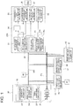
- FIG. 1 is a block diagram illustrating a display device for an electric vehicle according to the present embodiment.
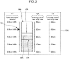
- FIG. 2 and FIG. 3 are each a diagram illustrating a display example in a display unit of the display device for the electric vehicle illustrated in FIG. 1 .
- FIG. 2 illustrates a display example corresponding to a state where an air conditioner is used.
- FIG. 3 illustrates a display example corresponding to a state where the air conditioner is unused.
- An electric car (hereinafter, referred to as a vehicle), illustrated in FIG. 1 , is provided with the display device for the electric vehicle according to the present embodiment, and includes: a display unit 10A; a calculation unit 20A; a battery pack 30 including a traction battery 31; a traction motor 41 which receives power supply from the traction battery 31 through a power cable PC; an electric compressor 42; an electric water heater 43; an accessory battery (not illustrated) which supplies power to accessories of the vehicle; a speed meter 48; and the like.
- the display unit 10A may be provided as an independent display device (such as a liquid crystal panel for example) on an instrument panel, or may be provided by a navigation system as a display screen.
- the calculation unit 20A may be implemented with an independent calculation device with a dedicated electronics control unit (ECU) additionally provided, or may be implemented with a program added to a built-in ECU.
- ECU dedicated electronics control unit
- electrical equipment other than the traction motor 41 or the accessory battery, which receives power supply from the traction battery 31 includes an air conditioner including the electric compressor 42 and the electric water heater 43. Power consumption and power consumption rate, described later, are calculated on the basis of whether the air conditioner including these components is used or unused. Alternatively, the calculation may be based on whether any one of the electric compressor 42 and the electric water heater 43 is used or unused.
- the calculation for the power consumption and the power consumption rate, described later may be further based on whether the other electrical equipment is used or unused. Examples of such additional electrical equipment include a seat heater and a headlamp.
- the display on the display unit 10A includes: a power consumption rate scale 11; a remaining possible travel range scale 12A; a full-charge possible travel range scale 13; and a display area 14A as illustrated in FIG. 2 and FIG. 3 .
- An instantaneous value line 15A, an air conditioner unused state average value line 16A, and an air conditioner used state average value line 17A, as line portions, are displayed in the display area 14A.
- a catalog power consumption rate mark 18 is displayed in the power consumption rate scale 11.
- the display area 14A is a rectangle area between the power consumption rate scale 11 and the remaining possible travel range scale 12A.
- the air conditioner unused state indicates this state
- the air conditioner used condition indicates a state that assumes a case where the air conditioner is unused.
- the air conditioner used state indicates this state
- the air conditioner used state indicates a state that assumes a case where the air conditioner is used.
- the power consumption rate scale 11 has vertical scales of power consumption rate for the instantaneous value line 15A, the average value line 16A, and the average value line 17A, in the unit of "km/kWh".
- fixed scale values incremented in a unit of 2.0 km/kWh with the maximum value being 8.0 km/kWh are employed.
- the scale values may be appropriately set differently among vehicle models, vehicles, and the like.
- the remaining possible travel range scale 12A also has vertical scales of the possible travel range for the instantaneous value line 15A, the average value line 16A, and the average value line 17A, in a unit of "km". As will be described in detail later, the instantaneous value line 15A, the average value line 16A, and the average value line 17A each indicate the power consumption rate and the possible travel range.
- the instantaneous value line 15A, the average value line 16A, and the average value line 17A are each a straight line (horizontal line) extending in a horizontal direction.
- the scale value of the remaining possible travel range scale 12A is a variable value that changes as appropriate on the basis of a remaining battery capacity level 33a and a battery capacity deterioration 34a (remaining amount) of the traction battery 31.
- the scale value is incremented in a unit of 10 km with the maximum value being 40 km.
- the scale values are the same as those of the full-charge possible travel range scale 13 when the traction battery 31 is fully charged and there is no battery capacity deterioration, that is, when the traction battery 31 has the remaining amount equal to the initial battery capacity.
- the power consumption rate scale 11 and the remaining possible travel range scale 12A are associated with each other and are arranged side by side in the horizontal direction while extending in parallel with each other, on both sides (left and right sides in the figure) of the instantaneous value line 15A, the average value line 16A, and the average value line 17A displayed as horizontal lines.
- the power consumption rate scale 11 and the remaining possible travel range scale 12A may have horizontal scales, may be associated with each other, and may be arranged side by side in the vertical direction (upper and lower sides in the figure) while extending in parallel with each other.
- the instantaneous value line 15A, the average value line 16A, and the average value line 17A may each be provided between the scales, as a vertical line shifting in a lateral direction.
- the display mode illustrated in FIG. 2 and FIG. 3 may be changed by being rotated by 90°.
- the power consumption rate scale 11 and the remaining possible travel range scale 12A may be modified to have circular or arc shaped scales.
- the power consumption rate scale 11 and the remaining possible travel range scale 12A having the circular or arc shaped scales may be concentrically arranged and may be associated with each other with the one of the scales provided more on the inner side than the other.
- the instantaneous value line 15A, the average value line 16A, and the average value line 17A may each be displayed as a line (a straight line or a curved line) shifting in a circumference direction of the scales having the circular or arc shape.
- the full-charge possible travel range scale 13 is displayed side by side with the remaining possible travel range scale 12A, and has a vertical scale indicating a possible travel range in the unit of "km" as in the case of the scale described above.
- the scale has fixed values incremented in a unit of 20 km, with the maximum value being 80 km.
- the scale values may be appropriately set to be different among vehicle models, vehicles, and the like.
- the full-charge possible travel range scale 13 may be omitted from the display.
- the instantaneous value line 15A which is a horizontal line, has an end portion that is closer to the power consumption rate scale 11 and indicates instantaneous power consumption rate (first power consumption rate) calculated by an instantaneous power consumption rate calculation unit 25 described later, and has an end portion that is closer to the remaining possible travel range scale 12A and indicates the possible travel range (first possible travel range) achievable at the instantaneous power consumption rate.
- the instantaneous value line 15A has a displayed position in the display area 14A shifting in the vertical direction based on the instantaneous power consumption rate calculated.
- the average value line 16A which is a horizontal line, has an end portion that is closer to the power consumption rate scale 11 and indicates average power consumption rate (second power consumption rate) in the air conditioner unused state calculated by an air conditioner unused state average power consumption rate calculation unit 26 described later, and has an end portion that is closer to the remaining possible travel range scale 12A and indicates the possible travel range (second possible travel range) achievable at the average power consumption rate in the air conditioner unused state.
- the average value line 16A has a displayed position in the display area 14A shifting in the vertical direction based on the average power consumption rate in the air conditioner unused state calculated.
- the average value line 16A is displayed as a part of a displayed bar graph.
- the average value line 17A as a horizontal line, has an end portion that is closer to the power consumption rate scale 11 and indicates average power consumption rate (third power consumption rate) in the air conditioner used state calculated by an air conditioner used state average power consumption rate calculation unit 27 described later, and has an end portion that is closer to the remaining possible travel range scale 12A and indicates the possible travel range (third possible travel range) achievable at the average power consumption rate in the air conditioner used state.
- the average value line 17A has a displayed position in the display area 14A shifting in the vertical direction based on the average power consumption rate in the air conditioner used state calculated.
- the average value line 17A is displayed as a part of the displayed bar graph.
- the average power consumption rate in the air conditioner unused state is calculated, and the air conditioner unused state average value line 16A is displayed together with the air conditioner used state average value line 17A and the instantaneous value line 15A as illustrated in FIG. 2 .
- the average power consumption rate in the air conditioner used state is calculated (estimated value calculation), and the air conditioner used state average value line 17A is displayed together with the air conditioner unused state average value line 16A and the instantaneous value line 15A as illustrated in FIG. 3 .
- the air conditioner used state average value line 17A and the air conditioner unused state average value line 16A are displayed visually differently, with the former being more noticeable than the latter.
- the two lines are different types of lines, or have different colors or densities.
- An area from the origin to the air conditioner used state average value line 17A and an area from the air conditioner used state average value line 17A to the air conditioner unused state average value line 16A are displayed visually differently, with the former being more noticeable than the latter.
- the two areas have different colors, densities, or lighting states (see FIG. 2 ).
- the air conditioner unused state average value line 16A and the air conditioner used state average value line 17A are displayed visually differently, with the former being more noticeable than the latter.
- the two lines are different types of lines, or have different colors or densities.
- the area from the air conditioner used state average value line 17A to the air conditioner unused state average value line 16A and the area from the origin to the air conditioner used state average value line 17A are displayed visually differently, with the former being more noticeable than the latter.
- the two areas have different colors, densities, or lighting states (see FIG. 3 ).
- two lines may be displayed with: one of the two lines displayed to be more noticeable being a solid line whereas the other one being a dotted line; the one displayed to be more noticeable having a more noticeable color whereas the other one having a different and less noticeable color; and the one displayed to be more noticeable in a color having a high density whereas the other one in a color having a low density.
- Two areas may be displayed with: one of the areas displayed to be more noticeable having a more noticeable color whereas the other one having a different and less noticeable color; the one displayed to be more noticeable in a color having a high density whereas the other one in a color having a low density; and the one displayed to be more noticeable being in a lighting state, whereas the other one being in a blinking state.
- the instantaneous value line 15A may be displayed visually differently from the average value line 16A and the average value line 17A.
- the instantaneous value line 15A may be a different type of line, or have a different color or density compared with the average value line 16A and the average value line 17A.
- the catalog power consumption rate mark 18 indicates a catalog power consumption rate (target value) of the vehicle, and is displayed for the comparison with the instantaneous value line 15A, the average value line 16A, and the average value line 17A.
- the catalog power consumption rate is indicated with a triangular mark in the power consumption rate scale 11.
- the mark may also be displayed in the display area 14A.
- the mark may have other shapes, examples of which include an arrow shape and a line.
- the present invention is not limited to this example where the catalog power consumption rate is displayed, and any index for the driver, such as information on the ecological driving, may be displayed.
- the instantaneous value line 15A, the average value line 16A, and the average value line 17A each indicate a power consumption rate and a possible travel range.
- the driver can be view a display with which the association between the power consumption rate and the possible travel range can be recognized.
- the catalog power consumption rate indicated by the catalog power consumption rate mark 18 is displayed to the driver together with the power consumption rate and the possible travel range indicated by the instantaneous value line 15A, the average value line 16A, and the average value line 17A.
- the driver can be guided towards the ecological driving involving a power consumption rate close to the catalog power consumption rate, whereby the possible travel range can be prevented from decreasing.
- the display on the display unit 10A illustrated in FIG. 2 and FIG. 3 is based on the calculation by the calculation unit 20A. First of all, configurations of the battery pack 30, the traction motor 41, the electric compressor 42, the electric water heater 43, and the speed meter 48 are described, as the basis for describing the configuration and the calculation of the calculation unit 20A, with reference to FIG. 1 .
- the battery pack 30 includes: the traction battery 31; and a battery management unit (BMU) 32 that measures various statuses of the traction battery 31 and performs calculation for controlling the traction battery 31.
- the BMU 32 is provided with a remaining battery capacity level calculation unit 33, a battery capacity deterioration calculation unit 34, a battery current/voltage measurement unit 35, and the like.
- the remaining battery capacity level calculation unit 33 calculates the remaining battery capacity level (SOC: State of Charge) 33a of the traction battery 31.
- the battery capacity deterioration calculation unit 34 calculates the battery capacity deterioration (SOH: State of Health) 34a of the traction battery 31.
- the battery current/voltage measurement unit 35 measures current and voltage of the traction battery 31.
- the remaining battery capacity level calculation unit 33 and the battery capacity deterioration calculation unit 34 employ known methods to respectively calculate the remaining battery capacity level 33a and the battery capacity deterioration 34a.
- a motor control unit (MCU) 44 controls power supply from the traction battery 31 to the traction motor 41 through the power cable PC.
- An MCU power consumption calculation unit 45 provided to the MCU 44, calculates the power consumption of the traction motor 41.
- an electric compressor power consumption calculation unit 46 provided to the electric compressor 42, calculates the power consumption of the electric compressor 42.
- an electric water heater power consumption calculation unit 47 provided to the electric water heater 43, calculates the power consumption of the electric water heater 43.
- the power consumption of the accessory battery is calculated by a similar configuration.
- the speed meter 48 which is a meter displaying vehicle speed, calculates the rotation speed of the wheels based the rotation speed of the traction motor 41 calculated by the MCU 44 to calculate the vehicle speed, and displays the vehicle speed calculated.
- the display unit 10A, the calculation unit 20A, the BMU 32, the electric compressor 42, the electric water heater 43, the MCU 44, the accessory battery, and the speed meter 48 are connected to each other in such a manner as to be capable of communicating with each other to exchange information, through a network NW examples of which include a controller area network (CAN).
- the calculation unit 20A receives information from the BMU 32, the electric compressor 42, the electric water heater 43, the MCU 44, the accessory battery, and the speed meter 48, and calculates the power consumption rate or the like based on the information. The result of the calculation is displayed on the display unit 10A.
- the calculation unit 20A includes an air conditioner unused state power calculation unit 21, an air conditioner used state power calculation unit 22, a vehicle speed calculation unit 23, a selection unit 24, the instantaneous power consumption rate calculation unit 25, the air conditioner unused state average power consumption rate calculation unit 26, the air conditioner used state average power consumption rate calculation unit 27, and a remaining possible travel range scale calculation unit 28.
- the air conditioner unused state power calculation unit 21 calculates the power consumption of the traction battery 31 in the air conditioner unused state. Specifically, in the air conditioner unused condition where the air conditioner is unused, the air conditioner unused state power calculation unit 21 calculates the power consumption in the air conditioner unused state based on the battery current and the battery voltage measured by the battery current/voltage measurement unit 35, or calculates the power consumption of the traction motor 41 and the power consumption of the accessory battery calculated by the MCU power consumption calculation unit 45, as the power consumption in the air conditioner unused state.
- the air conditioner unused state power calculation unit 21 calculates the power consumption in the air conditioner unused state by subtracting the power consumption calculated based on the battery current and the battery voltage of the traction battery 31 measured by the battery current/voltage measurement unit 35, by the power consumption of the electric compressor 42 calculated by the electric compressor power consumption calculation unit 46 and the power consumption of the electric water heater 43 calculated by the electric water heater power consumption calculation unit 47.
- the air conditioner unused state power calculation unit 21 calculates the power consumption in the air conditioner unused state as the power consumption of the traction motor 41 and the power consumption of the accessory battery calculated by the MCU power consumption calculation unit 45.
- the air conditioner unused state power calculation unit 21 calculates the power consumption of the traction motor 41 and the accessory battery as the power consumption in the air conditioner unused state.
- the power consumption in the air conditioner unused state calculated by the air conditioner unused state power calculation unit 21 is input to the selection unit 24 and the air conditioner unused state average power consumption rate calculation unit 26.
- the air conditioner unused state power calculation unit 21 is in a hybrid vehicle, the calculation is performed if the vehicle is in an EV driving mode.
- the air conditioner used state power calculation unit 22 calculates the power consumption of the traction battery 31 in the air conditioner used state. Specifically, in the air conditioner used condition where the air conditioner is used, the air conditioner used state power calculation unit 22 calculates the power consumption in the air conditioner used state based on the battery current and the battery voltage of the traction battery 31 measured by the battery current/voltage measurement unit 35, or as a sum of the power consumption of the traction motor 41 and the power consumption of the accessory battery calculated by the MCU power consumption calculation unit 45, the power consumption of the electric compressor 42 calculated by the electric compressor power consumption calculation unit 46, and the power consumption of the electric water heater 43 calculated by the electric water heater power consumption calculation unit 47.
- the estimation value described above may be obtained as the power consumption estimated from the current temperature inside and outside the vehicle, based on pre-set map data (map data indicating the relationship between the temperature inside and outside the vehicle and the power consumption).
- the air conditioner used state power calculation unit 22 may calculate the power consumption in the air conditioner used state by adding the estimated values of the power consumption estimated by the electric compressor power consumption calculation unit 46 and the electric water heater power consumption calculation unit 47 to the power consumption calculated based on the battery current and the battery voltage of the traction battery 31 measured by the battery current/voltage measurement unit 35 or to the power consumption of the traction motor 41 and the power consumption of the accessory battery calculated by the MCU power consumption calculation unit 45.
- the air conditioner used state power calculation unit 22 calculates the power consumption in the air conditioner used state as the actual power consumption or the estimated power consumption of the traction motor 41, the accessory battery, the electric compressor 42, and the electric water heater 43.
- the power consumption in the air conditioner used state calculated by the air conditioner used state power calculation unit 22 is input to the selection unit 24 and the air conditioner used state average power consumption rate calculation unit 27.
- this calculation is also performed while the vehicle is in the EV driving mode.
- the vehicle speed calculation unit 23 acquires the vehicle speed displayed on the speed meter 48 or calculates the vehicle speed based on the rotation speed of the traction motor 41 measured by the MCU 44.
- the vehicle speed thus acquired or calculated is input to the instantaneous power consumption rate calculation unit 25, the air conditioner unused state average power consumption rate calculation unit 26, and the air conditioner used state average power consumption rate calculation unit 27.
- the instantaneous power consumption rate calculation unit 25 calculates the instantaneous power consumption rate based on the vehicle speed received from the vehicle speed calculation unit 23 and the power consumption received from the selection unit 24. Specifically, the instantaneous travel distance at the current moment (a predetermined period of time which is several to several hundreds of milliseconds) is calculated based on the vehicle speed received from the vehicle speed calculation unit 23, the instantaneous power consumption at the moment (instantaneous travel distance) is calculated based on the power consumption received from the selection unit 24, and the instantaneous power consumption rate is obtained by dividing the instantaneous travel distance thus calculated by the instantaneous power consumption thus calculated. The instantaneous power consumption rate thus obtained is input to the display unit 10A, to be displayed as the instantaneous value line 15A illustrated in FIG. 2 and FIG. 3 .
- the air conditioner unused state average power consumption rate calculation unit 26 calculates the average power consumption rate in the air conditioner unused state based on the vehicle speed received from the vehicle speed calculation unit 23 and the power consumption in the air conditioner unused state received from the air conditioner unused state power calculation unit 21. Specifically, a travelling time corresponding to the predetermined travel distance (predetermined distance of several to several tens of kilometers) set in advance is calculated based on the vehicle speed received from the vehicle speed calculation unit 23. Then, the power consumption in the air conditioner unused state, received from the air conditioner unused state power calculation unit 21, is integrated within the calculated travelling time (predetermined travel distance). The predetermined travel distance is divided by the integrated power consumption, whereby the average power consumption rate in the air conditioner unused state is obtained.
- predetermined travel distance predetermined distance of several to several tens of kilometers
- the power consumption rate in the air conditioner unused state is calculated for a plurality of times, while the vehicle travels for the predetermined travel distance, and then the power consumption rates calculated for a plurality of times are averaged, whereby the average power consumption rate is obtained.
- the average power consumption rate thus obtained is input to the display unit 10A, and is displayed as the average value line 16A illustrated in FIG. 2 and FIG. 3 .
- the "predetermined travel distance" is longer than the instantaneous travel distance described above.
- the air conditioner used state average power consumption rate calculation unit 27 calculates the average power consumption rate in the air conditioner used state, based on the vehicle speed received from the vehicle speed calculation unit 23 and the power consumption in the air conditioner used state received from the air conditioner used state power calculation unit 22. Specifically, the travelling time corresponding to the predetermined travel distance described above is calculated based on the vehicle speed received from the vehicle speed calculation unit 23. Then, the power consumption in the air conditioner used state, received from the air conditioner used state power calculation unit 22, is integrated within the calculated travelling time (predetermined travel distance). The predetermined travel distance is divided by the integrated power consumption, whereby the average power consumption rate in the air conditioner used state is obtained.
- the power consumption rate in the air conditioner used state is calculated for a plurality of times, while the vehicle travels for the predetermined travel distance, and then the power consumption rates calculated for a plurality of times are averaged, whereby the average power consumption rate is obtained.
- the average power consumption rate thus obtained is input to the display unit 10A, and is displayed as the average value line 17A illustrated in FIG. 2 and FIG. 3 .
- the remaining possible travel range scale calculation unit 28 calculates a scale value of the remaining possible travel range scale 12A, based on the remaining battery capacity level 33a acquired from the remaining battery capacity level calculation unit 33 and the battery capacity deterioration 34a acquired from the battery capacity deterioration calculation unit 34 (based on the remaining amount).
- the scale value thus calculated is input to the display unit 10A, to be displayed as the remaining possible travel range scale 12A illustrated in FIG. 2 and FIG. 3 .
- the battery capacity deterioration 34a usually never changes dramatically, as long as there is no abnormality in the traction battery 31.
- the scale value indicated by the remaining possible travel range scale 12A usually change in proportion to the remaining battery capacity level 33a.
- the remaining possible travel range scale calculation unit 28 which is technically in charge of calculating the scale value of the remaining possible travel range scale 12A, actually calculates the possible travel range corresponding to each power consumption rate, on the basis the remaining battery capacity level 33a and the battery capacity deterioration 34a (the remaining amount), and on the basis of the power consumption rate indicated by the lines including the instantaneous value line 15A, the average value line 16A, and the average value line 17A.
- the scale value of the remaining possible travel range scale 12A changes frequently.
- the scale value may be hidden, or the instantaneous value line 15A, the average value line 16A and the average value line 17A may entirely be hidden.
- the scale value of the remaining possible travel range scale 12A may be hidden, or the instantaneous value line 15A, the average value line 16A, and the average value line 17A may entirely be hidden, when the SOC (%) drops to or below 40%.
- the instantaneous value line 15A, the average value line 16A, and the average value line 17A are displayed on the display unit 10A, as a result of the calculation performed by the calculation unit 20A as described above.
- the relationship between the power consumption rate and the possible travel range can be indicated with the instantaneous value line 15A, the average value line 16A, and the average value line 17A.
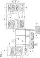
- FIG. 4 is a block diagram illustrating a display device for an electric vehicle according to the present embodiment.
- FIG. 5 and FIG. 6 each illustrate a display example of a display unit of the display device for the electric vehicle illustrated in FIG. 4 .
- FIG. 5 illustrates a display example in a state where the air conditioner is used (air conditioner used condition)
- FIG. 6 illustrates a display example in a state where the air conditioner is unused (air conditioner unused condition).
- the display device for the electric vehicle according to the present embodiment has a configuration substantially the same as that of the display device for the electric vehicle described in Embodiment 1 (see FIG. 1 to FIG. 3 and the like), except for part of the configuration.
- the different configuration is mainly described below, and redundant description is omitted.
- a vehicle including the display device for the electric vehicle according to the present embodiment includes a display unit 10B, a calculation unit 20B, and the like, and has the same configuration as that in Embodiment 1 (see FIG. 1 and the like) except for the configurations of the display unit 10B and the calculation unit 20B.
- the display unit 10B may be provided as an independent display device on an instrument panel, or may be provided by a navigation system as a display screen.
- the calculation unit 20B may be implemented with an independent calculation device with a dedicated ECU additionally provided, or may be implemented with a program added to a built-in ECU.
- the remaining possible travel range scale 12B is for displaying a vertical scale for the possible travel range corresponding to the instantaneous value line 15B, the average value line 16B, and the average value line 17B, in the unit of "km".
- the instantaneous value line 15B, the average value line 16B, and the average value line 17B indicate the power consumption rate and the possible travel range.
- the remaining possible travel range scale 12B in the display unit 10B according to the present embodiment has a fixed scale value.
- the fixed scale value is incremented in a unit of 20 km with the maximum value being 80 km.
- the display unit 10B according to the present embodiment includes the power consumption rate scale 11 and the remaining possible travel range scale 12B with fixed scale values.
- the scale values may be appropriately set differently among vehicle models, vehicles, and the like.
- the scale values of the power consumption rate scale 11 and the remaining possible travel range scale 12B are set in such a manner that instantaneous value line 15B, the average value line 16B, and the average value line 17B are displayed as horizontal lines, when the traction battery 31 is fully charged and there is no battery capacity deterioration (when the traction battery 31 has the remaining amount equal to the initial battery capacity).
- the instantaneous value line 15B, the average value line 16B, and the average value line 17B are displayed as oblique lines when the remaining amount of the traction battery 31 is below the initial battery capacity as illustrated in FIG. 5 and FIG. 6 .
- the battery capacity deterioration 34a usually never changes dramatically.
- the oblique lines have an inclined angle usually changing in proportion to the remaining battery capacity level 33a.
- the instantaneous value line 15B, the average value line 16B, and the average value line 17B usually shift in the vertical direction and have inclined angles changing in accordance with the remaining battery capacity level 33a.
- the power consumption rate scale 11 and the remaining possible travel range scale 12B having vertical scales are associated with each other, and are arranged side by side in the horizontal direction while extending in parallel with each other, on both sides (left and right sides in the figure) of the instantaneous value line 15B, the average value line 16B, and the average value line 17B displayed as oblique lines (or horizontal lines).
- the power consumption rate scale 11 and the remaining possible travel range scale 12B may having horizontal scales, may be associated with each other, and may be arranged side by side in the vertical direction (upper and lower sides in the figure) while extending in parallel with each other.
- the instantaneous value line 15B, the average value line 16B, and the average value line 17B may each be provided between the scales as oblique lines shifting in the lateral direction and having the inclined angle changed.
- the display mode illustrated in FIG. 5 and FIG. 6 may be changed by being rotated by 90°.
- the power consumption rate scale 11 and the remaining possible travel range scale 12B may be modified to have circular or arc shaped scales.
- the power consumption rate scale 11 and the remaining possible travel range scale 12B having the circular or arc shaped scales may be concentrically arranged and may be associated with each other with the one of the scales provided more on the inner side than the other.
- the instantaneous value line 15B, the average value line 16B, and the average value line 17B may be each displayed as a line (a straight line or a curved line) shifting in the circumference direction of the scales having the circular or arc shape.
- the instantaneous value line 15B as an oblique line (horizontal line), has an end portion that is closer to the power consumption rate scale 11 and indicates the instantaneous power consumption rate (first power consumption rate) calculated by the instantaneous power consumption rate calculation unit 25, and has an end portion that is closer to the remaining possible travel range scale 12B and indicates the possible travel range (first possible travel range) achievable at the instantaneous power consumption rate.
- the instantaneous value line 15B has a displayed position in the display area 14B shifting in the vertical direction based on the instantaneous power consumption rate calculated and having an inclined angle changing in accordance with calculation by a line portion inclination angle calculation unit 29 described later.
- the average value line 16B as an oblique line (horizontal line), has an end portion that is closer to the power consumption rate scale 11 and indicates the average power consumption rate (second power consumption rate) in the air conditioner unused state calculated by the air conditioner unused state average power consumption rate calculation unit 26, and has an end portion that is closer to the remaining possible travel range scale 12B and indicates the possible travel range (second possible travel range) achievable at the average power consumption rate in the air conditioner unused state.
- the average value line 16B has a displayed position in the display area 14B shifting in the vertical direction based on the average power consumption rate in the air conditioner unused state calculated and having an inclined angle changing in accordance with calculation by the line portion inclination angle calculation unit 29 described later.
- the average value line 16B is displayed as a part of a displayed bar graph.
- the average value line 17B as an oblique line (horizontal line), has an end portion that is closer to the power consumption rate scale 11 and indicates the average power consumption rate (third power consumption rate) in the air conditioner used state calculated by the air conditioner used state average power consumption rate calculation unit 27, and has an end portion that is closer to the remaining possible travel range scale 12B and indicates the possible travel range (third possible travel range) achievable at the average power consumption rate in the air conditioner used state.
- the average value line 17B has a displayed position in the display area 14B shifting in the vertical direction based on the average power consumption rate in the air conditioner used state calculated and having an inclined angle changing in accordance with calculation by the line portion inclination angle calculation unit 29 described later.
- the average value line 17B is displayed as a part of the displayed bar graph.
- the average power consumption rate in the air conditioner unused state is calculated, and the air conditioner unused state average value line 16B is displayed together with the air conditioner used state average value line 17B and the instantaneous value line 15B as illustrated in FIG. 5 .
- the average power consumption rate in the air conditioner used state is calculated (estimated value calculation), and the air conditioner used state average value line 17B is displayed together with the air conditioner unused state average value line 16B and the instantaneous value line 15B as illustrated in FIG. 6 .
- the air conditioner used state average value line 17B and the air conditioner unused state average value line 16B are displayed visually differently, with the former being more noticeable than the latter.
- the two lines are different types of lines, or have different colors or densities.
- An area from the origin to the air conditioner used state average value line 17B and an area from the air conditioner used state average value line 17B to the air conditioner unused state average value line 16B are displayed visually differently, with the former being more noticeable than the latter.
- the two areas have different colors, densities, or lighting states (see FIG. 5 ).
- the air conditioner unused state average value line 16B and the air conditioner used state average value line 17B are displayed visually differently, with the former being more noticeable than the latter.
- the two lines are different types of lines, or have different colors or densities.
- the area from the air conditioner used state average value line 17B to the air conditioner unused state average value line 16B and the area from the origin to the air conditioner used state average value line 17B are displayed visually differently, with the former being more noticeable than the latter.
- the two areas have different colors, densities, or lighting states (see FIG. 6 ).
- the air conditioner unused state average value line 16B and the air conditioner used state average value line 17B may be displayed visually differently, with the former being more noticeable than the latter. With such a display mode, the driver can more easily notice the air conditioner unused state average value line 16B, and thus can be guided towards the ecological driving.
- the instantaneous value line 15B may be displayed visually differently from the average value line 16B and the average value line 17B.
- the instantaneous value line 15B may be a different type of line, or have a different color or density compared with the average value line 16B and the average value line 17B.
- the instantaneous value line 15B, the average value line 16B, and the average value line 17B each indicate the power consumption rate and the possible travel range.
- the driver can be provided with a display with which an association between the power consumption rate and the possible travel range can be recognized.
- the catalog power consumption rate indicated by the catalog power consumption rate mark 18 is displayed to the driver together with the power consumption rate and the possible travel range indicated by the instantaneous value line 15B, the average value line 16B, and the average value line 17B.
- the driver can be guided towards the ecological driving involving a power consumption rate close to the catalog power consumption rate, whereby the possible travel range can be prevented from decreasing.
- the display on the display unit 10B illustrated in FIG. 5 and FIG. 6 is based on the calculation by the calculation unit 20B. More specifically, as in Embodiment 1, the calculation unit 20B receives information from the BMU 32, the electric compressor 42, the electric water heater 43, the MCU 44, the accessory battery, and the speed meter 48, and calculates the power consumption rate or the like based on the information. The result of the calculation is displayed on the display unit 10B.
- the calculation unit 20B includes the air conditioner unused state power calculation unit 21, the air conditioner used state power calculation unit 22, the vehicle speed calculation unit 23, the selection unit 24, the instantaneous power consumption rate calculation unit 25, the air conditioner unused state average power consumption rate calculation unit 26, and the air conditioner used state average power consumption rate calculation unit 27, as in the case of the calculation unit 20A (refer to FIG. 1 and the like) in Embodiment 1.
- the calculation unit 20B according to the present embodiment includes the line portion inclination angle calculation unit 29, instead of the remaining possible travel range scale calculation unit 28 in the calculation unit 20A according to Embodiment 1.
- the line portion inclination angle calculation unit 29 calculates a scale value that is similar to the scale value of the remaining possible travel range scale 12A, based on the remaining battery capacity level 33a acquired from the remaining battery capacity level calculation unit 33 and the battery capacity deterioration 34a acquired from the battery capacity deterioration calculation unit 34 (based on the remaining amount), as in the case of the remaining possible travel range scale calculation unit 28.
- the remaining possible travel range scale 12B according to the present embodiment has fixed scale values.
- the inclined angles of the instantaneous value line 15B, the average value line 16B, and the average value line 17B are each calculated based on the amount or rate of change between the calculated scale value and the fixed scale value.
- the line portion inclination angle calculation unit 29, which is technically in charge of calculating the inclination angles of the instantaneous value line 15B, the average value line 16B, and the average value line 17B, actually calculates the possible travel range corresponding to the power consumption rate indicated by the instantaneous value line 15B, the average value line 16B, and the average value line 17B, based on the remaining battery capacity level 33a and the battery capacity deterioration 34a (the remaining amount).
- a calculation unit that directly calculates the possible travel range may be provided.
- the possible travel range achievable at the instantaneous power consumption rate, the possible travel range achievable at the air conditioner unused state average power consumption rate, and the possible travel range achievable at the air conditioner used state average power consumption rate may be calculated for the instantaneous power consumption rate calculated by the instantaneous power consumption rate calculation unit 25, the air conditioner unused state average power consumption rate calculated by air conditioner unused state average power consumption rate calculation unit 26, and the air conditioner used state average power consumption rate calculated by the air conditioner used state average power consumption rate calculation unit 27.
- the display unit 10B receives the inclination angle calculated by the line portion inclination angle calculation unit 29, as well as the instantaneous power consumption rate calculated by the instantaneous power consumption rate calculation unit 25, the air conditioner unused state average power consumption rate calculated by the air conditioner unused state average power consumption rate calculation unit 26, and the air conditioner used state average power consumption rate calculated by the air conditioner used state average power consumption rate calculation unit 27.
- the instantaneous value line 15B displayed by the display unit 10B has the end portion that is closer to the power consumption rate scale 11 and indicates the instantaneous power consumption rate and the end portion that is closer to the remaining possible travel range scale 12B and indicates the possible travel range achievable at the instantaneous power consumption rate.
- the average value line 16B displayed has the end portion that is closer to the power consumption rate scale 11 and indicates the average power consumption rate in the air conditioner unused state and the end portion that is closer to the remaining possible travel range scale 12B and indicates the possible travel range achievable at the average power consumption rate in the air conditioner unused state.
- the average value line 17B displayed has the end portion that is closer to the power consumption rate scale 11 and indicates the average power consumption rate in the air conditioner used state and the end portion that is closer to the remaining possible travel range scale 12B and indicates the possible travel range achievable at the average power consumption rate in the air conditioner used state.
- the calculation unit 20B performs the calculation described above, and the instantaneous value line 15B, the average value line 16B, and the average value line 17B are displayed on the display unit 10B.
- the relationship between the power consumption rate and the possible travel range can be indicated with the instantaneous value line 15B, the average value line 16B, and the average value line 17B.
- the instantaneous power consumption rate, the average power consumption rate in the air conditioner unused state, and the average power consumption rate in the air conditioner used state are calculated on the basis of the power consumption of the traction battery 31.
- the calculation for the instantaneous power consumption rate, the average power consumption rate in the air conditioner unused state, and the average power consumption rate in the air conditioner used state may be further based on regenerative power provided by the generator.
- the power consumption rate (instantaneous power consumption rate, the average power consumption rate in the air conditioner unused state, and the average power consumption rate in the air conditioner used state) is defined by the power consumption rate (km/kWh) indicating the travel distance (km) achievable per unit of energy (1 kWh).
- a power consumption amount (kWh/km) indicating an energy amount (kWh) per unit travel distance (1 km) may be employed.
- the present application is suitably applied to electric vehicles such as electric cars and hybrid vehicles.
Landscapes
- Engineering & Computer Science (AREA)
- Transportation (AREA)
- Mechanical Engineering (AREA)
- Combustion & Propulsion (AREA)
- Chemical & Material Sciences (AREA)
- Physics & Mathematics (AREA)
- General Physics & Mathematics (AREA)
- Power Engineering (AREA)
- Sustainable Energy (AREA)
- Sustainable Development (AREA)
- Life Sciences & Earth Sciences (AREA)
- Automation & Control Theory (AREA)
- Electric Propulsion And Braking For Vehicles (AREA)
- Instrument Panels (AREA)
- Secondary Cells (AREA)
Abstract
Description
- This disclosure relates to a display device for an electric vehicle that displays a possible travel range and the like.
- Electric vehicles, such as electric cars for example, are provided with a driving range display device which displays a possible travel range achievable with a current remaining amount of a traction battery. For example, a driving range display apparatus in Patent Document 1 (Japanese Patent No.
5461365 FIG. 4 and the like). - Sales catalogs of electric cars introduce a catalog power consumption rate, which is a rate of power consumption (hereinafter, referred to as power consumption rate) indicating a travel distance (km) per unit energy amount (1 kWh). The catalog power consumption rate merely represents a power consumption rate obtained in a test drive of the electric car in a certain driving mode. However, the actual driving of the electric car by a driver involves a power consumption rate (hereinafter, referred to as an actual power consumption rate) may be affected by a driving operation by the driver (for example, operations for acceleration and air conditioner) to be lower than the catalog power consumption rate, resulting in a possible travel range smaller than expected. When information indicating the association between the possible travel range and the actual power consumption rate can be displayed to the driver, the driver can be guided to perform a driving operation (what is known as ecological driving) involving an actual power consumption rate close to the catalog power consumption rate.
- In view of the foregoing, an object of at least one embodiment of the present invention is to provide a display device for an electric vehicle that can perform displaying with which an association between the possible travel range and the power consumption rate can be recognized.
- A display device for the electric vehicle according to at least one embodiment of the present invention includes: a calculation unit which calculates a power consumption rate of the electric vehicle on the basis of a travel distance of the electric vehicle and power consumption of a traction battery of the electric vehicle relative to the travel distance; and a display unit which displays the power consumption rate calculated by the calculation unit, and a possible travel range achievable at the power consumption rate with a remaining amount of the traction battery. The display unit includes: a power consumption rate scale indicating scales of the power consumption rate; a possible travel range scale indicating scales of the possible travel range and disposed corresponding to the power consumption rate scale; and a line portion displayed between the power consumption rate scale and the possible travel range scale. The line portion has two end portions including an end portion that is closer to the power consumption rate scale and indicates the power consumption rate, and an end portion that is closer to the possible travel range scale and indicates the possible travel range.
- With the above-described configuration, the driver can be provided with a display with which an association between the possible travel range and the power consumption rate can be recognized. Thus, the driver can be guided towards ecological driving involving a power consumption rate close to a target value, whereby the possible travel range can be prevented from decreasing.
-
-
FIG. 1 is a block diagram of an electric vehicle according to one example (Embodiment 1) of the present invention; -
FIG. 2 is a diagram illustrating a display example in a display unit of a display device in the electric vehicle illustrated inFIG. 1 , is a state where an air conditioner is used; -
FIG. 3 is a diagram illustrating a display example in the display unit of the display device in the electric vehicle illustrated inFIG. 1 , is a state where the air conditioner is unused; -
FIG. 4 a block diagram of an electric vehicle according to one example (Embodiment 2) of the present invention; -
FIG. 5 is a diagram illustrating a display example in a display unit of a display device in the electric vehicle illustrated inFIG. 4 , is the state where the air conditioner is used; and -
FIG. 6 is a diagram illustrating a display example in the display unit of the display device in the electric vehicle illustrated inFIG. 4 , is the state where the air conditioner is unused. - A display device of an electric vehicle according to some embodiments of the present invention is described below with reference to
FIG. 1 to FIG. 6 . Examples of the electric vehicle include: an electric vehicle having a traction motor provided to one of front wheels and rear wheels as described herein; an electric vehicle having a traction motor provided to each of the front wheels and the rear wheels; and a hybrid vehicle (including a plug-in hybrid vehicle) having a traction motor provided to at least one of front wheels and rear wheels and also having an engine. When the electric vehicle is the hybrid vehicle, the present embodiment may be employed when the vehicle is driving under an Electric Vehicle (EV) driving mode using a traction battery and the traction motor. -
FIG. 1 is a block diagram illustrating a display device for an electric vehicle according to the present embodiment.FIG. 2 andFIG. 3 are each a diagram illustrating a display example in a display unit of the display device for the electric vehicle illustrated inFIG. 1 .FIG. 2 illustrates a display example corresponding to a state where an air conditioner is used.FIG. 3 illustrates a display example corresponding to a state where the air conditioner is unused. - An electric car (hereinafter, referred to as a vehicle), illustrated in
FIG. 1 , is provided with the display device for the electric vehicle according to the present embodiment, and includes: adisplay unit 10A; acalculation unit 20A; abattery pack 30 including atraction battery 31; atraction motor 41 which receives power supply from thetraction battery 31 through a power cable PC; anelectric compressor 42; anelectric water heater 43; an accessory battery (not illustrated) which supplies power to accessories of the vehicle; aspeed meter 48; and the like. - The
display unit 10A may be provided as an independent display device (such as a liquid crystal panel for example) on an instrument panel, or may be provided by a navigation system as a display screen. Thecalculation unit 20A may be implemented with an independent calculation device with a dedicated electronics control unit (ECU) additionally provided, or may be implemented with a program added to a built-in ECU. - In this example, electrical equipment, other than the
traction motor 41 or the accessory battery, which receives power supply from thetraction battery 31 includes an air conditioner including theelectric compressor 42 and theelectric water heater 43. Power consumption and power consumption rate, described later, are calculated on the basis of whether the air conditioner including these components is used or unused. Alternatively, the calculation may be based on whether any one of theelectric compressor 42 and theelectric water heater 43 is used or unused. When the vehicle further includes electrical equipment that receives power supply from thetraction battery 31, the calculation for the power consumption and the power consumption rate, described later, may be further based on whether the other electrical equipment is used or unused. Examples of such additional electrical equipment include a seat heater and a headlamp. - The display on the
display unit 10A, based on the calculation by thecalculation unit 20A described later, includes: a powerconsumption rate scale 11; a remaining possibletravel range scale 12A; a full-charge possibletravel range scale 13; and adisplay area 14A as illustrated inFIG. 2 andFIG. 3 . Aninstantaneous value line 15A, an air conditioner unused stateaverage value line 16A, and an air conditioner used stateaverage value line 17A, as line portions, are displayed in thedisplay area 14A. A catalog powerconsumption rate mark 18 is displayed in the powerconsumption rate scale 11. Thedisplay area 14A is a rectangle area between the powerconsumption rate scale 11 and the remaining possibletravel range scale 12A. - When the air conditioner is unused (hereinafter, referred to as an air conditioner unused condition), the "air conditioner unused state" indicates this state, whereas when the air conditioner is used (hereinafter, referred to as an air conditioner used condition), the "air conditioner unused state" indicates a state that assumes a case where the air conditioner is unused. In addition, when the air conditioner is used, the "air conditioner used state" indicates this state, whereas when the air conditioner is unused, the "air conditioner used state" indicates a state that assumes a case where the air conditioner is used.
- The power
consumption rate scale 11 has vertical scales of power consumption rate for theinstantaneous value line 15A, theaverage value line 16A, and theaverage value line 17A, in the unit of "km/kWh". In this example, fixed scale values incremented in a unit of 2.0 km/kWh with the maximum value being 8.0 km/kWh are employed. The scale values may be appropriately set differently among vehicle models, vehicles, and the like. - The remaining possible
travel range scale 12A also has vertical scales of the possible travel range for theinstantaneous value line 15A, theaverage value line 16A, and theaverage value line 17A, in a unit of "km". As will be described in detail later, theinstantaneous value line 15A, theaverage value line 16A, and theaverage value line 17A each indicate the power consumption rate and the possible travel range. - In the figure, the
instantaneous value line 15A, theaverage value line 16A, and theaverage value line 17A are each a straight line (horizontal line) extending in a horizontal direction. Thus, the scale value of the remaining possibletravel range scale 12A is a variable value that changes as appropriate on the basis of a remainingbattery capacity level 33a and abattery capacity deterioration 34a (remaining amount) of thetraction battery 31. In this example, the scale value is incremented in a unit of 10 km with the maximum value being 40 km. The scale values are the same as those of the full-charge possibletravel range scale 13 when thetraction battery 31 is fully charged and there is no battery capacity deterioration, that is, when thetraction battery 31 has the remaining amount equal to the initial battery capacity. - In
FIG. 2 andFIG. 3 , the powerconsumption rate scale 11 and the remaining possibletravel range scale 12A, having the vertical scales, are associated with each other and are arranged side by side in the horizontal direction while extending in parallel with each other, on both sides (left and right sides in the figure) of theinstantaneous value line 15A, theaverage value line 16A, and theaverage value line 17A displayed as horizontal lines. The powerconsumption rate scale 11 and the remaining possibletravel range scale 12A may have horizontal scales, may be associated with each other, and may be arranged side by side in the vertical direction (upper and lower sides in the figure) while extending in parallel with each other. In such a configuration, theinstantaneous value line 15A, theaverage value line 16A, and theaverage value line 17A may each be provided between the scales, as a vertical line shifting in a lateral direction. Simply put, the display mode illustrated inFIG. 2 andFIG. 3 may be changed by being rotated by 90°. The powerconsumption rate scale 11 and the remaining possibletravel range scale 12A may be modified to have circular or arc shaped scales. The powerconsumption rate scale 11 and the remaining possibletravel range scale 12A having the circular or arc shaped scales may be concentrically arranged and may be associated with each other with the one of the scales provided more on the inner side than the other. In such a configuration, theinstantaneous value line 15A, theaverage value line 16A, and theaverage value line 17A may each be displayed as a line (a straight line or a curved line) shifting in a circumference direction of the scales having the circular or arc shape. - The full-charge possible
travel range scale 13 is displayed side by side with the remaining possibletravel range scale 12A, and has a vertical scale indicating a possible travel range in the unit of "km" as in the case of the scale described above. In this example, the scale has fixed values incremented in a unit of 20 km, with the maximum value being 80 km. The scale values may be appropriately set to be different among vehicle models, vehicles, and the like. The full-charge possibletravel range scale 13 may be omitted from the display. - The
instantaneous value line 15A, which is a horizontal line, has an end portion that is closer to the powerconsumption rate scale 11 and indicates instantaneous power consumption rate (first power consumption rate) calculated by an instantaneous power consumptionrate calculation unit 25 described later, and has an end portion that is closer to the remaining possibletravel range scale 12A and indicates the possible travel range (first possible travel range) achievable at the instantaneous power consumption rate. Theinstantaneous value line 15A has a displayed position in thedisplay area 14A shifting in the vertical direction based on the instantaneous power consumption rate calculated. - The
average value line 16A, which is a horizontal line, has an end portion that is closer to the powerconsumption rate scale 11 and indicates average power consumption rate (second power consumption rate) in the air conditioner unused state calculated by an air conditioner unused state average power consumptionrate calculation unit 26 described later, and has an end portion that is closer to the remaining possibletravel range scale 12A and indicates the possible travel range (second possible travel range) achievable at the average power consumption rate in the air conditioner unused state. Theaverage value line 16A has a displayed position in thedisplay area 14A shifting in the vertical direction based on the average power consumption rate in the air conditioner unused state calculated. Theaverage value line 16A is displayed as a part of a displayed bar graph. - The
average value line 17A, as a horizontal line, has an end portion that is closer to the powerconsumption rate scale 11 and indicates average power consumption rate (third power consumption rate) in the air conditioner used state calculated by an air conditioner used state average power consumptionrate calculation unit 27 described later, and has an end portion that is closer to the remaining possibletravel range scale 12A and indicates the possible travel range (third possible travel range) achievable at the average power consumption rate in the air conditioner used state. Theaverage value line 17A has a displayed position in thedisplay area 14A shifting in the vertical direction based on the average power consumption rate in the air conditioner used state calculated. Theaverage value line 17A is displayed as a part of the displayed bar graph. - Even in the air conditioner used condition where the air conditioner is used, the average power consumption rate in the air conditioner unused state is calculated, and the air conditioner unused state
average value line 16A is displayed together with the air conditioner used stateaverage value line 17A and theinstantaneous value line 15A as illustrated inFIG. 2 . Even in the air conditioner unused condition where the air conditioner is unused, the average power consumption rate in the air conditioner used state is calculated (estimated value calculation), and the air conditioner used stateaverage value line 17A is displayed together with the air conditioner unused stateaverage value line 16A and theinstantaneous value line 15A as illustrated inFIG. 3 . - In the air conditioner used condition, the air conditioner used state
average value line 17A and the air conditioner unused stateaverage value line 16A are displayed visually differently, with the former being more noticeable than the latter. For example, the two lines are different types of lines, or have different colors or densities. An area from the origin to the air conditioner used stateaverage value line 17A and an area from the air conditioner used stateaverage value line 17A to the air conditioner unused stateaverage value line 16A are displayed visually differently, with the former being more noticeable than the latter. For example, the two areas have different colors, densities, or lighting states (seeFIG. 2 ). - Also in the air conditioner unused condition, the air conditioner unused state
average value line 16A and the air conditioner used stateaverage value line 17A are displayed visually differently, with the former being more noticeable than the latter. For example, the two lines are different types of lines, or have different colors or densities. The area from the air conditioner used stateaverage value line 17A to the air conditioner unused stateaverage value line 16A and the area from the origin to the air conditioner used stateaverage value line 17A are displayed visually differently, with the former being more noticeable than the latter. For example, the two areas have different colors, densities, or lighting states (seeFIG. 3 ). - For example, also in the air conditioner used condition, the air conditioner unused state
average value line 16A and the air conditioner used stateaverage value line 17A may be displayed visually differently, with the former being more noticeable than the latter. With such a display mode, the driver can more easily notice the air conditioner unused stateaverage value line 16A, and thus can be guided towards the ecological driving. - As alternative display examples, two lines (the
average value line 16A and theaverage value line 17A) may be displayed with: one of the two lines displayed to be more noticeable being a solid line whereas the other one being a dotted line; the one displayed to be more noticeable having a more noticeable color whereas the other one having a different and less noticeable color; and the one displayed to be more noticeable in a color having a high density whereas the other one in a color having a low density. Two areas (the area from the origin to theaverage value line 17A and the area from theaverage value line 17A to theaverage value line 16A) may be displayed with: one of the areas displayed to be more noticeable having a more noticeable color whereas the other one having a different and less noticeable color; the one displayed to be more noticeable in a color having a high density whereas the other one in a color having a low density; and the one displayed to be more noticeable being in a lighting state, whereas the other one being in a blinking state. - The
instantaneous value line 15A may be displayed visually differently from theaverage value line 16A and theaverage value line 17A. For example, theinstantaneous value line 15A may be a different type of line, or have a different color or density compared with theaverage value line 16A and theaverage value line 17A. - The catalog power
consumption rate mark 18 indicates a catalog power consumption rate (target value) of the vehicle, and is displayed for the comparison with theinstantaneous value line 15A, theaverage value line 16A, and theaverage value line 17A. In this example, the catalog power consumption rate is indicated with a triangular mark in the powerconsumption rate scale 11. The mark may also be displayed in thedisplay area 14A. The mark may have other shapes, examples of which include an arrow shape and a line. The present invention is not limited to this example where the catalog power consumption rate is displayed, and any index for the driver, such as information on the ecological driving, may be displayed. - In the
display unit 10A illustrated inFIG. 2 andFIG. 3 , theinstantaneous value line 15A, theaverage value line 16A, and theaverage value line 17A, as horizontal lines, each indicate a power consumption rate and a possible travel range. Thus, the driver can be view a display with which the association between the power consumption rate and the possible travel range can be recognized. The catalog power consumption rate indicated by the catalog powerconsumption rate mark 18 is displayed to the driver together with the power consumption rate and the possible travel range indicated by theinstantaneous value line 15A, theaverage value line 16A, and theaverage value line 17A. Thus, the driver can be guided towards the ecological driving involving a power consumption rate close to the catalog power consumption rate, whereby the possible travel range can be prevented from decreasing. - The display on the
display unit 10A illustrated inFIG. 2 andFIG. 3 is based on the calculation by thecalculation unit 20A. First of all, configurations of thebattery pack 30, thetraction motor 41, theelectric compressor 42, theelectric water heater 43, and thespeed meter 48 are described, as the basis for describing the configuration and the calculation of thecalculation unit 20A, with reference toFIG. 1 . - The
battery pack 30 includes: thetraction battery 31; and a battery management unit (BMU) 32 that measures various statuses of thetraction battery 31 and performs calculation for controlling thetraction battery 31. TheBMU 32 is provided with a remaining battery capacitylevel calculation unit 33, a battery capacitydeterioration calculation unit 34, a battery current/voltage measurement unit 35, and the like. The remaining battery capacitylevel calculation unit 33 calculates the remaining battery capacity level (SOC: State of Charge) 33a of thetraction battery 31. The battery capacitydeterioration calculation unit 34 calculates the battery capacity deterioration (SOH: State of Health) 34a of thetraction battery 31. The battery current/voltage measurement unit 35 measures current and voltage of thetraction battery 31. The remaining battery capacitylevel calculation unit 33 and the battery capacitydeterioration calculation unit 34 employ known methods to respectively calculate the remainingbattery capacity level 33a and thebattery capacity deterioration 34a. - A motor control unit (MCU) 44 controls power supply from the
traction battery 31 to thetraction motor 41 through the power cable PC. An MCU powerconsumption calculation unit 45, provided to theMCU 44, calculates the power consumption of thetraction motor 41. Similarly, an electric compressor powerconsumption calculation unit 46, provided to theelectric compressor 42, calculates the power consumption of theelectric compressor 42. Similarly, an electric water heater powerconsumption calculation unit 47, provided to theelectric water heater 43, calculates the power consumption of theelectric water heater 43. The power consumption of the accessory battery is calculated by a similar configuration. - For example, the
speed meter 48, which is a meter displaying vehicle speed, calculates the rotation speed of the wheels based the rotation speed of thetraction motor 41 calculated by theMCU 44 to calculate the vehicle speed, and displays the vehicle speed calculated. - The
display unit 10A, thecalculation unit 20A, theBMU 32, theelectric compressor 42, theelectric water heater 43, theMCU 44, the accessory battery, and thespeed meter 48 are connected to each other in such a manner as to be capable of communicating with each other to exchange information, through a network NW examples of which include a controller area network (CAN). Thecalculation unit 20A receives information from theBMU 32, theelectric compressor 42, theelectric water heater 43, theMCU 44, the accessory battery, and thespeed meter 48, and calculates the power consumption rate or the like based on the information. The result of the calculation is displayed on thedisplay unit 10A. - The
calculation unit 20A includes an air conditioner unused statepower calculation unit 21, an air conditioner used statepower calculation unit 22, a vehiclespeed calculation unit 23, aselection unit 24, the instantaneous power consumptionrate calculation unit 25, the air conditioner unused state average power consumptionrate calculation unit 26, the air conditioner used state average power consumptionrate calculation unit 27, and a remaining possible travel rangescale calculation unit 28. - The air conditioner unused state
power calculation unit 21 calculates the power consumption of thetraction battery 31 in the air conditioner unused state. Specifically, in the air conditioner unused condition where the air conditioner is unused, the air conditioner unused statepower calculation unit 21 calculates the power consumption in the air conditioner unused state based on the battery current and the battery voltage measured by the battery current/voltage measurement unit 35, or calculates the power consumption of thetraction motor 41 and the power consumption of the accessory battery calculated by the MCU powerconsumption calculation unit 45, as the power consumption in the air conditioner unused state. - In the air conditioner used condition where the air conditioner is used, the air conditioner unused state
power calculation unit 21 calculates the power consumption in the air conditioner unused state by subtracting the power consumption calculated based on the battery current and the battery voltage of thetraction battery 31 measured by the battery current/voltage measurement unit 35, by the power consumption of theelectric compressor 42 calculated by the electric compressor powerconsumption calculation unit 46 and the power consumption of theelectric water heater 43 calculated by the electric water heater powerconsumption calculation unit 47. Alternatively, the air conditioner unused statepower calculation unit 21 calculates the power consumption in the air conditioner unused state as the power consumption of thetraction motor 41 and the power consumption of the accessory battery calculated by the MCU powerconsumption calculation unit 45. - Thus, the air conditioner unused state
power calculation unit 21 calculates the power consumption of thetraction motor 41 and the accessory battery as the power consumption in the air conditioner unused state. The power consumption in the air conditioner unused state calculated by the air conditioner unused statepower calculation unit 21 is input to theselection unit 24 and the air conditioner unused state average power consumptionrate calculation unit 26. When the air conditioner unused statepower calculation unit 21 is in a hybrid vehicle, the calculation is performed if the vehicle is in an EV driving mode. - The air conditioner used state
power calculation unit 22 calculates the power consumption of thetraction battery 31 in the air conditioner used state. Specifically, in the air conditioner used condition where the air conditioner is used, the air conditioner used statepower calculation unit 22 calculates the power consumption in the air conditioner used state based on the battery current and the battery voltage of thetraction battery 31 measured by the battery current/voltage measurement unit 35, or as a sum of the power consumption of thetraction motor 41 and the power consumption of the accessory battery calculated by the MCU powerconsumption calculation unit 45, the power consumption of theelectric compressor 42 calculated by the electric compressor powerconsumption calculation unit 46, and the power consumption of theelectric water heater 43 calculated by the electric water heater powerconsumption calculation unit 47. - In the air conditioner unused condition where the air conditioner is unused, the
electric compressor 42 and theelectric water heater 43 are not operating and thus the power consumption calculated by the electric compressor powerconsumption calculation unit 46 and the electric water heater powerconsumption calculation unit 47 is substantially 0. Thus, the air conditioner used statepower calculation unit 22 cannot directly calculate the power consumption in the air conditioner used state. In view of this, estimation values of the power consumption estimated to be consumed when theelectric compressor 42 and theelectric water heater 43 are operating are respectively calculated by the electric compressor powerconsumption calculation unit 46 and the electric water heater powerconsumption calculation unit 47 in advance. The calculation is performed based on these estimation values. - For example, the estimation value described above may be obtained as the power consumption estimated from the current temperature inside and outside the vehicle, based on pre-set map data (map data indicating the relationship between the temperature inside and outside the vehicle and the power consumption).
- Thus, in the state where the air conditioner is unused, the air conditioner used state
power calculation unit 22 may calculate the power consumption in the air conditioner used state by adding the estimated values of the power consumption estimated by the electric compressor powerconsumption calculation unit 46 and the electric water heater powerconsumption calculation unit 47 to the power consumption calculated based on the battery current and the battery voltage of thetraction battery 31 measured by the battery current/voltage measurement unit 35 or to the power consumption of thetraction motor 41 and the power consumption of the accessory battery calculated by the MCU powerconsumption calculation unit 45. - Thus, the air conditioner used state
power calculation unit 22 calculates the power consumption in the air conditioner used state as the actual power consumption or the estimated power consumption of thetraction motor 41, the accessory battery, theelectric compressor 42, and theelectric water heater 43. The power consumption in the air conditioner used state calculated by the air conditioner used statepower calculation unit 22 is input to theselection unit 24 and the air conditioner used state average power consumptionrate calculation unit 27. When the air conditioner used statepower calculation unit 22 is in a hybrid vehicle, this calculation is also performed while the vehicle is in the EV driving mode. - The vehicle
speed calculation unit 23 acquires the vehicle speed displayed on thespeed meter 48 or calculates the vehicle speed based on the rotation speed of thetraction motor 41 measured by theMCU 44. The vehicle speed thus acquired or calculated is input to the instantaneous power consumptionrate calculation unit 25, the air conditioner unused state average power consumptionrate calculation unit 26, and the air conditioner used state average power consumptionrate calculation unit 27. - The
selection unit 24 selects one of the power consumption in the air conditioner unused state received from the air conditioner unused statepower calculation unit 21 and the power consumption in the air conditioner used state received from the air conditioner used statepower calculation unit 22. More specifically, the former is selected when the air conditioner is currently unused and the latter is selected when the air conditioner is currently used. The selected power consumption is input to the instantaneous power consumptionrate calculation unit 25. - The instantaneous power consumption
rate calculation unit 25 calculates the instantaneous power consumption rate based on the vehicle speed received from the vehiclespeed calculation unit 23 and the power consumption received from theselection unit 24. Specifically, the instantaneous travel distance at the current moment (a predetermined period of time which is several to several hundreds of milliseconds) is calculated based on the vehicle speed received from the vehiclespeed calculation unit 23, the instantaneous power consumption at the moment (instantaneous travel distance) is calculated based on the power consumption received from theselection unit 24, and the instantaneous power consumption rate is obtained by dividing the instantaneous travel distance thus calculated by the instantaneous power consumption thus calculated. The instantaneous power consumption rate thus obtained is input to thedisplay unit 10A, to be displayed as theinstantaneous value line 15A illustrated inFIG. 2 andFIG. 3 . - The air conditioner unused state average power consumption
rate calculation unit 26 calculates the average power consumption rate in the air conditioner unused state based on the vehicle speed received from the vehiclespeed calculation unit 23 and the power consumption in the air conditioner unused state received from the air conditioner unused statepower calculation unit 21. Specifically, a travelling time corresponding to the predetermined travel distance (predetermined distance of several to several tens of kilometers) set in advance is calculated based on the vehicle speed received from the vehiclespeed calculation unit 23. Then, the power consumption in the air conditioner unused state, received from the air conditioner unused statepower calculation unit 21, is integrated within the calculated travelling time (predetermined travel distance). The predetermined travel distance is divided by the integrated power consumption, whereby the average power consumption rate in the air conditioner unused state is obtained. In other words, the power consumption rate in the air conditioner unused state is calculated for a plurality of times, while the vehicle travels for the predetermined travel distance, and then the power consumption rates calculated for a plurality of times are averaged, whereby the average power consumption rate is obtained. The average power consumption rate thus obtained is input to thedisplay unit 10A, and is displayed as theaverage value line 16A illustrated inFIG. 2 andFIG. 3 . The "predetermined travel distance" is longer than the instantaneous travel distance described above. - The air conditioner used state average power consumption
rate calculation unit 27 calculates the average power consumption rate in the air conditioner used state, based on the vehicle speed received from the vehiclespeed calculation unit 23 and the power consumption in the air conditioner used state received from the air conditioner used statepower calculation unit 22. Specifically, the travelling time corresponding to the predetermined travel distance described above is calculated based on the vehicle speed received from the vehiclespeed calculation unit 23. Then, the power consumption in the air conditioner used state, received from the air conditioner used statepower calculation unit 22, is integrated within the calculated travelling time (predetermined travel distance). The predetermined travel distance is divided by the integrated power consumption, whereby the average power consumption rate in the air conditioner used state is obtained. In other words, the power consumption rate in the air conditioner used state is calculated for a plurality of times, while the vehicle travels for the predetermined travel distance, and then the power consumption rates calculated for a plurality of times are averaged, whereby the average power consumption rate is obtained. The average power consumption rate thus obtained is input to thedisplay unit 10A, and is displayed as theaverage value line 17A illustrated inFIG. 2 andFIG. 3 . - The displayed position of the
instantaneous value line 15A described above is shifted (vertically) in accordance with various aspects including an acceleration operation by the driver in particular. More specifically, when the driver excessively steps on the accelerator pedal, theinstantaneous value line 15A is displayed at a low display positioned. Thus, the driver can realize that he or she is driving with a poor power consumption rate. On the other hand, theaverage value line 16A and theaverage value line 17A described above indicate values based on an actual driving operation within the predetermined travel distance, thereby enabling the driver to recognize the power consumption rate and the remaining possible travel range based on the power consumption rate. - The remaining possible travel range
scale calculation unit 28 calculates a scale value of the remaining possibletravel range scale 12A, based on the remainingbattery capacity level 33a acquired from the remaining battery capacitylevel calculation unit 33 and thebattery capacity deterioration 34a acquired from the battery capacity deterioration calculation unit 34 (based on the remaining amount). Specifically, the scale value can be obtained by SC x SOC x SOH, whereby SC (km) represents an appropriate initial value of the scale value, SOC (%) represents the remainingbattery capacity level 33a, and SOH (%) represents thebattery capacity deterioration 34a. For example, when SOC = 50% and SOH = 100%, the largest scale value (initial value SC = 80) is calculated as 80 x (50%) x (100%) = 40. - With such calculation, various scale values can be obtained. The scale value thus calculated is input to the
display unit 10A, to be displayed as the remaining possibletravel range scale 12A illustrated inFIG. 2 andFIG. 3 . Thebattery capacity deterioration 34a usually never changes dramatically, as long as there is no abnormality in thetraction battery 31. Thus, the scale value indicated by the remaining possibletravel range scale 12A usually change in proportion to the remainingbattery capacity level 33a. - Thus, the remaining possible travel range
scale calculation unit 28, which is technically in charge of calculating the scale value of the remaining possibletravel range scale 12A, actually calculates the possible travel range corresponding to each power consumption rate, on the basis the remainingbattery capacity level 33a and thebattery capacity deterioration 34a (the remaining amount), and on the basis of the power consumption rate indicated by the lines including theinstantaneous value line 15A, theaverage value line 16A, and theaverage value line 17A. - When the remaining
battery capacity level 33a is low, the scale value of the remaining possibletravel range scale 12A changes frequently. Thus, the scale value may be hidden, or theinstantaneous value line 15A, theaverage value line 16A and theaverage value line 17A may entirely be hidden. For example, the scale value of the remaining possibletravel range scale 12A may be hidden, or theinstantaneous value line 15A, theaverage value line 16A, and theaverage value line 17A may entirely be hidden, when the SOC (%) drops to or below 40%. - The
instantaneous value line 15A, theaverage value line 16A, and theaverage value line 17A are displayed on thedisplay unit 10A, as a result of the calculation performed by thecalculation unit 20A as described above. Thus, the relationship between the power consumption rate and the possible travel range can be indicated with theinstantaneous value line 15A, theaverage value line 16A, and theaverage value line 17A. -
FIG. 4 is a block diagram illustrating a display device for an electric vehicle according to the present embodiment.FIG. 5 andFIG. 6 each illustrate a display example of a display unit of the display device for the electric vehicle illustrated inFIG. 4 . Specifically,FIG. 5 illustrates a display example in a state where the air conditioner is used (air conditioner used condition), whereasFIG. 6 illustrates a display example in a state where the air conditioner is unused (air conditioner unused condition). - The display device for the electric vehicle according to the present embodiment has a configuration substantially the same as that of the display device for the electric vehicle described in Embodiment 1 (see
FIG. 1 to FIG. 3 and the like), except for part of the configuration. Thus, the different configuration is mainly described below, and redundant description is omitted. - As illustrated in
FIG. 4 , a vehicle including the display device for the electric vehicle according to the present embodiment includes adisplay unit 10B, acalculation unit 20B, and the like, and has the same configuration as that in Embodiment 1 (seeFIG. 1 and the like) except for the configurations of thedisplay unit 10B and thecalculation unit 20B. - As in Embodiment 1, the
display unit 10B may be provided as an independent display device on an instrument panel, or may be provided by a navigation system as a display screen. Thecalculation unit 20B may be implemented with an independent calculation device with a dedicated ECU additionally provided, or may be implemented with a program added to a built-in ECU. - The display on the
display unit 10B as illustrated inFIG. 5 andFIG. 6 , based on the calculation by thecalculation unit 20B described later, includes: the powerconsumption rate scale 11; a remaining possibletravel range scale 12B; and adisplay area 14B. Aninstantaneous value line 15B, an air conditioner unused stateaverage value line 16B, and an air conditioner used stateaverage value line 17B, as line portions, are displayed in thedisplay area 14B. The catalog powerconsumption rate mark 18 is displayed in the powerconsumption rate scale 11. Thedisplay area 14B is a rectangle area between the powerconsumption rate scale 11 and the remaining possibletravel range scale 12B. - The power
consumption rate scale 11 and the catalog powerconsumption rate mark 18 in thedisplay unit 10B are respectively the same as the powerconsumption rate scale 11 and the catalog powerconsumption rate mark 18 in thedisplay unit 10A (seeFIG. 2 andFIG. 3 and the like) described in Embodiment 1. Thedisplay unit 10B does not include the full-charge possibletravel range scale 13 as in thedisplay unit 10A described in Embodiment 1. - The remaining possible
travel range scale 12B is for displaying a vertical scale for the possible travel range corresponding to theinstantaneous value line 15B, theaverage value line 16B, and theaverage value line 17B, in the unit of "km". Thus, also in this embodiment, theinstantaneous value line 15B, theaverage value line 16B, and theaverage value line 17B indicate the power consumption rate and the possible travel range. - Still, unlike the remaining possible
travel range scale 12A in thedisplay unit 10A described in Embodiment 1 having the variable scale value, the remaining possibletravel range scale 12B in thedisplay unit 10B according to the present embodiment has a fixed scale value. In this example, the fixed scale value is incremented in a unit of 20 km with the maximum value being 80 km. As described above, thedisplay unit 10B according to the present embodiment includes the powerconsumption rate scale 11 and the remaining possibletravel range scale 12B with fixed scale values. The scale values may be appropriately set differently among vehicle models, vehicles, and the like. - The scale values of the power
consumption rate scale 11 and the remaining possibletravel range scale 12B are set in such a manner thatinstantaneous value line 15B, theaverage value line 16B, and theaverage value line 17B are displayed as horizontal lines, when thetraction battery 31 is fully charged and there is no battery capacity deterioration (when thetraction battery 31 has the remaining amount equal to the initial battery capacity). In this configuration, theinstantaneous value line 15B, theaverage value line 16B, and theaverage value line 17B are displayed as oblique lines when the remaining amount of thetraction battery 31 is below the initial battery capacity as illustrated inFIG. 5 andFIG. 6 . As described above, thebattery capacity deterioration 34a usually never changes dramatically. Thus, the oblique lines have an inclined angle usually changing in proportion to the remainingbattery capacity level 33a. Thus, theinstantaneous value line 15B, theaverage value line 16B, and theaverage value line 17B usually shift in the vertical direction and have inclined angles changing in accordance with the remainingbattery capacity level 33a. - Also in
FIG. 5 andFIG. 6 , the powerconsumption rate scale 11 and the remaining possibletravel range scale 12B having vertical scales are associated with each other, and are arranged side by side in the horizontal direction while extending in parallel with each other, on both sides (left and right sides in the figure) of theinstantaneous value line 15B, theaverage value line 16B, and theaverage value line 17B displayed as oblique lines (or horizontal lines). The powerconsumption rate scale 11 and the remaining possibletravel range scale 12B may having horizontal scales, may be associated with each other, and may be arranged side by side in the vertical direction (upper and lower sides in the figure) while extending in parallel with each other. In such a configuration, theinstantaneous value line 15B, theaverage value line 16B, and theaverage value line 17B may each be provided between the scales as oblique lines shifting in the lateral direction and having the inclined angle changed. Simply put, the display mode illustrated inFIG. 5 andFIG. 6 may be changed by being rotated by 90°. The powerconsumption rate scale 11 and the remaining possibletravel range scale 12B may be modified to have circular or arc shaped scales. The powerconsumption rate scale 11 and the remaining possibletravel range scale 12B having the circular or arc shaped scales may be concentrically arranged and may be associated with each other with the one of the scales provided more on the inner side than the other. In such a configuration, theinstantaneous value line 15B, theaverage value line 16B, and theaverage value line 17B may be each displayed as a line (a straight line or a curved line) shifting in the circumference direction of the scales having the circular or arc shape. - The
instantaneous value line 15B, as an oblique line (horizontal line), has an end portion that is closer to the powerconsumption rate scale 11 and indicates the instantaneous power consumption rate (first power consumption rate) calculated by the instantaneous power consumptionrate calculation unit 25, and has an end portion that is closer to the remaining possibletravel range scale 12B and indicates the possible travel range (first possible travel range) achievable at the instantaneous power consumption rate. Theinstantaneous value line 15B has a displayed position in thedisplay area 14B shifting in the vertical direction based on the instantaneous power consumption rate calculated and having an inclined angle changing in accordance with calculation by a line portion inclinationangle calculation unit 29 described later. - The
average value line 16B, as an oblique line (horizontal line), has an end portion that is closer to the powerconsumption rate scale 11 and indicates the average power consumption rate (second power consumption rate) in the air conditioner unused state calculated by the air conditioner unused state average power consumptionrate calculation unit 26, and has an end portion that is closer to the remaining possibletravel range scale 12B and indicates the possible travel range (second possible travel range) achievable at the average power consumption rate in the air conditioner unused state. Theaverage value line 16B has a displayed position in thedisplay area 14B shifting in the vertical direction based on the average power consumption rate in the air conditioner unused state calculated and having an inclined angle changing in accordance with calculation by the line portion inclinationangle calculation unit 29 described later. Theaverage value line 16B is displayed as a part of a displayed bar graph. - The
average value line 17B, as an oblique line (horizontal line), has an end portion that is closer to the powerconsumption rate scale 11 and indicates the average power consumption rate (third power consumption rate) in the air conditioner used state calculated by the air conditioner used state average power consumptionrate calculation unit 27, and has an end portion that is closer to the remaining possibletravel range scale 12B and indicates the possible travel range (third possible travel range) achievable at the average power consumption rate in the air conditioner used state. Theaverage value line 17B has a displayed position in thedisplay area 14B shifting in the vertical direction based on the average power consumption rate in the air conditioner used state calculated and having an inclined angle changing in accordance with calculation by the line portion inclinationangle calculation unit 29 described later. Theaverage value line 17B is displayed as a part of the displayed bar graph. - Even in the air conditioner used condition where the air conditioner is used, the average power consumption rate in the air conditioner unused state is calculated, and the air conditioner unused state
average value line 16B is displayed together with the air conditioner used stateaverage value line 17B and theinstantaneous value line 15B as illustrated inFIG. 5 . Even in the air conditioner unused condition where the air conditioner is unused, the average power consumption rate in the air conditioner used state is calculated (estimated value calculation), and the air conditioner used stateaverage value line 17B is displayed together with the air conditioner unused stateaverage value line 16B and theinstantaneous value line 15B as illustrated inFIG. 6 . - In the air conditioner used condition, as in Embodiment 1, the air conditioner used state
average value line 17B and the air conditioner unused stateaverage value line 16B are displayed visually differently, with the former being more noticeable than the latter. For example, the two lines are different types of lines, or have different colors or densities. An area from the origin to the air conditioner used stateaverage value line 17B and an area from the air conditioner used stateaverage value line 17B to the air conditioner unused stateaverage value line 16B are displayed visually differently, with the former being more noticeable than the latter. For example, the two areas have different colors, densities, or lighting states (seeFIG. 5 ). - Also in the air conditioner unused condition, as in Embodiment 1, the air conditioner unused state
average value line 16B and the air conditioner used stateaverage value line 17B are displayed visually differently, with the former being more noticeable than the latter. For example, the two lines are different types of lines, or have different colors or densities. The area from the air conditioner used stateaverage value line 17B to the air conditioner unused stateaverage value line 16B and the area from the origin to the air conditioner used stateaverage value line 17B are displayed visually differently, with the former being more noticeable than the latter. For example, the two areas have different colors, densities, or lighting states (seeFIG. 6 ). - For example, also in the air conditioner used condition, the air conditioner unused state
average value line 16B and the air conditioner used stateaverage value line 17B may be displayed visually differently, with the former being more noticeable than the latter. With such a display mode, the driver can more easily notice the air conditioner unused stateaverage value line 16B, and thus can be guided towards the ecological driving. - The
instantaneous value line 15B may be displayed visually differently from theaverage value line 16B and theaverage value line 17B. For example, theinstantaneous value line 15B may be a different type of line, or have a different color or density compared with theaverage value line 16B and theaverage value line 17B. - In the
display unit 10B illustrated inFIG. 5 andFIG. 6 , theinstantaneous value line 15B, theaverage value line 16B, and theaverage value line 17B, as oblique lines (or horizontal lines), each indicate the power consumption rate and the possible travel range. Thus, the driver can be provided with a display with which an association between the power consumption rate and the possible travel range can be recognized. The catalog power consumption rate indicated by the catalog powerconsumption rate mark 18 is displayed to the driver together with the power consumption rate and the possible travel range indicated by theinstantaneous value line 15B, theaverage value line 16B, and theaverage value line 17B. Thus, the driver can be guided towards the ecological driving involving a power consumption rate close to the catalog power consumption rate, whereby the possible travel range can be prevented from decreasing. - The display on the
display unit 10B illustrated inFIG. 5 andFIG. 6 is based on the calculation by thecalculation unit 20B. More specifically, as in Embodiment 1, thecalculation unit 20B receives information from theBMU 32, theelectric compressor 42, theelectric water heater 43, theMCU 44, the accessory battery, and thespeed meter 48, and calculates the power consumption rate or the like based on the information. The result of the calculation is displayed on thedisplay unit 10B. - The
calculation unit 20B will now be described. Thecalculation unit 20B includes the air conditioner unused statepower calculation unit 21, the air conditioner used statepower calculation unit 22, the vehiclespeed calculation unit 23, theselection unit 24, the instantaneous power consumptionrate calculation unit 25, the air conditioner unused state average power consumptionrate calculation unit 26, and the air conditioner used state average power consumptionrate calculation unit 27, as in the case of thecalculation unit 20A (refer toFIG. 1 and the like) in Embodiment 1. Thecalculation unit 20B according to the present embodiment includes the line portion inclinationangle calculation unit 29, instead of the remaining possible travel rangescale calculation unit 28 in thecalculation unit 20A according to Embodiment 1. - The line portion inclination
angle calculation unit 29 calculates a scale value that is similar to the scale value of the remaining possibletravel range scale 12A, based on the remainingbattery capacity level 33a acquired from the remaining battery capacitylevel calculation unit 33 and thebattery capacity deterioration 34a acquired from the battery capacity deterioration calculation unit 34 (based on the remaining amount), as in the case of the remaining possible travel rangescale calculation unit 28. The remaining possibletravel range scale 12B according to the present embodiment has fixed scale values. Thus, the inclined angles of theinstantaneous value line 15B, theaverage value line 16B, and theaverage value line 17B are each calculated based on the amount or rate of change between the calculated scale value and the fixed scale value. - The line portion inclination
angle calculation unit 29, which is technically in charge of calculating the inclination angles of theinstantaneous value line 15B, theaverage value line 16B, and theaverage value line 17B, actually calculates the possible travel range corresponding to the power consumption rate indicated by theinstantaneous value line 15B, theaverage value line 16B, and theaverage value line 17B, based on the remainingbattery capacity level 33a and thebattery capacity deterioration 34a (the remaining amount). - Instead of the line portion inclination
angle calculation unit 29, a calculation unit that directly calculates the possible travel range may be provided. In this case, based on the remainingbattery capacity level 33a acquired from the remaining battery capacitylevel calculation unit 33 and thebattery capacity deterioration 34a acquired from the battery capacity deterioration calculation unit 34 (based on the remaining amount), the possible travel range achievable at the instantaneous power consumption rate, the possible travel range achievable at the air conditioner unused state average power consumption rate, and the possible travel range achievable at the air conditioner used state average power consumption rate may be calculated for the instantaneous power consumption rate calculated by the instantaneous power consumptionrate calculation unit 25, the air conditioner unused state average power consumption rate calculated by air conditioner unused state average power consumptionrate calculation unit 26, and the air conditioner used state average power consumption rate calculated by the air conditioner used state average power consumptionrate calculation unit 27. - The
display unit 10B receives the inclination angle calculated by the line portion inclinationangle calculation unit 29, as well as the instantaneous power consumption rate calculated by the instantaneous power consumptionrate calculation unit 25, the air conditioner unused state average power consumption rate calculated by the air conditioner unused state average power consumptionrate calculation unit 26, and the air conditioner used state average power consumption rate calculated by the air conditioner used state average power consumptionrate calculation unit 27. - As described above with reference to
FIG. 5 andFIG. 6 , theinstantaneous value line 15B displayed by thedisplay unit 10B has the end portion that is closer to the powerconsumption rate scale 11 and indicates the instantaneous power consumption rate and the end portion that is closer to the remaining possibletravel range scale 12B and indicates the possible travel range achievable at the instantaneous power consumption rate. Theaverage value line 16B displayed has the end portion that is closer to the powerconsumption rate scale 11 and indicates the average power consumption rate in the air conditioner unused state and the end portion that is closer to the remaining possibletravel range scale 12B and indicates the possible travel range achievable at the average power consumption rate in the air conditioner unused state. Theaverage value line 17B displayed has the end portion that is closer to the powerconsumption rate scale 11 and indicates the average power consumption rate in the air conditioner used state and the end portion that is closer to the remaining possibletravel range scale 12B and indicates the possible travel range achievable at the average power consumption rate in the air conditioner used state. - The
calculation unit 20B performs the calculation described above, and theinstantaneous value line 15B, theaverage value line 16B, and theaverage value line 17B are displayed on thedisplay unit 10B. Thus, the relationship between the power consumption rate and the possible travel range can be indicated with theinstantaneous value line 15B, theaverage value line 16B, and theaverage value line 17B. - In Embodiment 1 and Embodiment 2, the instantaneous power consumption rate, the average power consumption rate in the air conditioner unused state, and the average power consumption rate in the air conditioner used state are calculated on the basis of the power consumption of the
traction battery 31. When the vehicle includes a generator for regeneration, the calculation for the instantaneous power consumption rate, the average power consumption rate in the air conditioner unused state, and the average power consumption rate in the air conditioner used state may be further based on regenerative power provided by the generator. - In Embodiment 1 and Embodiment 2, the power consumption rate (instantaneous power consumption rate, the average power consumption rate in the air conditioner unused state, and the average power consumption rate in the air conditioner used state) is defined by the power consumption rate (km/kWh) indicating the travel distance (km) achievable per unit of energy (1 kWh). Alternatively, a power consumption amount (kWh/km) indicating an energy amount (kWh) per unit travel distance (1 km) may be employed.
- The present application is suitably applied to electric vehicles such as electric cars and hybrid vehicles.
Claims (9)
- A display device for an electric vehicle, comprising:a calculation unit (20A, 20B) which calculates a power consumption rate of the electric vehicle on the basis of a travel distance of the electric vehicle and power consumption of a traction battery of the electric vehicle relative to the travel distance; anda display unit (10A, 10B) which displays the power consumption rate calculated by the calculation unit, and a possible travel range achievable at the power consumption rate with a remaining amount of the traction battery, whereinthe display unit includes:a power consumption rate scale (11) indicating scales of the power consumption rate;a possible travel range scale (12A, 12B) indicating scales of the possible travel range and disposed corresponding to the power consumption rate scale; anda line portion (15A, 15B, 16A, 16B, 17A, 17B) displayed between the power consumption rate scale and the possible travel range scale, andthe line portion has two end portions including an end portion that is closer to the power consumption rate scale and indicates the power consumption rate, and an end portion that is closer to the possible travel range scale and indicates the possible travel range.
- The display device for the electric vehicle according to claim 1, wherein
the display unit (10A, 10B):displays the power consumption rate scale having vertical or horizontal scales;displays the possible travel range scale having vertical or horizontal scales, such that the possible travel range scale is arranged vertically or horizontally side by side with the power consumption rate scale; anddisplays the line portion as a horizontal line or a vertical line, with a scale value of the power consumption rate scale being a fixed value and a scale value of the possible travel range scale being a variable value based on the remaining amount. - The display device for the electric vehicle according to claim 1, wherein
the display unit (10A, 10B):displays the power consumption rate scale having vertical or horizontal scales;displays the possible travel range scale having vertical or horizontal scales, such that the possible travel range scale is arranged vertically or horizontally side by side with the power consumption rate scale; anddisplays the line portion as an oblique line, with a scale value of the power consumption rate scale and a scale value of the possible travel range scale being fixed values. - The display device for the electric vehicle according to any one of claims 1 to 3, wherein the display unit (10A, 10B) displays a mark (18) indicating a target value of the power consumption rate.
- The display device for the electric vehicle according to claim 1, wherein
the electric vehicle includes a traction motor and electrical equipment other than the traction motor which receive power supply from the traction battery,
the calculation unit (20A, 20B) calculates, as the power consumption rate: a first power consumption rate based on an instantaneous travel distance of the electrical vehicle at a current moment and based on the power consumption relative to the instantaneous travel distance; a second power consumption rate based on a predetermined travel distance longer than the instantaneous travel distance and based on power consumption of the traction motor relative to the predetermined travel distance; and a third power consumption rate based on the predetermined travel distance and based on power consumption of the traction motor and power consumption of the electrical equipment relative to the predetermined travel distance, and
the display unit (10A, 10B) displays a line portion (16A) indicating the second power consumption rate and a second possible travel range achievable at the second power consumption rate, and a line portion (17A) indicating the third power consumption rate and a third possible travel range achievable at the third power consumption rate, such that these line portions are arranged side by side with a line portion (15A) indicating the first power consumption rate and a first possible travel range achievable at the first power consumption rate. - The display device for the electrical vehicle according to claim 1, wherein
the electric vehicle includes a traction motor and an air conditioner which receive power supply from the traction battery,
the calculation unit (20A, 20B) calculates, as the power consumption rate: a first power consumption rate based on an instantaneous travel distance of the electrical vehicle at a current moment and based on the power consumption relative to the instantaneous travel distance; a second power consumption rate that is an average power consumption rate of a plurality of power consumption rates obtained when the air conditioner is unused; and a third power consumption rate that is an average power consumption rate of a plurality of power consumption rates obtained when the air conditioner is used, and
the display unit (10A, 10B) displays a line portion (16B) indicating the second power consumption rate and a second possible travel range achievable at the second power consumption rate, and a line portion (17B) indicating the third power consumption rate and a third possible travel range achievable at the third power consumption rate, such that these line portions are arranged side by side with a line portion (15B) indicating the first power consumption rate and a first possible travel range achievable at the first power consumption rate. - The display device for the electric vehicle according to claim 6, wherein the display unit displays the line portion (16B) indicating the second power consumption rate and the second possible travel range, and the line portion (17B) indicating the third power consumption rate and the third possible travel range, both when the air conditioner is used and when the air conditioner is unused.
- The display device for the electric vehicle according to any one of claims 5 to 7, wherein the display unit (10A, 10B) displays the line portion (16A, 16B) indicating the second power consumption rate and the second possible travel range, and the line portion (17A, 17B) indicating the third power consumption rate and the third possible travel range, such that the line portions are visually different from each other.
- The display device for the electric vehicle according to any one of claims 5 to 7, wherein the display unit (10A, 10B) displays an area from an origin to the line portion (17A, 17B) indicating the third power consumption rate and the third possible travel range, and an area from the line portion (17A, 17B) indicating the third power consumption rate and the third possible travel range to the line portion (16A, 16B) indicating the second power consumption rate and the second possible travel range, such that the areas are visually different from each other.
Applications Claiming Priority (1)
| Application Number | Priority Date | Filing Date | Title |
|---|---|---|---|
| JP2016197769A JP6738045B2 (en) | 2016-10-06 | 2016-10-06 | Electric vehicle display device |
Publications (1)
| Publication Number | Publication Date |
|---|---|
| EP3305583A1 true EP3305583A1 (en) | 2018-04-11 |
Family
ID=59856412
Family Applications (1)
| Application Number | Title | Priority Date | Filing Date |
|---|---|---|---|
| EP17190440.2A Withdrawn EP3305583A1 (en) | 2016-10-06 | 2017-09-11 | Display device for electric vehicle |
Country Status (4)
| Country | Link |
|---|---|
| US (1) | US10600262B2 (en) |
| EP (1) | EP3305583A1 (en) |
| JP (1) | JP6738045B2 (en) |
| CN (1) | CN107918309A (en) |
Cited By (1)
| Publication number | Priority date | Publication date | Assignee | Title |
|---|---|---|---|---|
| CN118061795A (en) * | 2024-04-24 | 2024-05-24 | 中国第一汽车股份有限公司 | Power consumption display method, device, storage medium and electronic device for hybrid vehicle |
Families Citing this family (18)
| Publication number | Priority date | Publication date | Assignee | Title |
|---|---|---|---|---|
| JP6971315B2 (en) * | 2017-06-30 | 2021-11-24 | 日立Astemo株式会社 | Information management device |
| CN111902391B (en) | 2018-03-28 | 2023-08-04 | 住友化学株式会社 | Cyclopropylethylene compound and harmful arthropod control composition containing the same |
| JP7046765B2 (en) * | 2018-09-04 | 2022-04-04 | 本田技研工業株式会社 | Information providing equipment, information providing method, and program |
| JP7052696B2 (en) * | 2018-11-30 | 2022-04-12 | カシオ計算機株式会社 | Transmitter, transmission method and program |
| JP2020092513A (en) * | 2018-12-05 | 2020-06-11 | トヨタ自動車株式会社 | Travel possible distance calculation device |
| JP2020114127A (en) * | 2019-01-15 | 2020-07-27 | トヨタ自動車株式会社 | Electric vehicle |
| CN110609232B (en) * | 2019-03-29 | 2021-08-13 | 深圳猛犸电动科技有限公司 | A lithium-ion battery SOC estimation method, device and terminal equipment |
| EP3977145A4 (en) * | 2019-05-30 | 2023-02-15 | Cummins, Inc. | METHOD AND SYSTEM FOR ESTIMATING END OF LIFE OF A RECHARGEABLE ENERGY STORAGE DEVICE |
| JP7010985B2 (en) * | 2020-03-03 | 2022-01-26 | 本田技研工業株式会社 | Mileage display device |
| JP7235414B2 (en) * | 2020-03-25 | 2023-03-08 | トヨタ自動車株式会社 | electric vehicle |
| CN113733917B (en) * | 2020-05-29 | 2024-04-26 | 北京新能源汽车股份有限公司 | Control method and central control system for energy consumption prompt of electric automobile and electric automobile |
| CN112208338B (en) * | 2020-09-29 | 2022-05-10 | 广州小鹏自动驾驶科技有限公司 | Method and device for calculating remaining cruising range at destination |
| DE102021102335A1 (en) | 2021-02-02 | 2022-08-04 | Bayerische Motoren Werke Aktiengesellschaft | Display unit for displaying a range in a motor vehicle |
| CN114919460A (en) * | 2022-05-30 | 2022-08-19 | 重庆长安新能源汽车科技有限公司 | Energy consumption driving range display method for pure electric vehicle |
| CN115042629B (en) * | 2022-06-24 | 2023-05-23 | 中通客车股份有限公司 | Pure electric bus economic driving prompting method and system |
| JP7750625B2 (en) * | 2022-08-12 | 2025-10-07 | エルジー エナジー ソリューション リミテッド | Electricity consumption analyzer, system including same, and method of operation thereof |
| KR102857599B1 (en) * | 2023-08-23 | 2025-09-09 | 주식회사 엘지에너지솔루션 | Apparatus for analyzing electric fuel efficiency and operating method of the same |
| FR3162191A1 (en) * | 2024-05-16 | 2025-11-21 | Stellantis Auto Sas | Method and device for controlling an electric vehicle display system incorporating a traction battery control system |
Citations (3)
| Publication number | Priority date | Publication date | Assignee | Title |
|---|---|---|---|---|
| US20120179318A1 (en) * | 2011-01-06 | 2012-07-12 | Ford Global Technologies, Llc | Information Display System And Method |
| JP5461365B2 (en) | 2010-11-04 | 2014-04-02 | 本田技研工業株式会社 | Cruising range display device |
| US20140372019A1 (en) * | 2011-01-06 | 2014-12-18 | Ford Global Technologies, Llc | Information display system and method |
Family Cites Families (15)
| Publication number | Priority date | Publication date | Assignee | Title |
|---|---|---|---|---|
| JPS5323249U (en) * | 1976-08-03 | 1978-02-27 | ||
| US4186296A (en) * | 1977-12-19 | 1980-01-29 | Crump John M Jr | Vehicle energy conservation indicating device and process for use |
| US4247757A (en) * | 1978-05-22 | 1981-01-27 | Crump John M Jun | Vehicle fuel economy energy conservation indicating device and process for use |
| JP3115197B2 (en) * | 1994-10-21 | 2000-12-04 | 本田技研工業株式会社 | Automotive display device |
| JP4516380B2 (en) * | 2004-08-20 | 2010-08-04 | 本田技研工業株式会社 | Speed indicator for electric motorcycles |
| JP2010023738A (en) * | 2008-07-23 | 2010-02-04 | Toyota Motor Corp | Hybrid vehicle and control method of hybrid vehicle |
| US10421420B2 (en) * | 2011-01-06 | 2019-09-24 | Ford Global Technologies, Llc | Methods and apparatus for reporting state of charge in electric vehicles |
| US20120179395A1 (en) * | 2011-01-06 | 2012-07-12 | Ford Global Technologies, Llc | Information Display System And Method |
| JP5549649B2 (en) * | 2011-07-02 | 2014-07-16 | 株式会社デンソー | Vehicle display device |
| US9713963B2 (en) * | 2013-02-18 | 2017-07-25 | Ford Global Technologies, Llc | Method and apparatus for route completion likelihood display |
| US20140358342A1 (en) * | 2013-05-31 | 2014-12-04 | E-Car Solar Llc | Systems and methods for photovoltaic vehicle operation |
| JP5845220B2 (en) * | 2013-08-21 | 2016-01-20 | 富士重工業株式会社 | In-vehicle display device |
| US9211884B2 (en) * | 2013-09-09 | 2015-12-15 | Lsis Co., Ltd. | Battery information display apparatus of electric vehicle |
| EP3104122A1 (en) * | 2015-06-12 | 2016-12-14 | Ecole Nationale de l'Aviation Civile | Energy management system for vehicles |
| CN105946581B (en) * | 2016-07-06 | 2017-12-29 | 重庆长安汽车股份有限公司 | Information indicator for automobile and display methods |
-
2016
- 2016-10-06 JP JP2016197769A patent/JP6738045B2/en active Active
-
2017
- 2017-09-11 EP EP17190440.2A patent/EP3305583A1/en not_active Withdrawn
- 2017-09-19 CN CN201710845703.8A patent/CN107918309A/en active Pending
- 2017-09-21 US US15/711,219 patent/US10600262B2/en not_active Expired - Fee Related
Patent Citations (3)
| Publication number | Priority date | Publication date | Assignee | Title |
|---|---|---|---|---|
| JP5461365B2 (en) | 2010-11-04 | 2014-04-02 | 本田技研工業株式会社 | Cruising range display device |
| US20120179318A1 (en) * | 2011-01-06 | 2012-07-12 | Ford Global Technologies, Llc | Information Display System And Method |
| US20140372019A1 (en) * | 2011-01-06 | 2014-12-18 | Ford Global Technologies, Llc | Information display system and method |
Non-Patent Citations (1)
| Title |
|---|
| BRAD BERMAN: "Driving an Electric Car for Maximum Efficiency", 6 November 2014 (2014-11-06), XP002778126, Retrieved from the Internet <URL:http://www.plugincars.com/driving-electric-car-maximum-efficiency-130271.html> [retrieved on 20180212] * |
Cited By (1)
| Publication number | Priority date | Publication date | Assignee | Title |
|---|---|---|---|---|
| CN118061795A (en) * | 2024-04-24 | 2024-05-24 | 中国第一汽车股份有限公司 | Power consumption display method, device, storage medium and electronic device for hybrid vehicle |
Also Published As
| Publication number | Publication date |
|---|---|
| JP6738045B2 (en) | 2020-08-12 |
| US10600262B2 (en) | 2020-03-24 |
| CN107918309A (en) | 2018-04-17 |
| JP2018061364A (en) | 2018-04-12 |
| US20180102002A1 (en) | 2018-04-12 |
Similar Documents
| Publication | Publication Date | Title |
|---|---|---|
| US10600262B2 (en) | Display device for electric vehicle | |
| US10436601B2 (en) | Information display system and method | |
| US8874293B2 (en) | Climate control advisory system and method | |
| US8922358B2 (en) | Display apparatus | |
| JP5461365B2 (en) | Cruising range display device | |
| CN106394269B (en) | Personalized range protection strategy for electric vehicles | |
| CN103287279B (en) | Vehicular system | |
| CN103318183B (en) | For calculating the technology of residual fuel driving range in electric motor car | |
| CN102582437B (en) | information display for vehicle | |
| US9378595B2 (en) | Instantaneous status to target gauge for vehicle application | |
| JP6373575B2 (en) | System and method for measuring and displaying fuel equivalent distance / energy consumption rate | |
| US20130166123A1 (en) | Vehicle system for estimating travel range | |
| JP6379201B2 (en) | Charging status display system | |
| JP5549649B2 (en) | Vehicle display device | |
| CN112141075B (en) | Vehicle systems and hybrid vehicles | |
| WO2014034298A1 (en) | Travelable distance display system | |
| JP2020072581A (en) | Movable distance calculator | |
| US9454638B2 (en) | Motor design method, motor designed by motor design method, and electric vehicle provided with motor | |
| KR20140083555A (en) | Apparatus and method for estimating a drivable distance of an electronic vehecle | |
| CN113335133A (en) | Distance-to-empty display device | |
| CN111845358B (en) | Method and system for calculating the drivable distance for each vehicle driving mode | |
| JP2016001970A (en) | In-vehicle battery charge / discharge display | |
| CN112448058A (en) | Display system, vehicle, and method of displaying state of secondary battery | |
| JP2024106043A (en) | Electric vehicle and navigation device thereof | |
| KR20130021979A (en) | Method and apparatus calculating mileage available of electrical vehicle |
Legal Events
| Date | Code | Title | Description |
|---|---|---|---|
| PUAI | Public reference made under article 153(3) epc to a published international application that has entered the european phase |
Free format text: ORIGINAL CODE: 0009012 |
|
| STAA | Information on the status of an ep patent application or granted ep patent |
Free format text: STATUS: THE APPLICATION HAS BEEN PUBLISHED |
|
| AK | Designated contracting states |
Kind code of ref document: A1 Designated state(s): AL AT BE BG CH CY CZ DE DK EE ES FI FR GB GR HR HU IE IS IT LI LT LU LV MC MK MT NL NO PL PT RO RS SE SI SK SM TR |
|
| AX | Request for extension of the european patent |
Extension state: BA ME |
|
| STAA | Information on the status of an ep patent application or granted ep patent |
Free format text: STATUS: REQUEST FOR EXAMINATION WAS MADE |
|
| STAA | Information on the status of an ep patent application or granted ep patent |
Free format text: STATUS: EXAMINATION IS IN PROGRESS |
|
| 17P | Request for examination filed |
Effective date: 20180914 |
|
| RBV | Designated contracting states (corrected) |
Designated state(s): AL AT BE BG CH CY CZ DE DK EE ES FI FR GB GR HR HU IE IS IT LI LT LU LV MC MK MT NL NO PL PT RO RS SE SI SK SM TR |
|
| 17Q | First examination report despatched |
Effective date: 20181019 |
|
| RAP1 | Party data changed (applicant data changed or rights of an application transferred) |
Owner name: MITSUBISHI JIDOSHA KOGYO KABUSHIKI KAISHA |
|
| STAA | Information on the status of an ep patent application or granted ep patent |
Free format text: STATUS: THE APPLICATION IS DEEMED TO BE WITHDRAWN |
|
| 18D | Application deemed to be withdrawn |
Effective date: 20210401 |