EP3304827B1 - Verfahren zum betreiben eines netzwerkes mit einem multi-master-redundanz-protokoll und einer zusätzlichen redundanzfunktion mittels überbrückungsschalter - Google Patents
Verfahren zum betreiben eines netzwerkes mit einem multi-master-redundanz-protokoll und einer zusätzlichen redundanzfunktion mittels überbrückungsschalter Download PDFInfo
- Publication number
- EP3304827B1 EP3304827B1 EP16727187.3A EP16727187A EP3304827B1 EP 3304827 B1 EP3304827 B1 EP 3304827B1 EP 16727187 A EP16727187 A EP 16727187A EP 3304827 B1 EP3304827 B1 EP 3304827B1
- Authority
- EP
- European Patent Office
- Prior art keywords
- master
- network
- network device
- redundancy
- operating
- Prior art date
- Legal status (The legal status is an assumption and is not a legal conclusion. Google has not performed a legal analysis and makes no representation as to the accuracy of the status listed.)
- Active
Links
Images


Classifications
-
- H—ELECTRICITY
- H04—ELECTRIC COMMUNICATION TECHNIQUE
- H04L—TRANSMISSION OF DIGITAL INFORMATION, e.g. TELEGRAPHIC COMMUNICATION
- H04L12/00—Data switching networks
- H04L12/28—Data switching networks characterised by path configuration, e.g. LAN [Local Area Networks] or WAN [Wide Area Networks]
- H04L12/42—Loop networks
- H04L12/437—Ring fault isolation or reconfiguration
-
- H—ELECTRICITY
- H04—ELECTRIC COMMUNICATION TECHNIQUE
- H04L—TRANSMISSION OF DIGITAL INFORMATION, e.g. TELEGRAPHIC COMMUNICATION
- H04L41/00—Arrangements for maintenance, administration or management of data switching networks, e.g. of packet switching networks
- H04L41/06—Management of faults, events, alarms or notifications
- H04L41/0654—Management of faults, events, alarms or notifications using network fault recovery
Definitions
- the invention relates to a method for operating a network according to a multi-master redundancy protocol with an additional redundancy function, with several network devices in a ring topology being connected to one another via lines and exchanging data, according to the features of the preamble of claim 1.
- a preferred embodiment is defined in claim 2.
- US 6 680 903 B1 discloses a method for the automatic selection of an alternative master device in the event of failure of an active master device.
- Networks in which several network devices are connected to one another in a ring topology via lines and exchange data are known in principle. Since disturbances can occur in the network during its operation (for example failure of a network device, interruption of a line or the like), various redundancy functions have already become known. Particularly preferred redundancy methods are multi-master redundancy protocols, which are preferably used in automation technology and are generally known. By using this known redundancy method, the downtime when switching from one network device that was previously the master to another network device that will become the new master is shortened. However, there are increased redundancy requirements in network applications, so that the response times and reliability in the event that a network device fails as a master are not yet sufficient.
- the invention is therefore based on the object of further improving a method for operating a network in terms of response times and reliability in the event of a fault.
- the invention in the event that one of the network devices that was previously configured as a master for the redundancy function fails, two ports of the failed network device are connected by means of a bridging switch on the physical level.
- This has the advantage that the lines that are connected to the respective ports are switched through, so that despite the failure of the network device (previous master), the ring topology is retained and sufficient time is available to use the multi-master redundancy function, the This means using a suitable redundancy protocol to use a different network device that was previously not a master as the master.
- connection of the two ports of the failed network device is canceled, so that it is advantageously avoided that a closed loop can form in the network or the connection closed by the connection of the two ports and the resulting loop are canceled in order to avoid permanent circling of data in the network.
- DLR device-level ring protocol
- Figure 1 shows, as far as shown in detail, a network 1 in a ring topology in which several network devices 2 to 5 of the same or different types are arranged.
- the network devices 2 to 5 are, for example, switches, routers or the like.
- the starting point is a network 1 in a ring topology, in which the network devices 2 to 5 (also fewer or more than four network devices as in this exemplary embodiment) are connected to one another via lines and exchange data. While in Figure 1 it has already been shown that the network device 2, as the previous master for the multi-master redundancy, has failed and the override switch (see Figure 4 ) is closed, in this exemplary embodiment the network device 2 is normally initially the master for the redundancy function and the other network devices 3 to 5 are not masters or are backup masters in the sense of the multi-master redundancy protocol. In Figure 1 it is now shown that the previous old active master, namely the network device 2, has failed and it is therefore no longer suitable for exercising its function in the network 1.
- network device 3 was used as a new active master after the multi-master redundancy protocol, while the two other network devices 4, 5 are used as backup masters. Due to the closed bypass switch in network device 2, the multi-master redundancy remains capable of redundancy and can compensate for failures of other masters.
- Figure 2 shows, based on the constellation according to Figure 1 that the new master, namely the network device 3, fails and the previous network device 4 is selected and used as the new active master. In this case, the rest of the network device 5 can, but does not have to, function as a backup master. Due to the closed bypass switch in network device 3, the multi-master redundancy remains capable of redundancy and can compensate for failures of other masters.
- a network device here the network device 2 has four ports (port 1, port 2, port 3, port 4) via which this network device 2 is used in the network 1.
- a bridging switch 6 for bridging port 1 and port 2 as well as a further bridging switch 7 for bridging port 3 and port 4 of network device 2 (also fewer or more than two bridging switches as in this embodiment) .
- the bridging switches 6, 7 are actuated immediately in order to short-circuit the connected ports. This effectively and advantageously prevents the data ring from being interrupted as long as a new network device has been activated as a master.
- the bridging time until another network device has been activated as the master can advantageously be significantly reduced and the redundancy function can be maintained for the other participants.
- the data ring of the network 1 is completely closed and data packets could possibly circulate in an endless loop.
- this can be accepted in terms of implementing an extremely short switchover time from the old active but failed master to the use of the new master .
- the bridging switches 6, 7 short-circuit the respective line 8 as soon as the power fails and they open again when the failed network device has fully booted. In normal operation, the bridging switches 6, 7 are open.
Landscapes
- Engineering & Computer Science (AREA)
- Computer Networks & Wireless Communication (AREA)
- Signal Processing (AREA)
- Small-Scale Networks (AREA)
Description
- Die Erfindung betrifft ein Verfahren zum Betreiben eines Netzwerkes nach einem Multi-Master-Redundanz-Protokoll mit einer zusätzlichen Redundanzfunktion, wobei in dem Netzwerk mehrere Netzwerkgeräte in einer Ringtopologie über Leitungen miteinander verbunden sind und Daten austauschen, gemäß den Merkmalen des Oberbegriffes des Patentanspruches 1. Eine bevorzugte Ausführungsform wird in Anspruch 2 definiert.
-
US 6 680 903 B1 offenbart ein Verfahren für die automatische Auswahl eines alternativen Mastergeräts beim Ausfall eines aktiven Mastergeräts. - Netzwerke, bei denen mehrere Netzwerkgeräte in einer Ringtopologie über Leitungen miteinander verbunden sind und Daten austauschen, sind grundsätzlich bekannt. Da es zu Störungen in dem Netzwerk während dessen Betrieb kommen kann (zum Beispiel Ausfall eines Netzwerkgerätes, Unterbrechung einer Leitung oder dergleichen) sind schon verschiedene Redundanzfunktionen bekannt geworden. Besonders bevorzugte Redundanzverfahren sind Multi-Master-Redundanz-Protokolle, welche vorzugsweise in der Automatisierungstechnik angewandt werden und grundsätzlich bekannt sind. Durch die Anwendung dieser bekannten Redundanzverfahren wird die Ausfallzeit beim Umschalten von einem Netzwerkgerät, das bisher der Master war, auf ein anderes Netzwerkgerät, das der neue Master wird, verkürzt. Allerdings gibt es bei Anwendungen von Netzwerken erhöhte Redundanz-Anforderungen, sodass die Reaktionszeiten und die Ausfallsicherheit für den Fall, dass ein Netzwerkgerät als Master ausfällt, noch nicht ausreichend sind.
- Der Erfindung liegt daher die Aufgabe zugrunde, ein Verfahren zum Betreiben eines Netzwerkes hinsichtlich der Reaktionszeiten und der Ausfallsicherheit in einem Störungsfall weiter zu verbessern.
- Diese Aufgabe ist durch die Merkmale des Patentanspruches 1 gelöst.
- Erfindungsgemäß ist vorgesehen, dass für den Fall, dass eines der Netzwerkgeräte, welches bisher als Master für die Redundanzfunktion konfiguriert war, ausfällt, zwei Ports des ausgefallenen Netzwerkgerätes mittels eines Überbrückungsschalters auf der physikalischen Ebene verbunden werden. Dies hat den Vorteil, dass dadurch die Leitungen, die an den jeweiligen Ports angeschlossen sind, durchgeschaltet werden, sodass trotz Ausfall des Netzwerkgerätes (bisheriger Master) die Ringtopologie erhalten bleibt und ausreichend Zeit zur Verfügung steht, um mittels der Multi-Master Redundanzfunktion, das heißt, mittels eines geeigneten Redundanzprotokolls, ein anders Netzwerkgerät, das bisher kein Master war, als Master einzusetzen. Ist dies erfolgt, wird die Verbindung der beiden Ports des ausgefallenen Netzwerkgerätes aufgehoben, sodass dadurch in vorteilhafter Weise vermieden wird, dass sich eine geschlossene Schleife in dem Netzwerk bilden kann bzw. die durch die Verbindung der beiden Ports geschlossene Verbindung und die daraus entstehende Schleife aufgehoben wird, um ein permanentes Kreisen von Daten in dem Netzwerk zu vermeiden.
- Das erfindungsgemäße Verfahren zum Betreiben eines Netzwerkes nach einem Multi-Master-Redundanz-Protokoll, insbesondere einem Device-Level-Ring-Protokoll (DLR) wird im Folgenden erläutert und anhand der Figuren beschrieben.
-
Figur 1 zeigt, soweit im Einzelnen dargestellt, ein Netzwerk 1 in einer Ringtopologie, in welchem mehrere Netzwerkgeräte 2 bis 5 gleicher oder unterschiedlicher Bauart angeordnet sind. Bei den Netzwerkgeräten 2 bis 5 handelt es sich beispielsweise um Switche, Router oder dergleichen. - Ausgangsbasis ist ein Netzwerk 1 in einer Ringtopologie, in welchem die Netzwerkgeräte 2 bis 5 (auch weniger oder mehr als vier Netzwerkgeräte wie in diesem Ausführungsbeispiel) über Leitungen miteinander verbunden und Daten austauschen. Während in
Figur 1 schon dargestellt ist, dass das Netzwerkgerät 2 als bisheriger Master für die Multi-Master-Redundanz ausgefallen und der Überbrückungsschalter (sieheFigur 4 ) geschlossen ist, ist in diesem Ausführungsbeispiel normalerweise das Netzwerkgerät 2 zunächst der Master für die Redundanzfunktion und die übrigen Netzwerkgeräte 3 bis 5 sind kein Master oder aber Backup-Master im Sinne des Multi-Master-Redundanz-Protokolls. InFigur 1 ist nun dargestellt, dass der bisherige alte aktive Master, nämlich das Netzwerkgerät 2, ausgefallen ist und es somit nicht mehr geeignet ist, seine Funktion in dem Netzwerk 1 auszuüben. Daher ist es als ausgefallen und aus dem Netzwerk 1 herausgenommen dargestellt. Für diesen Fall wurde nach dem Multi-Master-Redundanz-Protokoll ein weiteres Netzwerkgerät, hier das Netzwerkgerät 3, als neuer aktiver Master eingesetzt, während die beiden anderen Netzwerkgeräte 4, 5 als Backup-Master verwendet werden. Durch den geschlossenen Überbrückungsschalter im Netzwerkgerät 2 bleibt die Multi-Master-Redundanz weiterhin redundanzfähig und kann Ausfälle weiterer Master kompensieren. -
Figur 2 zeigt, ausgehend von der Konstellation gemäßFigur 1 , dass der neue Master, nämlich das Netzwerkgerät 3, ausfällt und das bisherige Netzwerkgerät 4 als neuer aktiver Master ausgewählt und eingesetzt wird. In diesem Fall kann, muss aber nicht, das übrige Netzwerkgerät 5 als Backup-Master fungieren. Durch den geschlossenen Überbrückungsschalter im Netzwerkgerät 3 bleibt die Multi-Master Redundanz weiterhin redundanzfähig und kann Ausfälle weiterer Master kompensieren. - In
Figur 3 ist die Situation dargestellt, dass einer der Backup-Master, hier das Netzwerkgerät 5, ausfällt und das gemäßFigur 1 ausgefallene Netzwerkgerät 2 schon durch ein neues Gerät ersetzt wurde, welches jetzt der aktive Master ist. Durch den geschlossenen Überbrückungsschalter im Netzwerkgerät 5 bleibt die Multi-Master-Redundanz weiterhin redundanzfähig und kann Ausfälle weiterer Master kompensieren. - In
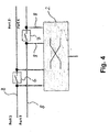
Figur 4 ist dargestellt, dass ein Netzwerkgerät (hier das Netzwerkgerät 2) vier Ports (Port 1, Port 2, Port 3, Port 4) aufweist, über welches dieses Netzwerkgerät 2 in dem Netzwerk 1 eingesetzt ist. - Zur Realisierung der Funktionen, die in den
Figuren 1 bis 3 dargestellt und vorstehend beschrieben sind, ist erfindungsgemäß jeweils ein Überbrückungsschalter 6 zur Überbrückung von Port 1 und Port 2 sowie ein weiterer Überbrückungsschalter 7 zur Überbrückung von Port 3 und Port 4 des Netzwerkgerätes 2 vorhanden (auch weniger oder mehr als zwei Überbrückungsschalter wie in diesem Ausführungsbeispiel). Sollte also, wie im Zusammenhang mit denFiguren 1 bis 3 beschrieben, eines der Netzwerkgeräte (bei denen es sich nicht immer zwangsweise um das Netzwerkgerät 2 handeln muss) ausfallen, werden unmittelbar die Überbrückungsschalter 6, 7 betätigt, um die angeschlossenen Ports quasi kurzzuschließen. Damit wird wirksam und in vorteilhafter Weise vermieden, dass der Datenring unterbrochen wird, solange ein neues Netzwerkgerät als Master aktiviert worden ist. Dadurch lässt sich in vorteilhafter Weise die Überbrückungszeit, bis ein anders Netzwerkgerät als Master aktiviert worden ist, deutlich senken und die Redundanzfunktion für die übrigen Teilnehmer erhalten. Dabei wird zwar für eine kurze Zeit in Kauf genommen, dass der Datenring des Netzwerkes 1 komplett geschlossen ist und Datenpakete möglicherweise in einer Endlosschleife kreisen könnten. Da dies jedoch nur sehr kurzzeitig möglich ist, bis nämlich die beiden Überbrückungsschalter 6, 7 wieder geöffnet werden, kann dies im Sinne der Realisierung einer äußerst kurzem Umschaltzeit von dem alten aktiven, aber ausgefallenen Master hin zu dem Einsatz des neuen Masters in Kauf genommen werden. - Die Überbrückungsschalter 6, 7 schließen die jeweilige Leitung 8 kurz, sobald der Strom ausfällt und sie öffnen wieder, wenn das ausgefallene Netzwerkgerät vollständig gebootet ist. Im Normalbetrieb sind die Überbrückungsschalter 6, 7 geöffnet.
-
- 1.
- Netzwerk
- 2.
- Netzwerkgerät
- 3.
- Netzwerkgerät
- 4.
- Netzwerkgerät
- 5.
- Netzwerkgerät
- 6.
- Überbrückungsschalter
- 7.
- Überbrückungsschalter
- 8.
- Leitungen
Claims (2)
- Verfahren zum Betreiben eines Netzwerkes (1) nach einem Multi-Master-Redundanz-Verfahren mit einer Redundanzfunktion, wobei in dem Netzwerk (1) mehrere Netzwerkgeräte (2 bis 5) in einer Ringtopologie über Leitungen (8) miteinander verbunden sind und Daten austauschen, wobei für den Fall, dass eines der Netzwerkgeräte (2 bis 5) ausfällt, zwei Ports des ausgefallenen Netzwerkgerätes (2 bis 5), die einer der Leitungen zugehörig sind, mittels eines Überbrückungsschalters (6, 7) auf der physikalischen Ebene miteinander verbunden werden, dadurch gekennzeichnet, dass der Überbrückungsschalter (6, 7) die jeweilige Leitung (8) kurzschließt, sobald der Strom ausfällt und sie wieder öffnet, , wenn das ausgefallene Netzwerkgerät (2 bis 5) vollständig gebootet ist, wobei die Redundanzfunktion nach einem Multi-Master-Redundanz-Verfahren realisiert wird und das Multi-Master-Redundanz-Verfahren als ein Device-Level-Ring-Verfahren realisiert wird.
- Verfahren nach Anspruch 1 dadurch gekennzeichnet, dass die Verbindung der beiden Ports des ausgefallenen Netzwerkgerätes (2 bis 5) aufgehoben wird, wenn ein anderes als das ausgefallene Netzwerkgeräte (2 bis 5) als Master aktiviert wurde.
Applications Claiming Priority (2)
| Application Number | Priority Date | Filing Date | Title |
|---|---|---|---|
| DE102015210304 | 2015-06-03 | ||
| PCT/EP2016/062685 WO2016193450A1 (de) | 2015-06-03 | 2016-06-03 | Verfahren zum betreiben eines netzwerkes mit einem multi-master-redundanz-protokolls und einer zusätzlichen redundanzfunktion mittels überbrückungsschalter |
Publications (2)
| Publication Number | Publication Date |
|---|---|
| EP3304827A1 EP3304827A1 (de) | 2018-04-11 |
| EP3304827B1 true EP3304827B1 (de) | 2021-08-25 |
Family
ID=56101461
Family Applications (1)
| Application Number | Title | Priority Date | Filing Date |
|---|---|---|---|
| EP16727187.3A Active EP3304827B1 (de) | 2015-06-03 | 2016-06-03 | Verfahren zum betreiben eines netzwerkes mit einem multi-master-redundanz-protokoll und einer zusätzlichen redundanzfunktion mittels überbrückungsschalter |
Country Status (5)
| Country | Link |
|---|---|
| US (1) | US10826721B2 (de) |
| EP (1) | EP3304827B1 (de) |
| CN (1) | CN107667506B (de) |
| DE (1) | DE102016110334A1 (de) |
| WO (1) | WO2016193450A1 (de) |
Family Cites Families (9)
| Publication number | Priority date | Publication date | Assignee | Title |
|---|---|---|---|---|
| US6944118B2 (en) | 1997-10-08 | 2005-09-13 | Bandwidth Technology Corp. | System and method for communicating digital information using time-and-frequency-bounded base functions |
| JP4108877B2 (ja) * | 1998-07-10 | 2008-06-25 | 松下電器産業株式会社 | ネットワークシステム,ネットワーク端末,およびネットワークシステムにおける障害箇所の特定方法 |
| EP1367778A1 (de) * | 2002-05-31 | 2003-12-03 | Fujitsu Siemens Computers, LLC | Vernetztes Computersystem und Methode unter Verwendung eines doppelten bidirektionalen Kommunikationsrings |
| US7533166B2 (en) * | 2002-12-05 | 2009-05-12 | Siemens Communications, Inc. | Method and system for router misconfiguration autodetection |
| ATE472873T1 (de) * | 2005-04-14 | 2010-07-15 | Baumueller Anlagen Systemtech | Ausfall- und auskopplungstolerantes kommunikations-netzwerk, datenpfad- umschalteinrichtung und entsprechendes verfahren |
| EP2309678B1 (de) | 2009-10-08 | 2013-04-24 | Nxp B.V. | Ethernet-Netzwerkkomponente |
| CN101741674A (zh) * | 2009-12-22 | 2010-06-16 | 上海自动化仪表股份有限公司 | 一种以太网实现环网冗余和网络恢复的方法 |
| WO2013034188A1 (de) * | 2011-09-08 | 2013-03-14 | Siemens Aktiengesellschaft | Verfahren zum betreiben einer netzwerkkomponente in einem kommunikationsnetzwerk und netzwerkkomponente |
| DE102012209108B4 (de) * | 2012-05-30 | 2014-05-15 | Siemens Aktiengesellschaft | Netzwerkeinrichtung, Netzwerkanordnung und Verfahren zum Betreiben einer Netzwerkanordnung |
-
2016
- 2016-06-03 EP EP16727187.3A patent/EP3304827B1/de active Active
- 2016-06-03 CN CN201680032012.XA patent/CN107667506B/zh active Active
- 2016-06-03 US US15/571,205 patent/US10826721B2/en active Active
- 2016-06-03 DE DE102016110334.9A patent/DE102016110334A1/de not_active Ceased
- 2016-06-03 WO PCT/EP2016/062685 patent/WO2016193450A1/de not_active Ceased
Non-Patent Citations (1)
| Title |
|---|
| None * |
Also Published As
| Publication number | Publication date |
|---|---|
| WO2016193450A1 (de) | 2016-12-08 |
| US20180115437A1 (en) | 2018-04-26 |
| US10826721B2 (en) | 2020-11-03 |
| EP3304827A1 (de) | 2018-04-11 |
| CN107667506A (zh) | 2018-02-06 |
| DE102016110334A1 (de) | 2016-12-08 |
| CN107667506B (zh) | 2021-07-06 |
Similar Documents
| Publication | Publication Date | Title |
|---|---|---|
| DE102011082965A1 (de) | Verfahren zum Betreiben einer Netzwerkanordnung und Netzwerkanordnung | |
| DE102010011965A1 (de) | Parallelbetrieb von RSTP (Rapid Spanning Tree Protocol) und MRP (Media Redundancy Protocol) und Segmentierung/Kopplung | |
| DE102018202148B3 (de) | Hydraulikventilverband mit Zwangsschaltung und Mobilhydrauliksystem | |
| DE102007016432A1 (de) | Verfahren zur Konfiguration des Redundanzprotokolls auf Geräten in einem redundanten Ringnetzwerk | |
| EP1955480B1 (de) | Netzwerk mit redundanzeigenschaften, ethernet-switch für ein derartiges netzwerk sowie verfahren zur konfiguration eines derartigen netzwerks | |
| EP2359540B1 (de) | Verfahren zum anschluss von netzsegmenten mit redundanzeigenschaften an ein beliebiges netzwerk | |
| EP2842145B1 (de) | Elektrische schaltanlage | |
| WO2016193450A1 (de) | Verfahren zum betreiben eines netzwerkes mit einem multi-master-redundanz-protokolls und einer zusätzlichen redundanzfunktion mittels überbrückungsschalter | |
| DE102016113322A1 (de) | Slave-Steuerung für Ethernet-Netzwerk | |
| DE102005003060A1 (de) | Verfahren zur Handhabung von Unterbrechungen in einem Ethernet-Ring | |
| EP3332506B1 (de) | Verfahren zum betreiben eines datenübertragungssystems und datenübertragungssystem | |
| DE2520670B2 (de) | Umschaltanordnung für Lastumschalter von Stufenschaltern für Stufentransformatoren | |
| DE102018113982B4 (de) | Laststufenschalter und verfahren zur betätigung eines laststufenschalters | |
| EP2817923B1 (de) | Rechnernetzwerk mit einer ringförmigen busverbindung | |
| EP2756575B1 (de) | Energieverteilnetz | |
| WO2015127947A1 (de) | Trafostufenschalter | |
| DE102005024309A1 (de) | Einschaltverriegelung für einen Antrieb eines sich längs einer Fahrbahn bewegenden Fahrzeugs, insbesondere einer Magnetschwebebahn, sowie Antrieb mit einer entsprechenden Einschaltverriegelung | |
| DE4328068C1 (de) | Verfahren zum Ermitteln eines Ersatzweges in einem gedoppelten ringförmigen Kommunikationsnetz | |
| EP2582211B1 (de) | DALI Verteilerbox | |
| DE1588616C (de) | Schaltvorrichtung fur Trennschalter zum Lokalisieren von Leitungsschaden | |
| EP3261276B1 (de) | Verfahren zur effizienteren datenübertragung in einem optischen telekommunikationsnetz im wellenlängen-multiplex-betrieb, und optisches telekommunikationsnetz, computerprogramm und computerprogrammprodukt | |
| DE19831921A1 (de) | System zum Übertragen von Daten über einen differentiellen Bus | |
| DE2527162C2 (de) | Einrichtung zur Übertragung von Digitalsignalen in Fernmeldenetzen mit analogen und digitalen Übertragungsabschnitten | |
| DE102012012131A1 (de) | Verfahren zur rückwirkungsfreien, redundanten Kopplung von Kommunikationsnetzen mittels des Rapid Spanning Tree Protocols | |
| DE1939133A1 (de) | Schaltungsanordnung fuer Empfaenger in Rundsteueranlagen |
Legal Events
| Date | Code | Title | Description |
|---|---|---|---|
| STAA | Information on the status of an ep patent application or granted ep patent |
Free format text: STATUS: THE INTERNATIONAL PUBLICATION HAS BEEN MADE |
|
| PUAI | Public reference made under article 153(3) epc to a published international application that has entered the european phase |
Free format text: ORIGINAL CODE: 0009012 |
|
| STAA | Information on the status of an ep patent application or granted ep patent |
Free format text: STATUS: REQUEST FOR EXAMINATION WAS MADE |
|
| 17P | Request for examination filed |
Effective date: 20171102 |
|
| AK | Designated contracting states |
Kind code of ref document: A1 Designated state(s): AL AT BE BG CH CY CZ DE DK EE ES FI FR GB GR HR HU IE IS IT LI LT LU LV MC MK MT NL NO PL PT RO RS SE SI SK SM TR |
|
| AX | Request for extension of the european patent |
Extension state: BA ME |
|
| DAV | Request for validation of the european patent (deleted) | ||
| DAX | Request for extension of the european patent (deleted) | ||
| STAA | Information on the status of an ep patent application or granted ep patent |
Free format text: STATUS: EXAMINATION IS IN PROGRESS |
|
| 17Q | First examination report despatched |
Effective date: 20190304 |
|
| GRAP | Despatch of communication of intention to grant a patent |
Free format text: ORIGINAL CODE: EPIDOSNIGR1 |
|
| STAA | Information on the status of an ep patent application or granted ep patent |
Free format text: STATUS: GRANT OF PATENT IS INTENDED |
|
| INTG | Intention to grant announced |
Effective date: 20210409 |
|
| RIN1 | Information on inventor provided before grant (corrected) |
Inventor name: DER ERFINDER HAT AUF SEIN RECHT VERZICHTET, ALS SOLCHER BEKANNT GEMACHT ZU WERDEN. |
|
| GRAS | Grant fee paid |
Free format text: ORIGINAL CODE: EPIDOSNIGR3 |
|
| GRAA | (expected) grant |
Free format text: ORIGINAL CODE: 0009210 |
|
| STAA | Information on the status of an ep patent application or granted ep patent |
Free format text: STATUS: THE PATENT HAS BEEN GRANTED |
|
| AK | Designated contracting states |
Kind code of ref document: B1 Designated state(s): AL AT BE BG CH CY CZ DE DK EE ES FI FR GB GR HR HU IE IS IT LI LT LU LV MC MK MT NL NO PL PT RO RS SE SI SK SM TR |
|
| REG | Reference to a national code |
Ref country code: CH Ref legal event code: EP |
|
| REG | Reference to a national code |
Ref country code: DE Ref legal event code: R096 Ref document number: 502016013699 Country of ref document: DE |
|
| REG | Reference to a national code |
Ref country code: IE Ref legal event code: FG4D Free format text: LANGUAGE OF EP DOCUMENT: GERMAN Ref country code: AT Ref legal event code: REF Ref document number: 1424955 Country of ref document: AT Kind code of ref document: T Effective date: 20210915 |
|
| REG | Reference to a national code |
Ref country code: LT Ref legal event code: MG9D |
|
| REG | Reference to a national code |
Ref country code: NL Ref legal event code: MP Effective date: 20210825 |
|
| PG25 | Lapsed in a contracting state [announced via postgrant information from national office to epo] |
Ref country code: PT Free format text: LAPSE BECAUSE OF FAILURE TO SUBMIT A TRANSLATION OF THE DESCRIPTION OR TO PAY THE FEE WITHIN THE PRESCRIBED TIME-LIMIT Effective date: 20211227 Ref country code: NO Free format text: LAPSE BECAUSE OF FAILURE TO SUBMIT A TRANSLATION OF THE DESCRIPTION OR TO PAY THE FEE WITHIN THE PRESCRIBED TIME-LIMIT Effective date: 20211125 Ref country code: ES Free format text: LAPSE BECAUSE OF FAILURE TO SUBMIT A TRANSLATION OF THE DESCRIPTION OR TO PAY THE FEE WITHIN THE PRESCRIBED TIME-LIMIT Effective date: 20210825 Ref country code: FI Free format text: LAPSE BECAUSE OF FAILURE TO SUBMIT A TRANSLATION OF THE DESCRIPTION OR TO PAY THE FEE WITHIN THE PRESCRIBED TIME-LIMIT Effective date: 20210825 Ref country code: HR Free format text: LAPSE BECAUSE OF FAILURE TO SUBMIT A TRANSLATION OF THE DESCRIPTION OR TO PAY THE FEE WITHIN THE PRESCRIBED TIME-LIMIT Effective date: 20210825 Ref country code: BG Free format text: LAPSE BECAUSE OF FAILURE TO SUBMIT A TRANSLATION OF THE DESCRIPTION OR TO PAY THE FEE WITHIN THE PRESCRIBED TIME-LIMIT Effective date: 20211125 Ref country code: LT Free format text: LAPSE BECAUSE OF FAILURE TO SUBMIT A TRANSLATION OF THE DESCRIPTION OR TO PAY THE FEE WITHIN THE PRESCRIBED TIME-LIMIT Effective date: 20210825 Ref country code: RS Free format text: LAPSE BECAUSE OF FAILURE TO SUBMIT A TRANSLATION OF THE DESCRIPTION OR TO PAY THE FEE WITHIN THE PRESCRIBED TIME-LIMIT Effective date: 20210825 Ref country code: SE Free format text: LAPSE BECAUSE OF FAILURE TO SUBMIT A TRANSLATION OF THE DESCRIPTION OR TO PAY THE FEE WITHIN THE PRESCRIBED TIME-LIMIT Effective date: 20210825 |
|
| PG25 | Lapsed in a contracting state [announced via postgrant information from national office to epo] |
Ref country code: PL Free format text: LAPSE BECAUSE OF FAILURE TO SUBMIT A TRANSLATION OF THE DESCRIPTION OR TO PAY THE FEE WITHIN THE PRESCRIBED TIME-LIMIT Effective date: 20210825 Ref country code: LV Free format text: LAPSE BECAUSE OF FAILURE TO SUBMIT A TRANSLATION OF THE DESCRIPTION OR TO PAY THE FEE WITHIN THE PRESCRIBED TIME-LIMIT Effective date: 20210825 |
|
| PG25 | Lapsed in a contracting state [announced via postgrant information from national office to epo] |
Ref country code: NL Free format text: LAPSE BECAUSE OF FAILURE TO SUBMIT A TRANSLATION OF THE DESCRIPTION OR TO PAY THE FEE WITHIN THE PRESCRIBED TIME-LIMIT Effective date: 20210825 |
|
| PG25 | Lapsed in a contracting state [announced via postgrant information from national office to epo] |
Ref country code: DK Free format text: LAPSE BECAUSE OF FAILURE TO SUBMIT A TRANSLATION OF THE DESCRIPTION OR TO PAY THE FEE WITHIN THE PRESCRIBED TIME-LIMIT Effective date: 20210825 |
|
| REG | Reference to a national code |
Ref country code: DE Ref legal event code: R097 Ref document number: 502016013699 Country of ref document: DE |
|
| PG25 | Lapsed in a contracting state [announced via postgrant information from national office to epo] |
Ref country code: SM Free format text: LAPSE BECAUSE OF FAILURE TO SUBMIT A TRANSLATION OF THE DESCRIPTION OR TO PAY THE FEE WITHIN THE PRESCRIBED TIME-LIMIT Effective date: 20210825 Ref country code: SK Free format text: LAPSE BECAUSE OF FAILURE TO SUBMIT A TRANSLATION OF THE DESCRIPTION OR TO PAY THE FEE WITHIN THE PRESCRIBED TIME-LIMIT Effective date: 20210825 Ref country code: RO Free format text: LAPSE BECAUSE OF FAILURE TO SUBMIT A TRANSLATION OF THE DESCRIPTION OR TO PAY THE FEE WITHIN THE PRESCRIBED TIME-LIMIT Effective date: 20210825 Ref country code: EE Free format text: LAPSE BECAUSE OF FAILURE TO SUBMIT A TRANSLATION OF THE DESCRIPTION OR TO PAY THE FEE WITHIN THE PRESCRIBED TIME-LIMIT Effective date: 20210825 Ref country code: CZ Free format text: LAPSE BECAUSE OF FAILURE TO SUBMIT A TRANSLATION OF THE DESCRIPTION OR TO PAY THE FEE WITHIN THE PRESCRIBED TIME-LIMIT Effective date: 20210825 Ref country code: AL Free format text: LAPSE BECAUSE OF FAILURE TO SUBMIT A TRANSLATION OF THE DESCRIPTION OR TO PAY THE FEE WITHIN THE PRESCRIBED TIME-LIMIT Effective date: 20210825 |
|
| PLBE | No opposition filed within time limit |
Free format text: ORIGINAL CODE: 0009261 |
|
| STAA | Information on the status of an ep patent application or granted ep patent |
Free format text: STATUS: NO OPPOSITION FILED WITHIN TIME LIMIT |
|
| PG25 | Lapsed in a contracting state [announced via postgrant information from national office to epo] |
Ref country code: IT Free format text: LAPSE BECAUSE OF FAILURE TO SUBMIT A TRANSLATION OF THE DESCRIPTION OR TO PAY THE FEE WITHIN THE PRESCRIBED TIME-LIMIT Effective date: 20210825 |
|
| 26N | No opposition filed |
Effective date: 20220527 |
|
| PG25 | Lapsed in a contracting state [announced via postgrant information from national office to epo] |
Ref country code: SI Free format text: LAPSE BECAUSE OF FAILURE TO SUBMIT A TRANSLATION OF THE DESCRIPTION OR TO PAY THE FEE WITHIN THE PRESCRIBED TIME-LIMIT Effective date: 20210825 |
|
| PG25 | Lapsed in a contracting state [announced via postgrant information from national office to epo] |
Ref country code: MC Free format text: LAPSE BECAUSE OF FAILURE TO SUBMIT A TRANSLATION OF THE DESCRIPTION OR TO PAY THE FEE WITHIN THE PRESCRIBED TIME-LIMIT Effective date: 20210825 |
|
| REG | Reference to a national code |
Ref country code: CH Ref legal event code: PL |
|
| REG | Reference to a national code |
Ref country code: BE Ref legal event code: MM Effective date: 20220630 |
|
| PG25 | Lapsed in a contracting state [announced via postgrant information from national office to epo] |
Ref country code: LU Free format text: LAPSE BECAUSE OF NON-PAYMENT OF DUE FEES Effective date: 20220603 Ref country code: LI Free format text: LAPSE BECAUSE OF NON-PAYMENT OF DUE FEES Effective date: 20220630 Ref country code: IE Free format text: LAPSE BECAUSE OF NON-PAYMENT OF DUE FEES Effective date: 20220603 Ref country code: FR Free format text: LAPSE BECAUSE OF NON-PAYMENT OF DUE FEES Effective date: 20220630 Ref country code: CH Free format text: LAPSE BECAUSE OF NON-PAYMENT OF DUE FEES Effective date: 20220630 |
|
| PG25 | Lapsed in a contracting state [announced via postgrant information from national office to epo] |
Ref country code: BE Free format text: LAPSE BECAUSE OF NON-PAYMENT OF DUE FEES Effective date: 20220630 |
|
| REG | Reference to a national code |
Ref country code: AT Ref legal event code: MM01 Ref document number: 1424955 Country of ref document: AT Kind code of ref document: T Effective date: 20220603 |
|
| PG25 | Lapsed in a contracting state [announced via postgrant information from national office to epo] |
Ref country code: AT Free format text: LAPSE BECAUSE OF NON-PAYMENT OF DUE FEES Effective date: 20220603 |
|
| PG25 | Lapsed in a contracting state [announced via postgrant information from national office to epo] |
Ref country code: HU Free format text: LAPSE BECAUSE OF FAILURE TO SUBMIT A TRANSLATION OF THE DESCRIPTION OR TO PAY THE FEE WITHIN THE PRESCRIBED TIME-LIMIT; INVALID AB INITIO Effective date: 20160603 |
|
| PG25 | Lapsed in a contracting state [announced via postgrant information from national office to epo] |
Ref country code: MK Free format text: LAPSE BECAUSE OF FAILURE TO SUBMIT A TRANSLATION OF THE DESCRIPTION OR TO PAY THE FEE WITHIN THE PRESCRIBED TIME-LIMIT Effective date: 20210825 Ref country code: CY Free format text: LAPSE BECAUSE OF FAILURE TO SUBMIT A TRANSLATION OF THE DESCRIPTION OR TO PAY THE FEE WITHIN THE PRESCRIBED TIME-LIMIT Effective date: 20210825 |
|
| PG25 | Lapsed in a contracting state [announced via postgrant information from national office to epo] |
Ref country code: TR Free format text: LAPSE BECAUSE OF FAILURE TO SUBMIT A TRANSLATION OF THE DESCRIPTION OR TO PAY THE FEE WITHIN THE PRESCRIBED TIME-LIMIT Effective date: 20210825 |
|
| PG25 | Lapsed in a contracting state [announced via postgrant information from national office to epo] |
Ref country code: MT Free format text: LAPSE BECAUSE OF FAILURE TO SUBMIT A TRANSLATION OF THE DESCRIPTION OR TO PAY THE FEE WITHIN THE PRESCRIBED TIME-LIMIT Effective date: 20210825 |
|
| PG25 | Lapsed in a contracting state [announced via postgrant information from national office to epo] |
Ref country code: GR Free format text: LAPSE BECAUSE OF NON-PAYMENT OF DUE FEES Effective date: 20210825 |
|
| PG25 | Lapsed in a contracting state [announced via postgrant information from national office to epo] |
Ref country code: GR Free format text: LAPSE BECAUSE OF NON-PAYMENT OF DUE FEES Effective date: 20210825 |
|
| PGFP | Annual fee paid to national office [announced via postgrant information from national office to epo] |
Ref country code: GB Payment date: 20260629 Year of fee payment: 11 |
|
| PGFP | Annual fee paid to national office [announced via postgrant information from national office to epo] |
Ref country code: DE Payment date: 20260629 Year of fee payment: 11 |