EP3304565B1 - Längliche leiter und verfahren zur herstellung und verwendung davon - Google Patents
Längliche leiter und verfahren zur herstellung und verwendung davon Download PDFInfo
- Publication number
- EP3304565B1 EP3304565B1 EP16803986.5A EP16803986A EP3304565B1 EP 3304565 B1 EP3304565 B1 EP 3304565B1 EP 16803986 A EP16803986 A EP 16803986A EP 3304565 B1 EP3304565 B1 EP 3304565B1
- Authority
- EP
- European Patent Office
- Prior art keywords
- elongated
- conducting members
- elongated conductor
- conductor
- proximal
- Prior art date
- Legal status (The legal status is an assumption and is not a legal conclusion. Google has not performed a legal analysis and makes no representation as to the accuracy of the status listed.)
- Active
Links
Images


Classifications
-
- A—HUMAN NECESSITIES
- A61—MEDICAL OR VETERINARY SCIENCE; HYGIENE
- A61B—DIAGNOSIS; SURGERY; IDENTIFICATION
- A61B5/00—Measuring for diagnostic purposes; Identification of persons
- A61B5/68—Arrangements of detecting, measuring or recording means, e.g. sensors, in relation to patient
- A61B5/6846—Arrangements of detecting, measuring or recording means, e.g. sensors, in relation to patient specially adapted to be brought in contact with an internal body part, i.e. invasive
- A61B5/6867—Arrangements of detecting, measuring or recording means, e.g. sensors, in relation to patient specially adapted to be brought in contact with an internal body part, i.e. invasive specially adapted to be attached or implanted in a specific body part
- A61B5/6876—Blood vessel
-
- A—HUMAN NECESSITIES
- A61—MEDICAL OR VETERINARY SCIENCE; HYGIENE
- A61B—DIAGNOSIS; SURGERY; IDENTIFICATION
- A61B18/00—Surgical instruments, devices or methods for transferring non-mechanical forms of energy to or from the body
- A61B18/04—Surgical instruments, devices or methods for transferring non-mechanical forms of energy to or from the body by heating
- A61B18/12—Surgical instruments, devices or methods for transferring non-mechanical forms of energy to or from the body by heating by passing a current through the tissue to be heated, e.g. high-frequency current
- A61B18/14—Probes or electrodes therefor
- A61B18/1492—Probes or electrodes therefor having a flexible, catheter-like structure, e.g. for heart ablation
-
- A—HUMAN NECESSITIES
- A61—MEDICAL OR VETERINARY SCIENCE; HYGIENE
- A61B—DIAGNOSIS; SURGERY; IDENTIFICATION
- A61B5/00—Measuring for diagnostic purposes; Identification of persons
- A61B5/68—Arrangements of detecting, measuring or recording means, e.g. sensors, in relation to patient
- A61B5/6846—Arrangements of detecting, measuring or recording means, e.g. sensors, in relation to patient specially adapted to be brought in contact with an internal body part, i.e. invasive
- A61B5/6847—Arrangements of detecting, measuring or recording means, e.g. sensors, in relation to patient specially adapted to be brought in contact with an internal body part, i.e. invasive mounted on an invasive device
- A61B5/6852—Catheters
-
- A—HUMAN NECESSITIES
- A61—MEDICAL OR VETERINARY SCIENCE; HYGIENE
- A61M—DEVICES FOR INTRODUCING MEDIA INTO, OR ONTO, THE BODY; DEVICES FOR TRANSDUCING BODY MEDIA OR FOR TAKING MEDIA FROM THE BODY; DEVICES FOR PRODUCING OR ENDING SLEEP OR STUPOR
- A61M25/00—Catheters; Hollow probes
-
- A—HUMAN NECESSITIES
- A61—MEDICAL OR VETERINARY SCIENCE; HYGIENE
- A61N—ELECTROTHERAPY; MAGNETOTHERAPY; RADIATION THERAPY; ULTRASOUND THERAPY
- A61N1/00—Electrotherapy; Circuits therefor
- A61N1/02—Details
- A61N1/04—Electrodes
- A61N1/0404—Electrodes for external use
- A61N1/0472—Structure-related aspects
- A61N1/0488—Details about the lead
-
- A—HUMAN NECESSITIES
- A61—MEDICAL OR VETERINARY SCIENCE; HYGIENE
- A61N—ELECTROTHERAPY; MAGNETOTHERAPY; RADIATION THERAPY; ULTRASOUND THERAPY
- A61N1/00—Electrotherapy; Circuits therefor
- A61N1/02—Details
- A61N1/04—Electrodes
- A61N1/05—Electrodes for implantation or insertion into the body, e.g. heart electrode
-
- H—ELECTRICITY
- H01—ELECTRIC ELEMENTS
- H01B—CABLES; CONDUCTORS; INSULATORS; SELECTION OF MATERIALS FOR THEIR CONDUCTIVE, INSULATING OR DIELECTRIC PROPERTIES
- H01B13/00—Apparatus or processes specially adapted for manufacturing conductors or cables
- H01B13/06—Insulating conductors or cables
-
- H—ELECTRICITY
- H01—ELECTRIC ELEMENTS
- H01B—CABLES; CONDUCTORS; INSULATORS; SELECTION OF MATERIALS FOR THEIR CONDUCTIVE, INSULATING OR DIELECTRIC PROPERTIES
- H01B7/00—Insulated conductors or cables characterised by their form
- H01B7/02—Disposition of insulation
-
- H—ELECTRICITY
- H01—ELECTRIC ELEMENTS
- H01B—CABLES; CONDUCTORS; INSULATORS; SELECTION OF MATERIALS FOR THEIR CONDUCTIVE, INSULATING OR DIELECTRIC PROPERTIES
- H01B7/00—Insulated conductors or cables characterised by their form
- H01B7/08—Flat or ribbon cables
- H01B7/0846—Parallel wires, fixed upon a support layer
-
- A—HUMAN NECESSITIES
- A61—MEDICAL OR VETERINARY SCIENCE; HYGIENE
- A61B—DIAGNOSIS; SURGERY; IDENTIFICATION
- A61B17/00—Surgical instruments, devices or methods
- A61B2017/00526—Methods of manufacturing
-
- A—HUMAN NECESSITIES
- A61—MEDICAL OR VETERINARY SCIENCE; HYGIENE
- A61B—DIAGNOSIS; SURGERY; IDENTIFICATION
- A61B18/00—Surgical instruments, devices or methods for transferring non-mechanical forms of energy to or from the body
- A61B2018/00053—Mechanical features of the instrument of device
- A61B2018/00172—Connectors and adapters therefor
- A61B2018/00178—Electrical connectors
-
- A—HUMAN NECESSITIES
- A61—MEDICAL OR VETERINARY SCIENCE; HYGIENE
- A61B—DIAGNOSIS; SURGERY; IDENTIFICATION
- A61B2562/00—Details of sensors; Constructional details of sensor housings or probes; Accessories for sensors
- A61B2562/12—Manufacturing methods specially adapted for producing sensors for in-vivo measurements
- A61B2562/125—Manufacturing methods specially adapted for producing sensors for in-vivo measurements characterised by the manufacture of electrodes
-
- A—HUMAN NECESSITIES
- A61—MEDICAL OR VETERINARY SCIENCE; HYGIENE
- A61B—DIAGNOSIS; SURGERY; IDENTIFICATION
- A61B2562/00—Details of sensors; Constructional details of sensor housings or probes; Accessories for sensors
- A61B2562/22—Arrangements of medical sensors with cables or leads; Connectors or couplings specifically adapted for medical sensors
- A61B2562/221—Arrangements of sensors with cables or leads, e.g. cable harnesses
- A61B2562/222—Electrical cables or leads therefor, e.g. coaxial cables or ribbon cables
-
- H—ELECTRICITY
- H01—ELECTRIC ELEMENTS
- H01B—CABLES; CONDUCTORS; INSULATORS; SELECTION OF MATERIALS FOR THEIR CONDUCTIVE, INSULATING OR DIELECTRIC PROPERTIES
- H01B7/00—Insulated conductors or cables characterised by their form
- H01B7/08—Flat or ribbon cables
- H01B7/0892—Flat or ribbon cables incorporated in a cable of non-flat configuration
Definitions
- elongated conductor refers to an elongated structure having a proximal region and a distal region, which structure is configured to convey some entity, e.g., electrical current, charge, light, heat, a fluid, a gel, a biological sample, etc., from the proximal region to the distal region or vice versa.
- some entity e.g., electrical current, charge, light, heat, a fluid, a gel, a biological sample, etc.
- the elongated conductor has an elongated structure in which the length (extending from the proximal end of the proximal region to the distal end of the distal region) is longer than the longest cross-sectional dimension of the structure.
- the elongated conductors may be configured to convey different entities, e.g., electrical current, charge, light, heat, a fluid, a gel, a biological sample, etc.
- the conductors are configured to convey electric current, such that they are electrical conductors.
- the conductors are meant to convey light, such that they are optical fibers.
- the elongated conductors may include a lumen, such that is meant to convey a fluid, a gel, a biological sample, etc.
- Elongated conductors of the invention include two or more insulated conducting members that are in fixed relative position along at least a portion of the elongated structure and extend from the proximal region to the distal region of the elongated structure.
- the conducting members are insulated and extend from a proximal region to a distal region of the elongated structure, they include an elongated component of a conductive material, e.g., an electrically conductive material, which is surrounded on all sides, e.g., coated, with an insulating material.
- the dimensions of the conductive material elongated component may vary, where in some instances the elongated component has a length ranging from 5 to 4,000 mm, such as 50 to 2,000 mm and a diameter ranging from 0.004 to 1.0 mm, such as 0.01 to 0.1 mm.
- the thickness of the insulating material, i.e., coating may also vary, ranging in some instances from 0.0001 to 0.1 mm, such as 0.003 to 0.040 mm.
- Each of the insulated conducting members of the structure may have the same dimensions, or two or more the insulating conductive members may have different dimensions, e.g., differ from each other in terms of diameter such that at least two of the two or more insulated conductors comprise conductors of differing diameter, as desired.
- the gauge of the conductor may be 40 AWG or greater, such as 45 AWG or greater, including 50 AWG or greater, with a center to center conducting member pitch (i.e., an insulated conducting member pitch) ranging from 6 to 250 ⁇ m, such as 12 to 75 ⁇ m and including 15 to 30 ⁇ m.
- a center to center conducting member pitch i.e., an insulated conducting member pitch
- one or more of the second conducting members may be arranged and nested in and around one or more of the first conducting members. Such an arrangement may be advantageous to optimize or match the power requirements to the packing density of the overall elongated conductor.
- the elongated conductors may include one or more sub-groupings of conducting members, each sub-grouping of conducting members arranged such that the spatial relationship between conducting members within the sub-group are relatively fixed with respect to each other.
- one or more of the sub-group members may be pre-fixed so as to form a local shield around one or more members of the sub-group.
- one or more pairs of sub-group members may be pre-fixed (e.g., linearly fixed together, wound together, etc.), so as to form a waveguide, a twisted pair, etc. Such an arrangement may be advantageous to control current flow and limit cross-talk between conducting members of the elongated conductor during use.
- two or more of the conducting members within an elongated conductor may be permanently bonded together at one or more lengths along the elongated conductor. Such permanent bonding may be advantageous to limit tribological noise associated with movement and flexure of the elongated conductor during use (e.g., such as during movement within lumen in a body, etc.).
- one or more of the conducting members may include a plurality of additional material layers, such as a first layer and a second layer.
- the first layer may be an insulating material, so as to substantially limit current flow, heat flow, light passage there through, as compared with passage along the length of the conducting material.
- the second layer may be a conducting layer, an insulating layer, a bonding layer, etc.
- one or more conducting members in an elongated conductor may be bound together via the second layers of the conducting members.
- one or more portions of the elongated conductor may be a substantially monolithic body in terms of movement, etc.
- the conducting members may mechanically behave as a composite structure, frictional movement between conducting members being substantially minimal during flexure thereof).
- Such an instance may be advantageous for improving handle-ability of the elongated conductor during assembly, minimizing noise between conducting members during use, improve impedance tolerance between adjacent conducting members in the elongated conductor, etc.
- the second layer may be constructed, at least in part from a conducting material.
- the conducting material may substantially provide a return path for current through the conducting member, may complete a capacitive function of the conducting member (i.e., the capacitor formed from the inner conducting material, the first insulating layer, and the conducting layer), etc.
- a plurality of such conducting members may be bonded together with the conducting layers, so as to provide an electrical shield for the elongated conductor, etc.
- the elongated conductor may include one or more additional structural members, the structural member providing mechanical rigidity, increased tensile strength, or the like for the overall elongated conductor.
- the structural member(s) may be arranged amid the conducting members, they may have a diameter that is similar to or different from the conducting members, or the like.
- the structural members may be formed from ultra-high tensile strength fibers, the structural members arranged amid the conducting members to improve the overall strength of the elongated conductor.
- the dimensions of the structural members may be selected so as to provide enhanced packing density of the overall elongated conductor.
- an elongated conductor may include one or more regions along the length thereof, wherein a sub-group of conducting members provided therein, may be physically separated from each other. Such a configuration may be advantageous to separate sub-groups for attachment to separate connectors at the ends of or along an intermediate length of the elongated conductor.
- the two or more insulated conducting members of the elongated conductor are in fixed relative position along at least a portion of the elongated structure.
- fixed relative position is meant that the conducting members are stably associated with each other, such that they do not move relative to each other, along at least portion of the elongated structure.
- the two or more conducting members are stably associated along at least a portion, they do not move relative to each other in that portion under operating conditions for which the elongated conductors are configured to be used.
- the two or more insulated conducting members behave as a composite structure along at least a portion of the elongated structure.
- the two or more conducting members may be fixed relative to each other along substantially the entire elongated structure.
- the length of such region(s) i.e., regions that are not stably associated with each other
- the number of such regions may also vary, where in some instances the number ranges from 1 to 50, such as 1 to 10, e.g., 1 to 2.
- the pattern is an axially aligned pattern of insulation openings.
- an axially aligned pattern of insulation openings is meant that the pattern of openings is positioned substantially along the long axis of the elongated conductor in the region of interest (e.g., a window associated with a particular conducting member may be known by the location of the window with respect to an end of the elongated conductor).
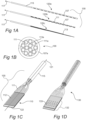
- FIG. 1A provides an illustration of an axially aligned pattern of insulation openings. As shown in FIG.
- the openings are axially arranged along the length of the assembled wires in an axially aligned pattern of insulation openings.
- the axially aligned pattern of insulation openings 113 is made up of an insulation opening in each of the different wires 111 making up the wire assembly of the of the elongated conductor 100 at the proximal end.
- the wire assembly is surrounded by a sheath 115, e.g., in accordance with embodiments.
- the remaining portion of the elongated conductor 100 is not specifically shown, but the proximal end 120 a,b,c is coupled 117 to other regions in of the elongated conductor, in accordance with embodiments.
- FIG. 1C provides an illustration of a transversely aligned pattern of insulation openings.
- distal end 110 of elongated conductor 100 includes insulated wires (111) assuming a flat configuration on the surface of a planar support 122.
- An insulation opening 112 is present in each of the insulated wires 111.
- the openings are transversely arranged across the assembled wires in a linear arrangement that is orthogonal to the long axis 121 of elongated conductor 100.
- the transversely aligned pattern of insulation openings 112 is made up of an insulation opening in each of the twelve different wires 111 making up the wire assembly of the of the elongated conductor 100.
- a particular conducting member may be provided with 3 or more insulation openings (e.g., such as to provide charge, current, light, etc. to a plurality of sites along the elongated conductor).
- the insulation openings 112 are shown in a purely orthogonal arrangement with respect to the long axis 121 of the elongated conductor 100.
- an alternative pattern may be warranted (e.g., so as to form a low profile interconnect with a flexible circuit, an integrated circuit, etc.).
- FIG. 1D provides an illustration of a substantially transversely aligned pattern of insulation openings 133 with a staggered pattern 132. It is noted that the staggering of the patterned 132 insulation removal is not required, but can be done to improve the pitch between wires without risking bridging between the contacts during reflow, thermocompressive fixation, or other type of post formed attachment or assembly process.
- FIG. 1E provides an illustration of a transverse aligned pattern of insulation openings as inserted 157 into a sheath 155.
- the patterned region of the elongated conductor 151 may be potted within the sheath 155.
- the patterned region may be attached to a component, a flexible circuit, an integrated circuit, a connector, etc.
- the elongated structure may include a split configuration and/or a length including a plurality of patterned regions.
- a split configuration means, a configuration where at least a portion of the conducting members within an elongated structure are separated from the others over a length, such that two or more separated groups of conducting members are present along a cross section over the length.
- the separated groups may be interfaced with separate connectors, may be interfaced with separate circuits, may be interfaced with the same circuit, may be configured so as to reduce an overall width of the elongate structure over the length, etc.
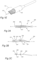
- FIGS. 2A - 2C provide views of different elongated conductors having different split transversely aligned patterns of insulation openings, in accordance with embodiments.
- FIG. 2A provides an illustration of a split-elongated conductor 200 with a split configuration.
- the split configuration includes a region with two sub-groups 201, 203 of conducting members that are individually patterned for separate attachment to a component 205.
- the component 205 is a flexible circuit, the sub-groups 201, 203 patterned 207, 209 so as to interface with matching patterns on the component 205.
- the sub-groups 201, 203 are shown supported by corresponding supporting members 207, 209.
- Such a configuration may be advantageous to provide a highly compact and easily handled approach to coupling an elongated conductor to a component 205.
- the split configuration may be advantageous to reduce the overall maximum transverse dimension of the elongated conductor in the vicinity of the sub-groups 201, 203.
- the split configuration is configured to provide operable coupling to opposing sides of a component, such as component 205.
- FIG. 2B provides an illustration of a split-elongated conductor 220 with a split configuration.
- the split configuration includes a region with two sub-groups 221, 223 of conducting members that are individually patterned for separate attachment to a component 225.
- the component 225 is an interposer patterned with conducting traces so as to interconnect one or more integrated circuits 227 to the sub-groups 221, 223.
- the sub-groups 221, 223 are patterned 229, 231 so as to interface with matching patterns on a surface of the component 225.
- the sub-groups 221, 223 are shown supported by corresponding supporting members 233, 235. Such a configuration may be advantageous to reduce the maximum transverse dimension of the elongated conductor in the vicinity of the component 225.
- the component 225 may include one or more sensors, processors, memory elements, analog to digital circuits, filters, serialization circuits, amplifiers, or the like.
- the split configuration is configured to provide operable coupling to the same side of a component, such as component 225.
- FIG. 2C provides an illustration of an elongated conductor including a plurality of patterned regions 243, 247, along the length of a sub-group of conducting members 240 therein.
- a first patterned region 243 is shown coupled with a component 245.
- the component 245 is a passive circuit element (e.g., a bypass capacitor, an inductor, etc.).
- a second patterned region 247 is shown coupled with a component 249.
- the component 249 is a system in package including a substrate and one or more integrated circuits 251.
- the patterned regions 245, 247 are separated by a distance, e.g., ranging from .01 to 25 mm, such as 1 to 15 mm, such that the flexibility of the overall elongated conductor is not substantially affected by the presence and interconnection with the components 245, 249.
- the patterned regions may be configured to interface with one or more interposers, inline bypassing circuits or elements, flip chips, silicon dies, sensors, electrodes, etc.
- the positioning of the patterned regions may be established such that the flexibility of the overall elongated conductor may be maintained during use.
- the components may be distributed along daisy chains of the patterned regions for maintaining flexibility, etc.
- the elongated structure includes a pattern of insulation openings at both the distal and proximal regions, the pattern is a different type of pattern in each of the proximal and distal regions.
- the elongated conductor may include both a transversely aligned pattern of insulation openings and an axially aligned pattern of insulation openings, where the transversely aligned pattern is present in one of the distal and proximal regions and the axially aligned pattern is present in the other of the distal and proximal regions.
- the arrangement of the different conducting members in the elongated conductor may vary, as desired.
- the different insulated conducting members assume a wound configuration along at least a portion of the elongated structure.
- wound configuration is meant that the conducting members are wound about a long axis of the elongated structure, such as the central long axis of the elongated structure.
- each conducting member of the wound configuration assumes a helical configuration.
- the pitch of the helical configuration may vary, ranging in some instances from 0.1 to 1,000 mm, such as 0.25 to 5 mm.
- the conducting members assume a wound configuration along at least a portion of the elongated structure.
- the wound configuration may extend along the complete length of the elongated structure, or along a portion thereof, e.g., 20% or more, 30% or more, 40% or more, 50% or more, 60% or more, 70% or more, 80% or more, up to 99%, such as 95%.
- the insulated conducting members are not present in a wound configuration along at least a portion of the elongated structure.
- the wound conducting members may be wound around a mandrel so as to form a tubular shape.
- the different insulated conducting members may assume a braided configuration along at least a portion of the elongated structure.
- braided configuration is meant that the conducting members are woven or plaited along a length of the elongated structure.
- the conducting members assume a braided configuration along at least a portion of the elongated structure.
- the braided configuration may extend along the complete length of the elongated structure, or along a portion thereof, e.g., 20% or more, 30% or more, 40% or more, 50% or more, 60% or more, 70% or more, 80% or more, up to 99%, such as 95%.
- the insulated conducting members are not present in a braided configuration along at least a portion of the elongated structure.
- the different insulated conducting members may assume a linear configuration along at least a portion of the elongated structure.
- linear configuration is meant that the conducting members along the elongated structure are configured in a linear or straight manner along a long axis of the elongated structure, such as the central long axis of the elongated structure.
- the conducting members assume a linear configuration along at least a portion of the elongated structure.
- the linear configuration may extend along the complete length of the elongated structure, or along a portion thereof, e.g., 20% or more, 30% or more, 40% or more, 50% or more, 60% or more, 70% or more, 80% or more, up to 99%, such as 95%.
- the insulated conducting members are not present in a linear configuration along at least a portion of the elongated structure.
- the insulated conducting members are configured to define a lumen along at least a portion of the elongated structure.
- the term "lumen” is used in its conventional sense to refer to an inner space or cavity, e.g., passageway, which extends along at least a portion of the elongated structure.
- the conducting members are configured to define the lumen, they are configured such that, collectively, they define the walls or boundaries of the lumen.
- the defined lumen may extend along the entire elongated structure, or only a portion of the elongated structure, e.g., 20% or more, 30% or more, 40% or more, 50% or more, 60% or more, 70% or more, 80% or more, up to 99%, such as 95%.
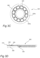
- FIG. 3A provides a view of the proximal end and FIG. 3B provides a view of the distal end of an elongated conductor in which the conducting members have been wound in manner to produce a lumen extending from the proximal to the distal end.
- proximal end 310 of elongated conductor 300 includes an assembly of wires 320 wound in a helical fashion that defines a central lumen 330.
- Each of the wires includes an insulation opening 325, where the collection of insulation openings make up a pattern of axially aligned insulation openings.
- the insulation openings 325 are coupled with one or more components 335.
- the components 335 may be contact pads on a connector, electrodes, etc.
- distal end 340 of elongated conductor 300 includes an assembly of wires 320 present in a planar configuration.
- Each of the wires includes an insulation opening 325, where the collection of insulation openings make up a pattern of transversely aligned insulation openings.
- regions 350 where the conducting members are not fixed, e.g., to provide strain relief.
- FIG. 3B also shows mandrel 360 which is used during fabrication of the structure as a guide about which the conducting members are wound to produce the central lumen.
- the mandrel 360 may include a removable part, such that after formation and fixation of the elongated conductor 300, the mandrel 360, or a portion thereof may be removed so as to form a lumen there through.
- FIG. 3C provides a cross sectional view of the proximal end of the elongated conductor 300 shown in FIG. 3A .
- the insulated wires 325 are shown in a wound pattern around the mandrel 360.
- the cross sectional view passes through a component 335a adjacent to an insulation window 325a, meant for coupling thereto.
- FIG. 3D provides an alternative view of the distal end of the elongated conductor 300 shown in FIG. 3A .
- the mandrel 360 is shown passing under the patterned region.
- the insulated wires 320 are supported by a substrate 370.
- the lumen may be suitable for passing a fluid along the length of the elongated conductor (e.g., for purposes of heating / cooling, delivery of a coolant, delivery of a drug, a medication, a biological sample, etc.). While the dimensions of the lumen may vary, in some instances the lumen has a diameter ranging from 0.025 to 20.0 mm, such as 0.10 to 5.0 mm and including 0.10 to 1.0 mm.
- the lumen may be occupied by one or more internal components.
- the lumen may be occupied by one or more internal conducting members, which conducting member(s) may occupy the entire lumen or a portion thereof.
- the elongated conductor includes a central insulated conductor surrounded by a plurality of peripheral insulated conductors, which peripheral conductors may be wound about the central conductor, braided about the central conductor, or linearly extend along the central conductor.
- the insulated conducting members may be present in a sheath.
- sheath is employed in its conventional sense to refer to an enveloping tubular structure.
- the sheath when present, may extend along the entire elongated structure, or only a portion of the elongated structure, e.g., 20% or more, 30% or more, 40% or more, 50% or more, 60% or more, 70% or more, 80% or more, up to 99%, such as 95%.
- the sheath is not present along at least a portion of the elongated structure.
- the sheath may be fabricated from any convenient material, as desired. In some instances, the sheath is fabricated from a conductive material.
- Conductive materials of interest for the sheath include, but are not limited to: a thermally conductive material, an optically conductive material, an electrically conductive material, a conductive polymer, a conducting composite, a metal, a precious metal, a conducting alloy, silver, copper, platinum, palladium, steel, carbon, stainless steel, an alloy thereof, a composite thereof, and the like.
- the sheath is fabricated from an insulating material.
- Insulating materials of interest for the sheath include, but are not limited to: a thermally insulating material, an optically reflective material, an electrically insulating material, a polymer, a thermoset polymer, a thermoplastic polymer, high strength fibers, a ceramic loaded polymer, a low dielectric polymer, a high field strength polymer, a composite thereof, and the like.
- the sheath is fabricated from a water-impermeable material, by which is meant that the sheath inhibits passage of water from one side of the sheet to the other.
- the sheath is fabricated from a water retaining material (e.g., a hygroscopic material, a hydrogel, etc.), such that the sheath may provide a lubricating surface for the elongated conductor when placed within an aqueous environment.
- a water retaining material e.g., a hygroscopic material, a hydrogel, etc.
- the insulated conducting members of at least one of the proximal and distal regions are stably associated with a substrate.
- the conducting members may be stably associated with a substrate, e.g., in the form of a planar support.
- the planar support may be fabricated from any convenient material, e.g., a metal, a ceramic, a cermet, a silicon interposer, a radiopaque material, an adhesive tape, a b-stage able adhesive tape, and the like.
- the planar support may provide an interconnect function for one or more of the conducting members.
- the planar support may provide an insulating property, a structural reinforcement, a precision planarization function, a conducting property (e.g.,, acting as a heat sink), or the like.
- the dimensions of the planar support may vary, where in some instances the support has a surface area contacted by conducting members that ranges from 100 ⁇ m 2 to 100 mm 2 , such as 1000 ⁇ m 2 to 5 mm 2 and including 0.5 to 1.5 mm 2 .
- the insulated conducting members of the elongated conductors are made up of at least a conducting core present in an insulating coating.
- the elongated conductors may be configured to conduct different entities, e.g., light, heat, electric current, etc.
- the conductors are configured to convey electric current, i.e., they are electrically conductive
- the conductive core may be fabricated from any convenient electrically conductive material.
- Electrically conductive materials of interest include, but are not limited to: metals, e.g., copper, silver, gold, platinum, palladium, titanium, tantalum, etc., alloys, e.g., stainless steel, silver copper alloys, shape memory alloys, e.g., Nitinol TM shape memory alloys, high performance alloys, beryllium copper alloys, titanium alloys, nickel titanium alloys, corrosion resistant alloys, cobalt-chromium-nickel-molybdenum-iron alloys, shape memory materials, core shell composite structures, carbons, carbides, composites thereof, alloys thereof, and the like.
- metals e.g., copper, silver, gold, platinum, palladium, titanium, tantalum, etc.
- alloys e.g., stainless steel
- silver copper alloys e.g., shape memory alloys, e.g., Nitinol TM shape memory alloys, high performance alloys, beryllium copper alloys, titanium alloys,
- the insulating coating surrounding the conductive core may be fabricated from any convenient insulating material.
- this insulating coating is fabricated from a thermostable material (i.e. a substantially thermally stable material with respect to processing and usage conditions expected by the elongated conductor).
- Thermostable materials that may be employed include materials having a melting temperature that is 20oC or greater, such as 30oC or greater, including 40oC or greater, than the melting temperature of one or more thermoplastic components of the conductor, such as binding components, e.g., as described in greater detail below.
- Thermostable materials of interest include, but are not limited to: a polymer, a ceramic, an oxide, a thermoset polymer, a high melting temperature polymer, a chemically resistant polymer, a polyimide, a polyamide, a fluoropolymer, PTFE, a polyurethane, a polyolefin, a polyetheretherketone, a silicone, a cross-linked polymer, composites thereof, glass reinforced versions thereof, and the like.
- Elongated conductors of the invention find use in a variety of different devices.
- the elongated conductors may be used to conductively, e.g., electrically, connect, any two components, where the components are conductively coupled to the conducting members of the elongated conductor at either end of the conductor.
- General types of devices in which the elongated conductors find use include, but are not limited to: communications devices, electronics devices, e.g., consumer and industrial electronics devices, transportation devices, medical devices, robotic assemblies, micro robotic devices, prosthetics, biosimilar devices, surgical devices, flexible conductor assemblies, automotive harnesses, etc.
- the elongated conductors find use in conductively, e.g., electrically, connecting, any two components, such as a proximal end connector and a distal end effector.
- Proximal end connectors may vary widely depending on the particular medical device in which the elongated conductor is employed, and are configured to serve as a connection between the elongated conductor (and effector coupled to the distal end thereof) and any of a variety of different devices, e.g., control devices, data processing devices, data display devices, power devices, communications devices, sensory devices, surgical implements, therapeutic devices, etc.
- a variety of different effectors may be conductively coupled to the distal end of the elongated conductor.
- Effectors that may be coupled to the distal end of the elongated conductors may be sensors and/or actuators.
- Sensing effectors of interest i.e., sensors, may be configured to sense a variety of different types of data, such as but not limited to: electrical conductivity data, electrical potential data, pressure data, volume data, dimension data, temperature data, oxygen or carbon dioxide concentration data, hematocrit data, pH data, chemical data, blood flow rate data, thermal conductivity data, optical property data, cross-sectional area data, change in structure data, viscosity data, radiation data, monitoring an actuation process, and the like.
- the effectors may be configured for actuation or intervention, such as providing an electrical current or voltage, setting an electrical potential, heating a substance or area, inducing a pressure change, releasing or capturing a material, emitting light, emitting sonic or ultrasound energy, emitting radiation, orienting a tip, pushing against a surface, opening/closing a fluid channel, releasing a coil, and/or the like.
- Devices such as described above, may be produced using any convenient protocol.
- methods of producing the devices include at least the following steps: providing an elongated conductor of the invention, e.g., as described above; and operatively, e.g., electrically, coupling a connector to the proximal end of the elongated conductor and an effector to the distal end of the elongated conductor, either directly or through an integrated circuit, e.g., as described above.
- intraluminal medical devices i.e., medical devices configured to be introduced into a lumen of a subject sense and/or modulate various physiological parameters, where examples of such devices include, but are not limited to catheter based devices, guidewire based devices, etc.
- an interventional tool e.g., a microsurgical tool
- the microsurgical tool including a one or more distinct sensing and/or actuating elements, e.g., in the form of microfingers, having a substantially elongate structure configured so as to bias a region thereof against a wall of the lumen upon deployment within the lumen, and a sensing tip electrically and mechanically coupled to the microfinger in the vicinity of the region, configured to interface with the wall of the lumen, the sensing tip configured to convey one or more electrophysiological signals associated with the activity.
- a microsurgical tool including a one or more distinct sensing and/or actuating elements, e.g., in the form of microfingers, having a substantially elongate structure configured so as to bias a region thereof against a wall of the lumen upon deployment within the lumen, and a sensing tip electrically and mechanically coupled to the microfinger in the vicinity of the region, configured to interface with the wall of the lumen, the sensing tip configured to convey
- PCT/US2013/045605 published as WO 2013/188640 and titled “Devices, Systems, And Methods for Diagnosis and Treatment of Overactive Bladder”
- PCT application serial no. PCT/US2013/067726 published as WO 2014/070999 and titled: "Systems, Methods, And Devices For Monitoring And Treatment Of Tissues Within And/Or Through A Lumen Wall”
- PCT application serial no. PCT/US2013/073844 published as WO/2014/089553 and titled: “Systems and Methods for Regulating Organ and/or Tumor Growth Rates, Function, and/or Development”;
- use of such devices may include contacting the effector, e.g., sensor and/or actuator, of such a device to a tissue location of a living subject.
- Contact of the effector with tissue may be achieved via a variety of different protocols depending on the location of the target tissue, e.g., where the target tissue is internal, contact may be achieved via an intravascular approach.
- the devices may be employed with a variety of different types of subjects.
- mammals or “mammalian,” where these terms are used broadly to describe organisms which are within the class mammalia, including the orders carnivore (e.g., dogs and cats), rodentia (e.g., mice, guinea pigs, and rats), and primates (e.g., humans, chimpanzees, and monkeys). In certain embodiments, the subjects are humans.
- the methods may be diagnostic and/or therapeutic methods.
- kits that include devices having an elongated conductor of the invention, e.g., as described above.
- Such kits at least include an elongated conductor, e.g., as described above.
- the kits may include one or more additional components that may find use with the device that includes the elongated conductor.
- the device (and other components when present) of the kits may be present in a suitable container, such as a sterile container, e.g., a sterile pouch.
- the subject kits may further include (in certain embodiments) instructions for practicing the subject methods.
- These instructions may be present in the subject kits in a variety of forms, one or more of which may be present in the kit.
- One form in which these instructions may be present is as printed information on a suitable medium or substrate, e.g., a piece or pieces of paper on which the information is printed, in the packaging of the kit, in a package insert, etc.
- Yet another form of these instructions is a computer readable medium, e.g., portable flash drive, diskette, compact disk (CD), Hard Drive etc., on which the information has been recorded.
- Yet another form of these instructions that may be present is a website address which may be used via the internet to access the information at a removed site.
- the conducting members are formed from a copper alloy (with nominal diameter of approximately 25 ⁇ m) with a first polyimide insulation layer (with thickness of approximately 3.5 ⁇ m) and a second polyvinyl butyral binding layer (with thickness of approximately 3 ⁇ m).
- the conducting members are arranged along a horizontal plane with approximately 0.5 mm spacing between individual conducting members, and the proximal and distal encoded windows are formed in the polyimide and polyvinyl butyral layers with an ultraviolet laser ablation source.
- the distal encoded windows are patterned so as to form a 2D array of windows (for later attachment to a planar component as a single connector) with windows substantially oriented to one side of the working plane, and the proximal encoded windows are patterned so as to form a substantially 1D axial array of windows (for later attachment to concentric connector elements), the windows being substantially fully circumferential windows around each wire at a spacing of 1.5mm between window centers and a window sizing of 0.75 mm each along the wire lengths.
- the conducting members are then brought closer together through a fixture.
- the conducting members at the distal tip are arranged with a pitch of 45 ⁇ m (total width of 530 ⁇ m), and fixed through attachment to a reinforced thin tape element.
- the remainder of the elongated conductor is wound about an axis, so as to form a tight cylindrical structure with a diameter of approximately 155 ⁇ m.
- the assembly is fixed into a final shape by application of heat from a heat gun, thus forming a final solidly connected assembly.
- the assembly is singulated to form a final assembly unit.
- the assembly unit is threaded through an extra-thin walled hypotube with an OD of 254 ⁇ m and a nominal ID of 190 ⁇ m.
- the resulting structure is ready for attachment of components to the ends thereof.
- the distal end is attached to a miniature HDI flexible circuit with pre-wetted contacts patterned so as to align with the distal end windows in the elongated conductor.
- the contacts are lined up, slight pressure is applied to the resulting interface and the pre-wetted contacts are reflowed to from a secure interconnection between the flexible circuit and the elongated conductor.
- the attachment process may have been performed with a micro-patterned conductive adhesive, a z-axis adhesive, or the like.
- the proximal end is threaded through a concentric axial connector formed from a beryllium copper alloy with OD of 260 ⁇ m and an ID of 185 ⁇ m with pre-wetted inner surfaces on the contact pads of the connector.
- the whole connector is thermally reflowed when in position to form an interconnection between the elongated conductor and the connector.
- Support materials are cut away and the final connector is swaged to form a final cylindrical shape.
- Such an arrangement may be advantageous for use as a micro guide wire in an interventional application.
- the distal region is broken into two groups of 6 conducting members, and each of the groups is attached to a separate support so as to form a split arrangement.
- the total width of each split arrangement is 238 ⁇ m (40 ⁇ m pitch between conducting members).
- An additional 4 mm long length of the split regions is clamped before proceeding with the winding step outlined in Example 1.
- the split distal patterns are then attached to each side of an HDI flex circuit, so as to form a robust interconnect with a narrow overall width of 245um.
- An ultra-thin walled polymer sheath is placed around the distal region to bridge across the hypotube to form a low profile distal part of the assembly.
- the distal region is potted with a silicone adhesive to form a secure structure at the distal end of the assembly.
- the conducting members are formed from a copper alloy (with nominal diameter of approximately 25 ⁇ m) with a first polyimide insulation layer (with thickness of approximately 3.5 ⁇ m) and a second polyvinyl butyral binding layer (with thickness of approximately 3 ⁇ m).
- the conducting members are arranged along a horizontal plane with approximately 0.5 mm spacing between individual conducting members, and the proximal and distal encoded windows are formed in the polyimide and polyvinyl butyral layers with an ultraviolet laser ablation source.
- the distal encoded windows are patterned so as to form a 2D array of windows (for later attachment to a planar component as a single connector) with windows substantially oriented to one side of the working plane, and the proximal encoded windows are patterned so as to form a substantially 1D axial array of windows (for later attachment to concentric connector elements), the windows being substantially fully circumferential windows around each wire at a spacing of 1.5mm between window centers and a window sizing of 0.75 mm each along the wire lengths.
- the conducting members are then brought closer together through a fixture.
- the conducting members at the distal tip are arranged with a pitch of 45 ⁇ m (total width of 530 ⁇ m), and fixed through attachment to a reinforced thin tape element.
- the remainder of the elongated conductor is wound about an axis, so as to form a tight cylindrical structure with a diameter of approximately 155 ⁇ m.
- the assembly is fixed into a final shape by application of heat from a heat gun, thus forming a final solidly connected assembly.
- the flexible shield is formed from an array of less than 20 conducting members formed from a stainless steel wire with a nominal diameter of approximately 12.5um and a polyamide insulation with thickness of approximately 7.5um.
- the flexible shield is formed from 15 conducting members, which are wound about the wire assembly to form a final structure. Prior to winding, laser ablation is used to form windows in the insulation of the flexible shield conducting members such that an electrical interconnect may be formed there between after forming of the final structure. Once formed into position, the final structure is heated and cooled to form a final composite structure.
- the flexible shield is restrained with a thin electrically conducting band at either end to keep the wire elements in position and to make an electrical interconnect with the conducting members of the flexible shield during use.
- the assembly is singulated to form a final assembly unit.
- the assembly unit is threaded through an extra-thin walled hypotube with an OD of 254 ⁇ m and a nominal ID of 190 ⁇ m.
- the resulting structure is ready for attachment of components to the ends thereof.
- the conducting members are formed from a copper alloy (with nominal diameter of approximately 25 ⁇ m) with a first polyimide insulation layer (with thickness of approximately 3.5 ⁇ m) and a second polyvinyl butyral binding layer (with thickness of approximately 3 ⁇ m).
- the conducting members are arranged along a horizontal plane with approximately 0.5 mm spacing between individual conducting members, and the proximal and distal encoded windows are formed in the polyimide and polyvinyl butyral layers with an ultraviolet laser ablation source.
- the distal encoded windows are patterned so as to form a 2D array of windows (for later attachment to a planar component as a single connector) with windows substantially oriented to one side of the working plane, and the proximal encoded windows are patterned so as to form a substantially 1D axial array of windows (for later attachment to concentric connector elements), the windows being substantially fully circumferential windows around each wire at a spacing of 1.5mm between window centers and a window sizing of 0.75 mm each along the wire lengths.
- Two pairs of wires are brought separately together to form separate transmission line elements. Each pair is wound to form a separate pair, the pairs heated to fixate the associated conductive members so as to form two transmission lines.
- the conductor spacing between members of a pair is substantially determined by the wire diameter and the thickness of the first insulating layer. In this, non-limiting instance, the spacing between wires in the transmission line elements are approximately 32 ⁇ m apart and the high frequency characteristic impedance is approximately 75 ⁇ .
- the conducting members are then brought closer together through a fixture.
- the conducting members at the distal tip are arranged with a pitch of 45 ⁇ m (total width of 530 ⁇ m), and fixed through attachment to a reinforced thin tape element. While the distal end is clamped just ahead of the fixed region, in a thermally protected arrangement, the remainder of the elongated conductor is wound about an axis, so as to form a tight cylindrical structure with a diameter of approximately 155 ⁇ m.
- the assembly is fixed into a final shape by application of heat from a heat gun, thus forming a final solidly connected assembly.
- the differential lines are embedded in the assembly along with the other conducting members of the elongated conductor.
- the conducting members are formed from a copper alloy (with nominal diameter of approximately 25 ⁇ m) with a first polyimide insulation layer (with thickness of approximately 3.5 ⁇ m) and a second polyvinyl butyral binding layer (with thickness of approximately 3 ⁇ m).
- the conducting members are arranged along a horizontal plane with approximately 0.05 mm spacing between individual conducting members, and the proximal and distal encoded windows are formed in the polyimide and polyvinyl butyral layers with an ultraviolet laser ablation source.
- the distal encoded windows are patterned so as to form a 2D array of windows (for later attachment to a planar component as a single connector) with windows substantially oriented to one side of the working plane, and the proximal encoded windows are patterned so as to form a substantially 1D axial array of windows (for later attachment to concentric connector elements), the windows being substantially fully circumferential windows around each wire at a spacing of 1.5mm between window centers and a window sizing of 0.75 mm each along the wire lengths.
- the distal 2D array of windows is provided so as to connect one or more sensors to the distal tip of the assembly, the axial array of windows is provided so as to connect one or more connector contacts to corresponding conducting members of the assembly.
- a series of insulation windows are formed in between alternating pairs of the conducting members.
- Windows with 0.5mm length are formed at positions 1.0, 4.0, 6.0, 8.0, 10.0, and 12.0 mm from the distal end of the assembly (between wires 1-2, 2-3, 3-4, 4-5, 5-6, and 6-1).
- An ink made up of a mixture of a piezoresistive ink including a carbonyl nickel particle system and a silicone elastomer is provided with a filler to silicone ratio of 6:1 in a solvent carrier.
- a micro-volume of ink is administered to the wire pairs at each of the windows so as to produce a bridge between the conducting members.
- the remainder of the elongated conductor is wound about an axis, so as to form a tight cylindrical structure with a diameter of approximately 95 ⁇ m.
- the assembly is fixed into a final shape by application of heat from a heat gun, thus forming a final solidly connected assembly.
- the piezoresistive ink is cured during this thermal forming process.
- Impedance between the conductive members of the finally formed elongated conductor will change as the conductive member is flexed in the vicinity of each of the windows.
- the impedance change can be tailored such that the high frequency impedance between adjacent wires may be measured to determine tip flexure of the elongated conductor, but low frequency signals may be communicated along the wires to a distal chip, integrated circuit, electrodes, or the like.
- Embodiments of the invention provide a number of advantages that have been heretofore difficult or costly to achieve.
- advantages include the ability to have insulation openings arranges in up to a 360 arrangement about the surface of the elongated conductor in the region of interest, e.g., the proximal and or distal region. Because of the methods employed to make the conductors, such can be readily achieved without unwanted destruction of insulation in adjacent conducting members. Elongated conductors of extremely small outer dimension are readily producible. In the elongated conductors, near ideal circular packing density (very high packing density) may be obtained, such that for a given wire count and core conductor size, an assembly of much smaller diameter than has been heretofore possible may be produced.
Landscapes
- Health & Medical Sciences (AREA)
- Life Sciences & Earth Sciences (AREA)
- Engineering & Computer Science (AREA)
- Biomedical Technology (AREA)
- Animal Behavior & Ethology (AREA)
- Veterinary Medicine (AREA)
- Public Health (AREA)
- General Health & Medical Sciences (AREA)
- Heart & Thoracic Surgery (AREA)
- Surgery (AREA)
- Nuclear Medicine, Radiotherapy & Molecular Imaging (AREA)
- Physics & Mathematics (AREA)
- Molecular Biology (AREA)
- Medical Informatics (AREA)
- Biophysics (AREA)
- Radiology & Medical Imaging (AREA)
- Cardiology (AREA)
- Pathology (AREA)
- Manufacturing & Machinery (AREA)
- Otolaryngology (AREA)
- Plasma & Fusion (AREA)
- Vascular Medicine (AREA)
- Anesthesiology (AREA)
- Pulmonology (AREA)
- Hematology (AREA)
- Surgical Instruments (AREA)
- Materials For Medical Uses (AREA)
- Insulated Conductors (AREA)
- Measuring Leads Or Probes (AREA)
- Measurement And Recording Of Electrical Phenomena And Electrical Characteristics Of The Living Body (AREA)
- Media Introduction/Drainage Providing Device (AREA)
- Microelectronics & Electronic Packaging (AREA)
Claims (10)
- Länglicher Leiter (100, 400), umfassend:eine längliche Struktur mit einem proximalen Bereich (410) und einem distalen Bereich (420) und umfassend zwei isolierte leitende Elemente, die sich entlang mindestens eines Abschnitts der länglichen Struktur in einer festen relativen Position befinden und sich von dem proximalen Bereich (410) zu dem distalen Bereich (420) erstrecken,wobei die leitenden Elemente dazu konfiguriert sind, eine Einheit, beispielsweise elektrischen Strom, Ladung, Licht, Wärme, ein Fluid, ein Gel, eine biologische Probe, von dem proximalen Bereich zu dem distalen Bereich oder umgekehrt zu leiten; undein Muster von Isolationsöffnungen (113) zwischen den isolierten leitenden Elementen sowohl im proximalen als auch im distalen Bereich, wobei das Muster von Isolationsöffnungen (113) eine Ansammlung von Bereichen oder Fenstern, beispielsweise Hohlräumen, umfasst, wobei die Isolationsöffnungen so konfiguriert sind, dass sie die Einheit übertragen, wobei die beiden isolierten leitenden Elemente so gewickelt sind, dass sie ein Lumen (330) definieren, das sich entlang mindestens eines Abschnitts der länglichen Struktur erstreckt, wobei das Lumen (330) ein innerer Raum oder Hohlraum ist,dadurch gekennzeichnet, dass
die längliche Struktur umfasst ein erstes Muster von Isolationsöffnungen zwischen den isolierten leitenden Elementen in dem proximalen Bereich (410) und ein zweites Muster von Isolationsöffnungen zwischen den isolierten leitenden Elementen in dem distalen Bereich (420). - Länglicher Leiter (100, 400) nach einem der vorhergehenden Ansprüche, wobei mindestens ein Abschnitt des länglichen Leiters zylindrisch ist.
- Länglicher Leiter (100, 400) nach einem der vorhergehenden Ansprüche, wobei der längliche Leiter eine Packungsdichte des isolierten leitenden Elements im Bereich von 30 bis 90 % umfasst.
- Länglicher Leiter (100, 400) nach einem der vorhergehenden Ansprüche, der einen Mitte-zu-Mitte-Abstand des leitenden Elements im Bereich von 6 bis 250 µm aufweist.
- Länglicher Leiter (100, 400) nach einem der vorhergehenden Ansprüche, wobei die isolierten leitenden Elemente nicht in einer festen relativen Position entlang mindestens eines Abschnitts der länglichen Struktur sind.
- Länglicher Leiter (100, 400) nach einem der vorhergehenden Ansprüche, wobei die isolierten leitenden Elemente in einer Ummantelung vorhanden sind.
- Länglicher Leiter (100, 400) nach einem der vorhergehenden Ansprüche, wobei die isolierten Leiter einen leitfähigen Kern umfassen, der in einer isolierenden Beschichtung vorliegt.
- Verfahren zum Herstellen eines länglichen Leiters (100, 400) nach einem der Ansprüche 1 bis 7, wobei das Verfahren umfasst:Ausrichten von zwei oder mehr isolierten leitenden Elementen in einer länglichen Konfiguration, die einen proximalen Bereich und einem distalen Bereich aufweist; undErzeugen eines Musters aus Isolationsöffnungen zwischen den isolierten leitenden Elementen in einem oder beiden des proximalen und des distalen Bereichs.
- Vorrichtung, umfassend:einen länglichen Leiter (100, 400) nach einem der Ansprüche 1 bis 7;einen am proximalen Ende des länglichen Leiters positionierten Verbinder; undeinen Effektor, der am distalen Ende des länglichen Leiters positioniert ist.
- Verfahren zum Herstellen einer Vorrichtung, wobei das Verfahren umfasst:Bereitstellen eines länglichen Leiters nach einem der Ansprüche 1 bis 7; undfunktionelles Koppeln eines Verbinders mit dem proximalen Ende des länglichen Leiters und eines Effektors mit dem distalen Ende des länglichen Leiters.
Applications Claiming Priority (2)
| Application Number | Priority Date | Filing Date | Title |
|---|---|---|---|
| US201562169347P | 2015-06-01 | 2015-06-01 | |
| PCT/US2016/033346 WO2016196031A1 (en) | 2015-06-01 | 2016-05-19 | Elongated conductors and methods of making and using the same |
Publications (4)
| Publication Number | Publication Date |
|---|---|
| EP3304565A1 EP3304565A1 (de) | 2018-04-11 |
| EP3304565A4 EP3304565A4 (de) | 2019-01-02 |
| EP3304565B1 true EP3304565B1 (de) | 2025-03-26 |
| EP3304565C0 EP3304565C0 (de) | 2025-03-26 |
Family
ID=57399015
Family Applications (1)
| Application Number | Title | Priority Date | Filing Date |
|---|---|---|---|
| EP16803986.5A Active EP3304565B1 (de) | 2015-06-01 | 2016-05-19 | Längliche leiter und verfahren zur herstellung und verwendung davon |
Country Status (4)
| Country | Link |
|---|---|
| US (8) | US9730639B2 (de) |
| EP (1) | EP3304565B1 (de) |
| CN (1) | CN107924736B (de) |
| WO (1) | WO2016196031A1 (de) |
Families Citing this family (53)
| Publication number | Priority date | Publication date | Assignee | Title |
|---|---|---|---|---|
| WO2007136566A2 (en) | 2006-05-19 | 2007-11-29 | Prorhythm, Inc. | Ablation device with optimized input power profile and method of using the same |
| US11998266B2 (en) | 2009-10-12 | 2024-06-04 | Otsuka Medical Devices Co., Ltd | Intravascular energy delivery |
| WO2011053757A1 (en) | 2009-10-30 | 2011-05-05 | Sound Interventions, Inc. | Method and apparatus for treatment of hypertension through percutaneous ultrasound renal denervation |
| WO2014159276A1 (en) | 2013-03-14 | 2014-10-02 | Recor Medical, Inc. | Ultrasound-based neuromodulation system |
| US9999463B2 (en) | 2014-04-14 | 2018-06-19 | NeuroMedic, Inc. | Monitoring nerve activity |
| US12350050B2 (en) | 2014-04-14 | 2025-07-08 | Recor Medical, Inc. | Intraluminal microneurography probes and related systems and methods |
| US20170027460A1 (en) | 2015-07-29 | 2017-02-02 | NeuroMedic, Inc. | Intraluminal microneurography probe |
| US10925579B2 (en) | 2014-11-05 | 2021-02-23 | Otsuka Medical Devices Co., Ltd. | Systems and methods for real-time tracking of a target tissue using imaging before and during therapy delivery |
| EP3304565B1 (de) * | 2015-06-01 | 2025-03-26 | Autonomix Medical, Inc. | Längliche leiter und verfahren zur herstellung und verwendung davon |
| US9751108B2 (en) * | 2015-07-31 | 2017-09-05 | Texas Instruments Incorporated | Extended range ultrasound transducer |
| US20170035358A1 (en) * | 2015-08-07 | 2017-02-09 | Boston Scientific Scimed Inc. | Force sensing catheters having super-elastic structural strain sensors |
| US12295646B2 (en) | 2015-10-05 | 2025-05-13 | Autonomix Medical, Inc. | Smart torquer and methods of using the same |
| EP3359026B1 (de) | 2015-10-05 | 2025-08-13 | Autonomix Medical, Inc. | Intelligenter drehmomenterzeuger und verfahren zur verwendung davon |
| WO2017132559A1 (en) | 2016-01-29 | 2017-08-03 | Boston Scientific Scimed Inc. | Force sensing catheter with impedance-guided orientation |
| US11369431B2 (en) | 2016-06-11 | 2022-06-28 | Boston Scientific Scimed Inc. | Inductive double flat coil displacement sensor |
| US20180333194A1 (en) * | 2017-05-16 | 2018-11-22 | Megadyne Medical Products, Inc. | Swivel instrument with flex circuit |
| TW201914717A (zh) * | 2017-09-29 | 2019-04-16 | 美商科斯莫燈飾公司 | 電線、剝線方法以及燈具 |
| US11058444B2 (en) | 2017-12-11 | 2021-07-13 | Covidien Lp | Electrically enhanced retrieval of material from vessel lumens |
| US11974752B2 (en) | 2019-12-12 | 2024-05-07 | Covidien Lp | Electrically enhanced retrieval of material from vessel lumens |
| US12004803B2 (en) | 2021-03-15 | 2024-06-11 | Covidien Lp | Thrombectomy treatment system |
| US12318126B2 (en) | 2021-06-25 | 2025-06-03 | Covidien Lp | Current generator for a medical treatment system |
| US11515433B2 (en) | 2018-01-09 | 2022-11-29 | University Of Louisville Research Foundation, Inc. | Semiconducting materials with surrounding radial p-n diodes |
| NO345674B1 (en) * | 2018-04-25 | 2021-06-07 | Autostore Tech As | Container-handling vehicle with a lifting shaft and method of operating gripper elements on a lifting frame of a container-handling vehicle |
| US10905347B2 (en) * | 2018-02-06 | 2021-02-02 | Biosense Webster (Israel) Ltd. | Catheter with increased electrode density spine assembly having reinforced spine covers |
| KR102565072B1 (ko) * | 2018-04-30 | 2023-08-08 | 엑스케이스 인코포레이티드 | 가이드와이어상에 전기활성 팁을 포함하는 도입 장치 |
| US11090071B2 (en) | 2018-06-22 | 2021-08-17 | Covidien Lp | Electrically enhanced retrieval of material from vessel lumens |
| WO2020011741A1 (en) * | 2018-07-10 | 2020-01-16 | Koninklijke Philips N.V. | Electrical wire connection in ultrasound imaging devices, systems, and methods |
| WO2020060881A1 (en) * | 2018-09-18 | 2020-03-26 | Verily Life Sciences Llc | Monolithic lead assembly and methods of microfabricating a monolithic lead assembly |
| WO2020060882A1 (en) | 2018-09-18 | 2020-03-26 | Verily Life Sciences Llc | Stimulation system with monolithic-lead component connected to skull mount package |
| WO2020068722A1 (en) | 2018-09-27 | 2020-04-02 | Verily Life Sciences Llc | Implantable medical devices with microfabricated leads |
| WO2020089694A1 (en) * | 2018-11-02 | 2020-05-07 | Panaxium | Implantable apparatus for interacting with biological tissue |
| US11998172B2 (en) | 2018-11-07 | 2024-06-04 | Meditrina, Inc. | Endoscope and method of use |
| US11395923B2 (en) | 2018-11-16 | 2022-07-26 | Verily Life Sciences Llc | Branched proximal connectors for high density neural interfaces |
| US11612430B2 (en) | 2019-03-19 | 2023-03-28 | Covidien Lp | Electrically enhanced retrieval of material from vessel lumens |
| US11523838B2 (en) | 2019-06-12 | 2022-12-13 | Covidien Lp | Retrieval of material from corporeal lumens |
| DE102019120324B4 (de) * | 2019-07-26 | 2025-07-10 | Schott Ag | Optisch-elektrisches Leitersystem mit Adapterhülse, Verfahren zur Herstellung eines optisch-elektrischen Leitersystems und Vorrichtung zur Erfassung des Eintauchens einer optisch-elektrischen Leiteranordnung in ein leitfähiges Medium |
| EP3831284A1 (de) * | 2019-12-05 | 2021-06-09 | Elmedix NV | Invasives temperatursensorsystem |
| US11395668B2 (en) | 2019-12-12 | 2022-07-26 | Covidien Lp | Electrically enhanced retrieval of material from vessel lumens |
| KR20230015359A (ko) * | 2020-04-28 | 2023-01-31 | 브라운 유니버시티 | 최소 침습 척수 및 뇌 자극 및 기록을 위한 형상 기억 합금 및 폴리머 전극 어레이 |
| DE102020114548A1 (de) | 2020-05-29 | 2021-12-02 | Yazaki Systems Technologies Gmbh | Verfahren zur Herstellung eines elektrischen Verteilersystems und elektrisches Verteilersystem |
| US20230270388A1 (en) * | 2020-06-09 | 2023-08-31 | Philips Image Guided Therapy Corporation | Physiology sensing intraluminal device with reibling method |
| EP4210616A4 (de) * | 2020-10-30 | 2024-10-30 | S4 Medical Corp | Elektromagnetische messung zur verwendung mit einer ablationsbehandlung |
| US12419662B2 (en) | 2021-02-19 | 2025-09-23 | Otsuka Medical Devices Co., Ltd. | Selectively insulated ultrasound transducers |
| US20220338927A1 (en) * | 2021-04-26 | 2022-10-27 | Innoblative Designs, Inc. | System for minimally invasive tissue ablation and sealing |
| US11963713B2 (en) | 2021-06-02 | 2024-04-23 | Covidien Lp | Medical treatment system |
| JP7302627B2 (ja) * | 2021-06-11 | 2023-07-04 | 株式会社プロテリアル | 電線接続構造、電線接続方法、医療器具、及び医療器具の製造方法 |
| US12440165B2 (en) | 2021-07-28 | 2025-10-14 | Otsuka Medical Devices Co., Ltd. | Catheter for neural measurements and treatment and related systems and methods |
| US11944374B2 (en) | 2021-08-30 | 2024-04-02 | Covidien Lp | Electrical signals for retrieval of material from vessel lumens |
| JP7735729B2 (ja) * | 2021-08-31 | 2025-09-09 | 株式会社プロテリアル | シールドケーブル |
| US12161396B2 (en) * | 2021-10-19 | 2024-12-10 | Riccardo Cappato | System, device, and method for determining location of arrhythmogenic foci |
| WO2024068152A1 (en) * | 2022-09-30 | 2024-04-04 | Dyconex Ag | Method for manufacturing of a medical device having at least two electrical conductors |
| WO2025141650A1 (ja) * | 2023-12-25 | 2025-07-03 | 朝日インテック株式会社 | センサ付き医療デバイス |
| CN118173326B (zh) * | 2024-04-19 | 2024-10-15 | 广东精达漆包线有限公司 | 一种超导线生产线的控制方法和系统 |
Family Cites Families (27)
| Publication number | Priority date | Publication date | Assignee | Title |
|---|---|---|---|---|
| FR2557385B1 (fr) * | 1983-12-23 | 1986-10-17 | Nozick Jacques | Connecteur electrique multipolaire et son procede de fabrication |
| JPS6021855Y2 (ja) * | 1984-07-30 | 1985-06-29 | 株式会社フジクラ | テ−プ電線の製造装置 |
| DE19547031A1 (de) * | 1995-12-15 | 1997-06-19 | Eilentropp Kg | Langgestreckte rohrförmige Hülle |
| US5902962A (en) * | 1997-04-15 | 1999-05-11 | Gazdzinski; Robert F. | Cable and method of monitoring cable aging |
| US6177635B1 (en) * | 1999-01-12 | 2001-01-23 | Yazaki Corporation | Wiring substrate and manufacturing method thereof |
| DE10060070C2 (de) * | 2000-12-01 | 2003-04-30 | Webasto Vehicle Sys Int Gmbh | Kabelbaumanordnung, insbesondere für Fahrzeuge |
| US6914194B2 (en) * | 2003-10-29 | 2005-07-05 | Ben Fan | Flexible LED cable light |
| US7473850B2 (en) | 2005-04-25 | 2009-01-06 | Cable Components Group | High performance, multi-media cable support-separator facilitating insertion and removal of conductive media |
| US8382666B1 (en) | 2009-06-03 | 2013-02-26 | Vioptix, Inc. | Medical device probe connector |
| EP2448486B1 (de) * | 2009-07-02 | 2021-08-25 | Dexcom, Inc. | Analytsensoren und herstellungsverfahren dafür |
| US9351677B2 (en) * | 2009-07-02 | 2016-05-31 | Dexcom, Inc. | Analyte sensor with increased reference capacity |
| US9289147B2 (en) | 2010-05-11 | 2016-03-22 | St. Jude Medical, Atrial Fibrillation Division, Inc. | Multi-directional flexible wire harness for medical devices |
| JP5735346B2 (ja) * | 2011-05-12 | 2015-06-17 | 矢崎エナジーシステム株式会社 | 低圧引込絶縁電線 |
| EP2718941B1 (de) * | 2011-06-07 | 2019-10-02 | 3M Innovative Properties Company | Verschachtelte abgeschirmten flachbandkabel |
| US20130111743A1 (en) * | 2011-11-07 | 2013-05-09 | Chien-Han Ho | Method for manufacturing flat coaxial cable |
| CA2862862C (en) | 2012-01-26 | 2022-06-14 | Robert Schwartz | Controlled sympathectomy and micro-ablation systems and methods |
| AU2013267672B2 (en) | 2012-05-29 | 2017-11-16 | Autonomix Medical, Inc. | Endoscopic sympathectomy systems and methods |
| SG11201408219TA (en) | 2012-06-14 | 2015-01-29 | Autonomix Medical Inc | Devices, systems, and methods for diagnosis and treatment of overactive bladder |
| CA2889674C (en) | 2012-11-05 | 2023-02-28 | Autonomix Medical, Inc. | Systems, methods, and devices for monitoring and treatment of tissues within and/or through a lumen wall |
| AU2013354932B2 (en) | 2012-12-09 | 2019-01-31 | Autonomix Medical, Inc. | Regulating organ and tumor growth rates, function, and development |
| US10004458B2 (en) | 2013-03-27 | 2018-06-26 | Autonomix Medical, Inc. | Systems and methods for neurological traffic and/or receptor functional evaluation and/or modification |
| US10602947B2 (en) * | 2013-04-11 | 2020-03-31 | Biosense Webster (Israel), Ltd. | High density electrode structure |
| US20150245868A1 (en) * | 2014-02-28 | 2015-09-03 | Tenjin LLC | Bendable and rebendable endoscopic electrosurgical device |
| EP2918308A1 (de) * | 2014-03-11 | 2015-09-16 | BIOTRONIK SE & Co. KG | Isolationsschlauch für eine elektrische leitung zur medizinischen anwendung und verfahren zur herstellung eines solchen |
| JP2016162676A (ja) * | 2015-03-04 | 2016-09-05 | 住友電気工業株式会社 | フラットケーブル |
| US10205073B2 (en) * | 2015-05-19 | 2019-02-12 | Seasonal Specialties, Llc | Parallel wire light string and method of manufacturer |
| EP3304565B1 (de) * | 2015-06-01 | 2025-03-26 | Autonomix Medical, Inc. | Längliche leiter und verfahren zur herstellung und verwendung davon |
-
2016
- 2016-05-19 EP EP16803986.5A patent/EP3304565B1/de active Active
- 2016-05-19 WO PCT/US2016/033346 patent/WO2016196031A1/en not_active Ceased
- 2016-05-19 US US15/159,615 patent/US9730639B2/en active Active
- 2016-05-19 CN CN201680038896.XA patent/CN107924736B/zh active Active
-
2017
- 2017-07-11 US US15/646,972 patent/US10092241B2/en active Active
-
2018
- 2018-08-31 US US16/119,979 patent/US10238340B2/en active Active
-
2019
- 2019-02-13 US US16/274,527 patent/US10485484B2/en active Active
- 2019-10-18 US US16/657,668 patent/US10869635B2/en active Active
-
2020
- 2020-11-18 US US16/951,209 patent/US11445979B2/en active Active
-
2022
- 2022-08-16 US US17/888,833 patent/US12070334B2/en active Active
-
2024
- 2024-07-22 US US18/779,387 patent/US20240398352A1/en active Pending
Also Published As
| Publication number | Publication date |
|---|---|
| US10869635B2 (en) | 2020-12-22 |
| US20190175112A1 (en) | 2019-06-13 |
| CN107924736B (zh) | 2019-11-05 |
| US20160351292A1 (en) | 2016-12-01 |
| US20240398352A1 (en) | 2024-12-05 |
| WO2016196031A1 (en) | 2016-12-08 |
| US20200046295A1 (en) | 2020-02-13 |
| US10238340B2 (en) | 2019-03-26 |
| EP3304565C0 (de) | 2025-03-26 |
| US20220386962A1 (en) | 2022-12-08 |
| US10092241B2 (en) | 2018-10-09 |
| US20210068758A1 (en) | 2021-03-11 |
| CN107924736A (zh) | 2018-04-17 |
| US9730639B2 (en) | 2017-08-15 |
| US12070334B2 (en) | 2024-08-27 |
| US20190008456A1 (en) | 2019-01-10 |
| US11445979B2 (en) | 2022-09-20 |
| EP3304565A1 (de) | 2018-04-11 |
| EP3304565A4 (de) | 2019-01-02 |
| US20170303856A1 (en) | 2017-10-26 |
| US10485484B2 (en) | 2019-11-26 |
Similar Documents
| Publication | Publication Date | Title |
|---|---|---|
| US12070334B2 (en) | Elongated conductors and methods of making and using the same | |
| US20200037922A1 (en) | Elongate medical devices incorporating a flexible substrate, a sensor, and electrically-conductive traces | |
| US8372017B2 (en) | Multi-stranded trackable guidewire | |
| US9144395B2 (en) | Guidewire interconnecting apparatus | |
| EP2685888B1 (de) | In einer katheterwand gebundene sensoranordnung | |
| CN106231999A (zh) | 具有带有接合的芯体部件的分离区段的血管内装置、系统和方法 | |
| EP3079580B1 (de) | Medizinische vorrichtung mit verpackter elektronische baugruppe und verfahren zur herstellung davon | |
| AU2020256263A1 (en) | Micro-camera guide wire | |
| JP2020513259A (ja) | 小型センサに対する電気接続 | |
| WO2024175732A1 (en) | Modular sensing and actuating layered substrate for electronic catheters |
Legal Events
| Date | Code | Title | Description |
|---|---|---|---|
| STAA | Information on the status of an ep patent application or granted ep patent |
Free format text: STATUS: THE INTERNATIONAL PUBLICATION HAS BEEN MADE |
|
| PUAI | Public reference made under article 153(3) epc to a published international application that has entered the european phase |
Free format text: ORIGINAL CODE: 0009012 |
|
| STAA | Information on the status of an ep patent application or granted ep patent |
Free format text: STATUS: REQUEST FOR EXAMINATION WAS MADE |
|
| 17P | Request for examination filed |
Effective date: 20171129 |
|
| AK | Designated contracting states |
Kind code of ref document: A1 Designated state(s): AL AT BE BG CH CY CZ DE DK EE ES FI FR GB GR HR HU IE IS IT LI LT LU LV MC MK MT NL NO PL PT RO RS SE SI SK SM TR |
|
| AX | Request for extension of the european patent |
Extension state: BA ME |
|
| DAV | Request for validation of the european patent (deleted) | ||
| DAX | Request for extension of the european patent (deleted) | ||
| A4 | Supplementary search report drawn up and despatched |
Effective date: 20181204 |
|
| RIC1 | Information provided on ipc code assigned before grant |
Ipc: A61N 1/04 20060101ALI20181128BHEP Ipc: H01B 7/02 20060101AFI20181128BHEP Ipc: H01B 13/016 20060101ALI20181128BHEP Ipc: H01B 13/012 20060101ALI20181128BHEP Ipc: H01B 13/00 20060101ALI20181128BHEP Ipc: H01B 7/17 20060101ALI20181128BHEP Ipc: A61B 18/14 20060101ALI20181128BHEP Ipc: H01B 13/06 20060101ALI20181128BHEP Ipc: H01B 7/00 20060101ALI20181128BHEP |
|
| STAA | Information on the status of an ep patent application or granted ep patent |
Free format text: STATUS: EXAMINATION IS IN PROGRESS |
|
| 17Q | First examination report despatched |
Effective date: 20210707 |
|
| GRAP | Despatch of communication of intention to grant a patent |
Free format text: ORIGINAL CODE: EPIDOSNIGR1 |
|
| STAA | Information on the status of an ep patent application or granted ep patent |
Free format text: STATUS: GRANT OF PATENT IS INTENDED |
|
| INTG | Intention to grant announced |
Effective date: 20241017 |
|
| GRAS | Grant fee paid |
Free format text: ORIGINAL CODE: EPIDOSNIGR3 |
|
| GRAA | (expected) grant |
Free format text: ORIGINAL CODE: 0009210 |
|
| STAA | Information on the status of an ep patent application or granted ep patent |
Free format text: STATUS: THE PATENT HAS BEEN GRANTED |
|
| AK | Designated contracting states |
Kind code of ref document: B1 Designated state(s): AL AT BE BG CH CY CZ DE DK EE ES FI FR GB GR HR HU IE IS IT LI LT LU LV MC MK MT NL NO PL PT RO RS SE SI SK SM TR |
|
| REG | Reference to a national code |
Ref country code: GB Ref legal event code: FG4D |
|
| REG | Reference to a national code |
Ref country code: CH Ref legal event code: EP |
|
| REG | Reference to a national code |
Ref country code: IE Ref legal event code: FG4D |
|
| U01 | Request for unitary effect filed |
Effective date: 20250331 |
|
| U07 | Unitary effect registered |
Designated state(s): AT BE BG DE DK EE FI FR IT LT LU LV MT NL PT RO SE SI Effective date: 20250404 |
|
| RAP4 | Party data changed (patent owner data changed or rights of a patent transferred) |
Owner name: AUTONOMIX MEDICAL, INC. |
|
| U1H | Name or address of the proprietor changed after the registration of the unitary effect |
Owner name: AUTONOMIX MEDICAL, INC.; US |
|
| U20 | Renewal fee for the european patent with unitary effect paid |
Year of fee payment: 10 Effective date: 20250527 |
|
| PG25 | Lapsed in a contracting state [announced via postgrant information from national office to epo] |
Ref country code: RS Free format text: LAPSE BECAUSE OF FAILURE TO SUBMIT A TRANSLATION OF THE DESCRIPTION OR TO PAY THE FEE WITHIN THE PRESCRIBED TIME-LIMIT Effective date: 20250626 |
|
| PGFP | Annual fee paid to national office [announced via postgrant information from national office to epo] |
Ref country code: GB Payment date: 20250527 Year of fee payment: 10 |
|
| PG25 | Lapsed in a contracting state [announced via postgrant information from national office to epo] |
Ref country code: NO Free format text: LAPSE BECAUSE OF FAILURE TO SUBMIT A TRANSLATION OF THE DESCRIPTION OR TO PAY THE FEE WITHIN THE PRESCRIBED TIME-LIMIT Effective date: 20250626 |
|
| PG25 | Lapsed in a contracting state [announced via postgrant information from national office to epo] |
Ref country code: HR Free format text: LAPSE BECAUSE OF FAILURE TO SUBMIT A TRANSLATION OF THE DESCRIPTION OR TO PAY THE FEE WITHIN THE PRESCRIBED TIME-LIMIT Effective date: 20250326 |
|
| PG25 | Lapsed in a contracting state [announced via postgrant information from national office to epo] |
Ref country code: GR Free format text: LAPSE BECAUSE OF FAILURE TO SUBMIT A TRANSLATION OF THE DESCRIPTION OR TO PAY THE FEE WITHIN THE PRESCRIBED TIME-LIMIT Effective date: 20250627 |
|
| PGFP | Annual fee paid to national office [announced via postgrant information from national office to epo] |
Ref country code: IE Payment date: 20250527 Year of fee payment: 10 |
|
| PG25 | Lapsed in a contracting state [announced via postgrant information from national office to epo] |
Ref country code: SM Free format text: LAPSE BECAUSE OF FAILURE TO SUBMIT A TRANSLATION OF THE DESCRIPTION OR TO PAY THE FEE WITHIN THE PRESCRIBED TIME-LIMIT Effective date: 20250326 |
|
| PG25 | Lapsed in a contracting state [announced via postgrant information from national office to epo] |
Ref country code: ES Free format text: LAPSE BECAUSE OF FAILURE TO SUBMIT A TRANSLATION OF THE DESCRIPTION OR TO PAY THE FEE WITHIN THE PRESCRIBED TIME-LIMIT Effective date: 20250326 |
|
| PG25 | Lapsed in a contracting state [announced via postgrant information from national office to epo] |
Ref country code: PL Free format text: LAPSE BECAUSE OF FAILURE TO SUBMIT A TRANSLATION OF THE DESCRIPTION OR TO PAY THE FEE WITHIN THE PRESCRIBED TIME-LIMIT Effective date: 20250326 |
|
| PG25 | Lapsed in a contracting state [announced via postgrant information from national office to epo] |
Ref country code: SK Free format text: LAPSE BECAUSE OF FAILURE TO SUBMIT A TRANSLATION OF THE DESCRIPTION OR TO PAY THE FEE WITHIN THE PRESCRIBED TIME-LIMIT Effective date: 20250326 |
|
| PG25 | Lapsed in a contracting state [announced via postgrant information from national office to epo] |
Ref country code: IS Free format text: LAPSE BECAUSE OF FAILURE TO SUBMIT A TRANSLATION OF THE DESCRIPTION OR TO PAY THE FEE WITHIN THE PRESCRIBED TIME-LIMIT Effective date: 20250726 |