EP3304122B1 - Measuring distance in wireless devices - Google Patents
Measuring distance in wireless devices Download PDFInfo
- Publication number
- EP3304122B1 EP3304122B1 EP16716771.7A EP16716771A EP3304122B1 EP 3304122 B1 EP3304122 B1 EP 3304122B1 EP 16716771 A EP16716771 A EP 16716771A EP 3304122 B1 EP3304122 B1 EP 3304122B1
- Authority
- EP
- European Patent Office
- Prior art keywords
- time
- ftm
- frame
- units
- indication
- Prior art date
- Legal status (The legal status is an assumption and is not a legal conclusion. Google has not performed a legal analysis and makes no representation as to the accuracy of the status listed.)
- Active
Links
Images


Classifications
-
- G—PHYSICS
- G01—MEASURING; TESTING
- G01S—RADIO DIRECTION-FINDING; RADIO NAVIGATION; DETERMINING DISTANCE OR VELOCITY BY USE OF RADIO WAVES; LOCATING OR PRESENCE-DETECTING BY USE OF THE REFLECTION OR RERADIATION OF RADIO WAVES; ANALOGOUS ARRANGEMENTS USING OTHER WAVES
- G01S13/00—Systems using the reflection or reradiation of radio waves, e.g. radar systems; Analogous systems using reflection or reradiation of waves whose nature or wavelength is irrelevant or unspecified
- G01S13/74—Systems using reradiation of radio waves, e.g. secondary radar systems; Analogous systems
- G01S13/76—Systems using reradiation of radio waves, e.g. secondary radar systems; Analogous systems wherein pulse-type signals are transmitted
- G01S13/765—Systems using reradiation of radio waves, e.g. secondary radar systems; Analogous systems wherein pulse-type signals are transmitted with exchange of information between interrogator and responder
-
- G—PHYSICS
- G01—MEASURING; TESTING
- G01S—RADIO DIRECTION-FINDING; RADIO NAVIGATION; DETERMINING DISTANCE OR VELOCITY BY USE OF RADIO WAVES; LOCATING OR PRESENCE-DETECTING BY USE OF THE REFLECTION OR RERADIATION OF RADIO WAVES; ANALOGOUS ARRANGEMENTS USING OTHER WAVES
- G01S5/00—Position-fixing by co-ordinating two or more direction or position line determinations; Position-fixing by co-ordinating two or more distance determinations
- G01S5/02—Position-fixing by co-ordinating two or more direction or position line determinations; Position-fixing by co-ordinating two or more distance determinations using radio waves
- G01S5/0284—Relative positioning
-
- H—ELECTRICITY
- H04—ELECTRIC COMMUNICATION TECHNIQUE
- H04W—WIRELESS COMMUNICATION NETWORKS
- H04W24/00—Supervisory, monitoring or testing arrangements
- H04W24/10—Scheduling measurement reports ; Arrangements for measurement reports
-
- G—PHYSICS
- G01—MEASURING; TESTING
- G01S—RADIO DIRECTION-FINDING; RADIO NAVIGATION; DETERMINING DISTANCE OR VELOCITY BY USE OF RADIO WAVES; LOCATING OR PRESENCE-DETECTING BY USE OF THE REFLECTION OR RERADIATION OF RADIO WAVES; ANALOGOUS ARRANGEMENTS USING OTHER WAVES
- G01S11/00—Systems for determining distance or velocity not using reflection or reradiation
- G01S11/02—Systems for determining distance or velocity not using reflection or reradiation using radio waves
-
- G—PHYSICS
- G01—MEASURING; TESTING
- G01S—RADIO DIRECTION-FINDING; RADIO NAVIGATION; DETERMINING DISTANCE OR VELOCITY BY USE OF RADIO WAVES; LOCATING OR PRESENCE-DETECTING BY USE OF THE REFLECTION OR RERADIATION OF RADIO WAVES; ANALOGOUS ARRANGEMENTS USING OTHER WAVES
- G01S13/00—Systems using the reflection or reradiation of radio waves, e.g. radar systems; Analogous systems using reflection or reradiation of waves whose nature or wavelength is irrelevant or unspecified
- G01S13/74—Systems using reradiation of radio waves, e.g. secondary radar systems; Analogous systems
- G01S13/76—Systems using reradiation of radio waves, e.g. secondary radar systems; Analogous systems wherein pulse-type signals are transmitted
- G01S13/767—Responders; Transponders
-
- H—ELECTRICITY
- H04—ELECTRIC COMMUNICATION TECHNIQUE
- H04L—TRANSMISSION OF DIGITAL INFORMATION, e.g. TELEGRAPHIC COMMUNICATION
- H04L43/00—Arrangements for monitoring or testing data switching networks
- H04L43/10—Active monitoring, e.g. heartbeat, ping or trace-route
- H04L43/106—Active monitoring, e.g. heartbeat, ping or trace-route using time related information in packets, e.g. by adding timestamps
-
- H—ELECTRICITY
- H04—ELECTRIC COMMUNICATION TECHNIQUE
- H04W—WIRELESS COMMUNICATION NETWORKS
- H04W56/00—Synchronisation arrangements
-
- H—ELECTRICITY
- H04—ELECTRIC COMMUNICATION TECHNIQUE
- H04W—WIRELESS COMMUNICATION NETWORKS
- H04W64/00—Locating users or terminals or network equipment for network management purposes, e.g. mobility management
-
- H—ELECTRICITY
- H04—ELECTRIC COMMUNICATION TECHNIQUE
- H04W—WIRELESS COMMUNICATION NETWORKS
- H04W64/00—Locating users or terminals or network equipment for network management purposes, e.g. mobility management
- H04W64/003—Locating users or terminals or network equipment for network management purposes, e.g. mobility management locating network equipment
Definitions
- Certain aspects of the present disclosure generally relate to wireless communications and, more particularly, to efficient ranging and distance measurement in wireless devices.
- Wireless communication networks are widely deployed to provide various communication services such as voice, video, packet data, messaging, broadcast, etc. These wireless networks may be multiple-access networks capable of supporting multiple users by sharing the available network resources. Examples of such multiple-access networks include Code Division Multiple Access (CDMA) networks, Time Division Multiple Access (TDMA) networks, Frequency Division Multiple Access (FDMA) networks, Orthogonal FDMA (OFDMA) networks, and Single-Carrier FDMA (SC-FDMA) networks.
- CDMA Code Division Multiple Access
- TDMA Time Division Multiple Access
- FDMA Frequency Division Multiple Access
- OFDMA Orthogonal FDMA
- SC-FDMA Single-Carrier FDMA
- sub-i-GHz frequency range e.g., operating in the 902 - 928 MHz range in the United States
- IEEE 802.11ah task force the Institute of Electrical and Electronics Engineers 802.11ah task force.
- This development is driven by the desire to utilize a frequency range that has greater wireless range than wireless ranges associated with frequency ranges of other IEEE 802.11 technologies and potentially fewer issues associated with path losses due to obstructions.
- US 2014/171109 A1 relates to allowing a station to determine its location and reporting the location to a access point or other network entity.
- the station obtains agreement with an access point, group of access points, or other network entity to provide its location to a designated accuracy level and the access point(s) agree to provide services such as access to a location service, the access point(s) location to a designated positional accuracy, etc.
- WO 2014/182800 A1 relates to providing an initiator-conditioned fine timing measurement service request.
- a range management module is arranged to initiate transmission of a fine timing measurement request message for determining a timing measurement to a responding device. Timing measurement information is received in response to the transmission of the fine timing measurement request message.
- the apparatus generally includes a processing system configured to generate a first frame providing an indication of one or more resolutions of units of time to use for one or more parameters (at least one parameter) to be used in a ranging procedure performed with a wireless node and a first interface configured to output the first frame for transmission to the wireless node.
- the apparatus generally includes a first interface configured to obtain a first frame transmitted from a wireless node and a processing system configured to determine, based on an indication in the first frame (indicating), one or more resolutions of units of time to use for one or more parameters to be used in a ranging procedure performed with the wireless node and perform the ranging procedure with the wireless node according to the determined resolutions.
- aspects of the present disclosure generally relate to wireless communications and, more particularly, to techniques for measuring distance based on an exchange of fine timing measurement (FTM) frames or messages.
- FTM fine timing measurement
- frame and message are used interchangeably.
- signaling may be provided that indicates a resolution for one or more FTM parameters.
- the techniques described herein may be used for various broadband wireless communication systems, including communication systems that are based on an orthogonal multiplexing scheme.
- Examples of such communication systems include Spatial Division Multiple Access (SDMA) system, Time Division Multiple Access (TDMA) system, Orthogonal Frequency Division Multiple Access (OFDMA) system, and Single-Carrier Frequency Division Multiple Access (SC-FDMA) system.
- SDMA Spatial Division Multiple Access
- TDMA Time Division Multiple Access
- OFDMA Orthogonal Frequency Division Multiple Access
- SC-FDMA Single-Carrier Frequency Division Multiple Access
- An SDMA system may utilize sufficiently different directions to simultaneously transmit data belonging to multiple user terminals.
- a TDMA system may allow multiple user terminals to share the same frequency channel by dividing the transmission signal into different time slots, each time slot being assigned to different user terminal.
- An OFDMA system utilizes orthogonal frequency division multiplexing (OFDM), which is a modulation technique that partitions the overall system bandwidth into multiple orthogonal sub-carriers. These sub-carriers may also be called tones, bins, etc. With OFDM, each sub-carrier may be independently modulated with data.
- An SC-FDMA system may utilize interleaved FDMA (IFDMA) to transmit on sub-carriers that are distributed across the system bandwidth, localized FDMA (LFDMA) to transmit on a block of adjacent sub-carriers, or enhanced FDMA (EFDMA) to transmit on multiple blocks of adjacent sub-carriers.
- IFDMA interleaved FDMA
- LFDMA localized FDMA
- EFDMA enhanced FDMA
- modulation symbols are sent in the frequency domain with OFDM and in the time domain with SC-FDMA.
- a wireless node implemented in accordance with the teachings herein may comprise an access point or an access terminal.
- An access point may comprise, be implemented as, or known as a Node B, Radio Network Controller (“RNC”), evolved Node B (eNB), Base Station Controller (“BSC”), Base Transceiver Station (“BTS”), Base Station (“BS”), Transceiver Function (“TF”), Radio Router, Radio Transceiver, Basic Service Set (“BSS”), Extended Service Set (“ESS”), Radio Base Station (“RBS”), or some other terminology.
- RNC Radio Network Controller
- eNB evolved Node B
- BSC Base Station Controller
- BTS Base Transceiver Station
- BS Base Station
- Transceiver Function TF
- Radio Router Radio Transceiver
- BSS Basic Service Set
- ESS Extended Service Set
- RBS Radio Base Station
- An access terminal may comprise, be implemented as, or known as a subscriber station, a subscriber unit, a mobile station (MS), a remote station, a remote terminal, a user terminal (UT), a user agent, a user device, user equipment (UE), a user station, or some other terminology.
- an access terminal may comprise a cellular telephone, a cordless telephone, a Session Initiation Protocol ("SIP”) phone, a wireless local loop (“WLL”) station, a personal digital assistant (“PDA”), a handheld device having wireless connection capability, a Station (“STA” such as an "AP STA” acting as an AP or a “non-AP STA”) or some other suitable processing device connected to a wireless modem.
- SIP Session Initiation Protocol
- WLL wireless local loop
- PDA personal digital assistant
- STA such as an "AP STA” acting as an AP or a "non-AP STA” or some other suitable processing device connected to a wireless modem.
- a phone e.g., a cellular phone or smart phone
- a computer e.g., a laptop
- a tablet e.g., a portable communication device
- a portable computing device e.g., a personal data assistant
- an entertainment device e.g., a music or video device, or a satellite radio
- GPS global positioning system
- the AT may be a wireless node.
- Such wireless node may provide, for example, connectivity for or to a network (e.g., a wide area network such as the Internet or a cellular network) via a wired or wireless communication link.
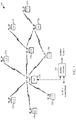
- FIG. 1 illustrates a system 100 in which aspects of the disclosure may be performed.
- any of the wireless stations including the access point 110 and/or the user terminals 120 may be in a neighbor aware network (NAN).
- Wireless stations may exchange fine timing measurement (FTM) information for ranging during a period when the wireless stations are already scheduled to wake up (e.g., during a paging window or data window) and may exchange the FTM information using existing frames (e.g., association frames, trigger frames and/or /polling frames, probe request/probe response frames).
- FTM fine timing measurement
- one of the wireless devices may act as a ranging proxy.
- the system 100 may be, for example, a multiple-access multiple-input multiple-output (MIMO) system 100 with access points and user terminals.
- MIMO multiple-access multiple-input multiple-output
- An access point is generally a fixed station that communicates with the user terminals and may also be referred to as a base station or some other terminology.
- a user terminal may be fixed or mobile and may also be referred to as a mobile station, a wireless device, or some other terminology.
- Access point 110 may communicate with one or more user terminals 120 at any given moment on the downlink and uplink.
- the downlink i.e., forward link
- the uplink i.e., reverse link
- a user terminal may also communicate peer-to-peer with another user terminal.
- a system controller 130 may provide coordination and control for these APs and/or other systems.
- the APs may be managed by the system controller 130, for example, which may handle adjustments to radio frequency power, channels, authentication, and security.
- the system controller 130 may communicate with the APs via a backhaul.
- the APs may also communicate with one another, e.g., directly or indirectly via a wireless or wireline backhaul.
- user terminals 120 capable of communicating via Spatial Division Multiple Access (SDMA)
- the user terminals 120 may also include some user terminals that do not support SDMA.
- an AP 110 may be configured to communicate with both SDMA and non-SDMA user terminals. This approach may conveniently allow older versions of user terminals ("legacy" stations) to remain deployed in an enterprise, extending their useful lifetime, while allowing newer SDMA user terminals to be introduced as deemed appropriate.
- the system 100 employs multiple transmit and multiple receive antennas for data transmission on the downlink and uplink.
- the access point 110 is equipped with N ap antennas and represents the multiple-input (MI) for downlink transmissions and the multiple-output (MO) for uplink transmissions.
- a set of K selected user terminals 120 collectively represents the multiple-output for downlink transmissions and the multiple-input for uplink transmissions.
- MI multiple-input
- MO multiple-output
- K selected user terminals 120 collectively represents the multiple-output for downlink transmissions and the multiple-input for uplink transmissions.
- N ap ⁇ K ⁇ 1 if the data symbol streams for the K user terminals are not multiplexed in code, frequency or time by some means.
- K may be greater than N ap if the data symbol streams can be multiplexed using TDMA technique, different code channels with CDMA, disjoint sets of subbands with OFDM, and so on.
- Each selected user terminal transmits user-specific data to and/or receives user-specific data from the access point.
- each selected user terminal may be equipped with one or multiple antennas (i.e., N ut ⁇ 1).
- the K selected user terminals can have the same or different number of antennas.
- the system 100 may be a time division duplex (TDD) system or a frequency division duplex (FDD) system.
- TDD time division duplex
- FDD frequency division duplex
- MIMO system 100 may also utilize a single carrier or multiple carriers for transmission.
- Each user terminal may be equipped with a single antenna (e.g., in order to keep costs down) or multiple antennas (e.g., where the additional cost can be supported).
- the system 100 may also be a TDMA system if the user terminals 120 share the same frequency channel by dividing transmission/reception into different time slots, each time slot being assigned to different user terminal 120.
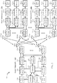
- FIG. 2 illustrates example components of the AP 110 and UT 120 illustrated in FIG. 1 , which may be used to implement aspects of the present disclosure.
- One or more components of the AP 110 and UT 120 may be used to practice aspects of the present disclosure.
- antenna 224, Tx/Rx 222, and/or processors 210, 220, 240, 242, of the AP 110, and/or controller 230 or antenna 252, Tx/Rx 254, processors 260, 270, 288, and 290, and/or controller 280 of UT 120 may be used to perform the operations 700 and 700A described herein and illustrated with reference to FIGs. 7 and 7A , respectively, and operations 900 and 900A described herein and illustrated with reference to FIGs. 9 and 9A, respectively.
- FIG. 2 illustrates a block diagram of access point 110 two user terminals 120m and 120x in a MIMO system 100.
- the access point 110 is equipped with N t antennas 224a through 224ap.
- User terminal 120m is equipped with N ut,m antennas 252ma through 252mu
- user terminal 120x is equipped with N ut,x antennas 252xa through 252xu.
- the access point 110 is a transmitting entity for the downlink and a receiving entity for the uplink.
- Each user terminal 120 is a transmitting entity for the uplink and a receiving entity for the downlink.
- a “transmitting entity” is an independently operated apparatus or device capable of transmitting data via a wireless channel
- a “receiving entity” is an independently operated apparatus or device capable of receiving data via a wireless channel.
- the subscript "dn” denotes the downlink
- the subscript "up” denotes the uplink
- N up user terminals are selected for simultaneous transmission on the uplink
- N dn user terminals are selected for simultaneous transmission on the downlink
- N up may or may not be equal to N dn
- N up and N dn may be static values or can change for each scheduling interval.
- the beam-steering or some other spatial processing technique may be used at the access point and user terminal.
- a transmit (TX) data processor 288 receives traffic data from a data source 286 and control data from a controller 280.
- the controller 280 may be coupled with a memory 282.
- TX data processor 288 processes (e.g., encodes, interleaves, and modulates) the traffic data for the user terminal based on the coding and modulation schemes associated with the rate selected for the user terminal and provides a data symbol stream.
- a TX spatial processor 290 performs spatial processing on the data symbol stream and provides N ut,m transmit symbol streams for the N ut,m antennas.
- Each transmitter unit (TMTR) 254 receives and processes (e.g., converts to analog, amplifies, filters, and frequency upconverts) a respective transmit symbol stream to generate an uplink signal.
- N ut,m transmitter units 254 provide N ut,m the generated uplink signals for transmission from N ut,m antennas 252 to the access point.
- N up user terminals may be scheduled for simultaneous transmission on the uplink.
- Each of these user terminals performs spatial processing on its data symbol stream and transmits its set of transmit symbol streams on the uplink to the access point.
- N ap antennas 224a through 224ap receive the uplink signals from all N up user terminals transmitting on the uplink.
- Each antenna 224 provides a received signal to a respective receiver unit (RCVR) 222.
- Each receiver unit 222 performs processing complementary to that performed by transmitter unit 254 and provides a received symbol stream.
- An RX spatial processor 240 performs receiver spatial processing on the N ap received symbol streams from N ap receiver units 222 and provides N up recovered uplink data symbol streams.
- the receiver spatial processing is performed in accordance with the channel correlation matrix inversion (CCMI), minimum mean square error (MMSE), soft interference cancellation (SIC), or some other technique.
- Each recovered uplink data symbol stream is an estimate of a data symbol stream transmitted by a respective user terminal.
- An RX data processor 242 processes (e.g., demodulates, deinterleaves, and decodes) each recovered uplink data symbol stream in accordance with the rate used for that stream to obtain decoded data.
- the decoded data for each user terminal may be provided to a data sink 244 for storage and/or a controller 230 for further processing.
- the controller 230 may be coupled with a memory 232.
- a TX data processor 210 receives traffic data from a data source 208 for N dn user terminals scheduled for downlink transmission, control data from a controller 230, and possibly other data from a scheduler 234. The various types of data may be sent on different transport channels. TX data processor 210 processes (e.g., encodes, interleaves, and modulates) the traffic data for each user terminal based on the rate selected for that user terminal. TX data processor 210 provides N dn downlink data symbol streams for the N dn user terminals.
- a TX spatial processor 220 performs spatial processing (such as a precoding or beamforming, as described in the present disclosure) on the N dn downlink data symbol streams, and provides N ap transmit symbol streams for the N ap antennas.
- Each transmitter unit 222 receives and processes a respective transmit symbol stream to generate a downlink signal.
- N ap transmitter units 222 providing N ap downlink signals for transmission from N ap antennas 224 to the user terminals.
- the decoded data for each user terminal may be provided to a data sink 272 for storage and/or a controller 280 for further processing.
- N ut,m antennas 252 receive the N ap downlink signals from access point 110.
- Each receiver unit 254 processes a received signal from an associated antenna 252 and provides a received symbol stream.
- An RX spatial processor 260 performs receiver spatial processing on N ut,m received symbol streams from N ut,m receiver units 254 and provides a recovered downlink data symbol stream for the user terminal. The receiver spatial processing is performed in accordance with the CCMI, MMSE or some other technique.
- An RX data processor 270 processes (e.g., demodulates, deinterleaves and decodes) the recovered downlink data symbol stream to obtain decoded data for the user terminal.
- a channel estimator 278 estimates the downlink channel response and provides downlink channel estimates, which may include channel gain estimates, SNR estimates, noise variance and so on.
- a channel estimator 228 estimates the uplink channel response and provides uplink channel estimates.
- Controller 280 for each user terminal typically derives the spatial filter matrix for the user terminal based on the downlink channel response matrix H dn,m for that user terminal.
- Controller 230 derives the spatial filter matrix for the access point based on the effective uplink channel response matrix H up,eff .
- Controller 280 for each user terminal may send feedback information (e.g., the downlink and/or uplink eigenvectors, eigenvalues, SNR estimates, and so on) to the access point.
- Controllers 230 and 280 also control the operation of various processing units at access point 110 and user terminal 120, respectively.
- FIG. 3 illustrates various components that may be utilized in a wireless device 302 that may be employed within the MIMO system 100.
- the wireless device 302 is an example of a device that may be configured to implement the various methods described herein.
- the wireless device may implement operations 700 and 900 illustrated in FIGs. 7 and 9, respectively.
- the wireless device 302 may be an access point 110 or a user terminal 120.
- the wireless device 302 may include a processor 304 which controls operation of the wireless device 302.
- the processor 304 may also be referred to as a central processing unit (CPU).
- Memory 306 which may include both read-only memory (ROM) and random access memory (RAM), provides instructions and data to the processor 304.
- a portion of the memory 306 may also include non-volatile random access memory (NVRAM).
- the processor 304 typically performs logical and arithmetic operations based on program instructions stored within the memory 306.
- the instructions in the memory 306 may be executable to implement the methods described herein.
- the wireless device 302 may also include a housing 308 that may include a transmitter 310 and a receiver 312 to allow transmission and reception of data between the wireless device 302 and a remote node.
- the transmitter 310 and receiver 312 may be combined into a transceiver 314.
- a single or a plurality of transmit antennas 316 may be attached to the housing 308 and electrically coupled to the transceiver 314.
- the wireless device 302 may also include (not shown) multiple transmitters, multiple receivers, and multiple transceivers.
- the wireless device 302 may also include a signal detector 318 that may be used in an effort to detect and quantify the level of signals received by the transceiver 314.
- the signal detector 318 may detect such signals as total energy, energy per subcarrier per symbol, power spectral density and other signals.
- the wireless device 302 may also include a digital signal processor (DSP) 320 for use in processing signals.
- DSP digital signal processor
- the various components of the wireless device 302 may be coupled together by a bus system 322, which may include a power bus, a control signal bus, and a status signal bus in addition to a data bus.
- a bus system 322 may include a power bus, a control signal bus, and a status signal bus in addition to a data bus.
- aspects of the present disclosure provide mechanisms for signaling the use of different resolutions for units of time of different parameters used in procedures involving wireless stations.
- the mechanism may allow for the use of different resolutions for certain parameters in a ranging procedure, such as a fine timing measurement (FTM) ranging procedure.
- FTM fine timing measurement
- the ability to signal different resolutions may allow more accurate timing measurements in certain cases, which may lead to more accurate distance measurements.
- Fine timing measurement generally refers to a ranging protocol (e.g., as defined in the IEEE 802.11mc wireless standard) that measures the distance between two stations (STAs) by measuring round trip travel time (RTT) of messages transmitted between an initiating STA and a responding STA.
- FTM may have a ranging accuracy of around 3 meters.
- a single burst FTM measurement can be accomplished by exchanging 6 frames between the initiating STA and the responding STA.
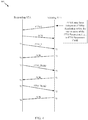
- FIG. 4 is an example call flow 400 illustrating a frame exchange for an example FTM procedure.
- the Initiating STA may send an FTM Request (FTMR) frame to the Responding STA to start the FTM procedure.
- FTMR FTM Request
- the FTMR may include an indication of a resolution of units of time to use for one or more parameters to be used in a ranging procedure performed with a second apparatus (e.g., a wireless node).
- the Responding STA may send an ACK to the Initiating STA.
- the Responding STA may start sending FTM frames (with the transmission times for the FTM frames indicated as t 1 ) which may be received by the Initiating STA at a time indicated as t 2 .
- the Initiating STA may respond with an ACK which may be received by the Responding STA at t 4 .
- these steps may be repeated for each FTM frame (FTM_1, FTM 2, FTM 3) transmitted by the Responding STA, for a total burst exchange of 6 FTM frames.
- the current FTM frame may have the t 1 and the t 4 values from the previous FTM frame embedded (e.g., FTM2 has the t 1 and the t 4 values from the FTM1 exchange).
- the Initiating STA may then use t 1 , t 2 , t 3 , and t 4 (since it already knows t2 and t3, having received an FTM at t2 and having sent an ACK at t3) to estimate the RTT between the Responding STA and the Initiating STA.
- the RTT may be used estimate the range (distance) between the two wireless stations.
- one wireless station may acquire RTT measurements from at least three other wireless stations that may have known 2D locations.
- the wireless station may use the RTT measurements from the other wireless stations to compute its own 2D location. This may increase the number of exchanged FTM frames and reduce network throughput.
- FTM may be used as a way to measure range between two devices and may be included in physical layer (PHY) specifications of devices according to various versions of standards. Examples of such devices include devices capable of high throughput (HT), very high throughput (VHT) and also directional multigigabit (DMG) communications.
- PHY physical layer
- HT high throughput
- VHT very high throughput
- DMG directional multigigabit
- DMG generally refers to operation in frequency bands with a starting frequency above 45 GHz.
- the term DMG may be used in contrast to more frequency-specific terms LB (Low Band at 2.4GHz), HB (High Band at 5GHz), and UB (Ultra Band at 60GHz).
- DMG communications may utilize, for example, a "60 GHz" band from 57 GHz to 66 GHz.
- Some of the principal parameters in certain versions of FTM may have unit resolutions that are optimized for operation in certain frequencies, such as 2.4GHz and 5GHz. Unfortunately, resolutions optimized for one frequency may not be optimal for another frequency. As a result, devices capable of operating in different modes (frequency ranges) may suffer if they are limited to any fixed set of resolutions.
- aspects of the present disclosure provide for signaling to indicate different resolutions for time units of various FTM parameters (contained in a frame) in a manner that may be backwards compatible.
- a mechanism may utilize a format of an existing message structure containing fields for FTM parameters, with a modification of various parameters (e.g., using different resolutions) to enable operation also in DMG mode.
- enabling FTM in devices capable of operating in a DMG mode may open up new options for FTM products. Such options may include, for example, fine range resolution (e.g., on the order of millimeters rather than meters). Further, enhanced throughput and reduced latency of DMG may allow extensive FTM messaging and operation without efficiency reduction. This may allow devices to achieve accurate results for FTM measurements, even when one or more of the devices involved are moving.
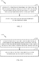
- FIG. 5 illustrates a block diagram of example operations 500 for wireless communications by an apparatus, in accordance with certain aspects of the present disclosure.
- the operations 500 may be performed, for example, by an initiating STA (e.g., the apparatus may be a user terminal 120 or other type wireless station).
- the operations 500 begin, at 502, by generating a first frame providing an indication of a resolution of units of time to use for one or more parameters to be used in a ranging procedure performed with a wireless node.
- the indication may be provided in an FTM parameters field of an FTM request (FTMR) frame.
- the initiating STA may output the first frame for transmission to the wireless node.
- the receiving apparatus in some cases, may reject use of the indicated parameters. If the receiving apparatus rejects in this manner, the initiating device may propose other parameters. In some cases, the receiving apparatus may generate a frame confirming it accepts using the parameters indicated by the initiating apparatus.
- FIG. 6 illustrates a block diagram of example operations 600 for wireless communications by a (different) apparatus, in accordance with certain aspects of the present disclosure.
- the operations 600 may be considered complementary to the operations 500 of FIG. 5 .
- operations 600 may be performed by a responding STA (e.g., an access point 110 or other type wireless station).
- a responding STA e.g., an access point 110 or other type wireless station.
- the operations 600 may begin, at 602, by obtaining a first frame transmitted from a wireless node.
- the responding STA may determine, based on an indication in the first frame, one or more resolutions of units of time to use for one or more parameters to be used in a ranging procedure performed with the wireless node.
- the responding STA performs the ranging procedure according to the determined resolutions.
- the indication of different resolutions for one of more FTM parameters may be provided.
- the indication may be provided in an existing structure (e.g., using an existing frame format).
- a (previously) reserved bit B7 in an FTM parameters set field 700 may be used to indicate a "DMG mode" where one or more FTM parameters use different resolution units (relative to the resolution units used in a "non-DMG mode”).
- This may be advantageous in that such signaling may have no effect on ongoing Wi-Fi Alliance (WFA) Location certification (e.g., this bit is not required to be any certain value).
- WFA Wi-Fi Alliance
- setting this bit may indicate a change in resolution of one or more of the FTM parameters.
- setting the bit may indicate that at least one of at least one of a time of departure (TOD), time of arrival (TOA), maximum TOD error, or maximum TOA error may be expressed in time units of 1ps, rather than lOOps.
- the Min Delta FTM field (that indicates a minimum time between consecutive FTM frames) may be expressed in units of 10 ⁇ s instead of 100us.
- the burst period may be reported in units of 10ms instead of 100ms.
- any combination of one or more of the above-mentioned parameters may have different resolutions. Further, in some cases, more than two sets of resolution units may be signaled (e.g., using more than a single bit).
- the first indication may indicate different resolutions for a first set of one or more parameters (e.g., TOD, TOA, maximum TOD error, or maximum TOA error), while the second indication may indicate different resolutions for a second set of one or more parameters (e.g., a burst period or Min Delta FTM).
- the DMG mode bit may indicate one or more different values are used in the lookup table.
- the burst duration values e.g., in 802.11 Table 8-246 may be set to 32 ⁇ s for entry 0 and 125 ⁇ s for entry 1.
- an FTM burst period may be limited to 100ms, which may limit the accuracy for cases with STA movement.
- using a 10ms burst duration instead of 100ms burst duration may provide sufficient resolution, while maintaining low duty cycle.
- a current FTM minimum burst duration (e.g., 250 us) may correspond to 25 FTM measurements when done in DMG. Aspects of the present disclosure, however, may provide for shorter durations (e.g., higher accuracy using relatively fewer FTM measurements).
- the techniques provided herein may allow for improvement in resolution to the FTM protocol, in a backward-compatible manner, that may help enable FTM operation in DMG PHY and allows for precise measurements (e.g., on the order of mm).
- the proposed changes may have little or no effect on existing (so called "legacy") devices, nor on WFA Location certification of current FTM in 2.4 and 5GHz bands.
- the techniques proposed herein may help align FTM to all bands defined in emerging standards, such as the IEEE 802.11REVmc specification.
- the suggested combination of DMG and FTM may give additional value to both specifications.
- devices may be able to achieve ranging results with higher accuracy than previously possible.
- results may be achieved faster and, in some cases, with less overhead than traditional techniques.
- the methods disclosed herein comprise one or more steps or actions for achieving the described method.
- the method steps and/or actions may be interchanged with one another. In other words, unless a specific order of steps or actions is specified, the order and/or use of specific steps and/or actions may be modified.
- a phrase referring to "at least one of' a list of items refers to any combination of those items, including single members.
- "at least one of: a, b, or c” is intended to cover a, b, c, a-b, a-c, b-c, and a-b-c, as well as any combination with multiples of the same element (e.g., a-a, a-a-a, a-a-b, a-a-c, a-b-b, a-c-c, b-b, b-b-b, b-b-c, c-c, and c-c-c or any other ordering of a, b, and c).
- determining encompasses a wide variety of actions. For example, “determining” may include calculating, computing, processing, deriving, investigating, looking up (e.g., looking up in a table, a database or another data structure), ascertaining and the like. Also, “determining” may include receiving (e.g., receiving information), accessing (e.g., accessing data in a memory) and the like. Also, “determining” may include resolving, selecting, choosing, establishing and the like.
- a device may have an interface to output a frame for transmission.
- a processor may output a frame, via a bus interface, to an RF front end for transmission.
- a device may have an interface to obtain a frame received from another device.
- a processor may obtain (or receive) a frame, via a bus interface, from an RF front end for transmission.
- the various operations of methods described above may be performed by any suitable means capable of performing the corresponding functions.
- the means may include various hardware and/or software component(s) and/or module(s), including, but not limited to a circuit, an application specific integrated circuit (ASIC), or processor.
- ASIC application specific integrated circuit
- operations 500 and 600 illustrated in FIGs. 5 and 6 correspond to means 500A and 600A illustrated in FIGs. 5A and 6A , respectively.
- means for receiving and means for obtaining may be a receiver (e.g., the receiver unit of transceiver 254) and/or an antenna(s) 252 of the user terminal 120 illustrated in FIG. 2 or the receiver (e.g., the receiver unit of transceiver 222) and/or antenna(s) 224 of access point 110 illustrated in FIG. 2 .
- Means for transmitting and means for outputting may be a transmitter (e.g., the transmitter unit of transceiver 254) and/or an antenna(s) 252 of the user terminal 120 illustrated in FIG. 2 or the transmitter (e.g., the transmitter unit of transceiver 222) and/or antenna(s) 224 of access point 110 illustrated in FIG. 2 .
- Means for generating, means for performing, and means for determining may comprise a processing system, which may include one or more processors, such as the RX data processor 270, the TX data processor 288, and/or the controller 280 of the user terminal 120 illustrated in FIG. 2 or the TX data processor 210, RX data processor 242, and/or the controller 230 of the access point 110 illustrated in FIG. 2 .
- processors such as the RX data processor 270, the TX data processor 288, and/or the controller 280 of the user terminal 120 illustrated in FIG. 2 or the TX data processor 210, RX data processor 242, and/or the controller 230 of the access point 110 illustrated in FIG. 2 .
- such means may be implemented by processing systems configured to perform the corresponding functions by implementing various algorithms (e.g., in hardware or by executing software instructions) described above. For example, an algorithm for determining a period that at least one second apparatus is scheduled to be awake, an algorithm for generating a first frame for transmission to the second apparatus during the period, an algorithm for outputting the first frame for transmission, an algorithm for obtaining a second frame in response to the first frame, an algorithm for determining ranging information based on a time difference between transmission of the first frame and receipt of the second frame, an algorithm for generate a third frame including the ranging information, and an algorithm for outputting the third frame for transmission.
- various algorithms e.g., in hardware or by executing software instructions
- an algorithm for determining a period to awake from a low power state an algorithm for obtaining a first frame from a second apparatus during the period, an algorithm for generating a second frame for transmission to the second apparatus in response to the first frame, an algorithm for outputting the second frame for transmission to the second apparatus, an algorithm for obtaining a third frame comprising ranging information, determined by the second apparatus, based on a time difference between transmission of the first frame and receipt of the second frame, and an algorithm for determining a relative location of the second apparatus to the apparatus based on a third frame.
- DSP digital signal processor
- ASIC application specific integrated circuit
- FPGA field programmable gate array
- PLD programmable logic device
- a general-purpose processor may be a microprocessor, but in the alternative, the processor may be any commercially available processor, controller, microcontroller, or state machine.
- a processor may also be implemented as a combination of computing devices, e.g., a combination of a DSP and a microprocessor, a plurality of microprocessors, one or more microprocessors in conjunction with a DSP core, or any other such configuration.
- an example hardware configuration may comprise a processing system in a wireless node.
- the processing system may be implemented with a bus architecture.
- the bus may include any number of interconnecting buses and bridges depending on the specific application of the processing system and the overall design constraints.
- the bus may link together various circuits including a processor, machine-readable media, and a bus interface.
- the bus interface may be used to connect a network adapter, among other things, to the processing system via the bus.
- the network adapter may be used to implement the signal processing functions of the PHY layer.
- a user interface e.g., keypad, display, mouse, joystick, etc.
- the bus may also link various other circuits such as timing sources, peripherals, voltage regulators, power management circuits, and the like, which are well known in the art, and therefore, will not be described any further.
- the processor may be implemented with one or more general-purpose and/or special-purpose processors. Examples include microprocessors, microcontrollers, DSP processors, and other circuitry that can execute software. Those skilled in the art will recognize how best to implement the described functionality for the processing system depending on the particular application and the overall design constraints imposed on the overall system.
- the functions may be stored or transmitted over as one or more instructions or code on a computer-readable medium.
- Software shall be construed broadly to mean instructions, data, or any combination thereof, whether referred to as software, firmware, middleware, microcode, hardware description language, or otherwise.
- Computer-readable media include both computer storage media and communication media including any medium that facilitates transfer of a computer program from one place to another.
- the processor may be responsible for managing the bus and general processing, including the execution of software modules stored on the machine-readable storage media.
- a computer-readable storage medium may be coupled to a processor such that the processor can read information from, and write information to, the storage medium. In the alternative, the storage medium may be integral to the processor.
- the machine-readable media may include a transmission line, a carrier wave modulated by data, and/or a computer readable storage medium with instructions stored thereon separate from the wireless node, all of which may be accessed by the processor through the bus interface.
- the machine-readable media, or any portion thereof may be integrated into the processor, such as the case may be with cache and/or general register files.
- machine-readable storage media may include, by way of example, RAM (Random Access Memory), flash memory, ROM (Read Only Memory), PROM (Programmable Read-Only Memory), EPROM (Erasable Programmable Read-Only Memory), EEPROM (Electrically Erasable Programmable Read-Only Memory), registers, magnetic disks, optical disks, hard drives, or any other suitable storage medium, or any combination thereof.
- RAM Random Access Memory
- ROM Read Only Memory
- PROM PROM
- EPROM Erasable Programmable Read-Only Memory
- EEPROM Electrical Erasable Programmable Read-Only Memory
- registers magnetic disks, optical disks, hard drives, or any other suitable storage medium, or any combination thereof.
- the machine-readable media may be embodied in a computer-program product.
- a software module may comprise a single instruction, or many instructions, and may be distributed over several different code segments, among different programs, and across multiple storage media.
- the computer-readable media may comprise a number of software modules.
- the software modules include instructions that, when executed by an apparatus such as a processor, cause the processing system to perform various functions.
- the software modules may include a transmission module and a receiving module. Each software module may reside in a single storage device or be distributed across multiple storage devices.
- a software module may be loaded into RAM from a hard drive when a triggering event occurs.
- the processor may load some of the instructions into cache to increase access speed.
- One or more cache lines may then be loaded into a general register file for execution by the processor.
- any connection is properly termed a computer-readable medium.
- the software is transmitted from a website, server, or other remote source using a coaxial cable, fiber optic cable, twisted pair, digital subscriber line (DSL), or wireless technologies such as infrared (IR), radio, and microwave
- the coaxial cable, fiber optic cable, twisted pair, DSL, or wireless technologies such as infrared, radio, and microwave are included in the definition of medium.
- Disk and disc include compact disc (CD), laser disc, optical disc, digital versatile disc (DVD), floppy disk, and Blu-ray® disc where disks usually reproduce data magnetically, while discs reproduce data optically with lasers.
- computer-readable media may comprise non-transitory computer-readable media (e.g., tangible media).
- computer-readable media may comprise transitory computer-readable media (e.g., a signal). Combinations of the above should also be included within the scope of computer-readable media.
- certain aspects may comprise a computer program product for performing the operations presented herein.
- a computer program product may comprise a computer-readable medium having instructions stored (and/or encoded) thereon, the instructions being executable by one or more processors to perform the operations described herein. For example, instructions for determining a period that at least one second apparatus is scheduled to be awake, instructions for generating a first frame for transmission to the second apparatus during the period, instructions for outputting the first frame for transmission, instructions for obtaining a second frame in response to the first frame, instructions for determining ranging information based on a time difference between transmission of the first frame and receipt of the second frame, instructions for generate a third frame including the ranging information, and instructions for outputting the third frame for transmission.
- instructions for determining a period to awake from a low power state instructions for obtaining a first frame from a second apparatus during the period, instructions for generating a second frame for transmission to the second apparatus in response to the first frame, instructions for outputting the second frame for transmission to the second apparatus, instructions for obtaining a third frame comprising ranging information, determined by the second apparatus, based on a time difference between transmission of the first frame and receipt of the second frame, and instructions for determining a relative location of the second apparatus to the first apparatus based on a third frame.
- modules and/or other appropriate means for performing the methods and techniques described herein can be downloaded and/or otherwise obtained by a user terminal an/dor base station as applicable.
- a user terminal can be coupled to a server to facilitate the transfer of means for performing the methods described herein.
- various methods described herein can be provided via storage means (e.g., RAM, ROM, a physical storage medium such as a compact disc (CD) or floppy disk, etc.), such that a user terminal and/or base station can obtain the various methods upon coupling or providing the storage means to the device.
- storage means e.g., RAM, ROM, a physical storage medium such as a compact disc (CD) or floppy disk, etc.
- CD compact disc
- floppy disk etc.
- any other suitable technique for providing the methods and techniques described herein to a device can be utilized.
Landscapes
- Engineering & Computer Science (AREA)
- Radar, Positioning & Navigation (AREA)
- Remote Sensing (AREA)
- Computer Networks & Wireless Communication (AREA)
- Physics & Mathematics (AREA)
- General Physics & Mathematics (AREA)
- Signal Processing (AREA)
- Health & Medical Sciences (AREA)
- Cardiology (AREA)
- General Health & Medical Sciences (AREA)
- Mobile Radio Communication Systems (AREA)
- Radar Systems Or Details Thereof (AREA)
Applications Claiming Priority (3)
| Application Number | Priority Date | Filing Date | Title |
|---|---|---|---|
| US201562167145P | 2015-05-27 | 2015-05-27 | |
| US15/088,108 US10187817B2 (en) | 2015-05-27 | 2016-03-31 | Measuring distance in wireless devices |
| PCT/US2016/025556 WO2016190960A1 (en) | 2015-05-27 | 2016-04-01 | Measuring distance in wireless devices |
Publications (2)
| Publication Number | Publication Date |
|---|---|
| EP3304122A1 EP3304122A1 (en) | 2018-04-11 |
| EP3304122B1 true EP3304122B1 (en) | 2021-07-21 |
Family
ID=55754449
Family Applications (1)
| Application Number | Title | Priority Date | Filing Date |
|---|---|---|---|
| EP16716771.7A Active EP3304122B1 (en) | 2015-05-27 | 2016-04-01 | Measuring distance in wireless devices |
Country Status (9)
| Country | Link |
|---|---|
| US (2) | US10187817B2 (enExample) |
| EP (1) | EP3304122B1 (enExample) |
| JP (1) | JP6655100B2 (enExample) |
| KR (1) | KR20180012272A (enExample) |
| CN (1) | CN107710013B (enExample) |
| BR (1) | BR112017025155A2 (enExample) |
| TW (1) | TWI713513B (enExample) |
| UY (1) | UY36689A (enExample) |
| WO (1) | WO2016190960A1 (enExample) |
Families Citing this family (21)
| Publication number | Priority date | Publication date | Assignee | Title |
|---|---|---|---|---|
| US10187817B2 (en) | 2015-05-27 | 2019-01-22 | Qualcomm Incorporated | Measuring distance in wireless devices |
| US9907042B2 (en) * | 2015-06-15 | 2018-02-27 | Intel IP Corporation | Apparatus, system and method of determining a time synchronization function (TSF) based on fine time measurement (FTM) messages |
| CN106936559B (zh) * | 2015-12-29 | 2020-01-31 | 华为技术有限公司 | 一种精细时间测量ftm方法和通信设备 |
| US10631187B1 (en) * | 2016-08-30 | 2020-04-21 | Marvell International Ltd. | Method and apparatus for ranging |
| US10158443B1 (en) | 2016-09-02 | 2018-12-18 | Marvell International Ltd. | Methods and apparatus for fine timing measurement with frequency domain processing |
| US10120642B2 (en) | 2016-12-13 | 2018-11-06 | EVA Automation, Inc. | Software-based wireless coordination of audio playback |
| US10901684B2 (en) | 2016-12-13 | 2021-01-26 | EVA Automation, Inc. | Wireless inter-room coordination of audio playback |
| US10255032B2 (en) | 2016-12-13 | 2019-04-09 | EVA Automation, Inc. | Wireless coordination of audio sources |
| US10908274B2 (en) * | 2019-01-11 | 2021-02-02 | Samsung Electronics Co... Ltd. | Framework and methods to acknowledge the ranging configuration for IEEE 802.15.4Z |
| US11212345B2 (en) * | 2019-03-08 | 2021-12-28 | Samsung Electronics Co., Ltd. | Framework and methods to control exchange of ranging result |
| US11304031B2 (en) | 2019-10-10 | 2022-04-12 | Samsung Electronics Co., Ltd. | Wireless local area network system, method of transmitting distance information and measuring distance of wireless local area network system |
| US11109373B2 (en) * | 2019-10-18 | 2021-08-31 | Bae Systems Information And Electronic Systems Integration Inc. | Multiple message single timeslot Link 16 relay transmission |
| US10945231B1 (en) | 2020-03-05 | 2021-03-09 | Cisco Technology, Inc. | Regulation of airtime for fine timing measurement requests |
| CN113630865A (zh) * | 2020-05-09 | 2021-11-09 | 北京金坤科创技术有限公司 | 一种多基站多终端定位方法 |
| CN114363943B (zh) * | 2020-10-13 | 2024-09-24 | 华为技术有限公司 | 用于确定传输时延的方法和电子设备 |
| US11856435B2 (en) | 2021-03-31 | 2023-12-26 | Hewlett Packard Enterprise Development Lp | Handling fine timing measurement requests |
| US20220338141A1 (en) * | 2021-04-14 | 2022-10-20 | Qualcomm Incorporated | Location protocol with adaptive ranging trigger |
| US12317206B2 (en) | 2021-06-17 | 2025-05-27 | Electronics And Telecommunications Research Institute | Method and apparatus for timing adjustment in mobile communication system |
| US12356280B2 (en) * | 2021-08-31 | 2025-07-08 | Apple Inc. | Techniques for synchronizing ultra-wide band communications |
| US12085659B2 (en) | 2021-12-03 | 2024-09-10 | Hewlett Packard Enterprise Development Lp | Ranging by a network device during a beacon interval |
| US12101685B2 (en) | 2021-12-03 | 2024-09-24 | Hewlett Packard Enterprise Development Lp | Coordinated ranging between access points in a network |
Family Cites Families (20)
| Publication number | Priority date | Publication date | Assignee | Title |
|---|---|---|---|---|
| US7539134B1 (en) * | 1999-11-16 | 2009-05-26 | Broadcom Corporation | High speed flow control methodology |
| US7908147B2 (en) * | 2006-04-24 | 2011-03-15 | Seiko Epson Corporation | Delay profiling in a communication system |
| US8879573B2 (en) * | 2006-12-01 | 2014-11-04 | Microsoft Corporation | Media access control (MAC) protocol for cognitive wireless networks |
| TWI497933B (zh) * | 2007-08-13 | 2015-08-21 | Interdigital Tech Corp | 與間歇流量關聯的無線資源開銷降低方法及裝置 |
| US8199047B2 (en) * | 2010-03-09 | 2012-06-12 | Ensco, Inc. | High-precision radio frequency ranging system |
| JP5662779B2 (ja) * | 2010-12-07 | 2015-02-04 | 株式会社日立製作所 | 通信システム及びノード装置 |
| US20120163261A1 (en) * | 2010-12-23 | 2012-06-28 | Texas Instruments Incorporated | Timing measurements between wireless stations with reduced power consumption |
| EP2700196B1 (en) * | 2011-04-18 | 2015-01-28 | Telefonaktiebolaget LM Ericsson (PUBL) | Method and apparatus for quality of service monitoring of services in a communication network |
| CN103782649B (zh) * | 2011-09-13 | 2018-08-24 | 皇家飞利浦有限公司 | 通过对接系统和通用网络设备驱动器的无线lan连接切换 |
| US20140073352A1 (en) * | 2012-09-11 | 2014-03-13 | Qualcomm Incorporated | Method for precise location determination |
| US9223003B2 (en) | 2012-12-18 | 2015-12-29 | Intel Corporation | Differentiated station location |
| US9226260B2 (en) | 2013-05-10 | 2015-12-29 | Intel Corporation | Initiator-conditioned fine timing measurement service request |
| US9699052B2 (en) | 2013-05-30 | 2017-07-04 | Qualcomm Incorporated | Methods and systems for enhanced round trip time (RTT) exchange |
| US9591493B2 (en) * | 2013-08-19 | 2017-03-07 | Broadcom Corporation | Wireless communication fine timing measurement PHY parameter control and negotiation |
| US10484814B2 (en) * | 2014-02-25 | 2019-11-19 | Mediatek Inc. | Direction finding and FTM positioning in wireless local area networks |
| US9854468B2 (en) * | 2014-03-05 | 2017-12-26 | Marvell World Trade Ltd. | Method and apparatus for estimating distance between network devices in a wireless network |
| US10225338B1 (en) * | 2014-04-15 | 2019-03-05 | Marvell International Ltd. | Peer to peer ranging exchange |
| US10687309B2 (en) * | 2015-05-08 | 2020-06-16 | Texas Instruments Incorporated | Enhanced broadcast transmission in unslotted channel hopping medium access control |
| US10187817B2 (en) | 2015-05-27 | 2019-01-22 | Qualcomm Incorporated | Measuring distance in wireless devices |
| US10447452B2 (en) | 2015-07-13 | 2019-10-15 | Advanced Micro Devices, Inc. | Hardware controlled receive response generation |
-
2016
- 2016-03-31 US US15/088,108 patent/US10187817B2/en active Active
- 2016-04-01 WO PCT/US2016/025556 patent/WO2016190960A1/en not_active Ceased
- 2016-04-01 KR KR1020177034171A patent/KR20180012272A/ko not_active Ceased
- 2016-04-01 BR BR112017025155A patent/BR112017025155A2/pt not_active IP Right Cessation
- 2016-04-01 JP JP2017559660A patent/JP6655100B2/ja active Active
- 2016-04-01 EP EP16716771.7A patent/EP3304122B1/en active Active
- 2016-04-01 CN CN201680030224.4A patent/CN107710013B/zh active Active
- 2016-04-06 TW TW105110780A patent/TWI713513B/zh not_active IP Right Cessation
- 2016-05-27 UY UY0001036689A patent/UY36689A/es active IP Right Grant
-
2018
- 2018-10-22 US US16/166,998 patent/US10771999B2/en active Active
Non-Patent Citations (1)
| Title |
|---|
| None * |
Also Published As
| Publication number | Publication date |
|---|---|
| US10771999B2 (en) | 2020-09-08 |
| CN107710013A (zh) | 2018-02-16 |
| CN107710013B (zh) | 2021-09-10 |
| BR112017025155A2 (pt) | 2018-08-07 |
| TWI713513B (zh) | 2020-12-21 |
| WO2016190960A1 (en) | 2016-12-01 |
| US10187817B2 (en) | 2019-01-22 |
| TW201711493A (zh) | 2017-03-16 |
| US20160353306A1 (en) | 2016-12-01 |
| JP2018518895A (ja) | 2018-07-12 |
| US20190059014A1 (en) | 2019-02-21 |
| KR20180012272A (ko) | 2018-02-05 |
| JP6655100B2 (ja) | 2020-02-26 |
| UY36689A (es) | 2016-11-30 |
| EP3304122A1 (en) | 2018-04-11 |
Similar Documents
| Publication | Publication Date | Title |
|---|---|---|
| EP3304122B1 (en) | Measuring distance in wireless devices | |
| US20240396604A1 (en) | Coordinated beamforming (cobf) protocol for unmanaged networks | |
| US10111132B2 (en) | Methods and apparatus for channel state information sounding and feedback | |
| EP3257305B1 (en) | Efficient ranging | |
| US11051297B2 (en) | Spatial reuse and transmit opportunity duration representation | |
| CN106664704A (zh) | 用于ul mimo/ofdma传输的信令技术 | |
| US20170041953A1 (en) | Bandwidth dependent carrier sensing for ofdma | |
| US20170325254A1 (en) | Default spatial reuse modes | |
| EP3092849B1 (en) | Bandwidth indication in a frame | |
| US12245082B2 (en) | Flexible negotiation of parameters in setup exchanges for wireless communication sessions | |
| KR101518150B1 (ko) | Tv 화이트 스페이스 디바이스들을 위한 전력 제어 | |
| US10191798B2 (en) | Extended interframe space (EIFS) exemptions | |
| US20170223741A1 (en) | Efficient clear channel assessment (cca) with request-to-send (rts) frame and clear-to-send (cts) frame | |
| US12160294B2 (en) | Asymmetric coordinated beamforming | |
| US20150124747A1 (en) | Aid switch negotiation |
Legal Events
| Date | Code | Title | Description |
|---|---|---|---|
| STAA | Information on the status of an ep patent application or granted ep patent |
Free format text: STATUS: THE INTERNATIONAL PUBLICATION HAS BEEN MADE |
|
| PUAI | Public reference made under article 153(3) epc to a published international application that has entered the european phase |
Free format text: ORIGINAL CODE: 0009012 |
|
| STAA | Information on the status of an ep patent application or granted ep patent |
Free format text: STATUS: REQUEST FOR EXAMINATION WAS MADE |
|
| 17P | Request for examination filed |
Effective date: 20171122 |
|
| AK | Designated contracting states |
Kind code of ref document: A1 Designated state(s): AL AT BE BG CH CY CZ DE DK EE ES FI FR GB GR HR HU IE IS IT LI LT LU LV MC MK MT NL NO PL PT RO RS SE SI SK SM TR |
|
| AX | Request for extension of the european patent |
Extension state: BA ME |
|
| DAV | Request for validation of the european patent (deleted) | ||
| DAX | Request for extension of the european patent (deleted) | ||
| STAA | Information on the status of an ep patent application or granted ep patent |
Free format text: STATUS: EXAMINATION IS IN PROGRESS |
|
| 17Q | First examination report despatched |
Effective date: 20190104 |
|
| REG | Reference to a national code |
Ref country code: DE Ref legal event code: R079 Ref document number: 602016060878 Country of ref document: DE Free format text: PREVIOUS MAIN CLASS: G01S0013760000 Ipc: G01S0005020000 |
|
| RIC1 | Information provided on ipc code assigned before grant |
Ipc: G01S 5/02 20100101ALI20201216BHEP Ipc: H04W 64/00 20090101ALI20201216BHEP Ipc: H04W 56/00 20090101AFI20201216BHEP Ipc: G01S 13/76 20060101ALI20201216BHEP |
|
| RIC1 | Information provided on ipc code assigned before grant |
Ipc: H04W 64/00 20090101ALI20201218BHEP Ipc: G01S 5/02 20100101AFI20201218BHEP Ipc: H04W 56/00 20090101ALI20201218BHEP Ipc: G01S 13/76 20060101ALI20201218BHEP Ipc: G01S 11/02 20100101ALI20201218BHEP |
|
| GRAP | Despatch of communication of intention to grant a patent |
Free format text: ORIGINAL CODE: EPIDOSNIGR1 |
|
| STAA | Information on the status of an ep patent application or granted ep patent |
Free format text: STATUS: GRANT OF PATENT IS INTENDED |
|
| INTG | Intention to grant announced |
Effective date: 20210205 |
|
| GRAS | Grant fee paid |
Free format text: ORIGINAL CODE: EPIDOSNIGR3 |
|
| GRAA | (expected) grant |
Free format text: ORIGINAL CODE: 0009210 |
|
| STAA | Information on the status of an ep patent application or granted ep patent |
Free format text: STATUS: THE PATENT HAS BEEN GRANTED |
|
| AK | Designated contracting states |
Kind code of ref document: B1 Designated state(s): AL AT BE BG CH CY CZ DE DK EE ES FI FR GB GR HR HU IE IS IT LI LT LU LV MC MK MT NL NO PL PT RO RS SE SI SK SM TR |
|
| REG | Reference to a national code |
Ref country code: GB Ref legal event code: FG4D |
|
| REG | Reference to a national code |
Ref country code: CH Ref legal event code: EP |
|
| REG | Reference to a national code |
Ref country code: DE Ref legal event code: R096 Ref document number: 602016060878 Country of ref document: DE |
|
| REG | Reference to a national code |
Ref country code: AT Ref legal event code: REF Ref document number: 1413069 Country of ref document: AT Kind code of ref document: T Effective date: 20210815 |
|
| REG | Reference to a national code |
Ref country code: IE Ref legal event code: FG4D |
|
| REG | Reference to a national code |
Ref country code: LT Ref legal event code: MG9D |
|
| REG | Reference to a national code |
Ref country code: NL Ref legal event code: MP Effective date: 20210721 |
|
| REG | Reference to a national code |
Ref country code: AT Ref legal event code: MK05 Ref document number: 1413069 Country of ref document: AT Kind code of ref document: T Effective date: 20210721 |
|
| PG25 | Lapsed in a contracting state [announced via postgrant information from national office to epo] |
Ref country code: RS Free format text: LAPSE BECAUSE OF FAILURE TO SUBMIT A TRANSLATION OF THE DESCRIPTION OR TO PAY THE FEE WITHIN THE PRESCRIBED TIME-LIMIT Effective date: 20210721 Ref country code: SE Free format text: LAPSE BECAUSE OF FAILURE TO SUBMIT A TRANSLATION OF THE DESCRIPTION OR TO PAY THE FEE WITHIN THE PRESCRIBED TIME-LIMIT Effective date: 20210721 Ref country code: AT Free format text: LAPSE BECAUSE OF FAILURE TO SUBMIT A TRANSLATION OF THE DESCRIPTION OR TO PAY THE FEE WITHIN THE PRESCRIBED TIME-LIMIT Effective date: 20210721 Ref country code: BG Free format text: LAPSE BECAUSE OF FAILURE TO SUBMIT A TRANSLATION OF THE DESCRIPTION OR TO PAY THE FEE WITHIN THE PRESCRIBED TIME-LIMIT Effective date: 20211021 Ref country code: LT Free format text: LAPSE BECAUSE OF FAILURE TO SUBMIT A TRANSLATION OF THE DESCRIPTION OR TO PAY THE FEE WITHIN THE PRESCRIBED TIME-LIMIT Effective date: 20210721 Ref country code: NO Free format text: LAPSE BECAUSE OF FAILURE TO SUBMIT A TRANSLATION OF THE DESCRIPTION OR TO PAY THE FEE WITHIN THE PRESCRIBED TIME-LIMIT Effective date: 20211021 Ref country code: PT Free format text: LAPSE BECAUSE OF FAILURE TO SUBMIT A TRANSLATION OF THE DESCRIPTION OR TO PAY THE FEE WITHIN THE PRESCRIBED TIME-LIMIT Effective date: 20211122 Ref country code: NL Free format text: LAPSE BECAUSE OF FAILURE TO SUBMIT A TRANSLATION OF THE DESCRIPTION OR TO PAY THE FEE WITHIN THE PRESCRIBED TIME-LIMIT Effective date: 20210721 Ref country code: FI Free format text: LAPSE BECAUSE OF FAILURE TO SUBMIT A TRANSLATION OF THE DESCRIPTION OR TO PAY THE FEE WITHIN THE PRESCRIBED TIME-LIMIT Effective date: 20210721 Ref country code: ES Free format text: LAPSE BECAUSE OF FAILURE TO SUBMIT A TRANSLATION OF THE DESCRIPTION OR TO PAY THE FEE WITHIN THE PRESCRIBED TIME-LIMIT Effective date: 20210721 Ref country code: HR Free format text: LAPSE BECAUSE OF FAILURE TO SUBMIT A TRANSLATION OF THE DESCRIPTION OR TO PAY THE FEE WITHIN THE PRESCRIBED TIME-LIMIT Effective date: 20210721 |
|
| PG25 | Lapsed in a contracting state [announced via postgrant information from national office to epo] |
Ref country code: PL Free format text: LAPSE BECAUSE OF FAILURE TO SUBMIT A TRANSLATION OF THE DESCRIPTION OR TO PAY THE FEE WITHIN THE PRESCRIBED TIME-LIMIT Effective date: 20210721 Ref country code: LV Free format text: LAPSE BECAUSE OF FAILURE TO SUBMIT A TRANSLATION OF THE DESCRIPTION OR TO PAY THE FEE WITHIN THE PRESCRIBED TIME-LIMIT Effective date: 20210721 Ref country code: GR Free format text: LAPSE BECAUSE OF FAILURE TO SUBMIT A TRANSLATION OF THE DESCRIPTION OR TO PAY THE FEE WITHIN THE PRESCRIBED TIME-LIMIT Effective date: 20211022 |
|
| REG | Reference to a national code |
Ref country code: DE Ref legal event code: R097 Ref document number: 602016060878 Country of ref document: DE |
|
| PG25 | Lapsed in a contracting state [announced via postgrant information from national office to epo] |
Ref country code: DK Free format text: LAPSE BECAUSE OF FAILURE TO SUBMIT A TRANSLATION OF THE DESCRIPTION OR TO PAY THE FEE WITHIN THE PRESCRIBED TIME-LIMIT Effective date: 20210721 |
|
| PLBE | No opposition filed within time limit |
Free format text: ORIGINAL CODE: 0009261 |
|
| STAA | Information on the status of an ep patent application or granted ep patent |
Free format text: STATUS: NO OPPOSITION FILED WITHIN TIME LIMIT |
|
| PG25 | Lapsed in a contracting state [announced via postgrant information from national office to epo] |
Ref country code: SM Free format text: LAPSE BECAUSE OF FAILURE TO SUBMIT A TRANSLATION OF THE DESCRIPTION OR TO PAY THE FEE WITHIN THE PRESCRIBED TIME-LIMIT Effective date: 20210721 Ref country code: SK Free format text: LAPSE BECAUSE OF FAILURE TO SUBMIT A TRANSLATION OF THE DESCRIPTION OR TO PAY THE FEE WITHIN THE PRESCRIBED TIME-LIMIT Effective date: 20210721 Ref country code: RO Free format text: LAPSE BECAUSE OF FAILURE TO SUBMIT A TRANSLATION OF THE DESCRIPTION OR TO PAY THE FEE WITHIN THE PRESCRIBED TIME-LIMIT Effective date: 20210721 Ref country code: EE Free format text: LAPSE BECAUSE OF FAILURE TO SUBMIT A TRANSLATION OF THE DESCRIPTION OR TO PAY THE FEE WITHIN THE PRESCRIBED TIME-LIMIT Effective date: 20210721 Ref country code: CZ Free format text: LAPSE BECAUSE OF FAILURE TO SUBMIT A TRANSLATION OF THE DESCRIPTION OR TO PAY THE FEE WITHIN THE PRESCRIBED TIME-LIMIT Effective date: 20210721 Ref country code: AL Free format text: LAPSE BECAUSE OF FAILURE TO SUBMIT A TRANSLATION OF THE DESCRIPTION OR TO PAY THE FEE WITHIN THE PRESCRIBED TIME-LIMIT Effective date: 20210721 |
|
| 26N | No opposition filed |
Effective date: 20220422 |
|
| PG25 | Lapsed in a contracting state [announced via postgrant information from national office to epo] |
Ref country code: IT Free format text: LAPSE BECAUSE OF FAILURE TO SUBMIT A TRANSLATION OF THE DESCRIPTION OR TO PAY THE FEE WITHIN THE PRESCRIBED TIME-LIMIT Effective date: 20210721 |
|
| REG | Reference to a national code |
Ref country code: CH Ref legal event code: PL |
|
| REG | Reference to a national code |
Ref country code: BE Ref legal event code: MM Effective date: 20220430 |
|
| PG25 | Lapsed in a contracting state [announced via postgrant information from national office to epo] |
Ref country code: MC Free format text: LAPSE BECAUSE OF FAILURE TO SUBMIT A TRANSLATION OF THE DESCRIPTION OR TO PAY THE FEE WITHIN THE PRESCRIBED TIME-LIMIT Effective date: 20210721 Ref country code: LU Free format text: LAPSE BECAUSE OF NON-PAYMENT OF DUE FEES Effective date: 20220401 Ref country code: LI Free format text: LAPSE BECAUSE OF NON-PAYMENT OF DUE FEES Effective date: 20220430 Ref country code: CH Free format text: LAPSE BECAUSE OF NON-PAYMENT OF DUE FEES Effective date: 20220430 |
|
| PG25 | Lapsed in a contracting state [announced via postgrant information from national office to epo] |
Ref country code: BE Free format text: LAPSE BECAUSE OF NON-PAYMENT OF DUE FEES Effective date: 20220430 |
|
| PG25 | Lapsed in a contracting state [announced via postgrant information from national office to epo] |
Ref country code: IE Free format text: LAPSE BECAUSE OF NON-PAYMENT OF DUE FEES Effective date: 20220401 |
|
| PG25 | Lapsed in a contracting state [announced via postgrant information from national office to epo] |
Ref country code: HU Free format text: LAPSE BECAUSE OF FAILURE TO SUBMIT A TRANSLATION OF THE DESCRIPTION OR TO PAY THE FEE WITHIN THE PRESCRIBED TIME-LIMIT; INVALID AB INITIO Effective date: 20160401 |
|
| PG25 | Lapsed in a contracting state [announced via postgrant information from national office to epo] |
Ref country code: MK Free format text: LAPSE BECAUSE OF FAILURE TO SUBMIT A TRANSLATION OF THE DESCRIPTION OR TO PAY THE FEE WITHIN THE PRESCRIBED TIME-LIMIT Effective date: 20210721 Ref country code: CY Free format text: LAPSE BECAUSE OF FAILURE TO SUBMIT A TRANSLATION OF THE DESCRIPTION OR TO PAY THE FEE WITHIN THE PRESCRIBED TIME-LIMIT Effective date: 20210721 |
|
| PG25 | Lapsed in a contracting state [announced via postgrant information from national office to epo] |
Ref country code: TR Free format text: LAPSE BECAUSE OF FAILURE TO SUBMIT A TRANSLATION OF THE DESCRIPTION OR TO PAY THE FEE WITHIN THE PRESCRIBED TIME-LIMIT Effective date: 20210721 |
|
| PG25 | Lapsed in a contracting state [announced via postgrant information from national office to epo] |
Ref country code: MT Free format text: LAPSE BECAUSE OF FAILURE TO SUBMIT A TRANSLATION OF THE DESCRIPTION OR TO PAY THE FEE WITHIN THE PRESCRIBED TIME-LIMIT Effective date: 20210721 |
|
| PGFP | Annual fee paid to national office [announced via postgrant information from national office to epo] |
Ref country code: FR Payment date: 20250319 Year of fee payment: 10 |
|
| PGFP | Annual fee paid to national office [announced via postgrant information from national office to epo] |
Ref country code: GB Payment date: 20250313 Year of fee payment: 10 |
|
| PGFP | Annual fee paid to national office [announced via postgrant information from national office to epo] |
Ref country code: DE Payment date: 20250317 Year of fee payment: 10 |