EP3303656B1 - Anodenklemmanordnung und verwendung solch einer anordnung - Google Patents
Anodenklemmanordnung und verwendung solch einer anordnung Download PDFInfo
- Publication number
- EP3303656B1 EP3303656B1 EP16802615.1A EP16802615A EP3303656B1 EP 3303656 B1 EP3303656 B1 EP 3303656B1 EP 16802615 A EP16802615 A EP 16802615A EP 3303656 B1 EP3303656 B1 EP 3303656B1
- Authority
- EP
- European Patent Office
- Prior art keywords
- legs
- anode
- assembly
- clamp
- rotation axis
- Prior art date
- Legal status (The legal status is an assumption and is not a legal conclusion. Google has not performed a legal analysis and makes no representation as to the accuracy of the status listed.)
- Not-in-force
Links
- 210000002414 leg Anatomy 0.000 claims description 75
- 229910000831 Steel Inorganic materials 0.000 claims description 19
- 239000010959 steel Substances 0.000 claims description 19
- 229910052751 metal Inorganic materials 0.000 claims description 17
- 239000002184 metal Substances 0.000 claims description 17
- 229910052782 aluminium Inorganic materials 0.000 claims description 5
- XAGFODPZIPBFFR-UHFFFAOYSA-N aluminium Chemical compound [Al] XAGFODPZIPBFFR-UHFFFAOYSA-N 0.000 claims description 5
- 238000005260 corrosion Methods 0.000 claims description 5
- 230000007797 corrosion Effects 0.000 claims description 5
- 210000000629 knee joint Anatomy 0.000 claims description 4
- 238000010276 construction Methods 0.000 description 8
- 239000000463 material Substances 0.000 description 6
- 230000003213 activating effect Effects 0.000 description 4
- 238000003466 welding Methods 0.000 description 4
- 239000004411 aluminium Substances 0.000 description 2
- UQDJGEHQDNVPGU-UHFFFAOYSA-N serine phosphoethanolamine Chemical compound [NH3+]CCOP([O-])(=O)OCC([NH3+])C([O-])=O UQDJGEHQDNVPGU-UHFFFAOYSA-N 0.000 description 2
- 230000009286 beneficial effect Effects 0.000 description 1
- 230000009189 diving Effects 0.000 description 1
- 238000004519 manufacturing process Methods 0.000 description 1
- 150000002739 metals Chemical class 0.000 description 1
- 238000000034 method Methods 0.000 description 1
Images


Classifications
-
- C—CHEMISTRY; METALLURGY
- C23—COATING METALLIC MATERIAL; COATING MATERIAL WITH METALLIC MATERIAL; CHEMICAL SURFACE TREATMENT; DIFFUSION TREATMENT OF METALLIC MATERIAL; COATING BY VACUUM EVAPORATION, BY SPUTTERING, BY ION IMPLANTATION OR BY CHEMICAL VAPOUR DEPOSITION, IN GENERAL; INHIBITING CORROSION OF METALLIC MATERIAL OR INCRUSTATION IN GENERAL
- C23F—NON-MECHANICAL REMOVAL OF METALLIC MATERIAL FROM SURFACE; INHIBITING CORROSION OF METALLIC MATERIAL OR INCRUSTATION IN GENERAL; MULTI-STEP PROCESSES FOR SURFACE TREATMENT OF METALLIC MATERIAL INVOLVING AT LEAST ONE PROCESS PROVIDED FOR IN CLASS C23 AND AT LEAST ONE PROCESS COVERED BY SUBCLASS C21D OR C22F OR CLASS C25
- C23F13/00—Inhibiting corrosion of metals by anodic or cathodic protection
- C23F13/02—Inhibiting corrosion of metals by anodic or cathodic protection cathodic; Selection of conditions, parameters or procedures for cathodic protection, e.g. of electrical conditions
- C23F13/06—Constructional parts, or assemblies of cathodic-protection apparatus
- C23F13/08—Electrodes specially adapted for inhibiting corrosion by cathodic protection; Manufacture thereof; Conducting electric current thereto
- C23F13/18—Means for supporting electrodes
-
- B—PERFORMING OPERATIONS; TRANSPORTING
- B63—SHIPS OR OTHER WATERBORNE VESSELS; RELATED EQUIPMENT
- B63B—SHIPS OR OTHER WATERBORNE VESSELS; EQUIPMENT FOR SHIPPING
- B63B17/00—Vessels parts, details, or accessories, not otherwise provided for
-
- C—CHEMISTRY; METALLURGY
- C23—COATING METALLIC MATERIAL; COATING MATERIAL WITH METALLIC MATERIAL; CHEMICAL SURFACE TREATMENT; DIFFUSION TREATMENT OF METALLIC MATERIAL; COATING BY VACUUM EVAPORATION, BY SPUTTERING, BY ION IMPLANTATION OR BY CHEMICAL VAPOUR DEPOSITION, IN GENERAL; INHIBITING CORROSION OF METALLIC MATERIAL OR INCRUSTATION IN GENERAL
- C23F—NON-MECHANICAL REMOVAL OF METALLIC MATERIAL FROM SURFACE; INHIBITING CORROSION OF METALLIC MATERIAL OR INCRUSTATION IN GENERAL; MULTI-STEP PROCESSES FOR SURFACE TREATMENT OF METALLIC MATERIAL INVOLVING AT LEAST ONE PROCESS PROVIDED FOR IN CLASS C23 AND AT LEAST ONE PROCESS COVERED BY SUBCLASS C21D OR C22F OR CLASS C25
- C23F13/00—Inhibiting corrosion of metals by anodic or cathodic protection
- C23F13/02—Inhibiting corrosion of metals by anodic or cathodic protection cathodic; Selection of conditions, parameters or procedures for cathodic protection, e.g. of electrical conditions
- C23F13/06—Constructional parts, or assemblies of cathodic-protection apparatus
- C23F13/08—Electrodes specially adapted for inhibiting corrosion by cathodic protection; Manufacture thereof; Conducting electric current thereto
- C23F13/20—Conducting electric current to electrodes
-
- E—FIXED CONSTRUCTIONS
- E02—HYDRAULIC ENGINEERING; FOUNDATIONS; SOIL SHIFTING
- E02B—HYDRAULIC ENGINEERING
- E02B17/00—Artificial islands mounted on piles or like supports, e.g. platforms on raisable legs or offshore constructions; Construction methods therefor
- E02B17/0017—Means for protecting offshore constructions
- E02B17/0026—Means for protecting offshore constructions against corrosion
-
- E—FIXED CONSTRUCTIONS
- E02—HYDRAULIC ENGINEERING; FOUNDATIONS; SOIL SHIFTING
- E02B—HYDRAULIC ENGINEERING
- E02B17/00—Artificial islands mounted on piles or like supports, e.g. platforms on raisable legs or offshore constructions; Construction methods therefor
- E02B17/0034—Maintenance, repair or inspection of offshore constructions
-
- F—MECHANICAL ENGINEERING; LIGHTING; HEATING; WEAPONS; BLASTING
- F16—ENGINEERING ELEMENTS AND UNITS; GENERAL MEASURES FOR PRODUCING AND MAINTAINING EFFECTIVE FUNCTIONING OF MACHINES OR INSTALLATIONS; THERMAL INSULATION IN GENERAL
- F16B—DEVICES FOR FASTENING OR SECURING CONSTRUCTIONAL ELEMENTS OR MACHINE PARTS TOGETHER, e.g. NAILS, BOLTS, CIRCLIPS, CLAMPS, CLIPS OR WEDGES; JOINTS OR JOINTING
- F16B2/00—Friction-grip releasable fastenings
- F16B2/02—Clamps, i.e. with gripping action effected by positive means other than the inherent resistance to deformation of the material of the fastening
- F16B2/06—Clamps, i.e. with gripping action effected by positive means other than the inherent resistance to deformation of the material of the fastening external, i.e. with contracting action
- F16B2/10—Clamps, i.e. with gripping action effected by positive means other than the inherent resistance to deformation of the material of the fastening external, i.e. with contracting action using pivoting jaws
-
- F—MECHANICAL ENGINEERING; LIGHTING; HEATING; WEAPONS; BLASTING
- F16—ENGINEERING ELEMENTS AND UNITS; GENERAL MEASURES FOR PRODUCING AND MAINTAINING EFFECTIVE FUNCTIONING OF MACHINES OR INSTALLATIONS; THERMAL INSULATION IN GENERAL
- F16B—DEVICES FOR FASTENING OR SECURING CONSTRUCTIONAL ELEMENTS OR MACHINE PARTS TOGETHER, e.g. NAILS, BOLTS, CIRCLIPS, CLAMPS, CLIPS OR WEDGES; JOINTS OR JOINTING
- F16B2/00—Friction-grip releasable fastenings
- F16B2/02—Clamps, i.e. with gripping action effected by positive means other than the inherent resistance to deformation of the material of the fastening
- F16B2/18—Clamps, i.e. with gripping action effected by positive means other than the inherent resistance to deformation of the material of the fastening using cams, levers, eccentrics, or toggles
- F16B2/185—Clamps, i.e. with gripping action effected by positive means other than the inherent resistance to deformation of the material of the fastening using cams, levers, eccentrics, or toggles using levers
-
- F—MECHANICAL ENGINEERING; LIGHTING; HEATING; WEAPONS; BLASTING
- F16—ENGINEERING ELEMENTS AND UNITS; GENERAL MEASURES FOR PRODUCING AND MAINTAINING EFFECTIVE FUNCTIONING OF MACHINES OR INSTALLATIONS; THERMAL INSULATION IN GENERAL
- F16M—FRAMES, CASINGS OR BEDS OF ENGINES, MACHINES OR APPARATUS, NOT SPECIFIC TO ENGINES, MACHINES OR APPARATUS PROVIDED FOR ELSEWHERE; STANDS; SUPPORTS
- F16M13/00—Other supports for positioning apparatus or articles; Means for steadying hand-held apparatus or articles
- F16M13/02—Other supports for positioning apparatus or articles; Means for steadying hand-held apparatus or articles for supporting on, or attaching to, an object, e.g. tree, gate, window-frame, cycle
-
- C—CHEMISTRY; METALLURGY
- C23—COATING METALLIC MATERIAL; COATING MATERIAL WITH METALLIC MATERIAL; CHEMICAL SURFACE TREATMENT; DIFFUSION TREATMENT OF METALLIC MATERIAL; COATING BY VACUUM EVAPORATION, BY SPUTTERING, BY ION IMPLANTATION OR BY CHEMICAL VAPOUR DEPOSITION, IN GENERAL; INHIBITING CORROSION OF METALLIC MATERIAL OR INCRUSTATION IN GENERAL
- C23F—NON-MECHANICAL REMOVAL OF METALLIC MATERIAL FROM SURFACE; INHIBITING CORROSION OF METALLIC MATERIAL OR INCRUSTATION IN GENERAL; MULTI-STEP PROCESSES FOR SURFACE TREATMENT OF METALLIC MATERIAL INVOLVING AT LEAST ONE PROCESS PROVIDED FOR IN CLASS C23 AND AT LEAST ONE PROCESS COVERED BY SUBCLASS C21D OR C22F OR CLASS C25
- C23F2213/00—Aspects of inhibiting corrosion of metals by anodic or cathodic protection
- C23F2213/30—Anodic or cathodic protection specially adapted for a specific object
- C23F2213/31—Immersed structures, e.g. submarine structures
Definitions
- the present invention relates to an anode clamp assembly for attachment to a submerged structure which is to be corrosion protected and comprising:
- the present invention relates to the use of such assembly.
- Galvanic or sacrificial anodes are widely used for cathodic corrosion protection of underwater structures. Such sacrificial anodes create the galvanic current which protects the submerged structure and are designed to corrode sacrificially. They accordingly must be properly electrically connected to the structure. Anodes are sacrificed and have to be added during the lifetime of the structure to ensure integrity.
- Adding new anodes is done by divers or during yard stays. Typically, this is effected by removing the existing anode and replace the anode with a new.
- anodes could also be installed by submersibles or remotely operated vehicles.
- submersibles such as manned submarines, or sophisticated remotely controlled robotic submersibles are extremely expensive to operate, and this is particularly true as the depth increases.
- the latter systems use robotic arms and even a diver has less than normal dexterity, particularly in a diving suit at significant depth.
- Such restraints also make many tools or power tools difficult to use.
- a clamp for a submersible anode is disclosed in US 5,902,463 .
- This clamp comprises a structure based on C-shaped end plates connected to the anode and cooperating with a clamping bolt which is urged against the structure from a position at the other side of the center of the structure.
- the construction is not easy to operate as more actions (swinging of end plates and tightening of the clamping bolt) are needed for the attachment of the anode.
- the new solution is an anode with an integrated clamp that can be attached to the existing anodes at its steel bar or tube.
- the attachment ensures structural connection and electrical connection.
- the advantage of the solution is that it can be installed offshore by use of Remote Operated Vehicle.
- the level of safety is higher because use of divers is avoided.
- a special tool associate to a Remote Operated Vehicle may be used to attach the new clamp to the steel bar or tubes which are used for supporting an existing anode to the submerged structure.
- the tool used for the connection need only to have one movement in one direction. This could e.g. be effected through a hydraulic piston.
- a stop is provided at a first of the second legs in form of an end portion extending past the second hinge in direction against the first rotation axis.
- one of the second legs have an extension which is used as a stop in order to establish the correct force when the clamp is activated. It is possible that such stop could be provided at a first and a second of the second legs. However, it is sufficient to provide a stop only at a first of the second legs.
- said first of the second legs is L-formed and that said stop is provided by the short part of the L-formed leg.
- the stop would be constituted of the short part of the L-formed leg.
- the long part of the L-formed leg would substantially correspond to the second of the second legs.
- the first of the second legs could be T-formed.
- the beam of the T would at one side be the stop, and at the other side a hole could be provided for attaching a tool used to activate and deactivate the locking of the clamp.
- said rod is a hollow tube being closed in both ends.
- the rod passing through the anode is hollow and closed it is possible to control the buoyancy of the new anode and the two attached anode clamps. Hereby it is possible to have a reduction of the power to be used by the Remote Operated Vehicle in order to attach the new anode to a submerged structure.
- said first legs comprise two leg parts being arranged under an angle being between 15 and 45° and wherein said bore is arranged at the connection between the two leg parts.
- leg parts of the first leg When the two leg parts of the first leg are angled in relation to another it is possible to have the leg parts at the first end which is provided with the gripping jaw arranged substantially parallel in the gripping position. This will ensure that the leg parts would be within the area of the anodes. This reduces the risk that the leg parts might interfere with other items at the submerged structure which is arranged near to the existing anode. Such interference with other parts on the submerged structure may cause a risk for correct structural and electrical connection.
- the anode is of aluminum and said rod is of steel.
- anode is of aluminum. However, other material could also be used for the anode.
- first and second legs are made of metal plates, preferable steel.
- Steel is preferred material for the first and second legs; however, other suitable metals could also be used. Also other materials than metal could be used; however, such materials should also be conductive.
- At least some of the legs are made of superposed metal plates between which the other legs made from one metal plate are arranged.
- the clamp in the locked condition establish electrical and structural connection at the jaws and at the bores in the first legs.
- the electrical and structural connection would be established with the grip of the jaws when the clamp is locked. When the clamp is locked then a force would be exerted also on the rod ends being in contact with the bores due to the pressure exerted by the stop. Accordingly, electrical and structural connection is also established to the metal rod and thereby also to the new anode.
- an efficient method of attaching a new anode clamp to a submerged structure is possible.
- the gripping jaws are connected to a rod or a metal bar acting as a support for an existing anode and which rod has an end extending from each end of the exiting anode.
- the existing anode would normally be secure to the submerged structure to be protected against corrosion either by welding or bolting or other attachment means. Accordingly, a secure connection to the supporting rod on the existing anode would establish a secure attachment for establishing electrical and structural connection between the new anode and the submerged structure.
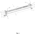
- Fig. 1 illustrates an anode clamp assembly 1 according to the present invention which is intended for attachment to a submerged structure 2 which is to be corrosion protected.
- the anode clamp assembly 1 comprises an elongate bar shaped anode 3 arranged on a rod 4 having rod ends 5 extending from each end 6 of the anode 3 and being closed by an end cover 38. Clamps 7 are attached to the rod ends 5.
- Fig. 1 the anode 3 is a new anode to be attached.
- An existing anode 8 is illustrated.
- the existing anode has a steel bar 9 arranged with protruding end parts at each end of the anode 8, which steel bar 9 is used for the connection to the structure 2.
- the attachment is established through welding.
- the steel bar 9 could be attached by bolting.
- the existing anode 8 is casted around the steel bar 9.
- the anode 3 is provided with eyelets 10 which are intended for handling the anode with suitable tools for transport and attachment.
- Fig. 2-4 more clearly illustrates the structure of the clamp 7.
- each clamp comprises two first legs 11,11'.
- Each of the clamps has an intermediate bore 12 arranged in an intermediate position between the ends of the legs 11,11'.
- the intermediate bore 12 is arranged for rotation around a first rotation axis 13 which is defined by the rod ends 5.
- a locking disc 37 is secured to the rod end 5 in order to maintain the two first legs 11,11' in their position.
- the locking disc 37 could be secured by any suitable means including welding.
- Each of the first legs 11,11' is provided with a gripping jaw 14,14' for attachment to the steel bar 9.
- the gripping jaws 14,14' are arranged at a first end 15 of the first legs.
- At the second end 16 of the first legs second legs 17,17' are connected through a hinge 18,18'.
- Each of the hinges 18,18' has a second rotation axis 19,19'.
- the second legs 17,17' are hinged to each other through a hinge 20 which defines a third rotation axis 21. This construction forms an over-centre acting knee joint.
- the first rotation axis 13 and the third rotation axis 21 are arranged in a common plane which extend in the vertical plane as seen in Fig. 2 and extend in the elongate direction of the anode 3. This common plane would also be a symmetry plane for the clamp 7.
- the first 17 of the second legs are provided with a T-form.
- an extension 22 is provided which constitutes a stop which is arranged in contact with the material 23 surrounding the bores 12.
- the other branch 24 of the beam of T-formed leg extends upwardly and is provided with a hole 25. This hole is intended for cooperation with the tool for activating and deactivating the clamp 7.
- the force to be used for activating or deactivating the clamp 7 is extending in one direction.
- a device for activating and deactivating the clamp could be a hydraulic cylinder (not shown) which is attached to the hole 25 and connected with a Remote Operated Vehicle which is also supporting the anode 3 through a grip in the eyelets 10.
- leg 17 need only to have the L-form and that other construction could be used for activating or deactivating the clamp.
- the first legs 11,11' comprise two leg parts 28,29; 28',29' being arranged under an angle 27 being between 15 and 45°.
- the bore 12 is arranged between the two leg parts.
- the two first leg parts 28,28' are arranged substantially parallel within the cross sections covered by anodes 3,8.
- the second leg parts 29,29' are arranged under a mutual angle 40 and between these two leg parts 29,29' the second legs 17,17' are arranged.
- the first leg 11 is made of two superposed metal plates 30 and it also occurs that the second leg 17' is made of two superposed metal plates 31. Furthermore, it occurs that the first leg 11' is made of one single metal plate 32, and that the second leg 17 is made of one single metal plate 33. Accordingly, the legs could be connected with each other in the manner illustrated in Fig. 4 and thereby have a rather limited extension.
- the anode 3 is of aluminium and the rod is made of steel.
- Fig. 5 illustrates a partial view of a jack-up leg 35 being provided with anodes 8.
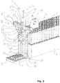
- Figs. 6 and 7 illustrate different types of anodes. It occurs that the anodes are made of aluminium casted around a steel bar 9 or a tube 36.
- the steel bar or tube acts as a support for the anode 8 and it is typically attached to a structure by welding or bolting.
Landscapes
- Engineering & Computer Science (AREA)
- General Engineering & Computer Science (AREA)
- Mechanical Engineering (AREA)
- Chemical & Material Sciences (AREA)
- Materials Engineering (AREA)
- Metallurgy (AREA)
- Organic Chemistry (AREA)
- Civil Engineering (AREA)
- Structural Engineering (AREA)
- Combustion & Propulsion (AREA)
- Ocean & Marine Engineering (AREA)
- Prevention Of Electric Corrosion (AREA)
Claims (9)
- Anodenklemmanordnung (1) zur Befestigung an einer untergetauchten Struktur (2), die korrosionsgeschützt werden soll, und Folgendes umfassend:- eine längliche stabförmige oder zylindrische Anode (3), die auf einer Stange (4) angeordnet ist, die Stangenenden (5) aufweist, die sich aus jedem Ende (6) der Anode (3) erstrecken,- Klemmen (7), die an den Stangenenden (5) befestigt sind, wobei- jede Klemme (7) zwei erste Schenkel (11, 11') umfasst, die eine Zwischenbohrung (12) aufweisen und die zur Drehung um eine erste Rotationsachse (13) angeordnet sind,- jeder aus den ersten Schenkeln (11, 11') an einem ersten Ende (15) mit einer Klemmbacke (14) versehen ist,
dadurch gekennzeichnet, dass- die Klemmbacke (14) zur Befestigung an einem Teil, das mit der Struktur (2) verbunden ist, bestimmt ist, und- jeder der ersten Schenkel (11, 11') an einem zweiten Ende (16) mit einem zweiten Schenkel (17, 17') über erste Scharniere (18, 18'), die eine zweite Rotationsachse (19, 19') aufweisen, gelenkig verbunden ist, und- die zweiten Schenkel (17, 17') miteinander über ein zweites Scharnier (20), das eine dritte Rotationsachse (21) aufweist, gelenkig verbunden sind, um ein Schnappkniegelenk zusammen mit den zwei ersten Schenkeln (11, 11') zu bilden, und- wobei die erste Rotationsachse (13) durch die Stangenenden (5) definiert ist, und- die erste Rotationsachse (13) und die dritte Rotationsachse (21) in einer gemeinsamen Ebene angeordnet sind, die eine Symmetrieebene für die Klemme (7) ist, und wobei ein Anschlag an einem ersten (17) der zweiten Schenkel in Form eines Endabschnitts bereitgestellt ist, der sich über das zweite Scharnier (20) in einer Richtung gegen die erste Rotationsachse (13) erstreckt, um die korrekte Kraft herzustellen, wenn die Klemme (7) durch eine Kraft aktiviert wird, die das Schnappkniegelenk zu den ersten Scharnieren (18, 18') hin drückt. - Anordnung (1) nach Anspruch 1, wobei der erste (17) der zweiten Schenkel L-förmig ist und der Anschlag durch den kurzen Teil des L-förmigen Schenkels bereitgestellt wird.
- Anordnung (1) nach einem der vorstehenden Ansprüche, wobei die Stange (4) ein hohles Rohr ist, das an beiden Enden (5) geschlossen ist.
- Anordnung (1) nach einem der vorstehenden Ansprüche, wobei die ersten Schenkel (11, 11') zwei Schenkelteile (28, 29, 28', 29') umfassen, die in einem Winkel angeordnet sind, der zwischen 15 und 45° liegt, und wobei die Bohrung (12) an der Verbindung zwischen den zwei Schenkelteilen (28, 29, 28', 29') angeordnet ist.
- Anordnung (1) nach einem der vorstehenden Ansprüche, wobei die Anode (3) aus Aluminium ist und die Stange (4) aus Stahl ist.
- Anordnung (1) nach einem der vorstehenden Ansprüche, wobei die ersten und die zweiten Schenkel (11, 11', 17, 17') aus Metallplatten (30, 31) hergestellt sind, vorzugsweise aus Stahl.
- Anordnung (1) nach Anspruch 6, wobei mindestens manche der Schenkel (11, 11', 17, 17') aus übereinanderliegenden Metallplatten (30, 31) hergestellt sind, zwischen denen die anderen Schenkel (11, 11', 17, 17'), die aus einer Metallplatte (30, 31) hergestellt sind, angeordnet sind.
- Anordnung (1) nach einem der vorstehenden Ansprüche, wobei die Klemme (7) im verriegelten Zustand eine elektrische und konstruktive Verbindung an den Backen (14, 14') und an den Bohrungen (12) in den ersten Schenkeln (11, 11') herstellt.
- Verwendung einer Anordnung (1) nach einem der vorstehenden Ansprüche, dadurch gekennzeichnet, dass die Klemmbacken (14, 14') mit einer Stange (4) verbunden sind, die als Stütze für eine Anode (3) fungiert und die Stangenenden (5) aufweist, die sich von jedem Ende der Anode (8) erstrecken und als Stütze für die Anode (3) fungieren und an der Struktur (2) befestigt sind.
Applications Claiming Priority (2)
| Application Number | Priority Date | Filing Date | Title |
|---|---|---|---|
| DKPA201570348A DK178690B1 (en) | 2015-06-04 | 2015-06-04 | Anode clamp assembly and use of such assembly |
| PCT/DK2016/050161 WO2016192736A1 (en) | 2015-06-04 | 2016-06-03 | Anode clamp assembly and use of such assembly |
Publications (3)
| Publication Number | Publication Date |
|---|---|
| EP3303656A1 EP3303656A1 (de) | 2018-04-11 |
| EP3303656A4 EP3303656A4 (de) | 2019-03-06 |
| EP3303656B1 true EP3303656B1 (de) | 2021-01-27 |
Family
ID=57244142
Family Applications (1)
| Application Number | Title | Priority Date | Filing Date |
|---|---|---|---|
| EP16802615.1A Not-in-force EP3303656B1 (de) | 2015-06-04 | 2016-06-03 | Anodenklemmanordnung und verwendung solch einer anordnung |
Country Status (4)
| Country | Link |
|---|---|
| US (1) | US20180171486A1 (de) |
| EP (1) | EP3303656B1 (de) |
| DK (1) | DK178690B1 (de) |
| WO (1) | WO2016192736A1 (de) |
Families Citing this family (2)
| Publication number | Priority date | Publication date | Assignee | Title |
|---|---|---|---|---|
| CN110683018B (zh) * | 2019-10-16 | 2021-10-15 | 南通中远海运川崎船舶工程有限公司 | 一种用于船体的壁付风管结构及其焊接工艺 |
| GB2635889A (en) * | 2023-09-15 | 2025-06-04 | Em&I Maritime Ltd | Method and associated apparatus |
Family Cites Families (11)
| Publication number | Priority date | Publication date | Assignee | Title |
|---|---|---|---|---|
| DE1115204B (de) * | 1959-06-24 | 1961-10-19 | Dowty Rotol Ltd | Friktionsrolle fuer Einrichtungen zum Zusammen- und Auseinanderschrauben von Tiefbohrgestaengerohren |
| US4705331A (en) * | 1985-01-11 | 1987-11-10 | Wayne Graham & Associates International, Inc. | Subsea clamping apparatus |
| FR2676723B1 (fr) * | 1991-05-22 | 1993-09-24 | Topal | Pince de levage a appui reglable automatiquement. |
| FI112536B (fi) * | 2001-01-04 | 2003-12-15 | Outokumpu Oy | Menetelmä ja laitteisto metalliarkkinippujen syöttämiseksi sulatusuuniin |
| CN202072399U (zh) * | 2011-05-18 | 2011-12-14 | 新郑市东升炭素有限公司 | 一种石墨电极夹具 |
| GB2500656B (en) * | 2012-03-28 | 2018-09-12 | Pulse Structural Monitoring Ltd | ROV deployable clamp |
| CN202785277U (zh) * | 2012-07-15 | 2013-03-13 | 鞍钢股份有限公司 | 一种钢包精炼炉电极事故夹具 |
| CN203159715U (zh) * | 2013-03-25 | 2013-08-28 | 深圳市德润青华水下工程科技股份有限公司 | 一种海管牺牲阳极保护装置 |
| ES2535986B1 (es) * | 2013-10-18 | 2016-02-24 | Empresa Municipal De Aguas Y Saneamiento De Murcia, S.A. | Dispositivo para elevación de bombas sumergibles |
| CN203998627U (zh) * | 2014-06-18 | 2014-12-10 | 中国有色(沈阳)冶金机械有限公司 | 一种圆柱形石墨电极夹具 |
| CN204224097U (zh) * | 2014-09-25 | 2015-03-25 | 巨力索具股份有限公司 | 捞电极吊具 |
-
2015
- 2015-06-04 DK DKPA201570348A patent/DK178690B1/en active
-
2016
- 2016-06-03 WO PCT/DK2016/050161 patent/WO2016192736A1/en not_active Ceased
- 2016-06-03 EP EP16802615.1A patent/EP3303656B1/de not_active Not-in-force
- 2016-06-03 US US15/579,242 patent/US20180171486A1/en not_active Abandoned
Non-Patent Citations (1)
| Title |
|---|
| None * |
Also Published As
| Publication number | Publication date |
|---|---|
| EP3303656A4 (de) | 2019-03-06 |
| WO2016192736A1 (en) | 2016-12-08 |
| DK178690B1 (en) | 2016-11-14 |
| DK201570348A1 (en) | 2016-11-14 |
| US20180171486A1 (en) | 2018-06-21 |
| EP3303656A1 (de) | 2018-04-11 |
Similar Documents
| Publication | Publication Date | Title |
|---|---|---|
| US4705331A (en) | Subsea clamping apparatus | |
| EP2159446B1 (de) | Mechanisch lösbarer Schäkelstift | |
| JP5349300B2 (ja) | 重作業用の材料処理剪断機 | |
| EP3303656B1 (de) | Anodenklemmanordnung und verwendung solch einer anordnung | |
| US10378171B2 (en) | Method and apparatus for improved installation of caissons | |
| EP3483342B1 (de) | Vorrichtung und verfahren zur anordnung einer sekundärkonstruktion auf einer offshore-primärkonstruktion | |
| EP3292264B1 (de) | Alternative verriegelungsanordnungen für röhrenverbindungen | |
| KR20120130363A (ko) | 선체블록의 해상운송용 고박 방법 및 장치 | |
| US11148257B2 (en) | Clamping tool | |
| US20100206210A1 (en) | Apparatus for fixing floating bodies | |
| US5902463A (en) | Submersible anode and method | |
| US20220372722A9 (en) | A device for securing a connection to be formed between a leg of a marine structure and a pile of a fundament fastened in a seabed | |
| CN107697231B (zh) | 适用于无杆锚的万能锚架 | |
| WO2017007334A1 (en) | Cathodic protection systems | |
| US8708216B2 (en) | Remote-controlled joining system | |
| KR20240023053A (ko) | 해저 계류 체인을 부식으로부터 보호하기 위한 장치, 시스템 및 방법 | |
| AU2010100343A4 (en) | Scaffolding Support | |
| EP3510181B1 (de) | Gusseiserne anode zur maritimen nutzung | |
| US20150352617A1 (en) | Apparatuses and methods for pressing | |
| DE102009053036A1 (de) | Neodym-Haftmagnet-Befestigungshilfen | |
| WO1987006959A1 (en) | Concrete ballast block with imbedded or attached anodes for cathodic protection of the bolts and their fittings | |
| CN105799885A (zh) | 一种悬挂式变角夹具 | |
| JP3199818U (ja) | 電気防食陽極用吊り具 | |
| NO855211L (no) | Holder for feste av stillasdeler. |
Legal Events
| Date | Code | Title | Description |
|---|---|---|---|
| STAA | Information on the status of an ep patent application or granted ep patent |
Free format text: STATUS: THE INTERNATIONAL PUBLICATION HAS BEEN MADE |
|
| PUAI | Public reference made under article 153(3) epc to a published international application that has entered the european phase |
Free format text: ORIGINAL CODE: 0009012 |
|
| STAA | Information on the status of an ep patent application or granted ep patent |
Free format text: STATUS: REQUEST FOR EXAMINATION WAS MADE |
|
| 17P | Request for examination filed |
Effective date: 20180103 |
|
| AK | Designated contracting states |
Kind code of ref document: A1 Designated state(s): AL AT BE BG CH CY CZ DE DK EE ES FI FR GB GR HR HU IE IS IT LI LT LU LV MC MK MT NL NO PL PT RO RS SE SI SK SM TR |
|
| AX | Request for extension of the european patent |
Extension state: BA ME |
|
| DAV | Request for validation of the european patent (deleted) | ||
| DAX | Request for extension of the european patent (deleted) | ||
| A4 | Supplementary search report drawn up and despatched |
Effective date: 20190204 |
|
| RIC1 | Information provided on ipc code assigned before grant |
Ipc: B66C 1/62 20060101ALI20190129BHEP Ipc: E02B 17/00 20060101ALI20190129BHEP Ipc: C23F 13/20 20060101ALI20190129BHEP Ipc: F16M 13/02 20060101ALI20190129BHEP Ipc: F16L 58/00 20060101ALI20190129BHEP Ipc: C23F 13/18 20060101AFI20190129BHEP Ipc: B66C 1/42 20060101ALI20190129BHEP Ipc: B63B 17/00 20060101ALI20190129BHEP Ipc: F16B 2/18 20060101ALI20190129BHEP Ipc: F16B 2/10 20060101ALI20190129BHEP |
|
| RIC1 | Information provided on ipc code assigned before grant |
Ipc: F16B 2/18 20060101ALI20200727BHEP Ipc: F16L 58/00 20060101ALI20200727BHEP Ipc: B63B 17/00 20060101ALI20200727BHEP Ipc: B66C 1/42 20060101ALI20200727BHEP Ipc: C23F 13/20 20060101ALI20200727BHEP Ipc: F16M 13/02 20060101ALI20200727BHEP Ipc: E02B 17/00 20060101ALI20200727BHEP Ipc: C23F 13/18 20060101AFI20200727BHEP Ipc: F16B 2/10 20060101ALI20200727BHEP Ipc: B66C 1/62 20060101ALI20200727BHEP |
|
| GRAP | Despatch of communication of intention to grant a patent |
Free format text: ORIGINAL CODE: EPIDOSNIGR1 |
|
| STAA | Information on the status of an ep patent application or granted ep patent |
Free format text: STATUS: GRANT OF PATENT IS INTENDED |
|
| INTG | Intention to grant announced |
Effective date: 20200909 |
|
| GRAS | Grant fee paid |
Free format text: ORIGINAL CODE: EPIDOSNIGR3 |
|
| GRAA | (expected) grant |
Free format text: ORIGINAL CODE: 0009210 |
|
| STAA | Information on the status of an ep patent application or granted ep patent |
Free format text: STATUS: THE PATENT HAS BEEN GRANTED |
|
| AK | Designated contracting states |
Kind code of ref document: B1 Designated state(s): AL AT BE BG CH CY CZ DE DK EE ES FI FR GB GR HR HU IE IS IT LI LT LU LV MC MK MT NL NO PL PT RO RS SE SI SK SM TR |
|
| REG | Reference to a national code |
Ref country code: GB Ref legal event code: FG4D |
|
| REG | Reference to a national code |
Ref country code: CH Ref legal event code: EP |
|
| REG | Reference to a national code |
Ref country code: AT Ref legal event code: REF Ref document number: 1358419 Country of ref document: AT Kind code of ref document: T Effective date: 20210215 |
|
| REG | Reference to a national code |
Ref country code: IE Ref legal event code: FG4D |
|
| REG | Reference to a national code |
Ref country code: DE Ref legal event code: R096 Ref document number: 602016052138 Country of ref document: DE |
|
| REG | Reference to a national code |
Ref country code: NL Ref legal event code: MP Effective date: 20210127 |
|
| REG | Reference to a national code |
Ref country code: LT Ref legal event code: MG9D |
|
| REG | Reference to a national code |
Ref country code: AT Ref legal event code: MK05 Ref document number: 1358419 Country of ref document: AT Kind code of ref document: T Effective date: 20210127 |
|
| PG25 | Lapsed in a contracting state [announced via postgrant information from national office to epo] |
Ref country code: GR Free format text: LAPSE BECAUSE OF FAILURE TO SUBMIT A TRANSLATION OF THE DESCRIPTION OR TO PAY THE FEE WITHIN THE PRESCRIBED TIME-LIMIT Effective date: 20210428 Ref country code: FI Free format text: LAPSE BECAUSE OF FAILURE TO SUBMIT A TRANSLATION OF THE DESCRIPTION OR TO PAY THE FEE WITHIN THE PRESCRIBED TIME-LIMIT Effective date: 20210127 Ref country code: HR Free format text: LAPSE BECAUSE OF FAILURE TO SUBMIT A TRANSLATION OF THE DESCRIPTION OR TO PAY THE FEE WITHIN THE PRESCRIBED TIME-LIMIT Effective date: 20210127 Ref country code: NO Free format text: LAPSE BECAUSE OF FAILURE TO SUBMIT A TRANSLATION OF THE DESCRIPTION OR TO PAY THE FEE WITHIN THE PRESCRIBED TIME-LIMIT Effective date: 20210427 Ref country code: PT Free format text: LAPSE BECAUSE OF FAILURE TO SUBMIT A TRANSLATION OF THE DESCRIPTION OR TO PAY THE FEE WITHIN THE PRESCRIBED TIME-LIMIT Effective date: 20210527 Ref country code: LT Free format text: LAPSE BECAUSE OF FAILURE TO SUBMIT A TRANSLATION OF THE DESCRIPTION OR TO PAY THE FEE WITHIN THE PRESCRIBED TIME-LIMIT Effective date: 20210127 Ref country code: BG Free format text: LAPSE BECAUSE OF FAILURE TO SUBMIT A TRANSLATION OF THE DESCRIPTION OR TO PAY THE FEE WITHIN THE PRESCRIBED TIME-LIMIT Effective date: 20210427 |
|
| PG25 | Lapsed in a contracting state [announced via postgrant information from national office to epo] |
Ref country code: SE Free format text: LAPSE BECAUSE OF FAILURE TO SUBMIT A TRANSLATION OF THE DESCRIPTION OR TO PAY THE FEE WITHIN THE PRESCRIBED TIME-LIMIT Effective date: 20210127 Ref country code: AT Free format text: LAPSE BECAUSE OF FAILURE TO SUBMIT A TRANSLATION OF THE DESCRIPTION OR TO PAY THE FEE WITHIN THE PRESCRIBED TIME-LIMIT Effective date: 20210127 Ref country code: PL Free format text: LAPSE BECAUSE OF FAILURE TO SUBMIT A TRANSLATION OF THE DESCRIPTION OR TO PAY THE FEE WITHIN THE PRESCRIBED TIME-LIMIT Effective date: 20210127 Ref country code: RS Free format text: LAPSE BECAUSE OF FAILURE TO SUBMIT A TRANSLATION OF THE DESCRIPTION OR TO PAY THE FEE WITHIN THE PRESCRIBED TIME-LIMIT Effective date: 20210127 Ref country code: LV Free format text: LAPSE BECAUSE OF FAILURE TO SUBMIT A TRANSLATION OF THE DESCRIPTION OR TO PAY THE FEE WITHIN THE PRESCRIBED TIME-LIMIT Effective date: 20210127 |
|
| PG25 | Lapsed in a contracting state [announced via postgrant information from national office to epo] |
Ref country code: IS Free format text: LAPSE BECAUSE OF FAILURE TO SUBMIT A TRANSLATION OF THE DESCRIPTION OR TO PAY THE FEE WITHIN THE PRESCRIBED TIME-LIMIT Effective date: 20210527 |
|
| REG | Reference to a national code |
Ref country code: DE Ref legal event code: R097 Ref document number: 602016052138 Country of ref document: DE |
|
| PG25 | Lapsed in a contracting state [announced via postgrant information from national office to epo] |
Ref country code: EE Free format text: LAPSE BECAUSE OF FAILURE TO SUBMIT A TRANSLATION OF THE DESCRIPTION OR TO PAY THE FEE WITHIN THE PRESCRIBED TIME-LIMIT Effective date: 20210127 Ref country code: CZ Free format text: LAPSE BECAUSE OF FAILURE TO SUBMIT A TRANSLATION OF THE DESCRIPTION OR TO PAY THE FEE WITHIN THE PRESCRIBED TIME-LIMIT Effective date: 20210127 Ref country code: SM Free format text: LAPSE BECAUSE OF FAILURE TO SUBMIT A TRANSLATION OF THE DESCRIPTION OR TO PAY THE FEE WITHIN THE PRESCRIBED TIME-LIMIT Effective date: 20210127 |
|
| PG25 | Lapsed in a contracting state [announced via postgrant information from national office to epo] |
Ref country code: SK Free format text: LAPSE BECAUSE OF FAILURE TO SUBMIT A TRANSLATION OF THE DESCRIPTION OR TO PAY THE FEE WITHIN THE PRESCRIBED TIME-LIMIT Effective date: 20210127 Ref country code: RO Free format text: LAPSE BECAUSE OF FAILURE TO SUBMIT A TRANSLATION OF THE DESCRIPTION OR TO PAY THE FEE WITHIN THE PRESCRIBED TIME-LIMIT Effective date: 20210127 Ref country code: DK Free format text: LAPSE BECAUSE OF FAILURE TO SUBMIT A TRANSLATION OF THE DESCRIPTION OR TO PAY THE FEE WITHIN THE PRESCRIBED TIME-LIMIT Effective date: 20210127 |
|
| PLBE | No opposition filed within time limit |
Free format text: ORIGINAL CODE: 0009261 |
|
| STAA | Information on the status of an ep patent application or granted ep patent |
Free format text: STATUS: NO OPPOSITION FILED WITHIN TIME LIMIT |
|
| REG | Reference to a national code |
Ref country code: DE Ref legal event code: R119 Ref document number: 602016052138 Country of ref document: DE |
|
| 26N | No opposition filed |
Effective date: 20211028 |
|
| PG25 | Lapsed in a contracting state [announced via postgrant information from national office to epo] |
Ref country code: ES Free format text: LAPSE BECAUSE OF FAILURE TO SUBMIT A TRANSLATION OF THE DESCRIPTION OR TO PAY THE FEE WITHIN THE PRESCRIBED TIME-LIMIT Effective date: 20210127 Ref country code: AL Free format text: LAPSE BECAUSE OF FAILURE TO SUBMIT A TRANSLATION OF THE DESCRIPTION OR TO PAY THE FEE WITHIN THE PRESCRIBED TIME-LIMIT Effective date: 20210127 Ref country code: MC Free format text: LAPSE BECAUSE OF FAILURE TO SUBMIT A TRANSLATION OF THE DESCRIPTION OR TO PAY THE FEE WITHIN THE PRESCRIBED TIME-LIMIT Effective date: 20210127 |
|
| REG | Reference to a national code |
Ref country code: CH Ref legal event code: PL |
|
| GBPC | Gb: european patent ceased through non-payment of renewal fee |
Effective date: 20210603 |
|
| PG25 | Lapsed in a contracting state [announced via postgrant information from national office to epo] |
Ref country code: SI Free format text: LAPSE BECAUSE OF FAILURE TO SUBMIT A TRANSLATION OF THE DESCRIPTION OR TO PAY THE FEE WITHIN THE PRESCRIBED TIME-LIMIT Effective date: 20210127 |
|
| REG | Reference to a national code |
Ref country code: BE Ref legal event code: MM Effective date: 20210630 |
|
| PG25 | Lapsed in a contracting state [announced via postgrant information from national office to epo] |
Ref country code: LU Free format text: LAPSE BECAUSE OF NON-PAYMENT OF DUE FEES Effective date: 20210603 |
|
| PG25 | Lapsed in a contracting state [announced via postgrant information from national office to epo] |
Ref country code: LI Free format text: LAPSE BECAUSE OF NON-PAYMENT OF DUE FEES Effective date: 20210630 Ref country code: IT Free format text: LAPSE BECAUSE OF FAILURE TO SUBMIT A TRANSLATION OF THE DESCRIPTION OR TO PAY THE FEE WITHIN THE PRESCRIBED TIME-LIMIT Effective date: 20210127 Ref country code: IE Free format text: LAPSE BECAUSE OF NON-PAYMENT OF DUE FEES Effective date: 20210603 Ref country code: GB Free format text: LAPSE BECAUSE OF NON-PAYMENT OF DUE FEES Effective date: 20210603 Ref country code: DE Free format text: LAPSE BECAUSE OF NON-PAYMENT OF DUE FEES Effective date: 20220101 Ref country code: CH Free format text: LAPSE BECAUSE OF NON-PAYMENT OF DUE FEES Effective date: 20210630 |
|
| PG25 | Lapsed in a contracting state [announced via postgrant information from national office to epo] |
Ref country code: IS Free format text: LAPSE BECAUSE OF FAILURE TO SUBMIT A TRANSLATION OF THE DESCRIPTION OR TO PAY THE FEE WITHIN THE PRESCRIBED TIME-LIMIT Effective date: 20210527 Ref country code: FR Free format text: LAPSE BECAUSE OF NON-PAYMENT OF DUE FEES Effective date: 20210630 |
|
| PG25 | Lapsed in a contracting state [announced via postgrant information from national office to epo] |
Ref country code: BE Free format text: LAPSE BECAUSE OF NON-PAYMENT OF DUE FEES Effective date: 20210630 |
|
| PG25 | Lapsed in a contracting state [announced via postgrant information from national office to epo] |
Ref country code: HU Free format text: LAPSE BECAUSE OF FAILURE TO SUBMIT A TRANSLATION OF THE DESCRIPTION OR TO PAY THE FEE WITHIN THE PRESCRIBED TIME-LIMIT; INVALID AB INITIO Effective date: 20160603 |
|
| PG25 | Lapsed in a contracting state [announced via postgrant information from national office to epo] |
Ref country code: NL Free format text: LAPSE BECAUSE OF NON-PAYMENT OF DUE FEES Effective date: 20210127 Ref country code: CY Free format text: LAPSE BECAUSE OF FAILURE TO SUBMIT A TRANSLATION OF THE DESCRIPTION OR TO PAY THE FEE WITHIN THE PRESCRIBED TIME-LIMIT Effective date: 20210127 |
|
| PG25 | Lapsed in a contracting state [announced via postgrant information from national office to epo] |
Ref country code: MK Free format text: LAPSE BECAUSE OF FAILURE TO SUBMIT A TRANSLATION OF THE DESCRIPTION OR TO PAY THE FEE WITHIN THE PRESCRIBED TIME-LIMIT Effective date: 20210127 |
|
| PG25 | Lapsed in a contracting state [announced via postgrant information from national office to epo] |
Ref country code: TR Free format text: LAPSE BECAUSE OF FAILURE TO SUBMIT A TRANSLATION OF THE DESCRIPTION OR TO PAY THE FEE WITHIN THE PRESCRIBED TIME-LIMIT Effective date: 20210127 |
|
| PG25 | Lapsed in a contracting state [announced via postgrant information from national office to epo] |
Ref country code: MT Free format text: LAPSE BECAUSE OF FAILURE TO SUBMIT A TRANSLATION OF THE DESCRIPTION OR TO PAY THE FEE WITHIN THE PRESCRIBED TIME-LIMIT Effective date: 20210127 |