EP3292264B1 - Alternative verriegelungsanordnungen für röhrenverbindungen - Google Patents
Alternative verriegelungsanordnungen für röhrenverbindungen Download PDFInfo
- Publication number
- EP3292264B1 EP3292264B1 EP16720541.8A EP16720541A EP3292264B1 EP 3292264 B1 EP3292264 B1 EP 3292264B1 EP 16720541 A EP16720541 A EP 16720541A EP 3292264 B1 EP3292264 B1 EP 3292264B1
- Authority
- EP
- European Patent Office
- Prior art keywords
- locking
- clamping
- clamping member
- longitudinal axis
- threaded
- Prior art date
- Legal status (The legal status is an assumption and is not a legal conclusion. Google has not performed a legal analysis and makes no representation as to the accuracy of the status listed.)
- Active
Links
Images


Classifications
-
- E—FIXED CONSTRUCTIONS
- E21—EARTH OR ROCK DRILLING; MINING
- E21B—EARTH OR ROCK DRILLING; OBTAINING OIL, GAS, WATER, SOLUBLE OR MELTABLE MATERIALS OR A SLURRY OF MINERALS FROM WELLS
- E21B19/00—Handling rods, casings, tubes or the like outside the borehole, e.g. in the derrick; Apparatus for feeding the rods or cables
- E21B19/12—Rope clamps ; Rod, casings or tube clamps not secured to elevators
Definitions
- This disclosure relates to alternative locking arrangements for tubular connections.
- the disclosure relates to the use of locking members (preferably threaded) to maintain a clamping force applied by a clamping member associated with an outer tube to an inner tube lying within the outer tube.
- the disclosure also relates to a lightweight tool that can be used in subsea operations in order to apply pressure to a clamping member to clamp two tubes together.
- the method of locking is an important consideration as this is used to ensure the clamping load is both reliable and ideally releasable throughout the lifetime of the connector.
- the methods are suitable for a range of conditions and loads and also suitable for both manual or diver operation and also for operations using Remotely Operated Vehicles or ROVs. Due to the costly nature of subsea operations there is advantage in using an operation that is simple, quick and ideally releasable.
- the ability to release the connection is of particular value as should the subsea structure or equipment require maintenance or replacement then release of the connection would allow recovery of the element and later reinstatement.
- the connectors are permanent feature that are mounted on the surface of the outer tubular and therefore need to be of a suitable profile to minimise the potential for snagging of wires and or controls or life support umbilicals used during installation or maintenance of the structure by both divers and ROVs.
- a tool to operate (engage and disengage) the connection would ideally be able to be positioned, operated and recovered by either diver and or ROV. It will therefore need to be sufficiently powerful to generate the required large clamping loads but ideally have a low submerged weight and have a sympathetic shape to permit easy handling manoeuvrability and operation subsea.
- the present disclosure provides a system for preventing the movement of a clamping member, the system comprising:
- the initial clamping application is delivered via a Thrust Rod and the locking members (e.g. Locking Pins) subsequently carry the clamping load passively.
- the locking members e.g. Locking Pins
- said at least one locking member is moveable towards the clamping member after the clamping member has been moved towards the longitudinal axis of the first member.
- the clamping load may be applied directly via the locking member(s) (e.g. threaded pins). This could be achieved by applying (heavy) torque to the threaded pins and effectively driving the pad towards the inner tubular.
- said at least one locking member is moveable towards the clamping member to effect movement of the clamping member towards the longitudinal axis of the first member.
- the locking member(s) directly act on the pad to force the pad towards an inner tubular.
- 'directly act' does not necessarily mean that there is direct and uninterrupted contact between e.g. the shaft of the locking member and the pad.
- the movement of the locking member directly results in a movement of the clamping member.
- said at least one locking member is a pair of locking members.
- the locking members are coincidental (in line with) with a thrust rod (where present).
- each of said pair of locking members are positioned so that they intersect substantially along the longitudinal axis of the first member.
- the at least one locking member (e.g. single member, or multiple (e.g. two) members) can be orientated orthogonally to the longitudinal axis of the first member and not be radial to it.
- Such an arrangement may also require a profiled tail portion of the at least one locking member (i.e. the portion in contact with the clamping member) in order to maximise contact area with the clamping member or with an inner tube if no clamping member is present.
- the profiled tail portion may be a separate part from the shaft of the locking member, so as to accommodate any rotation of the shaft of the locking member during locking/clamping.
- the clamping member may be modified so that its outer face in contact with the locking member comprises a receiving portion for the locking member (e.g. a cup) which is able to receive the orthogonally orientated locking member and maximise force transmitted to the clamping member.
- the pair of locking members are preferably positioned so that their longitudinal axes intersect substantially along the longitudinal axis of the thrust pin.
- the tail portion of the at least one locking member (i.e. the portion in contact with the clamping member) has a convex/concave profile, wherein said tail portion interacts with a complementary concave/convex profiled part, respectively, of the clamping member in order to accommodate misalignment between the locking member and the clamping member.
- the tail portion may be integral with a shaft of the locking member, or may comprise a separate part on which the shaft of the locking member acts.
- the at least one locking member comprises a plurality of parts.
- the at least one locking member comprises at least a portion that is threaded, said threaded portion corresponding to a complementary threaded portion on at least one locking frame associated with said first member, and/or on said first member.
- a collar affixed to the inner face of the outer (first) member. This acts to provide support at the or each location opposite the said clamping member.
- This is so designed to maintain the circularity of the inner tube so that the inner tube when unclamped may be withdrawn from the outer tube or vice versa with the tubes being caused to jam against each other.
- One or more edges of the collar can be tapered in order to facilitate entry of the second member.
- said clamping member is formed from at least a part of said collar.
- the clamping member when viewed from the side is either round, square or rectangular. It is curved in plan, viewed axially along the length of the collar to match the shape of the inner tube.
- the clamping member is preferably of substantial thickness similar to the thickness of the collar and therefore able to sit within the thickness of the collar thereby allowing uninterrupted passage of the inner tube through the outer tube and collar without contacting the surface of the clamping member.
- the collar or clamping member further comprises an arrangement of spacer plates.
- the clamping member e.g. pad
- the first member outer tubular
- the clamping member can be formed from part of the first member (outer tubular) rather than the collar.
- the situation where there is no separate collar and the pad is set within the outer tubular is mentioned in GB2404092B (see Figs 27 , 28 and claim 11 and related description, incorporated herein by reference).
- the permanently attached portion (such as the locking frame and/or reaction plate) can be arranged in a manner whereby the Collar is integrated with or attached directly to the outer sleeve, thereby avoiding the need for the outer sleeve over the height of the collar.
- This may allow significant material and fabrication cost savings. It is recognized that the effective removal of a relatively large portion of the outer tubular in the form of the pad may adversely affect the strength of the sleeve and as a result (heavy) radial stiffener plates can be added to reinforce the collar portion.
- This embodiment without an outer sleeve (i.e. outer member) over the height of the collar may be used in any of the disclosed embodiments herein.
- the attachment of the collar forming the wall of the outer tubular member may be made by e.g. circumferential welds.
- the collar in this arrangement or in any other embodiment in this disclosure may, or may not, comprise friction increasing means, such as for example grooves, ribs, coating, and/or protrusions, for increasing the holding force of the clamping arrangement.
- friction increasing means may improve the fixing of the first and second members and prevent relative movement between the members.
- the present disclosure provides a system whereby the clamping member is present in the wall of the first member (e.g. outer tubular).
- the locking member(s) can therefore be associated with a framework affixed to the outer member and can act on the clamping member in order to drive its movement towards an inner member or in order to prevent its movement away from an inner member once the clamping member has been moved into a clamping configuration.
- a thrust rod This transmits the force applied from a pressure inducing member, typically a hydraulic piston that is positionable by e.g. a ROV or a diver, to the inner (second) member, optionally via the clamping member.
- a pressure inducing member typically a hydraulic piston that is positionable by e.g. a ROV or a diver
- a thrust rod said thrust rod being accessible from outside of said first member.
- the thrust rod is associated with the clamping member in order to be able to transmit force to the clamping member.
- both the Thrust Rod (where used) and the at least one locking member penetrate the first member (e.g. outer tubular) through prepared holes in the wall of the first member and be in contact directly with the second member (inner tube) without the use of either a collar or a pad. It is recognised that the capacity of such an arrangement would likely be considerably less than pad, and optional collar, arrangement, but there can be an application suitable for lightly loaded connections.
- the present disclosure provides a system for clamping a first member and second member together, said system comprising an inner second member and an outer first member, said inner second member being concentrically aligned within said outer first member, said outer first member having in moveable association with it at least one clamping and/or locking member wherein said at least one clamping and/or locking member is moveable towards the inner second member to contact the inner second member to clamp said first and second members together; wherein said at least one clamping and/or locking member comprises means preventing it from passively moving away from the second member in order to prevent loss of the clamping force on the second member.
- the means is a threaded portion on the clamping and/or locking member.
- said at least one clamping and/or locking member comprises at least two clamping and/or locking members.
- At least two clamping and/or locking members are positioned in substantially the same plane on the first member.
- a tool to deliver a clamping load to a clamping member comprising a pressure inducing member (e.g. hydraulic cylinder) which in use exerts a force transmissible to said clamping member, said tool further comprising equipment used for its function housed within a protective framework or compartment, which protective framework comprises perforated sides in order reduce weight of said tool.
- a pressure inducing member e.g. hydraulic cylinder
- the protective framework of the tool contains buoyant material in order to reduce apparent weight when submersed.
- Thrust rod and thrust rod are considered interchangeable.
- Thrust rods /Pins are shown as solid cylinders but could equally be rectangular or square and equally be of a hollow cross section.
- a substantially (horizontal) radial pair of (optionally threaded) locking pins disposed radially and substantially perpendicular to the longitudinal axes of the concentric inner and outer tubulars so as to intersect along the longitudinal axis of the thrust pin.
- the locking pins can optionally be housed within and/or aligned using tubular sleeves. These members provide a direct means of load transfer between the outer tubular and the reaction plate. This load transfer capacity may be reinforced using stiffener plates.
- the one or more locking pins may be offset to the longitudinal axis of the thrust pin.
- the locking pin(s) are not housed within a tubular sleeve.
- the locking pin(s) may be housed within a tubular sleeve.
- another embodiment discloses an arrangement with a pair of threaded locking pins set substantially perpendicular to the longitudinal axes of the concentric inner and outer tubulars and offset either side of a substantially centrally located thrust pin and/or cylinder release pin.
- the locking pins may optionally be housed within a tubular sleeve.
- Optional longitudinal and/or transverse stiffeners provide reinforcement to the tubular sleeve and a reactive load path between the outer tubular and the reaction plate. The load transfer capacity is substantial and may be reduced as required by removal of either the longitudinal and vertical stiffeners or the tubular sleeves.
- the tool of the present disclosure may be introduced vertically or sideways between the locking pins, depending on the location of the locking pins.
- Another embodiment shows an arrangement with a single threaded locking pin set substantially perpendicular to the longitudinal axes of the concentric inner and outer tubulars and substantially centrally between e.g. two thrust pins and cylinder release pins.
- a further embodiment of the invention shows use of a spring or multiple springs set within the hydraulic cylinder assembly for returning the piston to the original retracted position.
- the connection between the two tubulars is via deformation of the inner tubular is created by exerting a heavy clamping force using a pressurised hydraulic cylinder, or similar, to apply a clamping load to the inner tubular against the collar via a sympathetically shaped pad .
- This will deform the circular section inner tubular into a slightly ovalised shape.
- Such deformation may be limited so that the deformation is largely within the elastic property range of the inner tubular.
- Once deformed this deformation and thereby the clamping reactive force may be maintained using a locking arrangement in the form of threaded locking pins.
- the quantity and orientation of the locking pins may vary to suit construction methods. Arrangements one or more locking pins may be utilised with the pin(s) arranged perpendicular or inclined to the longitudinal axes of the tubulars and may be set radially or orthogonal with respect to the plane of the connected tubulars.
- the locking arrangement utilises at least one threaded Locking Pin to maintain the deformation in the Inner Tubular.
- the threaded Locking Pin is located in a threaded hole set in a Reaction Plate tied to the outer Tubular via a framework.
- One end of the Locking Pin is contactable with the outside of the Pad.
- the other ends of the Locking Pin passes through the Reaction Plate and is accessible from outside of the Reaction Plate allowing external engagement of the Locking Pin and thereby permitting rotation and subsequent axial movement of the threaded Locking Pin relative to both the Reaction Plate and the Pad.
- This axial movement allows any gap between the end of the Locking Pin and the Pad to be either closed or opened following deformation of the Inner Tubular. Following closure of this gap the hydraulic cylinder may be depressurised and removed.
- a threaded block is attached to the Reaction Plate. Again the Locking Pin is accessible at the outer end allowing relative axial movement to close or open the gap between the Locking Pin and the back of the Bearing Pad.
- Locking Pins are aligned radially to the concentric centre of the axes of the connected tubular members , this being an efficient means of maintaining the deformed shape of the inner tubular as it prevents rotation of the pad and subsequent relaxation of the contact forces.
- Locking Pins are at the same elevation as the applied clamping force (Thrust Rod), this being an efficient means of maintaining the deformed shape of the inner tubular as it prevents rotation of the pad and subsequent relaxation of the contact forces once the initial clamping force is removed.
- Locking Pins are fully threaded and encased in a solid threaded section, this this being an efficient means of maintaining the deformed shape of the inner tubular by minimising the relaxing strain in the Locking Pin due to its continual threaded engagement along its full length.
- the exposed ends of the Locking pins may have a suitably shaped (square or hexagonal) opening or projection to allow docking of a removable operator or handle suitable for diver or ROV use.
- a graduated marker or scale may be fixed to the Reaction Pad to allow visual reference to the amount of axial movement of each Locking Pin.
- a heavy load distribution pad may be introduced at the back of the Bearing Pad used to improve dispersion of the loads and reduce localised plastic deformation of both pad and pile. This reduces the losses in the system when load is transferred to the Locking Pin.
- the Collar Hole has a close fitting Pad that permits forward and reverse travel only for the Pad in a direction perpendicular to the axis of the Inner Tubular.
- a close fitting Pad that permits forward and reverse travel only for the Pad in a direction perpendicular to the axis of the Inner Tubular.
- an arrangement of Spacer Plates may be used. These Spacer Plates may be fixed to either the external edge of the Pad or the internal edge of the Collar Hole.
- a Tool to deliver the clamping load to the Thrust Rod which will optionally include an Hydraulic Cylinder. This may bare against a threaded Hydraulic Cylinder Release Pin set within and projecting from the Reaction Pad. On depressurisation of the Cylinder the Release Pin may be rotated to reduce the projection and thereby create a gap that may allow the Tool and attached Hydraulic Cylinder to be easily withdrawn.
- the Tool may optionally include hydraulic tubing and equipment housed within a protective framework or compartment.
- the hydraulic tubing and equipment may be suspended from the top or side plate and may be preassembled with full access prior to being attached to the remainder of the protective compartment. This allows ready removal and maintenance of the hydraulic components.
- the Hydraulic cylinder may be suspended in a protective shroud at the bottom of the Tool.
- the protective compartment is able to contain buoyant material in rigid preformed units in a shape sympathetic to the shape of the compartment or in loose form.
- the loose form material may be in the form of minispheres or microspheres or cubes or other pre-formed geometric shape that are compatible to allow efficient packing within the compartment and between the hydraulic components and tubing.
- the Protective compartment may have perforated sides in order to allow free drainage of the compartment and also allow cleaning of the buoyant material.
- valve stem or other fragile components within the valve may be protected from over torqueing and damage by permitting only rotation in the opening direction. This will protect the valve stem from damage.
- the single direction rotation will be ensured by slipping a circular teethed ratchet plate over the valve handle and setting a pawl to prevent inadvertent rotation in the closing direction.
- the external shape of the Tool Compartment shall assist entry or docking of the Tool into the Tool Receptacle within the Connector Frame.
- the sloping interface between the piston and Thrust pin is either a sloping machined face or a cap plate that can be fixed to the piston or Thrust pin to create a sloping interface.
- the sloping interface arranged to allow a gap to develop the instance the RRU is lifted.
- the radial pair of aligned locking pins set at the same elevation as the Thrust Pin. This is aligned with the Thrust Pin to minimise losses on depressurisation. This is because there is no appreciable rotation of the pile on depressurisation.
- a sleeve or sleeves to protect the locking pin and provide a maintainable annulus to contain preservative fluid or grease to prevent or minimise corrosion.
- the hydraulic cylinder shall incorporate at least one spring contained within a cowling to force the piston into the retracted position when the hydraulic fluid pressure is removed.
- An embodiment of the present disclosure shows a horizontal radial pair of threaded locking pins disposed radially and substantially perpendicular to the longitudinal axes of the concentric inner and outer tubulars so as to intersect along the longitudinal axis of the thrust pin.
- Fig 1 shows a second member (an inner tubular (2)) concentrically placed within a first member (the outer tubular (1)).
- a collar (3) (optional) is attached to the outer tubular (1) to centralise the inner tubular with respect to the outer tubular.
- a connector frame (20) is mounted on the outer tubular (1).
- This figure shows the tool (30) positioned above the connector frame receptacle (16) prior to lowering and docking into the connector frame.
- the tool consists of a hydraulic cylinder (32) (pressure inducing member) suspended from a robust tool frame (33) in which is housed the hydraulic system (44) that receives intermediate pressure hydraulic fluid from the ROV via the hotstab (43).
- the hydraulic system (44) receives the input hydraulic fluid from the ROV at intermediate pressure and via use of a pressure intensifier generates a high pressure output that it supplies to the hydraulic cylinder (32).
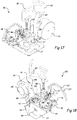
- Fig 2 shows the outer cylinder (1) with a section cut away revealing the attached collar (3) (where present).
- the collar (3) has a pad hole (14) into which is set a close fitting clamping member (pad (15)).
- a connector frame (20) consisting of a vertical reaction plate (4) fixed to the outer tubular (1) optionally via one or more (e.g. a pair of) lower vertical stiffener(s) (9) and one or more (e.g. a pair of) upper vertical stiffener(s) (10) and also optionally via a locking frame (e.g. a locking pin block (5)).
- a pair of locking members (threaded locking pins (8)) run through the locking pin block (5).
- the locking member (pin) is also shown in the fully withdrawn position (8').
- the locking pins are aligned radially to the axis of the concentric tubular and collar arrangement (1, 2 and 3). Once the tool is docked into position the hydraulic cylinder (32) sits between and aligns with the centre of the thrust rod (17) and the threaded cylinder release pin (11).
- This threadable pin or pins is/are not a locking member but effectively an adjustable surface of the Reaction Plate against which the pressure inducing member pushes. This provides not only a means to accommodate variable lengths of hydraulic cylinder but is also useful (following removal of the hydraulic fluid pressure) to reduce or relieve the residual load that could otherwise be locked in to the system and assists in allowing recovery of the hydraulic cylinder. This is particularly useful when the spring return feature is not used.
- the piston (pressure inducing member) in the hydraulic cylinder pushes the thrust rod forward and reacts against the cylinder release pin.
- the thrust rod is attached to the pad (15) via a recessed bolt (18) and the two are held in position with respect to the outer tubular (1) by the thrust rod retaining pin (130) that runs through a hole (21) passing through the thrust rod.
- Activation of the hydraulic cylinder (32) drives the thrust rod and pad (15) forward against the inner tubular (2).
- the thrust rod retaining pin (130) Prior to pressurising and activating the hydraulic cylinder the thrust rod retaining pin (130) is removed by withdrawal (130 ') or alternatively the relatively low resistance of the thrust rod retaining pin will be overcome by shear through during activation.
- Both the locking pins (8) and the cylinder release pin (11) may be operated or rotated by any suitable means.
- a removable square (or hexagonal or similar) section drive grab handle (7) The drive section is stabbed into the complementary (e.g. square (or hexagonal or similar)) socket at the end of either the locking pins and/or cylinder release pins and rotated either clockwise or ant-clockwise to move the respective element inward or outward with respect to the assembly thereby locking or releasing the element.
- the handle (7) once used may be recovered leaving the profile of the assembly snag free in profile.
- the locking pins or cylinder release pins may have permanently fixed operator handles to eliminate the need to stab the drive sections into the sockets thereby reduce operation time.
- Fig 5 shows a similar view to Fig 2 but the outer tubular (1) that is fixed to the collar (3) for convenience has not been shown.
- This view exposes the collar (3), the collar hole (14) and the pad (15).
- Fig 6 shows a horizontal cross sectional view through the centre of the axis of the thrust rod (17).
- Figs 3 and 4 shows the tool docked into the connector frame receptacle (16) with the underside(31) of the tool (30) resting on the upper surface (13) of the reaction plate (4).
- the tool preferably is constructed using a rigid outer frame (33). This frame protects the hydraulic equipment and tubing and also provides an ROV interface plate (35) onto which is mounted the controls. It is appreciated that the interface plate may equally be orientated in the horizontal or the vertical for convenience.
- the controls include a range of valve operators (38 and 39), a gauge for monitoring of the delivered cylinder pressure (42) and both the hotstab receptacle (43) and the dummy hotstab receptacle (37).
- the ROV or diver removes the hotstab dummy (47) and places it into the dummy hotstab receptacle (37). Then the hotstab (not shown) is placed into the receptacle (43) and the supply line activated.
- a ratchet (40) and pawl (41) is used that allows only one way operation.
- the framework (33) To reduce tool weight further and increase manoeuvrability of the tool subsea mesh (45) is fixed to the framework (33).
- This mesh is shown on Fig 3 and 4 on the front face of the tool but may also be used on one or more (e.g. two, three, four, all) other sides of the tool.
- This provides an effective container or box for buoyancy material.
- the buoyancy material may be in the form of rigid blocks of syntactic foam or similar but for convenience buoyancy material may be supplied in small shaped units. Some examples of these buoyant shapes are indicated (46) but may be in any suitable shape allowing the buoyancy box to be filled in loose form buoyancy shapes.
- the ideal shape of the buoyancy units would suit the manufacturing process and also allow the irregular space in the box to be filled in a convenient and efficient way.
- the various shapes will result in a different packing density and the ideal shape and size will be determined by experiment and analysis.
- the grill (45) not only contains the buoyancy units but also allows free flooding of the tool. This free passage of water through the mesh removes the potential for damaging the box by external hydrostatic pressure and also allows free draining of the box once recovered from the sea.
- Fig 5 shows a similar view to Fig 2 but with the outer tubular (1) removed revealing the complete collar (3) and a fuller view of the pad (15).
- Fig 6 shows a horizontal cross section through the plane of the locking pins (8) and thrust pin (17), pad (15) and the hydraulic cylinder release pin (11).
- the view shows the initial position prior to docking of the tool (30) and engagement of the connector.
- the thrust rod retaining pin (130) is, at this stage, set within the hole (21) passing through the thrust rod.
- the inner tubular (2) is concentric within the collar (3) and pad (15).
- the inside face (23) of the threaded cylinder release pin (11) is set slightly forward of the inside face of the reaction plate (4) and the hydraulic cylinder is yet to be positioned within the connector frame receptacle (16).
- Fig 7 shows similar views to Fig 6 but with the hydraulic cylinder (32) set within the connector frame receptacle (16) and the back of the hydraulic cylinder body (24) in contact with the inside face (23) of the threaded cylinder release pin.
- the piston (25) is in the retracted position within the hydraulic cylinder body (24).
- the front face of the locking pins (8) are in positive contact with the outside face of the pad (15).
- These contact faces (26) may be concave/convex to accommodate misalignment due to orientation and inclination of the pad (15) with respect to the inner tubular (2).
- Fig 8 shows similar views to Fig 7 but with the hydraulic cylinder (32) pressurised and the piston (25) moved forward against the thrust rod (17) that in turn forces the pad (15) against the inner tubular (2).
- the annular gap (27) is closed along the axis of the piston (25) and there is high pressure contact between the inside face of the pad (15) and the outside face of the inner tubular (2) and also the inside face of the collar(3) and the outside face of the inner tubular. This high pressure will deform the inner tubular (2) into a slightly non circular form and to a lesser extent deform the rest of the assembly. Whilst the piston pressure is maintained the threaded locking pins (8) are rotated to once again be in positive contact at the interfaces (26).
- the hydraulic fluid pressure in the compartment (28) may then be released and the relative deformations will be largely maintained via the locking pins (8).
- the tool (30) may be withdrawn.
- the threaded hydraulic release pin (11) may be rotated to open up a gap between the back of the hydraulic cylinder and the inside face (23) of the hydraulic release pin.
- an arrangement similar to the first with a radial pair of threaded locking pins disposed radially and substantially perpendicular to the longitudinal axes of the concentric inner and outer tubulars so as to intersect along the longitudinal axis of the thrust pin.
- the locking pins are aligned using tubular sleeves. These members provide a direct means of load transfer between the outer tubular and the reaction plate. This load transfer capacity may be reinforced using stiffener plates.
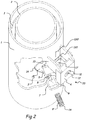
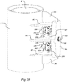
- Figs 9 shows the modified connector frame mounted on the outer tubular (1).
- the tool (30) is not shown but may be similar to the first embodiment.
- Fig 10 shows a cross section through the plane of the locking pins (51) and thrust pin (17).
- the arrangement shows a wider reaction plate (55) spanning between tubular sleeves (50) so as to provide direct load transfer from reaction plate (55) to outer tubular (1).
- the tubular sleeves (50) also provide protection to the locking pins (51) and may be reinforced by the top and bottom stiffener plates (48 and 49) respectively.
- the void (57) between the locking pin (51) and the tubular sleeves may be filled with preservative or lubricant to maintain function and minimise corrosion of the locking pin (51).
- a section of the locking pin (52) is threaded to engage with a corresponding thread on the inside face of the hole through the reaction plate.
- the locking pin may be cut and a concave/convex bearing face (60) introduced to allow the locking pin to articulate. It will be appreciated that this feature can be present in any of the arrangements described herein.
- the handles (54) will provide means to rotate and advance /retract the locking pin.
- the threaded section (52) of the locking pin may have a socket hole (53) to receive the end of handle (54).
- the handle for the locking pin and the hydraulic cylinder release pin (11) may be common to allow interchangability of the handles with either the locking pin and hydraulic cylinder release sockets (53 and 12) respectively.
- a graduated scale may be fixed to allow the relative movement of the locking pin with respect to the reaction plate to be monitored and recorded. This feature can be present in any of the arrangements described herein, irrespective of the specific arrangement of the locking members themselves.
- the locking pin to pad (15) contact faces (56) may also be concave/convex to allow small amount of rotation to accommodate misalignment of the locking pin.
- An alternative arrangement may utilise a threaded connection along the full length of the locking pin and tubular sleeve(50).
- Fig 10 shows a half shell receptacle (59) suitable for support of the hydraulic cylinder. Such a feature can be present in any of the arrangements described herein.
- An inclined thrust rod retaining pin (29) is shown running through the thrust rod (17). Such an arrangement can be present in any of the arrangements described herein.
- the thrust rod retaining pin (29) Prior to activating the hydraulic cylinder the thrust rod retaining pin (29) is removed by withdrawal or alternatively the relatively low resistance of the thrust rod retaining pin will be overcome by shear through during activation.
- a single threaded locking pin disposed substantially perpendicular to the longitudinal axes of the concentric inner and outer tubulars and offset to the longitudinal axis of the thrust pin.
- the locking pin need not, but can be, housed within a tubular sleeve.
- Stiffeners provide a reactive load path between the outer tubular and the reaction plate. This load transfer capacity may be reinforced using a tubular sleeve similar to the second embodiment.
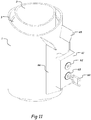
- Figs 11 shows the single locking pin (63) offset from the hydraulic cylinder release pin (62) and the stiffeners (66) attaching the reaction plate (61) to the outer tubular (1).
- the tool (30) is not shown but may be similar to that already described.
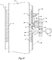
- Fig 12 shows a cross section through the plane of the locking pin (67) and thrust pin (17) along the longitudinal axes of the outer tubular (1) and inner tubular (2).
- the hydraulic cylinder (32) only is shown between the thrust rod (17) and hydraulic cylinder release pin (62) whereas the remainder of the tool (30) is not shown.
- the hydraulic cylinder body (24) and associated piston (25) is aligned axially with thrust rod (17) and the hydraulic cylinder release pin (62).
- the locking pin (67) has a threaded section (63) that engages with the threaded hole in the reaction plate (61).
- the contact face of the piston (25) and the thrust rod (17) is inclined at a small angle (108) to assist with the removal of the hydraulic cylinder body (24) following depressurisation.
- Such an arrangement may also be present in any of the arrangements described herein.
- the locking pins are housed within a tubular sleeve.
- they do not need to be housed within a tubular sleeve. Instead, they can be located within e.g. a threaded block.
- Longitudinal and transverse stiffeners provide reinforcement to the tubular sleeve and a reactive load path between the outer tubular and the reaction plate.
- the load transfer capacity, as shown, is substantial and may be reduced as required by removal of either the longitudinal and vertical stiffeners or the tubular sleeves.
- the tool may be introduced sideways between the locking pins.
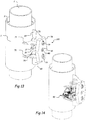
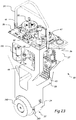
- Fig 13 shows the two threaded locking pins (79) offset longitudinally with respect to the thrust rod (17) and the hydraulic release pin (80).
- the tool (90) may be introduced laterally into the tool receptacle (16).
- the reaction plate (78) is the key element of connector frame (100) which is mounted on the outer tubular (1) via two tubular sleeves (76) plus lower and upper transverse stiffeners (70 and 71) and lower and upper longitudinal stiffeners (68 and 69).
- a pin hole (81) in the reaction plate (78) is available to receive a tee bar (74) used to locate the tool (90) within the tool receptacle (16).
- Such a feature may be present in any of the arrangements described herein.
- Fig 14 the tool (90) is shown located in the tool receptacle (16) such that the hydraulic cylinder (32) sits between the inside face of the hydraulic release pin (80) and the bearing face of the thrust pin (17).
- the underside of the tool (90) is arranged to rest on the top of the lower transverse stiffener (70) such that the hydraulic cylinder (32) is indexed and aligned with the thrust rod (17) and hydraulic cylinder pin (80).
- Guide plate (75) are also used to assist with insertion and correct alignment of the tool (90).
- Such guide plates may also be present in any of the arrangements described herein.
- Fig 15 the outer tubular (1) and the collar (3) is shown part removed to show the pad (15).
- Spacer plates (72) are affixed (e.g. welded) to the side edges of the pad (15) at intervals around the circumference. These will be fitted to suit the gap between the collar hole (14 as shown in Fig. 2 ) and the pad (15) to ensure a positive contact but allow sufficient clearance to allow free transverse movement of the pad (15) within the collar hole (14). It is important to note that although free movement of the pad towards the longitudinal axis of the inner tubular (2) is essential, it is preferable that the pad does not significantly move either longitudinally or transverse with respect to the hole (14) as this may cause rotation of the pad and incorrect bearing between pad and inner tubular.
- Fig. 15 shows a verticle arrangements of locking members, it will be clear that the spacer plates can be present on the clamping member of any of the arrangements described herein. Alternatively, the spacer plates where present may be affixed to the collar.
- Fig 16 shows a longitudinal cross section of the embodiment through the locking pins, the thrust rod and the hydraulic cylinder release pin (80).
- This view also shows the upper and lower locking tubular sleeves (76 and 77).
- the ends of the tubular sleeves are affixed (e.g. welded) to the reaction plate (78) and the outer tubular (1).
- the weld preparation is shown in this view, following welding the tubular sleeves will have full contact joint with the adjoining elements.
- Figs 17 and 18 show the tool (90).
- the tool is constructed using a rigid outer frame (33).
- This frame protects the hydraulic equipment and tubing (44) and also provides an ROV interface plate (35) onto which is mounted the controls.
- the controls include a range of valve operator (38), a gauge (42) for monitoring of the delivered cylinder pressure and both the hotstab (86) and the dummy hotstab receptacle (37).
- To pressurise the cylinder the ROV or diver delivers pressurised hydraulic fluid via the supply hose (87) and hotstab (86) into the hotstab receptacle (126).
- the hydraulic fluid return hose (127) is also shown.
- the fluid pressure may be increased using an intensifier within the hydraulic assembly and delivers the pressure to the hydraulic cylinder (32) (pressure inducing member) in a cavity between the cylinder body (24) and piston (25), driving the piston forward and causing the clamping action on the inner tubular (2). Following engagement of the locking pins the fluid supply of pressurised fluid is terminated.
- the hydraulic system (44) may then be depressurised by opening valve (38) allowing fluid pressure to dissipate and allowing fluid to return via the hotstab and the return hose(127). Then the diver or ROV may remove the hotstab (86) by grabbing handle (82) and withdrawing hotstab from the hotstab receptacle (126).
- the dummy (47) is then recovered from the dummy hotstab receptacle (37) and placed into the hotstab receptacle (126) to prevent entry of seawater and detritus into the hydraulic system (44).
- a ratchet (40) and pawl (41) is used that allows only one way operation - to open.
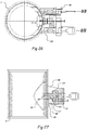
- the reaction plate (96) has a single threaded hole with a single threaded locking pin (99) aligned perpendicular to the axis of the concentrically arranged internal tubular (2) and the outer tubular (1).
- the end of the locking pin a has a shaped projection in the form of a hexagonal or square bar over which a tool may be placed to assist rotation of the locking pin. This rotation will advance or retract the locking pin towards or away from an internal pad.
- the reaction plate is fixed to the outer tubular (1) via a framework consisting of horizontal plates (92, 93) and vertical stiffeners (94,95).
- a tubular sleeve (97) may be used to house the locking pin(99) providing guidance and also providing a means to contain preservatives to maintain serviceability of the locking pin and associated threaded surfaces.
- the pad (15) is held in position via the bolt (18) attached to the locking pin (99).
- Two hydraulic cylinders (104) are shown between the reaction plate (96) and the outer tubular (1).
- the hydraulic cylinders have integral thrust rods (102) that are attached to the hydraulic cylinders.
- the thrust rods pass through openings (128) in the outer sleeve (1) allowing direct bearing onto the back of the pad (15).
- Fig 20 shows a longitudinal section through the connection.
- the hydraulic cylinders are located on plates (129) to align the piston (106) with the outer sleeve hole (128).
- Pressurised hydraulic fluid may be introduced via inlet port (106) to move the piston (102) forward to push the pad (15) against the inner tubular (2) and thereby introduce clamping and deformation load of the inner tubular (2) against the collar (3).
- the introduction of equal pressure in the two hydraulic cylinders simultaneously, via an hydraulic hose (not shown) advances the pad against the inner tubular with equal load.
- Application of the required clamping load will advance the pad and shear the bolt (105) allowing subsequent free rotation of locking pin (99).
- Figs 21 and 22 shows a CRA locking pin 112 with a threaded section (113) that engages with the internal thread (115) of a CRA shouldered boss (114).
- the reduced section of the collared boss (116) provides a bearing shoulder (117).
- This shoulder (117) bears against a similar face (120) formed by the stepped opening (118,119) machined within the reaction plate (110) with the collar larger diameter (114) fitting closely within the larger diameter opening (119) of the stepped hole and the smaller diameter (116) sitting within the smaller diameter opening (118) of the stepped hole.
- a spring or multiple springs set within a pressure inducing member (e.g. the hydraulic cylinder assembly) for returning the piston to the original retracted position.
- Fig 23 shows the tool (30) from the reverse position. This view repeats details shown in e.g. Figs 1 , 3 and 4 but without the connector (20) mounted on the outer tubular (1).
- the view shows the pressure intensifier (131).
- the hydraulic cylinder (32) also shows a spring cowling (140) fixed to the cylinder body (24) e.g. using bolts (143).
- Fig 24 shows a cross section through the middle of the hydraulic cylinder assembly (32) in the pressurised state with the void (28) between the piston a (25) and the cylinder body (24) filled with fluid under pressure so that the piston face (147) is forward of the spring cowling face (142). Under this condition the spring 150 or springs (150 and 151) are in a compressed condition.
- the piston (25) has a piston extension piece (146) mounted on the front of the piston(152) using one or more bolts (149).
- the bolt head (148) is sunk into a recess (145) set into the face of the piston extension piece (146). It may be that the front face (147) is sloping to allow easy separation from the thrust rod (17 on Fig 12 ).
- this extension piece (146) may be integral with the piston (25).
- the compressed springs (150 and 151) will have sufficient stored energy to return to the former shape (150' and 151') and the piston gap (28) will reduce to zero (28').
- Figs 26 and 27 show an arrangement of the invention similar to that described and shown in Fig 9 and Fig 10 but the locking members (pins) are arranged to move in a direction that is orthogonal to the longitudinal axis of the first member rather than radial.
Landscapes
- Engineering & Computer Science (AREA)
- Geology (AREA)
- Mining & Mineral Resources (AREA)
- Life Sciences & Earth Sciences (AREA)
- General Life Sciences & Earth Sciences (AREA)
- Fluid Mechanics (AREA)
- Mechanical Engineering (AREA)
- Environmental & Geological Engineering (AREA)
- Physics & Mathematics (AREA)
- Geochemistry & Mineralogy (AREA)
- Earth Drilling (AREA)
- Quick-Acting Or Multi-Walled Pipe Joints (AREA)
- Lining Or Joining Of Plastics Or The Like (AREA)
- Mutual Connection Of Rods And Tubes (AREA)
- Clamps And Clips (AREA)
Claims (15)
- Ein System zum Verhindern der Bewegung eines Klemmelements (15), wobei das System Folgendes beinhaltet:ein erstes Element (1), an dem ein Verbinderrahmen befestigt ist, wobei der Verbinderrahmen (20) eine Reaktionsplatte (4) und mindestens einen Verriegelungsrahmen (5) beinhaltet;wobei das erste Element ein Klemmelement (15) beinhaltet, wobei das erste Element eine Längsachse aufweist und wobei das Klemmelement zu der Achse hin und von dieser weg bewegbar ist;wobei der Verbinderrahmen so angeordnet ist, dass er ein Werkzeug (30) mit einem druckinduzierenden Mittel (32), das zwischen der Reaktionsplatte und dem Klemmelement positionierbar ist entfernbar aufnehmen kann;mindestens ein Verriegelungselement, das jedes über den mindestens einen Verriegelungsrahmen an dem ersten Element gehalten wird und jedes mit dem Klemmelement in Kontakt gebracht werden kann;dadurch gekennzeichnet, dassder Verriegelungsrahmen so angeordnet ist, dass jedes von dem mindestens einen Verriegelungselement (8) hinsichtlich des druckinduzierenden Mittels des Werkzeugs versetzt ist, wenn sich das Werkzeug zwischen der Reaktionsplatte und dem Klemmelement in Position befindet;wobei jedes von dem mindestens einen Verriegelungselement zu dem Klemmelement hin bewegbar ist, um zu verhindern, dass sich das Klemmelement von der Längsachse weg in seine Ausgangsposition bewegt.
- System gemäß Anspruch 1, wobei das mindestens eine Verriegelungselement (8) zu dem Klemmelement hin bewegbar ist, nachdem das Klemmelement zu der Längsachse des ersten Elements hin bewegt worden ist.
- System gemäß einem der vorhergehenden Ansprüche, wobei das mindestens eine Verriegelungselement (8) ein Paar Verriegelungselemente ist;
optional, wobei das Paar Verriegelungselemente in der gleichen oder im Wesentlichen der gleichen Ebene senkrecht zu der Längsachse des ersten Elements positioniert ist oder wobei das Paar Verriegelungselemente in der gleichen oder im Wesentlichen der gleichen Ebene parallel zu der Längsachse entlang des ersten Elements positioniert ist; und optional,
wobei das Paar Verriegelungselemente so positioniert ist, dass sich ihre Längsachsen im Wesentlichen entlang der Längsachse des ersten Elements schneiden. - System gemäß einem der Ansprüche 1-2, wobei das mindestens eine Verriegelungselement (8) orthogonal zu der Längsachse des ersten Elements ausgerichtet ist.
- System gemäß einem der vorhergehenden Ansprüche, wobei das mindestens eine Verriegelungselement (8):(a) einen Endabschnitt, der mit dem Klemmelement in Kontakt gebracht werden kann, und einen Kopfabschnitt, der von außerhalb des ersten Elements zugänglich ist, beinhaltet, wobei vorzugsweise der Endabschnitt des mindestens einen Verriegelungselements ein konvexes/konkaves Profil aufweist, wobei der Endabschnitt mit einem jeweils komplementären konkaven/konvexen Profilteil des Klemmelements zusammenwirkt, um eine Fehlausrichtung zwischen dem Verriegelungselement und dem Klemmelement auszugleichen; und/oder(b) eine Vielzahl von Teilen beinhaltet, wobei die Vielzahl von Teilen optional einstückig sind oder sich in beweglicher Zuordnung zueinander befinden, um zu ermöglichen, dass das Verriegelungselement gelenkig ist; und/oder(c) mindestens einen Abschnitt beinhaltet, der mit einem Gewinde versehen ist, wobei der Gewindeabschnitt einem komplementären Gewindeabschnitt an dem mindestens einen Verriegelungsrahmen und/oder an dem ersten Element entspricht, wobei optional mindestens der Gewindeabschnitt des Verriegelungselements aus einem korrosionsbeständigen Material hergestellt ist und/oder wobei optional der Verriegelungsrahmen einen entfernbaren Gewindezapfen beinhaltet, wobei der Zapfen vorzugsweise aus einem korrosionsbeständigen Material hergestellt ist.
- System gemäß einem der vorhergehenden Ansprüche, wobei der mindestens eine Verriegelungsrahmen (5) mindestens eine Hülse beinhaltet, wobei jede der mindestens einen Hülse mindestens einen wesentlichen Teil der Länge jedes von dem mindestens einen Verriegelungselement umgibt.
- System gemäß einem der vorhergehenden Ansprüche, wobei das mindestens eine Verriegelungselement (8) entlang seiner Länge im Wesentlichen vollständig mit Gewinde versehen ist, wobei optional der mindestens eine Verriegelungsrahmen einen Gewindeabschnitt beinhaltet, der sich mindestens über den größten Teil der Länge, vorzugsweise die gesamte Länge des Verriegelungselements erstreckt, wenn das Verriegelungselement vor der Bewegung des Klemmelements zu der Längsachse des ersten Elements hin in dem Rahmen positioniert ist.
- System gemäß einem der vorhergehenden Ansprüche, wobei sich neben einem Kopfabschnitt des mindestens einen Verriegelungselements (8) eine abgestufte Markierung oder Skala befindet, um einen visuellen Bezug auf die Menge an axialer Bewegung des Verriegelungselements zu ermöglichen, und/oder eine Bezugslinie oder -markierung an einem Verriegelungselement und einem Verriegelungsrahmen, um ein Bestimmen der Menge an Drehung des Verriegelungselements und dadurch der Menge an axialer Bewegung zu ermöglichen.
- System gemäß einem der vorhergehenden Ansprüche, wobei das erste Element (1) ferner einen Kragen beinhaltet,
und wobei sich das Klemmelement durch den Kragen erstreckt, wobei optional das Klemmelement aus mindestens einem Teil des Kragens gebildet ist und/oder wobei optional der Kragen oder das Klemmelement ferner eine Anordnung von Abstandshalterplatten beinhaltet, um jegliche bedeutende Bewegung des Klemmelements anders als in einer Richtung senkrecht zu der Längsachse des ersten Elements zu verhindern. - System gemäß einem der vorhergehenden Ansprüche, wobei das System ferner ein zweites Element beinhaltet, wobei das zweite Element (2) innerhalb des ersten Elements platziert ist und wobei das Klemmelement eine Kraft auf das zweite Element ausübt, wenn das Klemmelement zu der Längsachse des ersten Elements hin bewegt wird.
- System gemäß einem der vorhergehenden Ansprüche, wobei das Klemmelement (15) mit mindestens einer Schubstange verbunden ist, wobei jedes von dem mindestens einen Verriegelungselement hinsichtlich der Längsachse der mindestens einen Schubstange versetzt ist,
und optional:(i) wobei die mindestens eine Schubstange eine Schubstange ist und wobei das System ein Paar Verriegelungselemente beinhaltet, wobei die Verriegelungselemente so positioniert sind, dass sich ihre Längsachsen im Wesentlichen entlang der Längsachse der Schubstange schneiden; oder(ii) wobei die mindestens eine Schubstange zwei Schubstangen ist und wobei das System zwei Schubstangen und ein Verriegelungselement beinhaltet. - System gemäß Anspruch 11, wobei die Schubstange (17) oder eine an der Schubstange angebrachte Kappenplatte eine geneigte Fläche beinhaltet, die mit einer komplementären geneigten Fläche an einem druckinduzierenden Element eine Schnittstelle bildet.
- System gemäß einem der vorhergehenden Ansprüche, wobei der Verbinderrahmen (20) ferner eine einstellbare Oberfläche der Reaktionsplatte beinhaltet.
- System gemäß einem der vorhergehenden Ansprüche, wobei der Verbinderrahmen ferner eine oder mehrere Führungsplatten (75) beinhaltet, um das Positionieren eines druckinduzierenden Elements zu erleichtern.
- System gemäß einem der vorhergehenden Ansprüche, wobei das System ein zweites Element (2) beinhaltet, das in dem ersten Element platziert ist, und jedes von dem mindestens einen Verriegelungselement ein Mittel beinhaltet, das verhindert, dass sich das mindestens eine Verriegelungselement passiv von dem zweiten Element weg bewegt, um einen Verlust der Klemmkraft auf das zweite Element zu verhindern.
Applications Claiming Priority (2)
| Application Number | Priority Date | Filing Date | Title |
|---|---|---|---|
| GBGB1507389.3A GB201507389D0 (en) | 2015-04-30 | 2015-04-30 | Alternative locking methods for tubular connections |
| PCT/GB2016/051255 WO2016174473A1 (en) | 2015-04-30 | 2016-04-29 | Alternative locking arrangements for tubular connections |
Publications (2)
| Publication Number | Publication Date |
|---|---|
| EP3292264A1 EP3292264A1 (de) | 2018-03-14 |
| EP3292264B1 true EP3292264B1 (de) | 2019-06-12 |
Family
ID=53488924
Family Applications (1)
| Application Number | Title | Priority Date | Filing Date |
|---|---|---|---|
| EP16720541.8A Active EP3292264B1 (de) | 2015-04-30 | 2016-04-29 | Alternative verriegelungsanordnungen für röhrenverbindungen |
Country Status (8)
| Country | Link |
|---|---|
| US (1) | US10465454B2 (de) |
| EP (1) | EP3292264B1 (de) |
| AU (1) | AU2016254798B2 (de) |
| BR (1) | BR112017023330B1 (de) |
| CA (1) | CA2983180C (de) |
| GB (1) | GB201507389D0 (de) |
| MX (1) | MX376707B (de) |
| WO (1) | WO2016174473A1 (de) |
Families Citing this family (5)
| Publication number | Priority date | Publication date | Assignee | Title |
|---|---|---|---|---|
| US9644443B1 (en) | 2015-12-07 | 2017-05-09 | Fhe Usa Llc | Remotely-operated wellhead pressure control apparatus |
| US12252949B2 (en) | 2018-03-28 | 2025-03-18 | Fhe Usa Llc | Fluid connection assembly with adapter release |
| US20190301260A1 (en) | 2018-03-28 | 2019-10-03 | Fhe Usa Llc | Remotely operated fluid connection |
| CN111828725B (zh) * | 2020-06-17 | 2025-03-14 | 合肥热电集团有限公司 | 一种阀门阀杆用锁闭卡 |
| US20250270891A1 (en) * | 2024-02-27 | 2025-08-28 | Saudi Arabian Oil Company | Closed compartment well tool for wellhead re-packing |
Family Cites Families (14)
| Publication number | Priority date | Publication date | Assignee | Title |
|---|---|---|---|---|
| GB404092A (en) | 1932-09-23 | 1934-01-11 | Wilfred Leslie Goodfellow | Improvements in manoeuvre signalling devices for use on motor vehicles |
| US4406485A (en) * | 1981-04-27 | 1983-09-27 | Arrowhead Continental | Tubular connector |
| US4497592A (en) | 1981-12-01 | 1985-02-05 | Armco Inc. | Self-levelling underwater structure |
| GB2185847B (en) | 1986-01-28 | 1990-01-04 | English Electric Valve Co Ltd | Laser apparatus |
| US5035542A (en) * | 1988-01-25 | 1991-07-30 | Max Bassett | Apparatus and method for releasable connections |
| US5071175A (en) * | 1990-06-14 | 1991-12-10 | Kennedy Jr Harold | Pipe restrainer |
| GB2332256B (en) * | 1997-12-05 | 2002-01-16 | Britannia Engineering Consulta | Tubular connection |
| TW510955B (en) * | 2001-02-20 | 2002-11-21 | Waterworks Technology Dev Org | Supporting device for non-averaged force |
| US7578932B2 (en) * | 2004-11-05 | 2009-08-25 | Christopher Ralph Cantolino | Condensate recovery and treatment system |
| US7478483B2 (en) * | 2005-05-05 | 2009-01-20 | Shell Oil Company | Adjustable support apparatus and method |
| US7861982B1 (en) * | 2006-11-16 | 2011-01-04 | International Clamps, Inc. | Subsea clamp for hoses and control lines |
| GB0716786D0 (en) | 2007-08-31 | 2007-10-10 | Britannia Engineering Consulta | Interfitting tubular members |
| GB0903520D0 (en) | 2009-03-03 | 2009-04-08 | Britannia Engineering Consulta | Improvements in and relating to clamping of interfitting tubular members |
| GB2496647A (en) * | 2011-11-17 | 2013-05-22 | Britannia Engineering Consultancy Ltd | Clamping device for subsea tubular member |
-
2015
- 2015-04-30 GB GBGB1507389.3A patent/GB201507389D0/en not_active Ceased
-
2016
- 2016-04-29 CA CA2983180A patent/CA2983180C/en active Active
- 2016-04-29 MX MX2017013363A patent/MX376707B/es active IP Right Grant
- 2016-04-29 EP EP16720541.8A patent/EP3292264B1/de active Active
- 2016-04-29 US US15/570,302 patent/US10465454B2/en active Active
- 2016-04-29 BR BR112017023330-4A patent/BR112017023330B1/pt not_active IP Right Cessation
- 2016-04-29 AU AU2016254798A patent/AU2016254798B2/en not_active Ceased
- 2016-04-29 WO PCT/GB2016/051255 patent/WO2016174473A1/en not_active Ceased
Non-Patent Citations (1)
| Title |
|---|
| None * |
Also Published As
| Publication number | Publication date |
|---|---|
| MX2017013363A (es) | 2018-03-07 |
| US20180128063A1 (en) | 2018-05-10 |
| CA2983180C (en) | 2023-11-07 |
| EP3292264A1 (de) | 2018-03-14 |
| GB201507389D0 (en) | 2015-06-17 |
| CA2983180A1 (en) | 2016-11-03 |
| WO2016174473A1 (en) | 2016-11-03 |
| AU2016254798A1 (en) | 2017-11-09 |
| MX376707B (es) | 2025-03-07 |
| BR112017023330A2 (pt) | 2018-08-14 |
| US10465454B2 (en) | 2019-11-05 |
| AU2016254798B2 (en) | 2021-04-22 |
| BR112017023330B1 (pt) | 2022-07-26 |
Similar Documents
| Publication | Publication Date | Title |
|---|---|---|
| EP3292264B1 (de) | Alternative verriegelungsanordnungen für röhrenverbindungen | |
| US10012040B2 (en) | Methods of using oilfield lift caps and combination tools | |
| EP2159446B1 (de) | Mechanisch lösbarer Schäkelstift | |
| US8882066B2 (en) | Buoyant clamp for tubular members | |
| US4523878A (en) | Remotely replaceable guidepost method and apparatus | |
| CA2754012C (en) | Improvements in and relating to clamping arrangements | |
| US20040040702A1 (en) | Temporary abandonment cap | |
| NO20140415A1 (no) | Koplingsanordning for å forbinde to borerørseksjoner og en fremgangsmåte for bruk av samme | |
| US7431535B2 (en) | Clamp for anchoring production tube, electrohydraulic hose and electric cable simultaneously | |
| NO345388B1 (no) | Nødfrigjøringsverktøy for en undervanns klemkonnektor og tilhørende fremgangsmåte | |
| GB2575276A (en) | Cantilevered resilient strut connector | |
| EP3172471B1 (de) | Mehrere ausfallmodusklemmen und zugehörige verfahren | |
| EP2185847B1 (de) | Zusammenfügen von röhrenförmigen gliedern | |
| EP2447463B1 (de) | Unterwassermaschine und Verfahren zum Verdübeln von rohrförmigen Teilen | |
| WO2013072688A2 (en) | Improved clamping device | |
| NO20141062A1 (no) | Verktøy for fjerning av et momentmellomstykke |
Legal Events
| Date | Code | Title | Description |
|---|---|---|---|
| STAA | Information on the status of an ep patent application or granted ep patent |
Free format text: STATUS: THE INTERNATIONAL PUBLICATION HAS BEEN MADE |
|
| PUAI | Public reference made under article 153(3) epc to a published international application that has entered the european phase |
Free format text: ORIGINAL CODE: 0009012 |
|
| STAA | Information on the status of an ep patent application or granted ep patent |
Free format text: STATUS: REQUEST FOR EXAMINATION WAS MADE |
|
| 17P | Request for examination filed |
Effective date: 20171123 |
|
| AK | Designated contracting states |
Kind code of ref document: A1 Designated state(s): AL AT BE BG CH CY CZ DE DK EE ES FI FR GB GR HR HU IE IS IT LI LT LU LV MC MK MT NL NO PL PT RO RS SE SI SK SM TR |
|
| AX | Request for extension of the european patent |
Extension state: BA ME |
|
| DAV | Request for validation of the european patent (deleted) | ||
| DAX | Request for extension of the european patent (deleted) | ||
| GRAP | Despatch of communication of intention to grant a patent |
Free format text: ORIGINAL CODE: EPIDOSNIGR1 |
|
| STAA | Information on the status of an ep patent application or granted ep patent |
Free format text: STATUS: GRANT OF PATENT IS INTENDED |
|
| INTG | Intention to grant announced |
Effective date: 20190108 |
|
| GRAS | Grant fee paid |
Free format text: ORIGINAL CODE: EPIDOSNIGR3 |
|
| GRAA | (expected) grant |
Free format text: ORIGINAL CODE: 0009210 |
|
| STAA | Information on the status of an ep patent application or granted ep patent |
Free format text: STATUS: THE PATENT HAS BEEN GRANTED |
|
| AK | Designated contracting states |
Kind code of ref document: B1 Designated state(s): AL AT BE BG CH CY CZ DE DK EE ES FI FR GB GR HR HU IE IS IT LI LT LU LV MC MK MT NL NO PL PT RO RS SE SI SK SM TR |
|
| REG | Reference to a national code |
Ref country code: GB Ref legal event code: FG4D |
|
| REG | Reference to a national code |
Ref country code: CH Ref legal event code: EP |
|
| REG | Reference to a national code |
Ref country code: AT Ref legal event code: REF Ref document number: 1142757 Country of ref document: AT Kind code of ref document: T Effective date: 20190615 |
|
| REG | Reference to a national code |
Ref country code: DE Ref legal event code: R096 Ref document number: 602016015204 Country of ref document: DE |
|
| REG | Reference to a national code |
Ref country code: IE Ref legal event code: FG4D |
|
| REG | Reference to a national code |
Ref country code: NL Ref legal event code: FP |
|
| REG | Reference to a national code |
Ref country code: LT Ref legal event code: MG4D |
|
| PG25 | Lapsed in a contracting state [announced via postgrant information from national office to epo] |
Ref country code: HR Free format text: LAPSE BECAUSE OF FAILURE TO SUBMIT A TRANSLATION OF THE DESCRIPTION OR TO PAY THE FEE WITHIN THE PRESCRIBED TIME-LIMIT Effective date: 20190612 Ref country code: LT Free format text: LAPSE BECAUSE OF FAILURE TO SUBMIT A TRANSLATION OF THE DESCRIPTION OR TO PAY THE FEE WITHIN THE PRESCRIBED TIME-LIMIT Effective date: 20190612 Ref country code: FI Free format text: LAPSE BECAUSE OF FAILURE TO SUBMIT A TRANSLATION OF THE DESCRIPTION OR TO PAY THE FEE WITHIN THE PRESCRIBED TIME-LIMIT Effective date: 20190612 Ref country code: AL Free format text: LAPSE BECAUSE OF FAILURE TO SUBMIT A TRANSLATION OF THE DESCRIPTION OR TO PAY THE FEE WITHIN THE PRESCRIBED TIME-LIMIT Effective date: 20190612 Ref country code: SE Free format text: LAPSE BECAUSE OF FAILURE TO SUBMIT A TRANSLATION OF THE DESCRIPTION OR TO PAY THE FEE WITHIN THE PRESCRIBED TIME-LIMIT Effective date: 20190612 |
|
| REG | Reference to a national code |
Ref country code: NO Ref legal event code: T2 Effective date: 20190612 |
|
| PG25 | Lapsed in a contracting state [announced via postgrant information from national office to epo] |
Ref country code: BG Free format text: LAPSE BECAUSE OF FAILURE TO SUBMIT A TRANSLATION OF THE DESCRIPTION OR TO PAY THE FEE WITHIN THE PRESCRIBED TIME-LIMIT Effective date: 20190912 Ref country code: GR Free format text: LAPSE BECAUSE OF FAILURE TO SUBMIT A TRANSLATION OF THE DESCRIPTION OR TO PAY THE FEE WITHIN THE PRESCRIBED TIME-LIMIT Effective date: 20190913 Ref country code: RS Free format text: LAPSE BECAUSE OF FAILURE TO SUBMIT A TRANSLATION OF THE DESCRIPTION OR TO PAY THE FEE WITHIN THE PRESCRIBED TIME-LIMIT Effective date: 20190612 Ref country code: LV Free format text: LAPSE BECAUSE OF FAILURE TO SUBMIT A TRANSLATION OF THE DESCRIPTION OR TO PAY THE FEE WITHIN THE PRESCRIBED TIME-LIMIT Effective date: 20190612 |
|
| REG | Reference to a national code |
Ref country code: AT Ref legal event code: MK05 Ref document number: 1142757 Country of ref document: AT Kind code of ref document: T Effective date: 20190612 |
|
| PG25 | Lapsed in a contracting state [announced via postgrant information from national office to epo] |
Ref country code: EE Free format text: LAPSE BECAUSE OF FAILURE TO SUBMIT A TRANSLATION OF THE DESCRIPTION OR TO PAY THE FEE WITHIN THE PRESCRIBED TIME-LIMIT Effective date: 20190612 Ref country code: AT Free format text: LAPSE BECAUSE OF FAILURE TO SUBMIT A TRANSLATION OF THE DESCRIPTION OR TO PAY THE FEE WITHIN THE PRESCRIBED TIME-LIMIT Effective date: 20190612 Ref country code: SK Free format text: LAPSE BECAUSE OF FAILURE TO SUBMIT A TRANSLATION OF THE DESCRIPTION OR TO PAY THE FEE WITHIN THE PRESCRIBED TIME-LIMIT Effective date: 20190612 Ref country code: PT Free format text: LAPSE BECAUSE OF FAILURE TO SUBMIT A TRANSLATION OF THE DESCRIPTION OR TO PAY THE FEE WITHIN THE PRESCRIBED TIME-LIMIT Effective date: 20191014 Ref country code: RO Free format text: LAPSE BECAUSE OF FAILURE TO SUBMIT A TRANSLATION OF THE DESCRIPTION OR TO PAY THE FEE WITHIN THE PRESCRIBED TIME-LIMIT Effective date: 20190612 Ref country code: CZ Free format text: LAPSE BECAUSE OF FAILURE TO SUBMIT A TRANSLATION OF THE DESCRIPTION OR TO PAY THE FEE WITHIN THE PRESCRIBED TIME-LIMIT Effective date: 20190612 |
|
| PG25 | Lapsed in a contracting state [announced via postgrant information from national office to epo] |
Ref country code: IS Free format text: LAPSE BECAUSE OF FAILURE TO SUBMIT A TRANSLATION OF THE DESCRIPTION OR TO PAY THE FEE WITHIN THE PRESCRIBED TIME-LIMIT Effective date: 20191012 Ref country code: SM Free format text: LAPSE BECAUSE OF FAILURE TO SUBMIT A TRANSLATION OF THE DESCRIPTION OR TO PAY THE FEE WITHIN THE PRESCRIBED TIME-LIMIT Effective date: 20190612 Ref country code: IT Free format text: LAPSE BECAUSE OF FAILURE TO SUBMIT A TRANSLATION OF THE DESCRIPTION OR TO PAY THE FEE WITHIN THE PRESCRIBED TIME-LIMIT Effective date: 20190612 Ref country code: ES Free format text: LAPSE BECAUSE OF FAILURE TO SUBMIT A TRANSLATION OF THE DESCRIPTION OR TO PAY THE FEE WITHIN THE PRESCRIBED TIME-LIMIT Effective date: 20190612 |
|
| REG | Reference to a national code |
Ref country code: DE Ref legal event code: R097 Ref document number: 602016015204 Country of ref document: DE |
|
| PG25 | Lapsed in a contracting state [announced via postgrant information from national office to epo] |
Ref country code: TR Free format text: LAPSE BECAUSE OF FAILURE TO SUBMIT A TRANSLATION OF THE DESCRIPTION OR TO PAY THE FEE WITHIN THE PRESCRIBED TIME-LIMIT Effective date: 20190612 |
|
| PLBE | No opposition filed within time limit |
Free format text: ORIGINAL CODE: 0009261 |
|
| STAA | Information on the status of an ep patent application or granted ep patent |
Free format text: STATUS: NO OPPOSITION FILED WITHIN TIME LIMIT |
|
| PG25 | Lapsed in a contracting state [announced via postgrant information from national office to epo] |
Ref country code: DK Free format text: LAPSE BECAUSE OF FAILURE TO SUBMIT A TRANSLATION OF THE DESCRIPTION OR TO PAY THE FEE WITHIN THE PRESCRIBED TIME-LIMIT Effective date: 20190612 Ref country code: PL Free format text: LAPSE BECAUSE OF FAILURE TO SUBMIT A TRANSLATION OF THE DESCRIPTION OR TO PAY THE FEE WITHIN THE PRESCRIBED TIME-LIMIT Effective date: 20190612 |
|
| 26N | No opposition filed |
Effective date: 20200313 |
|
| PG25 | Lapsed in a contracting state [announced via postgrant information from national office to epo] |
Ref country code: IS Free format text: LAPSE BECAUSE OF FAILURE TO SUBMIT A TRANSLATION OF THE DESCRIPTION OR TO PAY THE FEE WITHIN THE PRESCRIBED TIME-LIMIT Effective date: 20200224 Ref country code: SI Free format text: LAPSE BECAUSE OF FAILURE TO SUBMIT A TRANSLATION OF THE DESCRIPTION OR TO PAY THE FEE WITHIN THE PRESCRIBED TIME-LIMIT Effective date: 20190612 |
|
| PG2D | Information on lapse in contracting state deleted |
Ref country code: IS |
|
| REG | Reference to a national code |
Ref country code: DE Ref legal event code: R119 Ref document number: 602016015204 Country of ref document: DE |
|
| PG25 | Lapsed in a contracting state [announced via postgrant information from national office to epo] |
Ref country code: MC Free format text: LAPSE BECAUSE OF FAILURE TO SUBMIT A TRANSLATION OF THE DESCRIPTION OR TO PAY THE FEE WITHIN THE PRESCRIBED TIME-LIMIT Effective date: 20190612 |
|
| REG | Reference to a national code |
Ref country code: CH Ref legal event code: PL |
|
| PG25 | Lapsed in a contracting state [announced via postgrant information from national office to epo] |
Ref country code: CH Free format text: LAPSE BECAUSE OF NON-PAYMENT OF DUE FEES Effective date: 20200430 Ref country code: DE Free format text: LAPSE BECAUSE OF NON-PAYMENT OF DUE FEES Effective date: 20201103 Ref country code: LI Free format text: LAPSE BECAUSE OF NON-PAYMENT OF DUE FEES Effective date: 20200430 Ref country code: LU Free format text: LAPSE BECAUSE OF NON-PAYMENT OF DUE FEES Effective date: 20200429 |
|
| REG | Reference to a national code |
Ref country code: BE Ref legal event code: MM Effective date: 20200430 |
|
| PG25 | Lapsed in a contracting state [announced via postgrant information from national office to epo] |
Ref country code: BE Free format text: LAPSE BECAUSE OF NON-PAYMENT OF DUE FEES Effective date: 20200430 |
|
| PG25 | Lapsed in a contracting state [announced via postgrant information from national office to epo] |
Ref country code: MT Free format text: LAPSE BECAUSE OF FAILURE TO SUBMIT A TRANSLATION OF THE DESCRIPTION OR TO PAY THE FEE WITHIN THE PRESCRIBED TIME-LIMIT Effective date: 20190612 Ref country code: CY Free format text: LAPSE BECAUSE OF FAILURE TO SUBMIT A TRANSLATION OF THE DESCRIPTION OR TO PAY THE FEE WITHIN THE PRESCRIBED TIME-LIMIT Effective date: 20190612 |
|
| PG25 | Lapsed in a contracting state [announced via postgrant information from national office to epo] |
Ref country code: MK Free format text: LAPSE BECAUSE OF FAILURE TO SUBMIT A TRANSLATION OF THE DESCRIPTION OR TO PAY THE FEE WITHIN THE PRESCRIBED TIME-LIMIT Effective date: 20190612 |
|
| PGFP | Annual fee paid to national office [announced via postgrant information from national office to epo] |
Ref country code: IE Payment date: 20230425 Year of fee payment: 8 |
|
| PG25 | Lapsed in a contracting state [announced via postgrant information from national office to epo] |
Ref country code: IE Free format text: LAPSE BECAUSE OF NON-PAYMENT OF DUE FEES Effective date: 20240429 |
|
| PGFP | Annual fee paid to national office [announced via postgrant information from national office to epo] |
Ref country code: NL Payment date: 20250429 Year of fee payment: 10 |
|
| PGFP | Annual fee paid to national office [announced via postgrant information from national office to epo] |
Ref country code: GB Payment date: 20250502 Year of fee payment: 10 |
|
| PGFP | Annual fee paid to national office [announced via postgrant information from national office to epo] |
Ref country code: NO Payment date: 20250430 Year of fee payment: 10 |
|
| PGFP | Annual fee paid to national office [announced via postgrant information from national office to epo] |
Ref country code: FR Payment date: 20250429 Year of fee payment: 10 |