EP3302599B1 - Einrichtung zur drainage, insbesondere zur drainage eines chronischen subduralen hämatoms - Google Patents
Einrichtung zur drainage, insbesondere zur drainage eines chronischen subduralen hämatoms Download PDFInfo
- Publication number
- EP3302599B1 EP3302599B1 EP16726764.0A EP16726764A EP3302599B1 EP 3302599 B1 EP3302599 B1 EP 3302599B1 EP 16726764 A EP16726764 A EP 16726764A EP 3302599 B1 EP3302599 B1 EP 3302599B1
- Authority
- EP
- European Patent Office
- Prior art keywords
- housing
- reservoir
- spring
- cover
- wall
- Prior art date
- Legal status (The legal status is an assumption and is not a legal conclusion. Google has not performed a legal analysis and makes no representation as to the accuracy of the status listed.)
- Active
Links
Images
Classifications
-
- A—HUMAN NECESSITIES
- A61—MEDICAL OR VETERINARY SCIENCE; HYGIENE
- A61M—DEVICES FOR INTRODUCING MEDIA INTO, OR ONTO, THE BODY; DEVICES FOR TRANSDUCING BODY MEDIA OR FOR TAKING MEDIA FROM THE BODY; DEVICES FOR PRODUCING OR ENDING SLEEP OR STUPOR
- A61M1/00—Suction or pumping devices for medical purposes; Devices for carrying-off, for treatment of, or for carrying-over, body-liquids; Drainage systems
- A61M1/64—Containers with integrated suction means
- A61M1/68—Containers incorporating a flexible member creating suction
- A61M1/684—Containers incorporating a flexible member creating suction bellows-type
-
- A—HUMAN NECESSITIES
- A61—MEDICAL OR VETERINARY SCIENCE; HYGIENE
- A61M—DEVICES FOR INTRODUCING MEDIA INTO, OR ONTO, THE BODY; DEVICES FOR TRANSDUCING BODY MEDIA OR FOR TAKING MEDIA FROM THE BODY; DEVICES FOR PRODUCING OR ENDING SLEEP OR STUPOR
- A61M1/00—Suction or pumping devices for medical purposes; Devices for carrying-off, for treatment of, or for carrying-over, body-liquids; Drainage systems
- A61M1/60—Containers for suction drainage, adapted to be used with an external suction source
- A61M1/604—Bag or liner in a rigid container, with suction applied to both
-
- A—HUMAN NECESSITIES
- A61—MEDICAL OR VETERINARY SCIENCE; HYGIENE
- A61M—DEVICES FOR INTRODUCING MEDIA INTO, OR ONTO, THE BODY; DEVICES FOR TRANSDUCING BODY MEDIA OR FOR TAKING MEDIA FROM THE BODY; DEVICES FOR PRODUCING OR ENDING SLEEP OR STUPOR
- A61M1/00—Suction or pumping devices for medical purposes; Devices for carrying-off, for treatment of, or for carrying-over, body-liquids; Drainage systems
- A61M1/71—Suction drainage systems
- A61M1/78—Means for preventing overflow or contamination of the pumping systems
-
- A—HUMAN NECESSITIES
- A61—MEDICAL OR VETERINARY SCIENCE; HYGIENE
- A61M—DEVICES FOR INTRODUCING MEDIA INTO, OR ONTO, THE BODY; DEVICES FOR TRANSDUCING BODY MEDIA OR FOR TAKING MEDIA FROM THE BODY; DEVICES FOR PRODUCING OR ENDING SLEEP OR STUPOR
- A61M2202/00—Special media to be introduced, removed or treated
- A61M2202/04—Liquids
- A61M2202/0464—Cerebrospinal fluid
-
- A—HUMAN NECESSITIES
- A61—MEDICAL OR VETERINARY SCIENCE; HYGIENE
- A61M—DEVICES FOR INTRODUCING MEDIA INTO, OR ONTO, THE BODY; DEVICES FOR TRANSDUCING BODY MEDIA OR FOR TAKING MEDIA FROM THE BODY; DEVICES FOR PRODUCING OR ENDING SLEEP OR STUPOR
- A61M2205/00—General characteristics of the apparatus
- A61M2205/02—General characteristics of the apparatus characterised by a particular materials
- A61M2205/0272—Electro-active or magneto-active materials
-
- A—HUMAN NECESSITIES
- A61—MEDICAL OR VETERINARY SCIENCE; HYGIENE
- A61M—DEVICES FOR INTRODUCING MEDIA INTO, OR ONTO, THE BODY; DEVICES FOR TRANSDUCING BODY MEDIA OR FOR TAKING MEDIA FROM THE BODY; DEVICES FOR PRODUCING OR ENDING SLEEP OR STUPOR
- A61M2205/00—General characteristics of the apparatus
- A61M2205/10—General characteristics of the apparatus with powered movement mechanisms
- A61M2205/106—General characteristics of the apparatus with powered movement mechanisms reciprocating
Definitions
- the invention relates to a device for drainage, in particular for draining a chronic subdural hematoma (CSH).
- CSH chronic subdural hematoma
- Chronic subdural hematoma is a disease that is typically triggered by a traumatic event in elderly patients. There is bleeding under the meninges (dura) into the subdural space (the space below). The bleeding usually stops under the pressure in the bruise (hematoma), but it continues to bleed as the blood is broken down. So it is a chronic disease that can only be controlled surgically. To do this, the skull is opened, the blood from the bruise is drained or, depending on the size, also cleared or washed out. After this procedure, there is a high likelihood of rebleeding and recurrence of the condition.
- the difficulty here is that the wound cavity is not completely filled with liquid, so that air can also be sucked in. This then forms bubbles or foam in the hose system and gravity drainage comes to a standstill.
- Vacuum containers with such a low negative pressure only suck in a small part (less than 5%) of their volume before the vacuum is exhausted.
- Bellows constructions produce a due to their construction Negative pressure falling to zero over the working volume, so that the entire volume is also not available for drainage.
- the font WO 2007/0058851 A2 discloses the use of biasing members to open a collapsed, expandable container.
- a preload by a preload element such as a mechanical preload (spring, elastic, etc.), a pneumatic preload (application of air pressure), an electrical preload (electromagnet or motorized preload element) or the like or any combination thereof is generated to open the expandable container.
- a preload element such as a mechanical preload (spring, elastic, etc.), a pneumatic preload (application of air pressure), an electrical preload (electromagnet or motorized preload element) or the like or any combination thereof is generated to open the expandable container.
- the special feature of this technical solution is that the preload is impressed on the container in the state of the minimized volume, because it is intended to expand the container through it.
- EP 2 777 751 A2 discloses a tool comprising a locator having a center aligned with a rotor axis when positioned over the valve.
- the locator is roughly perpendicular to the rotor axis.
- An adjustment element is arranged in the locator.
- the Adjustment device fits into the wall and has a magnet with a magnetic axis to unlock the rotor.
- An adjustable outer wall has a first position dimension that allows the adjustment element to rotate about the center of the locator and align the magnetic axis with the center.
- the adjustable outer wall has a second position dimension less than the first dimension and the first position dimension.
- the adjuster can move laterally, rotationally, and orbitally in the locator, which misaligns the magnetic axis with the center. Incorrect alignment of the magnet and rotor axes will unlock the rotors and the magnet will maintain the unlocked state even if the axes are incorrectly aligned.
- DE 11 2012 005513 T5 discloses a medical suction device and in particular a medical suction device having a bottom plate, a pressure plate which is arranged at a certain distance from the bottom plate and defines a drain hole which is opened and closed by an opening / closing device, a coil spring which is inserted between the bottom plate and the pressure plate is installed, a sealing membrane that connects the edges of the bottom plate and the pressure plate and defines a receiving space that can receive body fluid between the bottom plate and the pressure plate, and a drainage pipe that is connected to the pressure plate in order to be generated by the body Body fluid to the receiving space, and includes a check valve that allows the fluid to flow only in the direction from the body to the receiving space, the medical aspirator has the effect of preventing contamination of the body fluid by the outside air, the from the Body is extracted and stored in the recording room.
- a disadvantage of these technical solutions for a pressure compensation valve is that this valve can only compensate for a pressure difference, but not build it up.
- the object of the invention is to create a device for draining the chronic subdural hematoma using a reservoir which, due to its design, generates an approximately constant negative pressure, in particular of the order of magnitude of less than 30 mmHg (4 kPa).
- Another object of the invention is in particular to create a device of the type mentioned, in which the volume flow, that is to say the volume sucked off per time, is limited.
- the problem is solved by the combination of a tubular reservoir with a flexible wall and a rigid cover and base with at least one internal or external spring.
- the at least one spring is arranged in such a way that it presses the base and cover apart or can move them away from one another.
- the at least one spring is preferably pretensioned in such a way that it is only deformed over part of its spring travel, so that its force, and thus the negative pressure it generates, changes only slightly.
- there is at least one arrangement of one or more magnets which compensates the characteristic curve of the at least one spring in such a way that the said force is kept approximately constant.
- the at least one spring is preferably pretensioned so that the path between the initial position and an end position of the at least one spring predetermined by the length of the reservoir makes up only part of the total spring path of the at least one spring.
- the said length of the reservoir is here its maximum extent in the direction of movement of the spring.
- one or more magnets are provided which are configured in such a way that they - in addition to the spring force - exert an additional force on the reservoir, in such a way that a resulting force pushing the cover and the base apart is essentially constant over that part of the spring travel is or is preferably constant.
- a large number of suitable magnet arrangements are possible here, with particularly preferred arrangements being given below.
- the amount of force over that part of the spring travel is preferably not more than 50%, preferably not more than 40%, preferably not more than 30%, preferably not more than 20%, preferably not more than 10%, preferably not more than 5%, preferably not more than 1%, deviates from the average amount of the force over that part of the spring travel.
- "essentially constant" means that the force corresponds to a negative pressure in the reservoir that is in the range of 20 to 40 mmHg (2.67 to 5.33 kPa), preferably in a range from 25 to 35 mmHg (3.33 to 4.66 kPa), preferably in a range from 27 to 33 mmHg (3.60 to 4.40 kPa), preferably in a range from 28 to 32 mmHg (3.73 to 4.27 kPa), preferably in a range from 29 to 31 mmHg (3.87 to 4.13 kPa).
- these preferred pressure ranges also apply, the upper limit always being formed by 30 mmHg (4 kPa).
- the tubular reservoir with a flexible wall and a rigid cover and base with at least one internal spring is arranged in a housing.
- the tubular reservoir is preferably provided with one or more connections for one tube each, with one tube being able to be brought into flow connection with the reservoir via each of these connections.
- connections preferably penetrate a wall of the housing and are tightly connected to this and the reservoir or sealed into them by means of sealing means.
- the housing is provided with at least one connection.
- the tubular reservoir is free to expand and contract. If the connection is closed, the expansion and contraction is blocked because an overpressure or underpressure builds up in an interior of the housing, in particular between a wall of the housing and a wall or the cover of the tubular reservoir, which causes the movement of the wall of the tubular reservoir Reservoirs obstructed.
- a flow limiter is provided in the connection in the housing, for example in the form of a flow resistance, for example a semipermeable membrane, a nozzle or a perforated plate, which prevents the outflow of ambient air from the Space between the housing wall and that wall of the tubular reservoir is limited.
- the bottom of the tubular reservoir is connected to a (in particular lower) wall of the housing in a form-fitting or material-locking manner so that when the tubular reservoir is contracted or expanded, the cover opposite the bottom in the direction of movement of the at least one spring of the reservoir performs a relative movement to the housing.
- At least one magnet is attached in or on the cover. Furthermore, in the wall of the housing opposite the cover, at least one magnet or a paramagnetic, preferably superparamagnetic or ferromagnetic, body is attached, which is oriented so that it exerts an increasing force of attraction when the cover approaches the opposite wall. When the force of the at least one spring decreases, an increasing magnetic force is exerted, which fully or partially compensates for the decrease in the spring force. Furthermore, the arrangement can also be carried out the other way around, i.e. any paramagnetic, superparamagnetic or ferromagnetic body can also be arranged on the cover and the at least magnet on that wall of the housing.
- the magnet or magnets or paramagnetic, superparamagnetic or ferromagnetic bodies preferably work together in such a way that a resulting force moving the base and the cover apart is essentially constant, preferably constant (see also above).
- the reservoir can be sucked empty by means of an injection syringe or the like.
- the device is tensioned by moving the movable cover by hand against the spring and possibly magnetic force.
- an opening is provided in the housing through which, for example, a rod or the like against the movable Plate is pressed, wherein the rod is sealed against the housing in a cylindrical guide by a seal.
- a disk is attached under the opening, which is sealed against the housing with a bellows or an elastic membrane.
- the diameter of the disk is preferably larger than the opening, so that in a rest position it can rest against a circumferential edge of the opening on the inner wall of the housing.
- the opening is preferably dimensioned so that the user can insert a finger or a suitable object through the opening, wherein he or she presses the disc away from the inner wall of the housing against the movable cover of the reservoir, thereby tensioning the device.
- an elastic pump chamber is provided for tensioning in or on a wall of the housing, which is connected to the atmosphere via a check valve and to an interior of the housing via a further check valve.
- the check valves are oriented in such a way that they allow a flow from the atmosphere into the elastic pump chamber and from the pump chamber into the interior of the housing and block a flow in the opposite direction.
- the at least one spring has a plurality of turns and is arranged on a periphery of the cover and the bottom in such a way that the reservoir is supported by the turns of the at least one spring.
- the device has at least one expansion element in order to prevent the pliable wall of the reservoir from collapsing, in particular when the cover is moved towards the bottom.
- This expansion element can, for example, be a ring connected to the wall of the reservoir.
- the at least one expansion element is a plate which is arranged in an interior space of the reservoir and which preferably extends transversely to the direction of movement of the at least one spring.
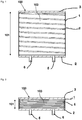
- the Figure 1 shows the principle of operation of a device according to the invention.
- the device has a reservoir 100 which has a rigid base 2 and a rigid cover 3 opposite the base 2.
- the base 2 and the cover 3 are connected to one another via a flexible, circumferential wall 1, so that said reservoir 100 is formed.
- the flexible wall 1 of the reservoir 100 is designed, for example, as a cylindrical tube made of thin plastic film.
- the tube 1 is closed at its ends by the rigid base 2 and a rigid cover 3.
- a spring 4 preferably in the form of a helical spring 4, is arranged in an interior 103 of the reservoir 100 and is pretensioned against the base and the cover so that it tries to move the base 2 and cover 3 apart.
- the bottom 2 and the lid 3 of the Reservoirs 100 are therefore opposite one another in the direction of movement 101 of the spring 4.
- the spring 4 is biased against the base 2 and the cover 3 in such a way that it is in the position shown in FIG Figure 1
- the fully expanded position shown (end position) is already compressed to preferably 50% to 70%, preferably 60% of its relaxed length.
- the spring 4 is completely compressed in its initial position. Your spring travel is therefore in particular used to 50% to 70% or 60%.
- the spring 4 is preferably also designed so that in the fully compressed position (cf. Fig. 2 ) the maximum possible spring force then generates the desired negative pressure.
- the negative pressure is 50% to 70% or 60% of the desired value.
- the negative pressure does not change between zero and 100%, but only between zero and 50% to 70% or between zero and 60%.
- the coils of the spring 4 furthermore prevent the reservoir 100, in particular the flexible wall 1, from collapsing when the reservoir 100 is compressed.
- the device or the reservoir 100 has a first connection 5, via which drained fluid can be sucked into the reservoir 100, and a second connection 6 via which said fluid can be withdrawn from the reservoir 100.
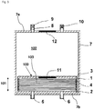
- FIG. 3 shows a further embodiment of a device according to the invention, in which the in the Figures 1 and 2 Reservoir 100 shown is arranged in a housing 7.
- the two connections 5 and 6 penetrate the housing 7 in this embodiment.
- the bottom 2 is connected to a wall 7b of the housing 7, whereas the cover 3 is movably arranged in an interior 102 of the housing 7.
- the housing 7 is also provided with a connection 8 in which a flow resistance 9 is arranged.
- valve 10 which, when opened, allows air to flow unhindered into the interior 102 of the housing 7 allowed, namely between the housing 7 and a wall 1, 3 of the reservoir 100 allowed.
- the device according to Fig. 3 preferably a magnet 11 which is arranged in the movable cover 3 of the reservoir 100, and a magnet 12 which is fixedly arranged in the wall 7a of the housing 7 opposite the cover 3.
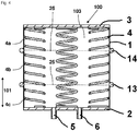
- the illustrated embodiment of the device or of the reservoir 100 uses a plurality of springs which are arranged between the edges of the base 2 and the cover 3.
- two expansion rings 13 and 14 are additionally preferably arranged on the circumferential wall 1, which prevent the collapse of the tubular reservoir 100, for example similar to a bellows or an accordion.
- one or more plates 25 can also be provided in the interior of the reservoir 100, which plates extend transversely to the springs 4 or to the direction of movement 101 and bear against the wall 1.
- Such plates 25 can be penetrated by the springs 4.
- the springs 4 can, however, also be divided accordingly, in which case the resulting spring sections 4a, 4b, 4c are supported on the then continuous plates 25.
- the plates 25 provided, for example, instead of the expanding rings 13, 14 are shown in FIG Figure 4 indicated with dashed lines.
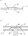
- FIG. 5 in detail a possible arrangement for tensioning the device, which can be used in all embodiments with housing 7.
- housing 7a of the housing 7 opposite the cover 3 an opening or bore 15 is arranged.
- a movable disk 16 is arranged in the interior 102 of the housing 7 and is connected to the wall 7 a of the housing 7 by an elastic membrane 17 or a bellows 17. If, as in Fig. 6 shown, the user has a finger 18 or a If a suitable object is inserted into the opening 15, he or she can press the disk 16 against the cover 3 and thus tension the device or its spring (s) 4.
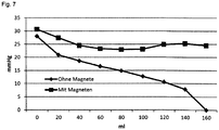
- FIG. 11 shows the course of the negative pressure in the reservoir 100 as a function of the volume sucked in by the device according to FIG Fig. 3 with and without magnets 11, 12.
Landscapes
- Health & Medical Sciences (AREA)
- Heart & Thoracic Surgery (AREA)
- Vascular Medicine (AREA)
- Engineering & Computer Science (AREA)
- Anesthesiology (AREA)
- Biomedical Technology (AREA)
- Hematology (AREA)
- Life Sciences & Earth Sciences (AREA)
- Animal Behavior & Ethology (AREA)
- General Health & Medical Sciences (AREA)
- Public Health (AREA)
- Veterinary Medicine (AREA)
- External Artificial Organs (AREA)
- Reciprocating Pumps (AREA)
Priority Applications (1)
| Application Number | Priority Date | Filing Date | Title |
|---|---|---|---|
| PL16726764T PL3302599T3 (pl) | 2015-06-02 | 2016-04-18 | Urządzenie do drenażu, w szczególności do drenażu przewlekłego krwiaka podtwardówkowego |
Applications Claiming Priority (2)
| Application Number | Priority Date | Filing Date | Title |
|---|---|---|---|
| DE102015108754.5A DE102015108754B8 (de) | 2015-06-02 | 2015-06-02 | Einrichtung zur Drainage, insbesondere zur Drainage eines chronischen subduralen Hämatoms |
| PCT/DE2016/100183 WO2016192705A1 (de) | 2015-06-02 | 2016-04-18 | Einrichtung zur drainage, insbesondere zur drainage eines chronischen subduralen hämatoms |
Publications (2)
| Publication Number | Publication Date |
|---|---|
| EP3302599A1 EP3302599A1 (de) | 2018-04-11 |
| EP3302599B1 true EP3302599B1 (de) | 2021-09-22 |
Family
ID=56097952
Family Applications (1)
| Application Number | Title | Priority Date | Filing Date |
|---|---|---|---|
| EP16726764.0A Active EP3302599B1 (de) | 2015-06-02 | 2016-04-18 | Einrichtung zur drainage, insbesondere zur drainage eines chronischen subduralen hämatoms |
Country Status (10)
| Country | Link |
|---|---|
| US (1) | US11065370B2 (enExample) |
| EP (1) | EP3302599B1 (enExample) |
| JP (1) | JP6774431B2 (enExample) |
| CN (1) | CN107666917B (enExample) |
| DE (1) | DE102015108754B8 (enExample) |
| ES (1) | ES2899223T3 (enExample) |
| HU (1) | HUE056758T2 (enExample) |
| PL (1) | PL3302599T3 (enExample) |
| PT (1) | PT3302599T (enExample) |
| WO (1) | WO2016192705A1 (enExample) |
Families Citing this family (3)
| Publication number | Priority date | Publication date | Assignee | Title |
|---|---|---|---|---|
| CN108969815B (zh) * | 2018-08-03 | 2020-11-03 | 吴联籽 | 一种用于腹部外科手术后的肛管排气装置 |
| NL2023563B1 (en) * | 2019-07-24 | 2021-02-10 | Heineken Supply Chain Bv | Pressure regulating system for a beverage container and beverage container provided therewith |
| CN111617325A (zh) * | 2020-05-28 | 2020-09-04 | 西安市儿童医院 | 基于胃肠、胸腹腔、及术后部位的医用减压引流装置 |
Family Cites Families (27)
| Publication number | Priority date | Publication date | Assignee | Title |
|---|---|---|---|---|
| NL95211C (enExample) * | 1956-03-02 | 1900-01-01 | ||
| US3115138A (en) * | 1960-07-14 | 1963-12-24 | Mcelvenny | Evacuator |
| US4141361A (en) * | 1970-02-09 | 1979-02-27 | Snyder Manufacturing Co., Incorporated | Evacuator |
| US3779243A (en) * | 1971-10-15 | 1973-12-18 | J Tussey | Contamination free surgical evacuator |
| US3939830A (en) * | 1975-03-10 | 1976-02-24 | Da Costa Harry | Manually operable dechoking and resuscitating device |
| US3991763A (en) * | 1975-04-17 | 1976-11-16 | Arbrook, Inc. | Surgical evacuator |
| US4278089A (en) | 1978-11-09 | 1981-07-14 | Howmedica, Inc. | Wound drainage device |
| US4429693A (en) * | 1980-09-16 | 1984-02-07 | Blake L W | Surgical fluid evacuator |
| US4578060A (en) * | 1983-07-20 | 1986-03-25 | Howmedica, Inc. | Wound drainage device |
| US4957487A (en) * | 1988-12-30 | 1990-09-18 | Baylor College Of Medicine | External male urinary catheter and collection system |
| IL93045A (en) * | 1990-01-12 | 1995-01-24 | Rosenberg Lior | A particularly usable vacuum device for removing wound fluid |
| JPH0836421A (ja) * | 1994-07-22 | 1996-02-06 | Fujikura Rubber Ltd | 磁石式減圧弁 |
| US5665070A (en) * | 1995-01-19 | 1997-09-09 | I-Flow Corporation | Infusion pump with magnetic bag compression |
| US5628305A (en) * | 1995-09-27 | 1997-05-13 | Richard J. Melker | Universal ventilation device |
| JPH09315593A (ja) * | 1996-05-24 | 1997-12-09 | Ricoh Co Ltd | 給紙用支持装置 |
| US6923799B1 (en) * | 1999-06-04 | 2005-08-02 | Wilson T. Asfora | Subdural evacuating port system |
| US7815616B2 (en) * | 2002-09-16 | 2010-10-19 | Boehringer Technologies, L.P. | Device for treating a wound |
| JP5192375B2 (ja) * | 2005-07-05 | 2013-05-08 | シー・アール・バード・インコーポレーテッド | 多機能モジュール式集尿システム |
| US20110238022A1 (en) * | 2010-03-24 | 2011-09-29 | Shayna Massi | Corporeal drainage system |
| US8795246B2 (en) * | 2010-08-10 | 2014-08-05 | Spiracur Inc. | Alarm system |
| US8753322B2 (en) * | 2010-08-10 | 2014-06-17 | Spiracur Inc. | Controlled negative pressure apparatus and alarm mechanism |
| CN102228722A (zh) * | 2011-06-13 | 2011-11-02 | 天津怡美医疗器械有限公司 | 预置负压与重力负压自动交替引流器 |
| KR101367004B1 (ko) | 2011-12-30 | 2014-02-24 | 김용찬 | 의료용 흡인기 |
| CN203303389U (zh) * | 2012-08-23 | 2013-11-27 | 程秀巧 | 一种医用引流器 |
| US9242077B2 (en) | 2013-03-12 | 2016-01-26 | DePuy Synthes Products, Inc. | Dynamic adjustment tool for programming an implantable valve |
| CA2915949C (en) * | 2013-07-12 | 2020-01-28 | Trudell Medical International | Huff cough simulation device |
| US20150300124A1 (en) * | 2015-07-07 | 2015-10-22 | Tejas Research & Engineering, Llc | Surface Controlled Downhole Valve with Supplemental Spring Closing Force for Ultra Deep Wells |
-
2015
- 2015-06-02 DE DE102015108754.5A patent/DE102015108754B8/de active Active
-
2016
- 2016-04-18 ES ES16726764T patent/ES2899223T3/es active Active
- 2016-04-18 PL PL16726764T patent/PL3302599T3/pl unknown
- 2016-04-18 HU HUE16726764A patent/HUE056758T2/hu unknown
- 2016-04-18 EP EP16726764.0A patent/EP3302599B1/de active Active
- 2016-04-18 US US15/579,017 patent/US11065370B2/en active Active
- 2016-04-18 JP JP2017562059A patent/JP6774431B2/ja active Active
- 2016-04-18 CN CN201680032464.8A patent/CN107666917B/zh active Active
- 2016-04-18 PT PT167267640T patent/PT3302599T/pt unknown
- 2016-04-18 WO PCT/DE2016/100183 patent/WO2016192705A1/de not_active Ceased
Also Published As
| Publication number | Publication date |
|---|---|
| HUE056758T2 (hu) | 2022-03-28 |
| PL3302599T3 (pl) | 2022-02-07 |
| EP3302599A1 (de) | 2018-04-11 |
| PT3302599T (pt) | 2021-11-03 |
| US11065370B2 (en) | 2021-07-20 |
| DE102015108754B3 (de) | 2016-09-08 |
| US20180140754A1 (en) | 2018-05-24 |
| JP6774431B2 (ja) | 2020-10-21 |
| WO2016192705A1 (de) | 2016-12-08 |
| DE102015108754B8 (de) | 2018-03-22 |
| ES2899223T3 (es) | 2022-03-10 |
| CN107666917A (zh) | 2018-02-06 |
| CN107666917B (zh) | 2021-11-09 |
| JP2018524048A (ja) | 2018-08-30 |
Similar Documents
| Publication | Publication Date | Title |
|---|---|---|
| EP0218785B1 (de) | Gerät zur Aufnahme und Reinfusion von Blut | |
| DE3441891C2 (enExample) | ||
| EP3113806B1 (de) | Katheter zum gerichteten leiten einer körperflüssigkeit | |
| DE69011631T2 (de) | Mikropumpe. | |
| DE69720744T2 (de) | Ventil zum gebrauch mit einer intravenösen vorrichtung | |
| CH709183A1 (de) | Thoraxdrainagevorrichtung. | |
| WO1988005319A1 (fr) | Dispositif pour aspirer les fluides des blessures | |
| EP3302599B1 (de) | Einrichtung zur drainage, insbesondere zur drainage eines chronischen subduralen hämatoms | |
| DE102007013492A1 (de) | Expansions-Fingergreifer | |
| DE2103187B2 (de) | Medizinische Wegwerfvorrichtung zum Absaugen von Flüssigkeiten | |
| WO2010121741A1 (de) | Ventilvorrichtung, ventileinsatz, externe funktionseinrichtung, behandlungsvorrichtung sowie verfahren | |
| WO1999022787A1 (de) | Infusionsgerät mit tropfkammer und schlauchklemme | |
| DE69910082T2 (de) | Infusionsvorrichtung | |
| DE112005001566T5 (de) | Einführungseinrichtung für endoluminale Eingriffe | |
| WO1989002764A1 (fr) | Agencement de clapet antiretour | |
| EP2885035B1 (de) | Einweg-ventileinrichtung | |
| EP4058699A1 (de) | Schwimmerventil, druckluftsystem mit einem schwimmerventil und trockner für ein druckluftsystem mit einem schwimmerventil | |
| WO1980002506A1 (fr) | Aiguille pour un dispositif de perfusion | |
| DE102011075029A1 (de) | Fluidhandhabungsvorrichtung mit Dichtvorrichtung | |
| DE69933308T2 (de) | Autotransfusionsbeutel mit hoher übertragungsrate | |
| DE102005003516B3 (de) | Blutentnahmereservoir | |
| DE202016100155U1 (de) | Unterdruckbehältnis | |
| DE3229253A1 (de) | Vakuumbetriebene pulsationspumpe | |
| EP0462422A1 (de) | Verfahren und Vorrichtung zum Reinigen des Blutes von Stoffwechselprodukten in einer Singel-Needle-Anordnung | |
| DE102004054496B4 (de) | Drainagekammer zur Aufnahme von Körperfluiden, insbesondere von Liquor |
Legal Events
| Date | Code | Title | Description |
|---|---|---|---|
| STAA | Information on the status of an ep patent application or granted ep patent |
Free format text: STATUS: THE INTERNATIONAL PUBLICATION HAS BEEN MADE |
|
| PUAI | Public reference made under article 153(3) epc to a published international application that has entered the european phase |
Free format text: ORIGINAL CODE: 0009012 |
|
| STAA | Information on the status of an ep patent application or granted ep patent |
Free format text: STATUS: REQUEST FOR EXAMINATION WAS MADE |
|
| 17P | Request for examination filed |
Effective date: 20171108 |
|
| AK | Designated contracting states |
Kind code of ref document: A1 Designated state(s): AL AT BE BG CH CY CZ DE DK EE ES FI FR GB GR HR HU IE IS IT LI LT LU LV MC MK MT NL NO PL PT RO RS SE SI SK SM TR |
|
| AX | Request for extension of the european patent |
Extension state: BA ME |
|
| DAV | Request for validation of the european patent (deleted) | ||
| DAX | Request for extension of the european patent (deleted) | ||
| GRAP | Despatch of communication of intention to grant a patent |
Free format text: ORIGINAL CODE: EPIDOSNIGR1 |
|
| STAA | Information on the status of an ep patent application or granted ep patent |
Free format text: STATUS: GRANT OF PATENT IS INTENDED |
|
| INTG | Intention to grant announced |
Effective date: 20210701 |
|
| RIN1 | Information on inventor provided before grant (corrected) |
Inventor name: SPIEGELBERG, ANDREAS |
|
| GRAS | Grant fee paid |
Free format text: ORIGINAL CODE: EPIDOSNIGR3 |
|
| GRAA | (expected) grant |
Free format text: ORIGINAL CODE: 0009210 |
|
| STAA | Information on the status of an ep patent application or granted ep patent |
Free format text: STATUS: THE PATENT HAS BEEN GRANTED |
|
| AK | Designated contracting states |
Kind code of ref document: B1 Designated state(s): AL AT BE BG CH CY CZ DE DK EE ES FI FR GB GR HR HU IE IS IT LI LT LU LV MC MK MT NL NO PL PT RO RS SE SI SK SM TR |
|
| REG | Reference to a national code |
Ref country code: GB Ref legal event code: FG4D Free format text: NOT ENGLISH |
|
| REG | Reference to a national code |
Ref country code: DE Ref legal event code: R096 Ref document number: 502016013875 Country of ref document: DE |
|
| REG | Reference to a national code |
Ref country code: IE Ref legal event code: FG4D Free format text: LANGUAGE OF EP DOCUMENT: GERMAN |
|
| REG | Reference to a national code |
Ref country code: CH Ref legal event code: EP Ref country code: AT Ref legal event code: REF Ref document number: 1431803 Country of ref document: AT Kind code of ref document: T Effective date: 20211015 |
|
| REG | Reference to a national code |
Ref country code: PT Ref legal event code: SC4A Ref document number: 3302599 Country of ref document: PT Date of ref document: 20211103 Kind code of ref document: T Free format text: AVAILABILITY OF NATIONAL TRANSLATION Effective date: 20211026 |
|
| REG | Reference to a national code |
Ref country code: NL Ref legal event code: FP |
|
| REG | Reference to a national code |
Ref country code: SE Ref legal event code: TRGR |
|
| REG | Reference to a national code |
Ref country code: LT Ref legal event code: MG9D |
|
| PG25 | Lapsed in a contracting state [announced via postgrant information from national office to epo] |
Ref country code: LT Free format text: LAPSE BECAUSE OF FAILURE TO SUBMIT A TRANSLATION OF THE DESCRIPTION OR TO PAY THE FEE WITHIN THE PRESCRIBED TIME-LIMIT Effective date: 20210922 Ref country code: BG Free format text: LAPSE BECAUSE OF FAILURE TO SUBMIT A TRANSLATION OF THE DESCRIPTION OR TO PAY THE FEE WITHIN THE PRESCRIBED TIME-LIMIT Effective date: 20211222 Ref country code: FI Free format text: LAPSE BECAUSE OF FAILURE TO SUBMIT A TRANSLATION OF THE DESCRIPTION OR TO PAY THE FEE WITHIN THE PRESCRIBED TIME-LIMIT Effective date: 20210922 Ref country code: HR Free format text: LAPSE BECAUSE OF FAILURE TO SUBMIT A TRANSLATION OF THE DESCRIPTION OR TO PAY THE FEE WITHIN THE PRESCRIBED TIME-LIMIT Effective date: 20210922 Ref country code: NO Free format text: LAPSE BECAUSE OF FAILURE TO SUBMIT A TRANSLATION OF THE DESCRIPTION OR TO PAY THE FEE WITHIN THE PRESCRIBED TIME-LIMIT Effective date: 20211222 Ref country code: RS Free format text: LAPSE BECAUSE OF FAILURE TO SUBMIT A TRANSLATION OF THE DESCRIPTION OR TO PAY THE FEE WITHIN THE PRESCRIBED TIME-LIMIT Effective date: 20210922 |
|
| PG25 | Lapsed in a contracting state [announced via postgrant information from national office to epo] |
Ref country code: LV Free format text: LAPSE BECAUSE OF FAILURE TO SUBMIT A TRANSLATION OF THE DESCRIPTION OR TO PAY THE FEE WITHIN THE PRESCRIBED TIME-LIMIT Effective date: 20210922 Ref country code: GR Free format text: LAPSE BECAUSE OF FAILURE TO SUBMIT A TRANSLATION OF THE DESCRIPTION OR TO PAY THE FEE WITHIN THE PRESCRIBED TIME-LIMIT Effective date: 20211223 |
|
| REG | Reference to a national code |
Ref country code: ES Ref legal event code: FG2A Ref document number: 2899223 Country of ref document: ES Kind code of ref document: T3 Effective date: 20220310 |
|
| REG | Reference to a national code |
Ref country code: HU Ref legal event code: AG4A Ref document number: E056758 Country of ref document: HU |
|
| PG25 | Lapsed in a contracting state [announced via postgrant information from national office to epo] |
Ref country code: IS Free format text: LAPSE BECAUSE OF FAILURE TO SUBMIT A TRANSLATION OF THE DESCRIPTION OR TO PAY THE FEE WITHIN THE PRESCRIBED TIME-LIMIT Effective date: 20220122 Ref country code: SK Free format text: LAPSE BECAUSE OF FAILURE TO SUBMIT A TRANSLATION OF THE DESCRIPTION OR TO PAY THE FEE WITHIN THE PRESCRIBED TIME-LIMIT Effective date: 20210922 Ref country code: RO Free format text: LAPSE BECAUSE OF FAILURE TO SUBMIT A TRANSLATION OF THE DESCRIPTION OR TO PAY THE FEE WITHIN THE PRESCRIBED TIME-LIMIT Effective date: 20210922 Ref country code: EE Free format text: LAPSE BECAUSE OF FAILURE TO SUBMIT A TRANSLATION OF THE DESCRIPTION OR TO PAY THE FEE WITHIN THE PRESCRIBED TIME-LIMIT Effective date: 20210922 Ref country code: CZ Free format text: LAPSE BECAUSE OF FAILURE TO SUBMIT A TRANSLATION OF THE DESCRIPTION OR TO PAY THE FEE WITHIN THE PRESCRIBED TIME-LIMIT Effective date: 20210922 Ref country code: AL Free format text: LAPSE BECAUSE OF FAILURE TO SUBMIT A TRANSLATION OF THE DESCRIPTION OR TO PAY THE FEE WITHIN THE PRESCRIBED TIME-LIMIT Effective date: 20210922 |
|
| REG | Reference to a national code |
Ref country code: DE Ref legal event code: R097 Ref document number: 502016013875 Country of ref document: DE |
|
| PG25 | Lapsed in a contracting state [announced via postgrant information from national office to epo] |
Ref country code: DK Free format text: LAPSE BECAUSE OF FAILURE TO SUBMIT A TRANSLATION OF THE DESCRIPTION OR TO PAY THE FEE WITHIN THE PRESCRIBED TIME-LIMIT Effective date: 20210922 |
|
| PLBE | No opposition filed within time limit |
Free format text: ORIGINAL CODE: 0009261 |
|
| STAA | Information on the status of an ep patent application or granted ep patent |
Free format text: STATUS: NO OPPOSITION FILED WITHIN TIME LIMIT |
|
| 26N | No opposition filed |
Effective date: 20220623 |
|
| PG25 | Lapsed in a contracting state [announced via postgrant information from national office to epo] |
Ref country code: SI Free format text: LAPSE BECAUSE OF FAILURE TO SUBMIT A TRANSLATION OF THE DESCRIPTION OR TO PAY THE FEE WITHIN THE PRESCRIBED TIME-LIMIT Effective date: 20210922 |
|
| REG | Reference to a national code |
Ref country code: BE Ref legal event code: MM Effective date: 20220430 |
|
| PG25 | Lapsed in a contracting state [announced via postgrant information from national office to epo] |
Ref country code: MC Free format text: LAPSE BECAUSE OF FAILURE TO SUBMIT A TRANSLATION OF THE DESCRIPTION OR TO PAY THE FEE WITHIN THE PRESCRIBED TIME-LIMIT Effective date: 20210922 Ref country code: LU Free format text: LAPSE BECAUSE OF NON-PAYMENT OF DUE FEES Effective date: 20220418 |
|
| PG25 | Lapsed in a contracting state [announced via postgrant information from national office to epo] |
Ref country code: BE Free format text: LAPSE BECAUSE OF NON-PAYMENT OF DUE FEES Effective date: 20220430 |
|
| PG25 | Lapsed in a contracting state [announced via postgrant information from national office to epo] |
Ref country code: IE Free format text: LAPSE BECAUSE OF NON-PAYMENT OF DUE FEES Effective date: 20220418 |
|
| PGFP | Annual fee paid to national office [announced via postgrant information from national office to epo] |
Ref country code: TR Payment date: 20230306 Year of fee payment: 8 |
|
| PG25 | Lapsed in a contracting state [announced via postgrant information from national office to epo] |
Ref country code: SM Free format text: LAPSE BECAUSE OF FAILURE TO SUBMIT A TRANSLATION OF THE DESCRIPTION OR TO PAY THE FEE WITHIN THE PRESCRIBED TIME-LIMIT Effective date: 20210922 Ref country code: MK Free format text: LAPSE BECAUSE OF FAILURE TO SUBMIT A TRANSLATION OF THE DESCRIPTION OR TO PAY THE FEE WITHIN THE PRESCRIBED TIME-LIMIT Effective date: 20210922 Ref country code: CY Free format text: LAPSE BECAUSE OF FAILURE TO SUBMIT A TRANSLATION OF THE DESCRIPTION OR TO PAY THE FEE WITHIN THE PRESCRIBED TIME-LIMIT Effective date: 20210922 |
|
| PG25 | Lapsed in a contracting state [announced via postgrant information from national office to epo] |
Ref country code: MT Free format text: LAPSE BECAUSE OF FAILURE TO SUBMIT A TRANSLATION OF THE DESCRIPTION OR TO PAY THE FEE WITHIN THE PRESCRIBED TIME-LIMIT Effective date: 20210922 |
|
| PGFP | Annual fee paid to national office [announced via postgrant information from national office to epo] |
Ref country code: NL Payment date: 20250424 Year of fee payment: 10 |
|
| PGFP | Annual fee paid to national office [announced via postgrant information from national office to epo] |
Ref country code: PL Payment date: 20250423 Year of fee payment: 10 Ref country code: DE Payment date: 20250423 Year of fee payment: 10 |
|
| PGFP | Annual fee paid to national office [announced via postgrant information from national office to epo] |
Ref country code: ES Payment date: 20250502 Year of fee payment: 10 Ref country code: GB Payment date: 20250501 Year of fee payment: 10 |
|
| PGFP | Annual fee paid to national office [announced via postgrant information from national office to epo] |
Ref country code: HU Payment date: 20250425 Year of fee payment: 10 |
|
| PGFP | Annual fee paid to national office [announced via postgrant information from national office to epo] |
Ref country code: IT Payment date: 20250424 Year of fee payment: 10 |
|
| PGFP | Annual fee paid to national office [announced via postgrant information from national office to epo] |
Ref country code: PT Payment date: 20250429 Year of fee payment: 10 |
|
| PGFP | Annual fee paid to national office [announced via postgrant information from national office to epo] |
Ref country code: FR Payment date: 20250430 Year of fee payment: 10 |
|
| PGFP | Annual fee paid to national office [announced via postgrant information from national office to epo] |
Ref country code: CH Payment date: 20250501 Year of fee payment: 10 |
|
| PGFP | Annual fee paid to national office [announced via postgrant information from national office to epo] |
Ref country code: AT Payment date: 20250423 Year of fee payment: 10 |
|
| PGFP | Annual fee paid to national office [announced via postgrant information from national office to epo] |
Ref country code: SE Payment date: 20250424 Year of fee payment: 10 |