EP3302013B1 - Schiebbare montageklammer am chassis - Google Patents
Schiebbare montageklammer am chassis Download PDFInfo
- Publication number
- EP3302013B1 EP3302013B1 EP17172069.1A EP17172069A EP3302013B1 EP 3302013 B1 EP3302013 B1 EP 3302013B1 EP 17172069 A EP17172069 A EP 17172069A EP 3302013 B1 EP3302013 B1 EP 3302013B1
- Authority
- EP
- European Patent Office
- Prior art keywords
- rack
- server
- mounting flange
- mounting bracket
- chassis
- Prior art date
- Legal status (The legal status is an assumption and is not a legal conclusion. Google has not performed a legal analysis and makes no representation as to the accuracy of the status listed.)
- Active
Links
Images


Classifications
-
- H—ELECTRICITY
- H05—ELECTRIC TECHNIQUES NOT OTHERWISE PROVIDED FOR
- H05K—PRINTED CIRCUITS; CASINGS OR CONSTRUCTIONAL DETAILS OF ELECTRIC APPARATUS; MANUFACTURE OF ASSEMBLAGES OF ELECTRICAL COMPONENTS
- H05K7/00—Constructional details common to different types of electric apparatus
- H05K7/14—Mounting supporting structure in casing or on frame or rack
- H05K7/1485—Servers; Data center rooms, e.g. 19-inch computer racks
- H05K7/1488—Cabinets therefor, e.g. chassis or racks or mechanical interfaces between blades and support structures
- H05K7/1489—Cabinets therefor, e.g. chassis or racks or mechanical interfaces between blades and support structures characterized by the mounting of blades therein, e.g. brackets, rails, trays
-
- F—MECHANICAL ENGINEERING; LIGHTING; HEATING; WEAPONS; BLASTING
- F16—ENGINEERING ELEMENTS AND UNITS; GENERAL MEASURES FOR PRODUCING AND MAINTAINING EFFECTIVE FUNCTIONING OF MACHINES OR INSTALLATIONS; THERMAL INSULATION IN GENERAL
- F16M—FRAMES, CASINGS OR BEDS OF ENGINES, MACHINES OR APPARATUS, NOT SPECIFIC TO ENGINES, MACHINES OR APPARATUS PROVIDED FOR ELSEWHERE; STANDS; SUPPORTS
- F16M13/00—Other supports for positioning apparatus or articles; Means for steadying hand-held apparatus or articles
- F16M13/02—Other supports for positioning apparatus or articles; Means for steadying hand-held apparatus or articles for supporting on, or attaching to, an object, e.g. tree, gate, window-frame, cycle
-
- A—HUMAN NECESSITIES
- A47—FURNITURE; DOMESTIC ARTICLES OR APPLIANCES; COFFEE MILLS; SPICE MILLS; SUCTION CLEANERS IN GENERAL
- A47B—TABLES; DESKS; OFFICE FURNITURE; CABINETS; DRAWERS; GENERAL DETAILS OF FURNITURE
- A47B96/00—Details of cabinets, racks or shelf units not covered by a single one of groups A47B43/00 - A47B95/00; General details of furniture
- A47B96/06—Brackets or similar supporting means for cabinets, racks or shelves
- A47B96/066—Supporting means received within an edge of the shelf
-
- A—HUMAN NECESSITIES
- A47—FURNITURE; DOMESTIC ARTICLES OR APPLIANCES; COFFEE MILLS; SPICE MILLS; SUCTION CLEANERS IN GENERAL
- A47B—TABLES; DESKS; OFFICE FURNITURE; CABINETS; DRAWERS; GENERAL DETAILS OF FURNITURE
- A47B96/00—Details of cabinets, racks or shelf units not covered by a single one of groups A47B43/00 - A47B95/00; General details of furniture
- A47B96/06—Brackets or similar supporting means for cabinets, racks or shelves
- A47B96/07—Brackets or similar supporting means for cabinets, racks or shelves adjustable in themselves
Definitions
- the present invention relates to a slidable mounting bracket, and more specifically to a slidable mounting bracket on server or switch chassis.
- Switch/Server chassis which are installed on racks, are conventionally installed and removed from the same side of the rack. That is, if a server/switch chassis is installed from the front of a rack, it can only be removed from the front of the rack.
- the traditional bracket design of the server/switch chassis is limiting and does not allow the server/switch chassis to go through the rack. Therefore, there is a need for a bracket that can allow server/switch chassis to be installed from one side of the rack and be removed from the other side, thereby allowing the server/switch chassis to be able to pass through the rack and improving convenience of service and reducing service time.
- US 2014/0111070 A1 describes side panels that are secured to the posts on opposing sides of a server rack, that include a plurality of slots that are used to support rack-mounted equipment. Sides of a chassis including computing device chassis include protruding pins that can be extended into the slots in the opposing panels.
- a mounting bracket Design for such a bracket, with its different example, is illustrated in Figs. 1A-5B .
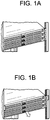
- Fig. 1 depicts the conventional mounting bracket used on switch/server chassis, according to an example.
- Fig. 1A conventional mounting brackets connected to the server/switch chassis is used to connect chassis with the rack. It is clear that the chassis can move in and out of the rack only from one side of the rack.
- Fig. 1B further depicts an example where the bracket sits flush with the rack and can be locked with the rack using a screw/washer.
- the figure clearly depicts the downside of the conventional mounting brackets, limiting the movement of the chassis to only one side of the rack.
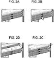
- Figs. 2A-2D depict a rotatable mounting bracket on a server/switch chassis interacting with a rack, according to an example.
- Fig. 2A depicts an example of the rotatable mounting bracket, where the bracket sits flush with the rack, in turn locking the chassis in place with the rack.
- Fig. 2B depicts an example where the rotatable mounting bracket is rotated to move towards the server/switch, thereby no longer obstructing the motion of the server/switch chassis in and out of the rack from either side of the rack.
- Fig. 2C depicts the rotatable mounting brackets completely rotated with the server/switch chassis in a condition to be moved out of the rack.
- Fig. 2D depicts an example of the server/switch chassis being moved out of the rack from the back side of the rack, with the rotatable mounting bracket not obstructing such motion by having been rotated and moved out of the way of the rack.
- Figs. 3A and 3B depict an example of a rotatable mounting bracket, as seen from the top view of the rack.
- the rotatable mounting bracket depicts a member portion 301, which connects with a portion of the server/switch chassis 305 via screws, bolts or other fasteners.
- the member portion 301 may have openings (not shown) which correspond to openings on server/switch chassis 305, which may be used to fasten the member portion 301 to the server/switch chassis 305.
- the rotatable mounting bracket further incorporates a mounting flange 303 which connects to a mounting portion of the rack 304.
- the rack 304 is depicted from the top view as being connected to the mounting flange 303.
- the connection between the mounting flange 303 and the mounting portion of the rack 304 may be made via screws, bolts or other fasteners.
- the mounting flange 303 may have openings (not shown) which correspond to openings on the rack 304, which may be used to fasten the mounting flange 303 to the rack 304.
- the mounting bracket further incorporates a locking mechanism 306 located on the mounting flange 303 and an unlocking plug 307 located on the mounting flange 303, wherein the locking mechanism 306 locks the mounting bracket to the rack 304 when the mounting flange 303 comes in contact with the rack 304 and the unlocking plug 307 unlocks the mounting bracket from the panel when the unlocking plug 307 is pressed.
- the pivoting mechanism 302 connects the member portion 301 and the mounting flange 303.
- the mounting flange 303 can be rotated along the pivoting mechanism 302 to move out of the way of the rack towards the server/switch chassis, as shown in Fig. 3B .
- Such a movement of the mounting flange 303 allows for free movement of the chassis in and out of the rack from either side of the rack 304, without any concern that the mounting flange 303 will interfere with the rack 304.
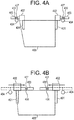
- Figs. 4A and 4B depict an embodiment of a slidable mounting bracket, as shown from the top view of the rack.
- the slidable mounting bracket depicts a member portion 401, which connects with a portion of the server/switch chassis 405 via screws, bolts or other fasteners.
- the member portion 401 may have openings (not shown) which correspond to openings on server/switch chassis 405, which may be used to fasten the member portion 401 to the server/switch chassis 405.
- the slidable mounting bracket further incorporates a mounting flange 403 which connects to a sliding mechanism 402.
- the rack 404 is depicted from the top view as being connected to the mounting flange 403.
- the connection between the mounting flange 403 and the mounting portion of the rack 404 may be made via screws, bolts or other fasteners.
- the mounting flange 403 may have openings (not shown) which correspond to openings on the rack 404, which may be used to fasten the mounting flange 403 to the rack 404.
- the mounting bracket further incorporates a locking mechanism 406 located on the mounting flange 403 and an unlocking plug 407 located on the mounting flange 403, wherein the locking mechanism 406 locks the mounting bracket to the rack 404 when the mounting flange 403 comes in contact with the rack 404 and the unlocking plug 407 unlocks the mounting bracket from the panel when the unlocking plug 407 is pressed.
- the sliding mechanism 402 connects the member portion 401 and the mounting flange 403.
- the mounting flange 403 can slide along the sliding mechanism 402 to move out of the way of the rack 404 and towards the server/switch chassis 405, as shown in Fig. 4B .
- Such a movement of the mounting flange 403, as is shown using the arrow and the dotted positioning, allows for free movement of the chassis in and out of the rack from either side of the rack 404, without any concern that the mounting flange 403 will interfere with the rack 404.
- Figs. 5A and 5B depict another example of a rotatable mounting bracket, as shown from the front view of the rack.
- the rotatable mounting bracket depicts a member portion 501, which connects with a portion of the server/switch chassis 505 via screws, bolts or other fasteners.
- the member portion 501 may have openings (not shown) which correspond to openings on server/switch chassis 505, which may be used to fasten the member portion 301 to the server/switch chassis 505.
- the rotatable mounting bracket further incorporates a mounting flange 503 which connects to a mounting portion of the rack 504.
- the rack 504 is depicted from the front view as being connected to the mounting flange 503.
- the connection between the mounting flange 503 and the mounting portion of the rack 504 may be made via screws, bolts or other fasteners.
- the mounting flange 503 may have openings (not shown) which correspond to openings on the rack 504, which may be used to fasten the mounting flange 503 to the rack 504.
- the mounting bracket further incorporates a locking mechanism 506 located on the mounting flange 503 and an unlocking plug 507 located on the mounting flange 503, wherein the locking mechanism 506 locks the mounting bracket to the rack 504 when the mounting flange 503 comes in contact with the rack 504 and the unlocking plug 507 unlocks the mounting bracket from the panel when the unlocking plug 507 is pressed.
- the rotational mechanism 502 connects the member portion 501 and the mounting flange 503.
- the mounting flange 503 can rotate along the rotational mechanism 502 to move out of the way of the rack 504 and towards the server/switch chassis 505, as shown in Fig. 5B .
- Such a movement of the mounting flange 503, as is shown using the arrow and the dotted positioning, allows for free movement of the chassis in and out of the rack from either side of the rack 504, without any concern that the mounting flange 503 will interfere with the rack 504.
- the rotatable mounting bracket may further incorporate a reinforcement mechanism which prevents the mounting flange and the member portion from flailing around when not fastened with the rack or the server/switch chassis.
- a reinforcement mechanism may be a spring loaded mechanism, according to an example.
- the reinforcement mechanism may further be incorporated into the pivoting mechanism, sliding mechanism or the rotational mechanism, as described above, or may be implemented as a free standing portion.
- the reinforcement mechanism may further use screws, bolts or other fastening means to fasten the member portion and the mounting flange so as not to flail around when not in contact with the rack or the server/switch chassis.
- the reinforcement mechanism may be free standing as well, proving support to the member portion and the mounting flange without use of external elements.
Landscapes
- Engineering & Computer Science (AREA)
- General Engineering & Computer Science (AREA)
- Computer Hardware Design (AREA)
- Microelectronics & Electronic Packaging (AREA)
- Mechanical Engineering (AREA)
- Cooling Or The Like Of Electrical Apparatus (AREA)
- Drawers Of Furniture (AREA)
- Casings For Electric Apparatus (AREA)
- Mounting Of Printed Circuit Boards And The Like (AREA)
- Pivots And Pivotal Connections (AREA)
Claims (3)
- Montagehalterung zum Montieren eines Server/Switch-Chassis (405) an ein Rack (404), wobei das Server/Switch-Chassis (405) eine Vorderseite, eine Rückseite und zwei zwischen der Vorderseite und der Rückseite miteinander verbundene laterale Seiten aufweist, dadurch gekennzeichnet, dass die Montagehalterung Folgendes umfasst:einen Montageflansch (403),zwei Gliedabschnitte (401), die mit den jeweiligen lateralen Seiten des Server/Switch-Chassis (405) verbunden sind, undeinen Schiebemechanismus (402), der mit einem der beiden Gliedabschnitte (401) und dem Montageflansch (403) verbunden ist, wobeider Schiebemechanismus (402) mit der Vorderseite des Server/Switch-Chassis (405) verbunden ist,der Montageflansch (403) dazu ausgestaltet ist, entlang des Schiebemechanismus (402) zu gleiten, um sich von einer ersten Seite des Racks (404) zu einer zweiten Seite des Racks (404) zu bewegen,wobei das Server/Switch-Chassis (405), wenn der Montageflansch (403) entlang des Schiebemechanismus (402) zu der ersten Seite des Racks (404) gleitet, in einer ersten Richtung in das Rack (404) eingeführt und in einer zweiten Richtung aus dem Rack (404) entfernt wird, wobei die erste Richtung und die zweite Richtung entgegengesetzt sind, undwobei das Server/Switch-Chassis (405), wenn der Montageflansch (403) entlang des Schiebemechanismus (402) zu der zweiten Seite des Racks (404) gleitet, in der zweiten Richtung in das Rack (404) eingeführt und in der ersten Richtung aus dem Rack (404) entfernt wird.
- Montagehalterung nach Anspruch 1, dadurch gekennzeichnet, dass der Montageflansch (403) dazu ausgestaltet ist, entlang des Schiebemechanismus zu gleiten, um den einen der beiden Gliedabschnitte (401) zu überlappen.
- Montagehalterung nach einem der vorhergehenden Ansprüche, dadurch gekennzeichnet, dass sie ferner Folgendes umfasst:einen Verriegelungsmechanismus (406), der an dem Montageflansch (403) angeordnet ist, undeinen Entriegelungstopfen (407), der an dem Montageflansch (403) angeordnet ist, wobeider Verriegelungsmechanismus (406) die Montagehalterung an das Rack (404) verriegelt, wenn der Montageflansch (403) mit dem Rack (404) in Kontakt kommt, undder Entriegelungstopfen (407) die Montagehalterung von einer Platte entriegelt, wenn der Entriegelungstopfen (407) niedergedrückt wird.
Applications Claiming Priority (2)
| Application Number | Priority Date | Filing Date | Title |
|---|---|---|---|
| US201662402333P | 2016-09-30 | 2016-09-30 | |
| US15/409,304 US10321599B2 (en) | 2016-09-30 | 2017-01-18 | Rotatable mounting bracket on chassis |
Publications (2)
| Publication Number | Publication Date |
|---|---|
| EP3302013A1 EP3302013A1 (de) | 2018-04-04 |
| EP3302013B1 true EP3302013B1 (de) | 2021-10-20 |
Family
ID=58745122
Family Applications (1)
| Application Number | Title | Priority Date | Filing Date |
|---|---|---|---|
| EP17172069.1A Active EP3302013B1 (de) | 2016-09-30 | 2017-05-19 | Schiebbare montageklammer am chassis |
Country Status (5)
| Country | Link |
|---|---|
| US (1) | US10321599B2 (de) |
| EP (1) | EP3302013B1 (de) |
| JP (1) | JP6491702B2 (de) |
| CN (1) | CN107883134B (de) |
| TW (1) | TWI624211B (de) |
Families Citing this family (6)
| Publication number | Priority date | Publication date | Assignee | Title |
|---|---|---|---|---|
| TWI639377B (zh) * | 2017-12-18 | 2018-10-21 | 川湖科技股份有限公司 | 應用在機架系統的支撐總成 |
| JP6769509B2 (ja) | 2019-03-27 | 2020-10-14 | 日本電気株式会社 | ラックマウント型電子機器 |
| CN111596741B (zh) * | 2020-05-29 | 2023-08-04 | 英业达科技有限公司 | 伺服器机壳 |
| JP7479949B2 (ja) | 2020-06-12 | 2024-05-09 | 日本通信電材株式会社 | 光部品収容箱 |
| US11395435B2 (en) * | 2020-08-20 | 2022-07-19 | King Slide Works Co., Ltd. | Slide rail assembly |
| US12250784B2 (en) * | 2022-12-20 | 2025-03-11 | Microsoft Technology Licensing, Llc | Equipment locking device |
Family Cites Families (18)
| Publication number | Priority date | Publication date | Assignee | Title |
|---|---|---|---|---|
| US6398041B1 (en) | 1999-12-03 | 2002-06-04 | Hewlett-Packard Company | Snap system for retaining slide mounted rack system into multiple racks without tools |
| JP2002368462A (ja) * | 2001-06-05 | 2002-12-20 | Matsushita Electric Ind Co Ltd | 卓上及びラック搭載両用電気機器収容筐体装置 |
| TWI255688B (en) | 2004-06-23 | 2006-05-21 | Asustek Comp Inc | Electronic apparatus with rotatable element for fixing |
| JP4334438B2 (ja) * | 2004-08-20 | 2009-09-30 | 富士通株式会社 | 着脱装置、ユニット及びそれを有する電子機器 |
| US20080135705A1 (en) * | 2006-12-12 | 2008-06-12 | Inventec Corporation | Fixing bracket |
| US7857267B2 (en) | 2007-06-13 | 2010-12-28 | Alcatel Lucent | Unique mounting for computer equipment in frames |
| SE534247C2 (sv) * | 2009-10-23 | 2011-06-14 | Clamco Invest Ab | Hölje för elektronisk utrustning, innefattande fästanordning |
| TW201117703A (en) * | 2009-11-04 | 2011-05-16 | Inventec Corp | Rail apparatus and server |
| JP5454316B2 (ja) | 2010-04-07 | 2014-03-26 | 富士通株式会社 | ラック |
| TW201249310A (en) | 2011-05-18 | 2012-12-01 | Hon Hai Prec Ind Co Ltd | Fixing apparatus for slide rail |
| TW201325395A (zh) | 2011-12-15 | 2013-06-16 | Inventec Corp | 鎖扣結構與應用其之伺服器 |
| TWI548329B (zh) * | 2012-06-07 | 2016-09-01 | Tseng Ching Chao | Active ear holder and equipment auxiliary replacement device |
| CN103533799B (zh) | 2012-07-06 | 2016-08-17 | 曾庆照 | 活动耳架及包含该活动耳架的器材辅助更换装置 |
| US20140111070A1 (en) * | 2012-10-22 | 2014-04-24 | Jon Brian Ehlen | Universally configurable rack mount side panels |
| JP2015153858A (ja) | 2014-02-13 | 2015-08-24 | 富士通テレコムネットワークス株式会社 | 装置の取付具 |
| CN205372009U (zh) * | 2015-12-18 | 2016-07-06 | 江苏斯菲尔电气股份有限公司 | 电子装置固定支架 |
| CN205304829U (zh) * | 2016-01-25 | 2016-06-08 | 珠海大横琴科技发展有限公司 | 交换机 |
| US9769947B1 (en) * | 2016-03-21 | 2017-09-19 | Oracle International Corporation | Cable management for rack-mounted computing devices |
-
2017
- 2017-01-18 US US15/409,304 patent/US10321599B2/en active Active
- 2017-03-23 TW TW106109809A patent/TWI624211B/zh active
- 2017-04-13 CN CN201710239089.0A patent/CN107883134B/zh active Active
- 2017-05-19 EP EP17172069.1A patent/EP3302013B1/de active Active
- 2017-07-04 JP JP2017130888A patent/JP6491702B2/ja active Active
Non-Patent Citations (1)
| Title |
|---|
| None * |
Also Published As
| Publication number | Publication date |
|---|---|
| US10321599B2 (en) | 2019-06-11 |
| JP2018060518A (ja) | 2018-04-12 |
| EP3302013A1 (de) | 2018-04-04 |
| US20180098454A1 (en) | 2018-04-05 |
| CN107883134B (zh) | 2020-05-12 |
| CN107883134A (zh) | 2018-04-06 |
| TWI624211B (zh) | 2018-05-11 |
| JP6491702B2 (ja) | 2019-03-27 |
| TW201815256A (zh) | 2018-04-16 |
Similar Documents
| Publication | Publication Date | Title |
|---|---|---|
| EP3302013A1 (de) | Drehbaren montageklammer am chassis | |
| US10251482B2 (en) | Bracket device | |
| US8988821B2 (en) | Hard disk drive enclosure | |
| US10405451B2 (en) | Zero-U rack keyboard and monitor | |
| US20140211433A1 (en) | Circuit board mounting assembly | |
| US20130026113A1 (en) | Server rack with lockable slide assembly | |
| US20180070724A1 (en) | Bracket device | |
| CN102404949A (zh) | 服务器机柜 | |
| US20210198926A1 (en) | Integrated latch mechanism for securing rackmount equipment in a chassis | |
| US20170340109A1 (en) | Slide rail device | |
| US20120056516A1 (en) | Server rack | |
| US8446720B2 (en) | Mounting apparatus for expansion card | |
| US20140076829A1 (en) | Rack for electronic apparatus | |
| US8498119B2 (en) | Electronic device access door | |
| US20120320519A1 (en) | Storage device assembly | |
| US8240627B2 (en) | Retaining assembly for locking disk drive | |
| US7360659B1 (en) | Space-saving mounting fixture for use with an equipment rack | |
| US8837158B2 (en) | Electronic device with blocking mechanism | |
| US10722026B2 (en) | Slide rail assembly and bracket device thereof | |
| US8723058B2 (en) | Mounting apparatus and electronic device enclosure with the same | |
| US20130099643A1 (en) | Double Hinge Assembly | |
| US20160312496A1 (en) | Locking device | |
| US8757738B2 (en) | Mechanism for closing sliding doors | |
| CN208385262U (zh) | 高压柜体的联锁装置 | |
| US20130094899A1 (en) | Locking apparatus |
Legal Events
| Date | Code | Title | Description |
|---|---|---|---|
| PUAI | Public reference made under article 153(3) epc to a published international application that has entered the european phase |
Free format text: ORIGINAL CODE: 0009012 |
|
| STAA | Information on the status of an ep patent application or granted ep patent |
Free format text: STATUS: THE APPLICATION HAS BEEN PUBLISHED |
|
| AK | Designated contracting states |
Kind code of ref document: A1 Designated state(s): AL AT BE BG CH CY CZ DE DK EE ES FI FR GB GR HR HU IE IS IT LI LT LU LV MC MK MT NL NO PL PT RO RS SE SI SK SM TR |
|
| AX | Request for extension of the european patent |
Extension state: BA ME |
|
| STAA | Information on the status of an ep patent application or granted ep patent |
Free format text: STATUS: REQUEST FOR EXAMINATION WAS MADE |
|
| 17P | Request for examination filed |
Effective date: 20180604 |
|
| RBV | Designated contracting states (corrected) |
Designated state(s): AL AT BE BG CH CY CZ DE DK EE ES FI FR GB GR HR HU IE IS IT LI LT LU LV MC MK MT NL NO PL PT RO RS SE SI SK SM TR |
|
| STAA | Information on the status of an ep patent application or granted ep patent |
Free format text: STATUS: EXAMINATION IS IN PROGRESS |
|
| 17Q | First examination report despatched |
Effective date: 20200921 |
|
| GRAP | Despatch of communication of intention to grant a patent |
Free format text: ORIGINAL CODE: EPIDOSNIGR1 |
|
| STAA | Information on the status of an ep patent application or granted ep patent |
Free format text: STATUS: GRANT OF PATENT IS INTENDED |
|
| INTG | Intention to grant announced |
Effective date: 20210528 |
|
| GRAS | Grant fee paid |
Free format text: ORIGINAL CODE: EPIDOSNIGR3 |
|
| GRAA | (expected) grant |
Free format text: ORIGINAL CODE: 0009210 |
|
| STAA | Information on the status of an ep patent application or granted ep patent |
Free format text: STATUS: THE PATENT HAS BEEN GRANTED |
|
| AK | Designated contracting states |
Kind code of ref document: B1 Designated state(s): AL AT BE BG CH CY CZ DE DK EE ES FI FR GB GR HR HU IE IS IT LI LT LU LV MC MK MT NL NO PL PT RO RS SE SI SK SM TR |
|
| REG | Reference to a national code |
Ref country code: GB Ref legal event code: FG4D |
|
| REG | Reference to a national code |
Ref country code: CH Ref legal event code: EP |
|
| REG | Reference to a national code |
Ref country code: IE Ref legal event code: FG4D |
|
| REG | Reference to a national code |
Ref country code: DE Ref legal event code: R096 Ref document number: 602017047785 Country of ref document: DE |
|
| REG | Reference to a national code |
Ref country code: AT Ref legal event code: REF Ref document number: 1440986 Country of ref document: AT Kind code of ref document: T Effective date: 20211115 |
|
| REG | Reference to a national code |
Ref country code: LT Ref legal event code: MG9D |
|
| REG | Reference to a national code |
Ref country code: NL Ref legal event code: MP Effective date: 20211020 |
|
| REG | Reference to a national code |
Ref country code: AT Ref legal event code: MK05 Ref document number: 1440986 Country of ref document: AT Kind code of ref document: T Effective date: 20211020 |
|
| PG25 | Lapsed in a contracting state [announced via postgrant information from national office to epo] |
Ref country code: RS Free format text: LAPSE BECAUSE OF FAILURE TO SUBMIT A TRANSLATION OF THE DESCRIPTION OR TO PAY THE FEE WITHIN THE PRESCRIBED TIME-LIMIT Effective date: 20211020 Ref country code: LT Free format text: LAPSE BECAUSE OF FAILURE TO SUBMIT A TRANSLATION OF THE DESCRIPTION OR TO PAY THE FEE WITHIN THE PRESCRIBED TIME-LIMIT Effective date: 20211020 Ref country code: FI Free format text: LAPSE BECAUSE OF FAILURE TO SUBMIT A TRANSLATION OF THE DESCRIPTION OR TO PAY THE FEE WITHIN THE PRESCRIBED TIME-LIMIT Effective date: 20211020 Ref country code: BG Free format text: LAPSE BECAUSE OF FAILURE TO SUBMIT A TRANSLATION OF THE DESCRIPTION OR TO PAY THE FEE WITHIN THE PRESCRIBED TIME-LIMIT Effective date: 20220120 Ref country code: AT Free format text: LAPSE BECAUSE OF FAILURE TO SUBMIT A TRANSLATION OF THE DESCRIPTION OR TO PAY THE FEE WITHIN THE PRESCRIBED TIME-LIMIT Effective date: 20211020 |
|
| PG25 | Lapsed in a contracting state [announced via postgrant information from national office to epo] |
Ref country code: IS Free format text: LAPSE BECAUSE OF FAILURE TO SUBMIT A TRANSLATION OF THE DESCRIPTION OR TO PAY THE FEE WITHIN THE PRESCRIBED TIME-LIMIT Effective date: 20220220 Ref country code: SE Free format text: LAPSE BECAUSE OF FAILURE TO SUBMIT A TRANSLATION OF THE DESCRIPTION OR TO PAY THE FEE WITHIN THE PRESCRIBED TIME-LIMIT Effective date: 20211020 Ref country code: PT Free format text: LAPSE BECAUSE OF FAILURE TO SUBMIT A TRANSLATION OF THE DESCRIPTION OR TO PAY THE FEE WITHIN THE PRESCRIBED TIME-LIMIT Effective date: 20220221 Ref country code: PL Free format text: LAPSE BECAUSE OF FAILURE TO SUBMIT A TRANSLATION OF THE DESCRIPTION OR TO PAY THE FEE WITHIN THE PRESCRIBED TIME-LIMIT Effective date: 20211020 Ref country code: NO Free format text: LAPSE BECAUSE OF FAILURE TO SUBMIT A TRANSLATION OF THE DESCRIPTION OR TO PAY THE FEE WITHIN THE PRESCRIBED TIME-LIMIT Effective date: 20220120 Ref country code: NL Free format text: LAPSE BECAUSE OF FAILURE TO SUBMIT A TRANSLATION OF THE DESCRIPTION OR TO PAY THE FEE WITHIN THE PRESCRIBED TIME-LIMIT Effective date: 20211020 Ref country code: LV Free format text: LAPSE BECAUSE OF FAILURE TO SUBMIT A TRANSLATION OF THE DESCRIPTION OR TO PAY THE FEE WITHIN THE PRESCRIBED TIME-LIMIT Effective date: 20211020 Ref country code: HR Free format text: LAPSE BECAUSE OF FAILURE TO SUBMIT A TRANSLATION OF THE DESCRIPTION OR TO PAY THE FEE WITHIN THE PRESCRIBED TIME-LIMIT Effective date: 20211020 Ref country code: GR Free format text: LAPSE BECAUSE OF FAILURE TO SUBMIT A TRANSLATION OF THE DESCRIPTION OR TO PAY THE FEE WITHIN THE PRESCRIBED TIME-LIMIT Effective date: 20220121 Ref country code: ES Free format text: LAPSE BECAUSE OF FAILURE TO SUBMIT A TRANSLATION OF THE DESCRIPTION OR TO PAY THE FEE WITHIN THE PRESCRIBED TIME-LIMIT Effective date: 20211020 |
|
| REG | Reference to a national code |
Ref country code: DE Ref legal event code: R097 Ref document number: 602017047785 Country of ref document: DE |
|
| PG25 | Lapsed in a contracting state [announced via postgrant information from national office to epo] |
Ref country code: SM Free format text: LAPSE BECAUSE OF FAILURE TO SUBMIT A TRANSLATION OF THE DESCRIPTION OR TO PAY THE FEE WITHIN THE PRESCRIBED TIME-LIMIT Effective date: 20211020 Ref country code: SK Free format text: LAPSE BECAUSE OF FAILURE TO SUBMIT A TRANSLATION OF THE DESCRIPTION OR TO PAY THE FEE WITHIN THE PRESCRIBED TIME-LIMIT Effective date: 20211020 Ref country code: RO Free format text: LAPSE BECAUSE OF FAILURE TO SUBMIT A TRANSLATION OF THE DESCRIPTION OR TO PAY THE FEE WITHIN THE PRESCRIBED TIME-LIMIT Effective date: 20211020 Ref country code: EE Free format text: LAPSE BECAUSE OF FAILURE TO SUBMIT A TRANSLATION OF THE DESCRIPTION OR TO PAY THE FEE WITHIN THE PRESCRIBED TIME-LIMIT Effective date: 20211020 Ref country code: DK Free format text: LAPSE BECAUSE OF FAILURE TO SUBMIT A TRANSLATION OF THE DESCRIPTION OR TO PAY THE FEE WITHIN THE PRESCRIBED TIME-LIMIT Effective date: 20211020 Ref country code: CZ Free format text: LAPSE BECAUSE OF FAILURE TO SUBMIT A TRANSLATION OF THE DESCRIPTION OR TO PAY THE FEE WITHIN THE PRESCRIBED TIME-LIMIT Effective date: 20211020 |
|
| PLBE | No opposition filed within time limit |
Free format text: ORIGINAL CODE: 0009261 |
|
| STAA | Information on the status of an ep patent application or granted ep patent |
Free format text: STATUS: NO OPPOSITION FILED WITHIN TIME LIMIT |
|
| 26N | No opposition filed |
Effective date: 20220721 |
|
| PG25 | Lapsed in a contracting state [announced via postgrant information from national office to epo] |
Ref country code: AL Free format text: LAPSE BECAUSE OF FAILURE TO SUBMIT A TRANSLATION OF THE DESCRIPTION OR TO PAY THE FEE WITHIN THE PRESCRIBED TIME-LIMIT Effective date: 20211020 |
|
| PG25 | Lapsed in a contracting state [announced via postgrant information from national office to epo] |
Ref country code: SI Free format text: LAPSE BECAUSE OF FAILURE TO SUBMIT A TRANSLATION OF THE DESCRIPTION OR TO PAY THE FEE WITHIN THE PRESCRIBED TIME-LIMIT Effective date: 20211020 |
|
| REG | Reference to a national code |
Ref country code: CH Ref legal event code: PL |
|
| REG | Reference to a national code |
Ref country code: BE Ref legal event code: MM Effective date: 20220531 |
|
| PG25 | Lapsed in a contracting state [announced via postgrant information from national office to epo] |
Ref country code: MC Free format text: LAPSE BECAUSE OF FAILURE TO SUBMIT A TRANSLATION OF THE DESCRIPTION OR TO PAY THE FEE WITHIN THE PRESCRIBED TIME-LIMIT Effective date: 20211020 Ref country code: LU Free format text: LAPSE BECAUSE OF NON-PAYMENT OF DUE FEES Effective date: 20220519 Ref country code: LI Free format text: LAPSE BECAUSE OF NON-PAYMENT OF DUE FEES Effective date: 20220531 Ref country code: CH Free format text: LAPSE BECAUSE OF NON-PAYMENT OF DUE FEES Effective date: 20220531 |
|
| PG25 | Lapsed in a contracting state [announced via postgrant information from national office to epo] |
Ref country code: IE Free format text: LAPSE BECAUSE OF NON-PAYMENT OF DUE FEES Effective date: 20220519 |
|
| PG25 | Lapsed in a contracting state [announced via postgrant information from national office to epo] |
Ref country code: IT Free format text: LAPSE BECAUSE OF FAILURE TO SUBMIT A TRANSLATION OF THE DESCRIPTION OR TO PAY THE FEE WITHIN THE PRESCRIBED TIME-LIMIT Effective date: 20211020 Ref country code: BE Free format text: LAPSE BECAUSE OF NON-PAYMENT OF DUE FEES Effective date: 20220531 |
|
| PG25 | Lapsed in a contracting state [announced via postgrant information from national office to epo] |
Ref country code: HU Free format text: LAPSE BECAUSE OF FAILURE TO SUBMIT A TRANSLATION OF THE DESCRIPTION OR TO PAY THE FEE WITHIN THE PRESCRIBED TIME-LIMIT; INVALID AB INITIO Effective date: 20170519 |
|
| PG25 | Lapsed in a contracting state [announced via postgrant information from national office to epo] |
Ref country code: MK Free format text: LAPSE BECAUSE OF FAILURE TO SUBMIT A TRANSLATION OF THE DESCRIPTION OR TO PAY THE FEE WITHIN THE PRESCRIBED TIME-LIMIT Effective date: 20211020 Ref country code: CY Free format text: LAPSE BECAUSE OF FAILURE TO SUBMIT A TRANSLATION OF THE DESCRIPTION OR TO PAY THE FEE WITHIN THE PRESCRIBED TIME-LIMIT Effective date: 20211020 |
|
| PG25 | Lapsed in a contracting state [announced via postgrant information from national office to epo] |
Ref country code: MT Free format text: LAPSE BECAUSE OF FAILURE TO SUBMIT A TRANSLATION OF THE DESCRIPTION OR TO PAY THE FEE WITHIN THE PRESCRIBED TIME-LIMIT Effective date: 20211020 |
|
| PGFP | Annual fee paid to national office [announced via postgrant information from national office to epo] |
Ref country code: DE Payment date: 20250325 Year of fee payment: 9 |
|
| PG25 | Lapsed in a contracting state [announced via postgrant information from national office to epo] |
Ref country code: TR Free format text: LAPSE BECAUSE OF FAILURE TO SUBMIT A TRANSLATION OF THE DESCRIPTION OR TO PAY THE FEE WITHIN THE PRESCRIBED TIME-LIMIT Effective date: 20211020 |
|
| PGFP | Annual fee paid to national office [announced via postgrant information from national office to epo] |
Ref country code: GB Payment date: 20260325 Year of fee payment: 10 |
|
| PGFP | Annual fee paid to national office [announced via postgrant information from national office to epo] |
Ref country code: FR Payment date: 20260323 Year of fee payment: 10 |