EP3301773B1 - Verwaltung eines energiespeichersystems - Google Patents
Verwaltung eines energiespeichersystems Download PDFInfo
- Publication number
- EP3301773B1 EP3301773B1 EP16191857.8A EP16191857A EP3301773B1 EP 3301773 B1 EP3301773 B1 EP 3301773B1 EP 16191857 A EP16191857 A EP 16191857A EP 3301773 B1 EP3301773 B1 EP 3301773B1
- Authority
- EP
- European Patent Office
- Prior art keywords
- external
- energy storage
- interface
- storage system
- software instructions
- Prior art date
- Legal status (The legal status is an assumption and is not a legal conclusion. Google has not performed a legal analysis and makes no representation as to the accuracy of the status listed.)
- Active
Links
Images

Classifications
-
- H—ELECTRICITY
- H02—GENERATION; CONVERSION OR DISTRIBUTION OF ELECTRIC POWER
- H02J—ELECTRIC POWER NETWORKS; CIRCUIT ARRANGEMENTS OR SYSTEMS FOR SUPPLYING OR DISTRIBUTING ELECTRIC POWER; SYSTEMS FOR STORING ELECTRIC ENERGY
- H02J3/00—Circuit arrangements for AC mains or AC distribution networks
- H02J3/28—Arrangements for balancing of the load in networks by storage of energy
- H02J3/32—Arrangements for balancing of the load in networks by storage of energy using batteries or super capacitors with converting means
-
- G—PHYSICS
- G05—CONTROLLING; REGULATING
- G05B—CONTROL OR REGULATING SYSTEMS IN GENERAL; FUNCTIONAL ELEMENTS OF SUCH SYSTEMS; MONITORING OR TESTING ARRANGEMENTS FOR SUCH SYSTEMS OR ELEMENTS
- G05B15/00—Systems controlled by a computer
- G05B15/02—Systems controlled by a computer electric
-
- H—ELECTRICITY
- H02—GENERATION; CONVERSION OR DISTRIBUTION OF ELECTRIC POWER
- H02J—ELECTRIC POWER NETWORKS; CIRCUIT ARRANGEMENTS OR SYSTEMS FOR SUPPLYING OR DISTRIBUTING ELECTRIC POWER; SYSTEMS FOR STORING ELECTRIC ENERGY
- H02J3/00—Circuit arrangements for AC mains or AC distribution networks
- H02J3/008—Circuit arrangements for power supply or distribution technologies responsive to energy trading
-
- H—ELECTRICITY
- H02—GENERATION; CONVERSION OR DISTRIBUTION OF ELECTRIC POWER
- H02J—ELECTRIC POWER NETWORKS; CIRCUIT ARRANGEMENTS OR SYSTEMS FOR SUPPLYING OR DISTRIBUTING ELECTRIC POWER; SYSTEMS FOR STORING ELECTRIC ENERGY
- H02J3/00—Circuit arrangements for AC mains or AC distribution networks
- H02J3/04—Arrangements for connecting networks of the same frequency but supplied from different sources
- H02J3/06—Controlling the transfer of power between connected networks; Controlling load sharing between connected networks
-
- H—ELECTRICITY
- H02—GENERATION; CONVERSION OR DISTRIBUTION OF ELECTRIC POWER
- H02J—ELECTRIC POWER NETWORKS; CIRCUIT ARRANGEMENTS OR SYSTEMS FOR SUPPLYING OR DISTRIBUTING ELECTRIC POWER; SYSTEMS FOR STORING ELECTRIC ENERGY
- H02J3/00—Circuit arrangements for AC mains or AC distribution networks
- H02J3/12—Arrangements for adjusting voltage in AC networks by changing a characteristic of the network load
- H02J3/16—Arrangements for adjusting voltage in AC networks by changing a characteristic of the network load by adjustment of reactive power
-
- H—ELECTRICITY
- H02—GENERATION; CONVERSION OR DISTRIBUTION OF ELECTRIC POWER
- H02J—ELECTRIC POWER NETWORKS; CIRCUIT ARRANGEMENTS OR SYSTEMS FOR SUPPLYING OR DISTRIBUTING ELECTRIC POWER; SYSTEMS FOR STORING ELECTRIC ENERGY
- H02J7/00—Circuit arrangements for charging or discharging batteries or for supplying loads from batteries
- H02J7/02—Circuit arrangements for charging or discharging batteries or for supplying loads from batteries for charging batteries from AC mains by converters
- H02J7/04—Regulation of charging current or voltage
-
- H—ELECTRICITY
- H02—GENERATION; CONVERSION OR DISTRIBUTION OF ELECTRIC POWER
- H02J—ELECTRIC POWER NETWORKS; CIRCUIT ARRANGEMENTS OR SYSTEMS FOR SUPPLYING OR DISTRIBUTING ELECTRIC POWER; SYSTEMS FOR STORING ELECTRIC ENERGY
- H02J7/00—Circuit arrangements for charging or discharging batteries or for supplying loads from batteries
- H02J7/90—Regulation of charging or discharging current or voltage
- H02J7/92—Regulation of charging or discharging current or voltage with prioritisation of loads or sources
-
- H—ELECTRICITY
- H02—GENERATION; CONVERSION OR DISTRIBUTION OF ELECTRIC POWER
- H02M—APPARATUS FOR CONVERSION BETWEEN AC AND AC, BETWEEN AC AND DC, OR BETWEEN DC AND DC, AND FOR USE WITH MAINS OR SIMILAR POWER SUPPLY SYSTEMS; CONVERSION OF DC OR AC INPUT POWER INTO SURGE OUTPUT POWER; CONTROL OR REGULATION THEREOF
- H02M7/00—Conversion of AC power input into DC power output; Conversion of DC power input into AC power output
- H02M7/66—Conversion of AC power input into DC power output; Conversion of DC power input into AC power output with possibility of reversal
-
- Y—GENERAL TAGGING OF NEW TECHNOLOGICAL DEVELOPMENTS; GENERAL TAGGING OF CROSS-SECTIONAL TECHNOLOGIES SPANNING OVER SEVERAL SECTIONS OF THE IPC; TECHNICAL SUBJECTS COVERED BY FORMER USPC CROSS-REFERENCE ART COLLECTIONS [XRACs] AND DIGESTS
- Y04—INFORMATION OR COMMUNICATION TECHNOLOGIES HAVING AN IMPACT ON OTHER TECHNOLOGY AREAS
- Y04S—SYSTEMS INTEGRATING TECHNOLOGIES RELATED TO POWER NETWORK OPERATION, COMMUNICATION OR INFORMATION TECHNOLOGIES FOR IMPROVING THE ELECTRICAL POWER GENERATION, TRANSMISSION, DISTRIBUTION, MANAGEMENT OR USAGE, i.e. SMART GRIDS
- Y04S50/00—Market activities related to the operation of systems integrating technologies related to power network operation or related to communication or information technologies
- Y04S50/10—Energy trading, including energy flowing from end-user application to grid
Definitions
- the invention relates to a control device, a method, a computer program and a computer program product for controlling an energy storage system.
- Electrical power distribution grids are used for distribution of power between energy suppliers and energy consumers.
- the grids are typically AC (Alternating Current) grids and are constantly subjected to varying conditions in terms of supply of power, consumption of power, faults, etc.
- Energy storage system comprising energy storage, such as batteries, can be used by energy consumers and energy suppliers to better control the power exchanges with the electrical power distribution grid, in terms of power level (active and/or reactive), frequency and can even be used to time shift power consumption or power supply.
- energy storage such as batteries
- Such energy storage systems need to be controlled properly to achieve the desired function.
- a control device with a user interface is often provided with the energy storage system to allow the owner of the energy storage system to configure its function.
- Each owner of the energy storage system may wish to apply their own logic on how the energy storage system is to be controlled.
- the supplier of the energy storage system can only provide a certain number of programs. It would be an unreasonable situation if the supplier of the energy storage system were to provide a new operation scheme each time a user requests a new control strategy for the energy storage system.
- a method can comprise automatically determining, by a site gateway, information pertaining to one or more components of an energy storage system, where the site gateway and the one or more components are located at a customer site. The method can further comprise configuring, by the site gateway, the energy storage system based on the automatically determined information.
- a control device for controlling an energy storage system comprising an energy storage device, a bidirectional AC/DC converter and a grid connection to an electrical power distribution grid.
- the control device comprises: a processor; an external memory interface for reading external instructions from an external removable memory device; a control interface for controlling the energy storage system; and an internal memory.
- the internal memory stores internal instructions that, when executed by the processor, cause the control device to provide access to the control interface for external instructions, read from the external removable memory device, when the external instructions are executed by the processor.
- the control device may further comprise a user interface device, in which case the internal instructions further comprise instructions that, when executed by the processor, cause the control device to provide access to the user interface device for the external instructions, read from the external removable memory device, when the external instructions are executed by the processor.
- the internal instructions may comprise instructions that, when executed by the processor, cause the control device to provide access to a subset of the user interface device for the external instructions.
- the control device may further comprise a network interface, in which case the internal instructions further comprise instructions that, when executed by the processor, cause the control device to provide access to the network interface for the external instructions, read from the external removable memory device, when the external instructions are executed by the processor.
- the control interface may comprise an interface to read parameters of the energy storage system.
- the control interface may comprise an interface to set a set point for the energy storage system.
- a method for controlling an energy storage system comprising an energy storage device, a bidirectional AC/DC converter and a grid connection to an electrical power distribution grid.
- the method is performed in a control device of the energy storage system and comprises the steps of: reading external instructions from an external removable memory via an external memory interface; executing internal instructions from an internal memory to thereby provide access to a control interface, for controlling the energy storage system, for the external instructions; and executing the external instructions.
- the step of executing may further comprise executing internal instructions from the internal memory to thereby provide access to a user interface device for the external instructions.
- the step of executing may further comprise executing internal instructions from the internal memory to thereby provide access to a network interface for the external instructions.
- the control interface may comprise an interface to read parameters of the energy storage system.
- the control interface may comprise an interface to set a set point for the energy storage system.
- a computer program for controlling an energy storage system comprising an energy storage device, a bidirectional AC/DC converter and a grid connection to an electrical power distribution grid.
- the computer program comprises computer program code which, when run on a control device of the energy storage system causes the control device to: read external instructions from an external removable memory via an external memory interface; execute internal instructions from an internal memory to thereby provide access to a control interface for controlling the energy storage system for the external instructions; and execute the external instructions.
- a computer program product comprising a computer program according to the third aspect and a computer readable means on which the computer program is stored.
- the owner of the energy storage system can develop any suitable control scheme and provide this in the external instructions.
- the control scheme can easily be reprogrammed and provided on a new external removable memory if needed.
- Fig 1 is a schematic diagram illustrating an environment in which embodiments presented herein can be applied. It is here presented an energy storage system 3 which has a grid connection 12 for connection to an electrical power distribution grid 13.
- a transformer 18 is provided for converting voltage from/to the electrical power distribution grid 13 to a more suitable voltage, eventually for storage in an energy storage device 10.
- a bidirectional AC/DC converter 11 is provided for converting AC to DC (Direct Current) and DC to AC.
- the bidirectional AC/DC converter 11 On its AC side, the bidirectional AC/DC converter 11 is connected to the transformer 18, or the grid connection 12 when the transformer 18 is omitted.
- the bidirectional AC/DC converter 11 On its DC side, the bidirectional AC/DC converter 11 is connected to the energy storage device 10.
- a DC filter (not shown) is provided on the DC side of the AC/DC converter 11 and/or an AC filter (not shown) on the AC side of the AC/DC converter 11.
- the energy storage device 10 can contain batteries, capacitors, supercapacitors, etc., connected serially when the voltage rating is to be increased or in parallel for providing increased energy storage capacity for a given voltage rating.
- the energy storage device 10 is not electrical per se, and can e.g. be thermal, mechanical, chemical, as long as a converter to and from the DC side of the AC/DC converter 11 is provided.
- a control device 1 is connected to the energy storage device 10 and the AC/DC converter to control the operation of the energy storage system 3.
- the energy storage system 3 provides great flexibility with regards to how power from the grid 13 is consumed or supplied.
- One application of the energy storage system 3 is to control active power, and/or reactive power on the grid connection to be within a given range or to always seek a target value.
- a second application of the energy storage system 3 is for renewable energy suppliers to provide a more even supply of power to the grid.
- a third application of the energy storage system 3 is for energy consumers to reduce peak energy usage, i.e. storing energy when energy usage is low and consuming energy from storage when energy usage would otherwise exceed a grid power limit.
- a fourth application of the energy storage system 3 is for energy consumers to store power from the grid at times when energy cost is reduced, and consume power from storage when energy cost is high.
- a fifth application of the energy storage system 3 is for energy consumers to store power from the grid to be used if a power outage occurs, thus greatly improving reliability of supplied power. Many more applications may arise in the future. Using the embodiments presented herein, great flexibility of control strategies of the energy storage system 3 is provided.
- Fig 2 is a schematic diagram illustrating components of the control device 1 of Fig 1 , which is provided for control of the energy storage system 3.
- a processor 60 is provided using any combination of one or more of a suitable central processing unit (CPU), multiprocessor, microcontroller, digital signal processor (DSP), application specific integrated circuit etc., capable of executing internal software instructions 66 stored in a memory 64, which can thus be a computer program product.
- the processor 60 can be configured to execute the method described with reference to Fig 3 below.
- the memory 64 can be any combination of read and write memory (RAM) and read only memory (ROM).
- the memory 64 also comprises persistent storage, which, for example, can be any single one or combination of magnetic memory, optical memory, solid state memory or even remotely mounted memory.
- a data memory 67 is also provided for reading and/or storing data during execution of (internal and/or external) software instructions in the processor 60.
- the data memory 67 can be any combination of read and write memory (RAM) and read only memory (ROM).
- a control interface 53 is configured to communicate with other components of the energy storage system, e.g. the bidirectional AC/DC converter 11 and the energy storage device 10.
- the control interface 53 can e.g. be based on a CAN (Controller Area Network) bus or a connection through a main control board.
- the control interface 53 allows the control device to read data, e.g. measurements of voltage, current, frequency, power, temperature, etc., from any connected devices.
- the control interface can send commands of one or more set points to any connected devices (e.g. the bidirectional AC/DC converter 11) to thereby control the operation of the entire energy storage system.
- the set points can e.g. be active power P and/or reactive power Q. In such a case, a sign of the value can be used indicate whether it is consumption of power or supply of power, e.g. through the bidirectional AC/DC converter.
- a network interface 62 allows the control device 1 to communicate with other devices, e.g. over a LAN (Local Area Network) and/or WAN (Wide Area Network), such as the Internet.
- the network interface 62 can e.g. be based on Ethernet, any of the IEEE 802.11x standards, etc. to allow IP (Internet Protocol) based communication.
- a user interface device 52 comprises one or more components to allow an operator to interact with the control device 1.
- the user interface device 52 can comprise a touch screen, providing an efficient and intuitive user interface for the operator.
- the user interface device 52 can comprise a regular display, a keypad/keyboard, a pointer device, a speaker, a microphone, etc.
- An external memory interface 50 allows an external removable memory 51 to be connected to the control device 1.
- the external memory interface 50 can be based on a USB (Universal Serial Bus) interface, SD (Secure Digital) card interface, miniSD card interface, micro SD card interface, memory stick interface, etc.
- the external removable memory 51 can thus e.g. be a USB memory, an SD card, a miniSD card, a micro SD card, a memory stick, etc.
- the external memory interface 50 allows the processor 60 to gain access to external instructions 56 stored in the external removable memory 51.
- the internal instructions 66 when executed by the processor 60, cause the control device 1 to provide access to the control interface 53 when the external instructions 56 are executed by the processor 60.
- the external instructions 56 are read from the external removable memory device 51.
- the external instructions 56 can be accessed directly and executed from the external memory device 51 or the external instructions can first be copied to internal memory 64/67 and executed from there.
- the external instructions 56 are also provided access to the user interface device 52 and/or the network interface 62.
- only a subset of the user interface device 52 is provided for the external instructions 56.
- the external instructions may be provided a panel covering the majority of the area of a touch screen, while a top section is reserved for certain fundamental and/or critical functions, controlled by the internal instructions 66, which always need to be available.
- the external instructions 56 can communicate with a server as desired for additional flexibility. In other words, external information can thus be communicated using the network interface to/from the server.
- the operator of the energy storage system 3 does not need to provide any separate external control device to execute the desired logic, since the external instructions 56 are simply loaded on the external removable memory 51 and connected to the control device 1, thus saving cost.
- the external instructions 56 can be copied to several external removable memories 51, one for each control device of the respective energy storage systems 3.
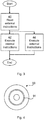
- Fig 3 is a flow chart illustrating embodiments of methods for controlling the energy storage system of Fig 1 , performed in the control device 1.
- external instructions 56 are read from the external removable memory via the external memory interface 50.
- control interface 53 In an execute internal instructions step 42, internal instructions 66 from the internal memory 64 are executed to thereby provide access to the control interface 53, for controlling the energy storage system 3, for the external instructions 56.
- the control interface 53 can comprise an interface to read parameters of the energy storage system 3 e.g. current configuration and/or measurements of voltage, current, frequency, power, temperature, etc., from any connected devices.
- the control interface 53 can comprise an interface to set a set point for the energy storage system 3, e.g. active power P and/or reactive power Q.
- this step comprises providing access to the user interface device 52 of the control device 1 for the external instructions 56, providing a way for the external instructions to interact with a user of the control device 1.
- this step comprises providing access to the network interface 62 for the external instructions 56, providing even more flexibility for the operator of the energy storage system.
- an execute external instructions step 44 the external instructions 56 are executed, which are then given access to the control interface 53 and optionally the user interface device 52 and/or the network interface 62.
- execute internal instructions step 42 and execute external instructions step 44 can be performed in parallel.
- the read external instructions step 40 can optionally form part of the execute external instructions step 44.
- Fig 4 shows one example of a computer program product comprising computer readable means.
- a computer program 91 can be stored, which computer program can cause a processor to execute a method according to embodiments described herein.
- the computer program product is an optical disc, such as a CD (compact disc) or a DVD (digital versatile disc) or a Blu-Ray disc.
- the computer program product could also be embodied in a memory of a device, such as the computer program product 64 of Fig 2 .
- the computer program 91 is here schematically shown as a track on the depicted optical disk, the computer program can be stored in any way which is suitable for the computer program product, such as a removable solid state memory, e.g. a Universal Serial Bus (USB) drive.
- USB Universal Serial Bus
Landscapes
- Engineering & Computer Science (AREA)
- Power Engineering (AREA)
- General Engineering & Computer Science (AREA)
- Physics & Mathematics (AREA)
- General Physics & Mathematics (AREA)
- Automation & Control Theory (AREA)
- Supply And Distribution Of Alternating Current (AREA)
- Charge And Discharge Circuits For Batteries Or The Like (AREA)
Claims (13)
- Steuervorrichtung (1) zum Steuern eines Energiespeichersystems (3), das eine Energiespeichervorrichtung (10), einen bidirektionalen AC/DC-Umrichter (11) und eine Netzverbindung (12) zu einem elektrischen Stromverteilungsnetz (13) umfasst, wobei die Steuervorrichtung (1) umfasst:einen Prozessor (60);eine externe Speicherschnittstelle (50) zum Lesen von externen Befehlen (56) von einer externen entfernbaren Schnittstellenvorrichtung (51);eine Steuerschnittstelle (53) zum Steuern eines Energiespeichersystems (3); undeinen internen Speicher (64) zum Speichern von internen Softwarebefehlen (66), die, wenn sie von dem Prozessor (60) ausgeführt werden, konfiguriert sind, um die Steuervorrichtung (1) zu veranlassen, einen Zugriff auf die Steuerschnittstelle (53) für externe Befehle (56) bereitzustellen, die aus der externen entfernbaren Schnittstellenvorrichtung (51) gelesen werden, wenn die externen Befehle (56) von dem Prozessor (60) ausgeführt werden;dadurch gekennzeichnet, dass die externen Befehle (56) Softwarebefehle sind.
- Steuervorrichtung (1) nach Anspruch 1, die außerdem eine Benutzeroberflächenvorrichtung (52) umfasst und wobei die internen Softwarebefehle (66) außerdem Befehle umfassen, die, wenn sie von dem Prozessor (60) ausgeführt werden, die Steuervorrichtung (1) veranlassen, einen Zugriff auf die Benutzeroberflächenvorrichtung (52) für die externen Befehle (56) bereitzustellen, die aus der externen entfernbaren Schnittstellenvorrichtung (51) gelesen werden, wenn die externen Softwarebefehle (56) von dem Prozessor (60) ausgeführt werden.
- Steuervorrichtung (1) nach Anspruch 2, wobei die internen Softwarebefehle (66) Befehle umfassen, die, wenn sie von dem Prozessor (60) ausgeführt werden, die Steuervorrichtung (1) veranlassen, einen Zugriff auf einen Teilbereich einer Bildschirmfläche der Benutzeroberflächenvorrichtung (52) für die externen Softwarebefehle (56) bereitzustellen.
- Steuervorrichtung (1) nach einem der Ansprüche 1 bis 3, die außerdem eine Netzwerkschnittstelle (62) umfasst und wobei die internen Softwarebefehle (66) außerdem Befehle umfassen, die, wenn sie von dem Prozessor (60) ausgeführt werden, die Steuervorrichtung (1) veranlassen einen Zugriff auf die Netzwerkschnittstelle (62) für die externen Befehle (56) bereitzustellen, die aus der externen entfernbaren Schnittstellenvorrichtung (51) gelesen werden, wenn die externen Softwarebefehle (56) von dem Prozessor (60) ausgeführt werden.
- Steuervorrichtung (1) nach einem der Ansprüche 1 bis 4, wobei die Steuerschnittstelle (53) eine Schnittstelle zum Lesen von zwei Parametern des Energiespeichersystems (3) umfasst.
- Steuervorrichtung (1) nach einem der Ansprüche 1 bis 5, wobei die Steuerschnittstelle (53) eine Schnittstelle zum Einstellen eines Sollwerts für das Energiespeichersystem (3) umfasst.
- Verfahren zum Steuern eines Energiespeichersystems (3), die eine Energiespeichervorrichtung (10), einen bidirektionalen AC/DC-Umrichter (11) und eine Netzverbindung (12) zu einem elektrischen Stromverteilungsnetz (13) umfasst, wobei das Verfahren in einer Steuervorrichtung (1) des Energiespeichersystems (3) ausgeführt wird und die folgenden Schritte umfasst:Lesen (40) von externen Softwarebefehlen (56) über eine externe Speicherschnittstelle (50) aus einem externen entfernbaren Speicher;Ausführen (42) von internen Softwarebefehlen (66) aus einem internen Speicher (64), um dadurch einen Zugriff auf eine Steuerschnittstelle (53) zum Steuern der Benutzeroberflächenvorrichtung (3) für die externen Softwarebefehle (56) bereitzustellen; undAusführen (44) der externen Softwarebefehle (56).
- Verfahren nach Anspruch 7, wobei der Schritt des Ausführens (42) außerdem ein Ausführen der internen Softwarebefehle (66) aus dem internen Speicher (64) umfasst, um dadurch einen Zugriff auf eine Benutzeroberflächenvorrichtung (52) für die externen Softwarebefehle (56) bereitzustellen.
- Verfahren nach Anspruch 7 oder 8, wobei der Schritt des Ausführens (42) außerdem ein Ausführen der internen Softwarebefehle (66) aus dem internen Speicher (64) umfasst, um dadurch einen Zugriff auf eine Netzwerkschnittstelle (62) für die externen Softwarebefehle (56) bereitzustellen.
- Verfahren nach einem der Ansprüche 7 bis 9, wobei die Steuerschnittstelle (53) eine Schnittstelle zum Lesen von zwei Parametern des Energiespeichersystems (3) umfasst.
- Verfahren nach einem der Ansprüche 7 bis 10, wobei die Steuerschnittstelle (53) eine Schnittstelle zum Einstellen eines Sollwerts für das Energiespeichersystem (3) umfasst.
- Computerprogramm (66, 91) zum Steuern eines Energiespeichersystems (3), das eine Energiespeichervorrichtung (10), einen bidirektionalen AC/DC-Umrichter (11) und eine Netzverbindung (12) zu einem elektrischen Stromverteilungsnetz (13) umfasst, wobei das Computerprogramm einen Computerprogrammcode umfasst, der, wenn er auf einer Steuervorrichtung (1) des Energiespeichersystems (3) abläuft, die Steuervorrichtung veranlasst zum:Lesen von externen Softwarebefehlen (56) über eine externe Speicherschnittstelle (50) aus einem externen entfernbaren Speicher;Ausführen von internen Softwarebefehlen (66) aus einem internen Speicher (64), um dadurch einen Zugriff auf eine Steuerschnittstelle (53) zum Steuern der Benutzeroberflächenvorrichtung (3) für die externen Softwarebefehle (56) bereitzustellen; undAusführen der externen Softwarebefehle (56).
- Computerprogrammprodukt (64, 90), das ein Computerprogramm nach Anspruch 12 und ein computerlesbares Element umfasst, in dem das Computerprogramm gespeichert ist.
Priority Applications (6)
| Application Number | Priority Date | Filing Date | Title |
|---|---|---|---|
| DK16191857.8T DK3301773T3 (da) | 2016-09-30 | 2016-09-30 | Styring af et energilagringssystem |
| EP16191857.8A EP3301773B1 (de) | 2016-09-30 | 2016-09-30 | Verwaltung eines energiespeichersystems |
| CN201780060109.6A CN109792151B (zh) | 2016-09-30 | 2017-09-25 | 控制能量存储系统 |
| PCT/EP2017/074201 WO2018060128A1 (en) | 2016-09-30 | 2017-09-25 | Controlling an energy storage system |
| US16/331,813 US12394985B2 (en) | 2016-09-30 | 2017-09-25 | Controlling an energy storage system |
| KR1020197007607A KR102083134B1 (ko) | 2016-09-30 | 2017-09-25 | 에너지 저장 시스템의 제어 |
Applications Claiming Priority (1)
| Application Number | Priority Date | Filing Date | Title |
|---|---|---|---|
| EP16191857.8A EP3301773B1 (de) | 2016-09-30 | 2016-09-30 | Verwaltung eines energiespeichersystems |
Publications (2)
| Publication Number | Publication Date |
|---|---|
| EP3301773A1 EP3301773A1 (de) | 2018-04-04 |
| EP3301773B1 true EP3301773B1 (de) | 2020-06-03 |
Family
ID=57240795
Family Applications (1)
| Application Number | Title | Priority Date | Filing Date |
|---|---|---|---|
| EP16191857.8A Active EP3301773B1 (de) | 2016-09-30 | 2016-09-30 | Verwaltung eines energiespeichersystems |
Country Status (6)
| Country | Link |
|---|---|
| US (1) | US12394985B2 (de) |
| EP (1) | EP3301773B1 (de) |
| KR (1) | KR102083134B1 (de) |
| CN (1) | CN109792151B (de) |
| DK (1) | DK3301773T3 (de) |
| WO (1) | WO2018060128A1 (de) |
Families Citing this family (2)
| Publication number | Priority date | Publication date | Assignee | Title |
|---|---|---|---|---|
| DE102019217516A1 (de) | 2019-11-13 | 2021-06-02 | Robert Bosch Gmbh | Steuerungssystem für eine Automationsanlage und Verfahren zum Betreiben einer Automationsanlage |
| CN116264396B (zh) * | 2021-12-15 | 2024-09-06 | 金风科技股份有限公司 | 风力发电机组、风电变流器的控制方法和控制装置 |
Family Cites Families (15)
| Publication number | Priority date | Publication date | Assignee | Title |
|---|---|---|---|---|
| JPH117315A (ja) | 1997-04-21 | 1999-01-12 | Toshiba Corp | 監視・制御システム及びその処理内容を記録した媒体 |
| US20030201990A1 (en) | 2002-04-16 | 2003-10-30 | Aldrich Bradley C. | Color adaptation for multimedia devices |
| AU2009244877B2 (en) | 2008-05-09 | 2012-07-19 | Accenture Global Services Limited | Method and system for managing a power grid |
| EP2293406B1 (de) | 2009-09-07 | 2015-08-05 | ABB Research Ltd. | Energiespeichersysteme |
| US8754547B2 (en) * | 2010-11-17 | 2014-06-17 | Battelle Memorial Institute | Controller for hybrid energy storage |
| WO2013019989A2 (en) | 2011-08-02 | 2013-02-07 | The Regents Of The University Of California | Intelligent electric vehicle charging system |
| US9313655B2 (en) | 2011-10-31 | 2016-04-12 | Nokia Corporation | Location privacy in communication networks |
| US9270118B2 (en) * | 2012-07-19 | 2016-02-23 | Solarcity Corporation | Techniques for controlling energy generation and storage systems |
| EP2688173B1 (de) | 2012-07-20 | 2017-03-22 | Panasonic Intellectual Property Management Co., Ltd. | Mehrfachsystembereitstellung mit Energiespeichersystem |
| US8924608B2 (en) * | 2013-06-25 | 2014-12-30 | Airwatch Llc | Peripheral device management |
| CN107111352A (zh) * | 2014-11-04 | 2017-08-29 | Lo3能源有限公司 | 计算生成的热能的使用 |
| JP6204614B2 (ja) * | 2014-11-27 | 2017-09-27 | 京セラ株式会社 | 電力制御装置、電力制御方法及び電力制御システム |
| US20160179062A1 (en) * | 2014-12-17 | 2016-06-23 | Caterpillar Inc. | Machine data management system using removable controller |
| US10319408B2 (en) * | 2015-03-30 | 2019-06-11 | Manufacturing Resources International, Inc. | Monolithic display with separately controllable sections |
| DE102015116656A1 (de) * | 2015-10-01 | 2017-04-06 | Océ Printing Systems GmbH & Co. KG | Verfahren zum Reduzieren einer lokal erhöhten Viskosität von Tinte in einem Tintendruckkopf eines Tintendruckers während des Druckbetriebs |
-
2016
- 2016-09-30 EP EP16191857.8A patent/EP3301773B1/de active Active
- 2016-09-30 DK DK16191857.8T patent/DK3301773T3/da active
-
2017
- 2017-09-25 CN CN201780060109.6A patent/CN109792151B/zh active Active
- 2017-09-25 US US16/331,813 patent/US12394985B2/en active Active
- 2017-09-25 WO PCT/EP2017/074201 patent/WO2018060128A1/en not_active Ceased
- 2017-09-25 KR KR1020197007607A patent/KR102083134B1/ko active Active
Non-Patent Citations (1)
| Title |
|---|
| None * |
Also Published As
| Publication number | Publication date |
|---|---|
| WO2018060128A1 (en) | 2018-04-05 |
| US20190341799A1 (en) | 2019-11-07 |
| EP3301773A1 (de) | 2018-04-04 |
| CN109792151B (zh) | 2021-02-26 |
| DK3301773T3 (da) | 2020-09-07 |
| KR102083134B1 (ko) | 2020-02-28 |
| US12394985B2 (en) | 2025-08-19 |
| CN109792151A (zh) | 2019-05-21 |
| KR20190035911A (ko) | 2019-04-03 |
Similar Documents
| Publication | Publication Date | Title |
|---|---|---|
| JP2011507464A (ja) | 電源を電力システムに接続する装置および方法 | |
| Chen et al. | Electricity demand and grid impacts of AI data centers: Challenges and prospects | |
| CN106030452B (zh) | 计算系统的备用电源管理 | |
| JP6135763B2 (ja) | 充電電力制御方法、充電電力制御システムおよびプログラム | |
| US20120277926A1 (en) | Transformer structure for smart load balancing | |
| Nutkani et al. | Power flow control of intertied ac microgrids | |
| CN109066745B (zh) | 电储能系统及其运行控制方法、装置、系统 | |
| JP2013005718A (ja) | 配電システムを動作させるためのシステム、方法、および装置 | |
| US20210296900A1 (en) | Datacenter power management through phase balancing | |
| US9778068B2 (en) | Systems and methods for conditioning and controlling power usage | |
| Liang et al. | Design guidelines for MPC‐based frequency regulation for islanded microgrids with storage, voltage, and ramping constraints | |
| JP2019193317A (ja) | 蓄電システム、充放電制御装置、その制御方法、およびプログラム | |
| EP3301773B1 (de) | Verwaltung eines energiespeichersystems | |
| Yin et al. | Hierarchical control system for a flexible microgrid with dynamic boundary: design, implementation and testing | |
| CN119493458A (zh) | 在机柜系统的电源管理方法和相关网络数据中心 | |
| JP5415654B1 (ja) | 配線切替えシステム | |
| JP6783630B2 (ja) | 機器制御装置、機器制御方法、およびプログラム | |
| US20220100250A1 (en) | Datacenter power management with edge mediation block | |
| JP6454929B2 (ja) | 蓄電池制御システム、蓄電池制御方法、およびプログラム | |
| Nguyen et al. | Three‐wire network: a new distribution system approach considering both distributed generation and load requirements | |
| Starke et al. | A 1kV, 480V Power Electronics Hub for DER Integration in Commercial Buildings | |
| JP2018064430A (ja) | 充放電装置及び電力制御装置 | |
| Hu et al. | Two‐stage EMS for distribution network under defensive islanding | |
| CN118655947B (zh) | 一种可编程直流电源输出控制方法、装置、设备及介质 | |
| WO2014157663A1 (ja) | 電力管理装置、電力管理方法及びプログラム |
Legal Events
| Date | Code | Title | Description |
|---|---|---|---|
| PUAI | Public reference made under article 153(3) epc to a published international application that has entered the european phase |
Free format text: ORIGINAL CODE: 0009012 |
|
| STAA | Information on the status of an ep patent application or granted ep patent |
Free format text: STATUS: THE APPLICATION HAS BEEN PUBLISHED |
|
| AK | Designated contracting states |
Kind code of ref document: A1 Designated state(s): AL AT BE BG CH CY CZ DE DK EE ES FI FR GB GR HR HU IE IS IT LI LT LU LV MC MK MT NL NO PL PT RO RS SE SI SK SM TR |
|
| AX | Request for extension of the european patent |
Extension state: BA ME |
|
| STAA | Information on the status of an ep patent application or granted ep patent |
Free format text: STATUS: REQUEST FOR EXAMINATION WAS MADE |
|
| 17P | Request for examination filed |
Effective date: 20181004 |
|
| RBV | Designated contracting states (corrected) |
Designated state(s): AL AT BE BG CH CY CZ DE DK EE ES FI FR GB GR HR HU IE IS IT LI LT LU LV MC MK MT NL NO PL PT RO RS SE SI SK SM TR |
|
| STAA | Information on the status of an ep patent application or granted ep patent |
Free format text: STATUS: EXAMINATION IS IN PROGRESS |
|
| 17Q | First examination report despatched |
Effective date: 20190328 |
|
| GRAP | Despatch of communication of intention to grant a patent |
Free format text: ORIGINAL CODE: EPIDOSNIGR1 |
|
| STAA | Information on the status of an ep patent application or granted ep patent |
Free format text: STATUS: GRANT OF PATENT IS INTENDED |
|
| INTG | Intention to grant announced |
Effective date: 20200107 |
|
| GRAS | Grant fee paid |
Free format text: ORIGINAL CODE: EPIDOSNIGR3 |
|
| GRAA | (expected) grant |
Free format text: ORIGINAL CODE: 0009210 |
|
| STAA | Information on the status of an ep patent application or granted ep patent |
Free format text: STATUS: THE PATENT HAS BEEN GRANTED |
|
| AK | Designated contracting states |
Kind code of ref document: B1 Designated state(s): AL AT BE BG CH CY CZ DE DK EE ES FI FR GB GR HR HU IE IS IT LI LT LU LV MC MK MT NL NO PL PT RO RS SE SI SK SM TR |
|
| RAP1 | Party data changed (applicant data changed or rights of an application transferred) |
Owner name: ABB SCHWEIZ AG |
|
| REG | Reference to a national code |
Ref country code: GB Ref legal event code: FG4D |
|
| REG | Reference to a national code |
Ref country code: CH Ref legal event code: EP Ref country code: AT Ref legal event code: REF Ref document number: 1278020 Country of ref document: AT Kind code of ref document: T Effective date: 20200615 |
|
| REG | Reference to a national code |
Ref country code: DE Ref legal event code: R096 Ref document number: 602016037390 Country of ref document: DE |
|
| REG | Reference to a national code |
Ref country code: DK Ref legal event code: T3 Effective date: 20200903 |
|
| REG | Reference to a national code |
Ref country code: LT Ref legal event code: MG4D |
|
| PG25 | Lapsed in a contracting state [announced via postgrant information from national office to epo] |
Ref country code: SE Free format text: LAPSE BECAUSE OF FAILURE TO SUBMIT A TRANSLATION OF THE DESCRIPTION OR TO PAY THE FEE WITHIN THE PRESCRIBED TIME-LIMIT Effective date: 20200603 Ref country code: GR Free format text: LAPSE BECAUSE OF FAILURE TO SUBMIT A TRANSLATION OF THE DESCRIPTION OR TO PAY THE FEE WITHIN THE PRESCRIBED TIME-LIMIT Effective date: 20200904 Ref country code: LT Free format text: LAPSE BECAUSE OF FAILURE TO SUBMIT A TRANSLATION OF THE DESCRIPTION OR TO PAY THE FEE WITHIN THE PRESCRIBED TIME-LIMIT Effective date: 20200603 Ref country code: NO Free format text: LAPSE BECAUSE OF FAILURE TO SUBMIT A TRANSLATION OF THE DESCRIPTION OR TO PAY THE FEE WITHIN THE PRESCRIBED TIME-LIMIT Effective date: 20200903 Ref country code: FI Free format text: LAPSE BECAUSE OF FAILURE TO SUBMIT A TRANSLATION OF THE DESCRIPTION OR TO PAY THE FEE WITHIN THE PRESCRIBED TIME-LIMIT Effective date: 20200603 |
|
| REG | Reference to a national code |
Ref country code: NL Ref legal event code: MP Effective date: 20200603 |
|
| PG25 | Lapsed in a contracting state [announced via postgrant information from national office to epo] |
Ref country code: LV Free format text: LAPSE BECAUSE OF FAILURE TO SUBMIT A TRANSLATION OF THE DESCRIPTION OR TO PAY THE FEE WITHIN THE PRESCRIBED TIME-LIMIT Effective date: 20200603 Ref country code: HR Free format text: LAPSE BECAUSE OF FAILURE TO SUBMIT A TRANSLATION OF THE DESCRIPTION OR TO PAY THE FEE WITHIN THE PRESCRIBED TIME-LIMIT Effective date: 20200603 Ref country code: BG Free format text: LAPSE BECAUSE OF FAILURE TO SUBMIT A TRANSLATION OF THE DESCRIPTION OR TO PAY THE FEE WITHIN THE PRESCRIBED TIME-LIMIT Effective date: 20200903 Ref country code: RS Free format text: LAPSE BECAUSE OF FAILURE TO SUBMIT A TRANSLATION OF THE DESCRIPTION OR TO PAY THE FEE WITHIN THE PRESCRIBED TIME-LIMIT Effective date: 20200603 |
|
| REG | Reference to a national code |
Ref country code: AT Ref legal event code: MK05 Ref document number: 1278020 Country of ref document: AT Kind code of ref document: T Effective date: 20200603 |
|
| PG25 | Lapsed in a contracting state [announced via postgrant information from national office to epo] |
Ref country code: AL Free format text: LAPSE BECAUSE OF FAILURE TO SUBMIT A TRANSLATION OF THE DESCRIPTION OR TO PAY THE FEE WITHIN THE PRESCRIBED TIME-LIMIT Effective date: 20200603 Ref country code: NL Free format text: LAPSE BECAUSE OF FAILURE TO SUBMIT A TRANSLATION OF THE DESCRIPTION OR TO PAY THE FEE WITHIN THE PRESCRIBED TIME-LIMIT Effective date: 20200603 |
|
| PG25 | Lapsed in a contracting state [announced via postgrant information from national office to epo] |
Ref country code: CZ Free format text: LAPSE BECAUSE OF FAILURE TO SUBMIT A TRANSLATION OF THE DESCRIPTION OR TO PAY THE FEE WITHIN THE PRESCRIBED TIME-LIMIT Effective date: 20200603 Ref country code: PT Free format text: LAPSE BECAUSE OF FAILURE TO SUBMIT A TRANSLATION OF THE DESCRIPTION OR TO PAY THE FEE WITHIN THE PRESCRIBED TIME-LIMIT Effective date: 20201006 Ref country code: RO Free format text: LAPSE BECAUSE OF FAILURE TO SUBMIT A TRANSLATION OF THE DESCRIPTION OR TO PAY THE FEE WITHIN THE PRESCRIBED TIME-LIMIT Effective date: 20200603 Ref country code: ES Free format text: LAPSE BECAUSE OF FAILURE TO SUBMIT A TRANSLATION OF THE DESCRIPTION OR TO PAY THE FEE WITHIN THE PRESCRIBED TIME-LIMIT Effective date: 20200603 Ref country code: AT Free format text: LAPSE BECAUSE OF FAILURE TO SUBMIT A TRANSLATION OF THE DESCRIPTION OR TO PAY THE FEE WITHIN THE PRESCRIBED TIME-LIMIT Effective date: 20200603 Ref country code: EE Free format text: LAPSE BECAUSE OF FAILURE TO SUBMIT A TRANSLATION OF THE DESCRIPTION OR TO PAY THE FEE WITHIN THE PRESCRIBED TIME-LIMIT Effective date: 20200603 Ref country code: SM Free format text: LAPSE BECAUSE OF FAILURE TO SUBMIT A TRANSLATION OF THE DESCRIPTION OR TO PAY THE FEE WITHIN THE PRESCRIBED TIME-LIMIT Effective date: 20200603 |
|
| PG25 | Lapsed in a contracting state [announced via postgrant information from national office to epo] |
Ref country code: SK Free format text: LAPSE BECAUSE OF FAILURE TO SUBMIT A TRANSLATION OF THE DESCRIPTION OR TO PAY THE FEE WITHIN THE PRESCRIBED TIME-LIMIT Effective date: 20200603 Ref country code: PL Free format text: LAPSE BECAUSE OF FAILURE TO SUBMIT A TRANSLATION OF THE DESCRIPTION OR TO PAY THE FEE WITHIN THE PRESCRIBED TIME-LIMIT Effective date: 20200603 Ref country code: IS Free format text: LAPSE BECAUSE OF FAILURE TO SUBMIT A TRANSLATION OF THE DESCRIPTION OR TO PAY THE FEE WITHIN THE PRESCRIBED TIME-LIMIT Effective date: 20201003 |
|
| REG | Reference to a national code |
Ref country code: DE Ref legal event code: R097 Ref document number: 602016037390 Country of ref document: DE |
|
| RAP2 | Party data changed (patent owner data changed or rights of a patent transferred) |
Owner name: ABB POWER GRIDS SWITZERLAND AG |
|
| PLBE | No opposition filed within time limit |
Free format text: ORIGINAL CODE: 0009261 |
|
| STAA | Information on the status of an ep patent application or granted ep patent |
Free format text: STATUS: NO OPPOSITION FILED WITHIN TIME LIMIT |
|
| REG | Reference to a national code |
Ref country code: CH Ref legal event code: PL |
|
| 26N | No opposition filed |
Effective date: 20210304 |
|
| REG | Reference to a national code |
Ref country code: DE Ref legal event code: R081 Ref document number: 602016037390 Country of ref document: DE Owner name: HITACHI ENERGY SWITZERLAND AG, CH Free format text: FORMER OWNER: ABB SCHWEIZ AG, BADEN, CH Ref country code: DE Ref legal event code: R081 Ref document number: 602016037390 Country of ref document: DE Owner name: HITACHI ENERGY LTD, CH Free format text: FORMER OWNER: ABB SCHWEIZ AG, BADEN, CH Ref country code: DE Ref legal event code: R081 Ref document number: 602016037390 Country of ref document: DE Owner name: ABB POWER GRIDS SWITZERLAND AG, CH Free format text: FORMER OWNER: ABB SCHWEIZ AG, BADEN, CH |
|
| PG25 | Lapsed in a contracting state [announced via postgrant information from national office to epo] |
Ref country code: SI Free format text: LAPSE BECAUSE OF FAILURE TO SUBMIT A TRANSLATION OF THE DESCRIPTION OR TO PAY THE FEE WITHIN THE PRESCRIBED TIME-LIMIT Effective date: 20200603 |
|
| REG | Reference to a national code |
Ref country code: BE Ref legal event code: MM Effective date: 20200930 |
|
| PG25 | Lapsed in a contracting state [announced via postgrant information from national office to epo] |
Ref country code: LU Free format text: LAPSE BECAUSE OF NON-PAYMENT OF DUE FEES Effective date: 20200930 |
|
| PG25 | Lapsed in a contracting state [announced via postgrant information from national office to epo] |
Ref country code: IE Free format text: LAPSE BECAUSE OF NON-PAYMENT OF DUE FEES Effective date: 20200930 Ref country code: LI Free format text: LAPSE BECAUSE OF NON-PAYMENT OF DUE FEES Effective date: 20200930 Ref country code: BE Free format text: LAPSE BECAUSE OF NON-PAYMENT OF DUE FEES Effective date: 20200930 Ref country code: CH Free format text: LAPSE BECAUSE OF NON-PAYMENT OF DUE FEES Effective date: 20200930 |
|
| REG | Reference to a national code |
Ref country code: GB Ref legal event code: 732E Free format text: REGISTERED BETWEEN 20211104 AND 20211110 |
|
| PG25 | Lapsed in a contracting state [announced via postgrant information from national office to epo] |
Ref country code: TR Free format text: LAPSE BECAUSE OF FAILURE TO SUBMIT A TRANSLATION OF THE DESCRIPTION OR TO PAY THE FEE WITHIN THE PRESCRIBED TIME-LIMIT Effective date: 20200603 Ref country code: MT Free format text: LAPSE BECAUSE OF FAILURE TO SUBMIT A TRANSLATION OF THE DESCRIPTION OR TO PAY THE FEE WITHIN THE PRESCRIBED TIME-LIMIT Effective date: 20200603 Ref country code: CY Free format text: LAPSE BECAUSE OF FAILURE TO SUBMIT A TRANSLATION OF THE DESCRIPTION OR TO PAY THE FEE WITHIN THE PRESCRIBED TIME-LIMIT Effective date: 20200603 |
|
| REG | Reference to a national code |
Ref country code: DE Ref legal event code: R081 Ref document number: 602016037390 Country of ref document: DE Owner name: HITACHI ENERGY SWITZERLAND AG, CH Free format text: FORMER OWNER: ABB POWER GRIDS SWITZERLAND AG, BADEN, CH Ref country code: DE Ref legal event code: R081 Ref document number: 602016037390 Country of ref document: DE Owner name: HITACHI ENERGY LTD, CH Free format text: FORMER OWNER: ABB POWER GRIDS SWITZERLAND AG, BADEN, CH |
|
| PG25 | Lapsed in a contracting state [announced via postgrant information from national office to epo] |
Ref country code: MK Free format text: LAPSE BECAUSE OF FAILURE TO SUBMIT A TRANSLATION OF THE DESCRIPTION OR TO PAY THE FEE WITHIN THE PRESCRIBED TIME-LIMIT Effective date: 20200603 Ref country code: MC Free format text: LAPSE BECAUSE OF FAILURE TO SUBMIT A TRANSLATION OF THE DESCRIPTION OR TO PAY THE FEE WITHIN THE PRESCRIBED TIME-LIMIT Effective date: 20200603 |
|
| P01 | Opt-out of the competence of the unified patent court (upc) registered |
Effective date: 20230527 |
|
| REG | Reference to a national code |
Ref country code: DE Ref legal event code: R082 Ref document number: 602016037390 Country of ref document: DE Representative=s name: DENNEMEYER & ASSOCIATES RECHTSANWALTSGESELLSCH, DE Ref country code: DE Ref legal event code: R082 Ref document number: 602016037390 Country of ref document: DE Representative=s name: DENNEMEYER & ASSOCIATES S.A., DE Ref country code: DE Ref legal event code: R081 Ref document number: 602016037390 Country of ref document: DE Owner name: HITACHI ENERGY LTD, CH Free format text: FORMER OWNER: HITACHI ENERGY SWITZERLAND AG, BADEN, CH |
|
| REG | Reference to a national code |
Ref country code: GB Ref legal event code: 732E Free format text: REGISTERED BETWEEN 20240718 AND 20240724 |
|
| REG | Reference to a national code |
Ref country code: DE Ref legal event code: R082 Ref document number: 602016037390 Country of ref document: DE Representative=s name: DENNEMEYER & ASSOCIATES RECHTSANWALTSGESELLSCH, DE |
|
| PGFP | Annual fee paid to national office [announced via postgrant information from national office to epo] |
Ref country code: DK Payment date: 20250923 Year of fee payment: 10 Ref country code: DE Payment date: 20250919 Year of fee payment: 10 |
|
| PGFP | Annual fee paid to national office [announced via postgrant information from national office to epo] |
Ref country code: IT Payment date: 20250923 Year of fee payment: 10 |
|
| PGFP | Annual fee paid to national office [announced via postgrant information from national office to epo] |
Ref country code: GB Payment date: 20250919 Year of fee payment: 10 |
|
| PGFP | Annual fee paid to national office [announced via postgrant information from national office to epo] |
Ref country code: FR Payment date: 20250922 Year of fee payment: 10 |