EP3301361B1 - Pilot-/haupttreibstoffwechsel in einer axialstufenbrennkammer für einen gasturbinenmotor - Google Patents
Pilot-/haupttreibstoffwechsel in einer axialstufenbrennkammer für einen gasturbinenmotor Download PDFInfo
- Publication number
- EP3301361B1 EP3301361B1 EP17193551.3A EP17193551A EP3301361B1 EP 3301361 B1 EP3301361 B1 EP 3301361B1 EP 17193551 A EP17193551 A EP 17193551A EP 3301361 B1 EP3301361 B1 EP 3301361B1
- Authority
- EP
- European Patent Office
- Prior art keywords
- fuel
- combustor
- injection system
- fuel injection
- percentage
- Prior art date
- Legal status (The legal status is an assumption and is not a legal conclusion. Google has not performed a legal analysis and makes no representation as to the accuracy of the status listed.)
- Active
Links
Images


Classifications
-
- F—MECHANICAL ENGINEERING; LIGHTING; HEATING; WEAPONS; BLASTING
- F02—COMBUSTION ENGINES; HOT-GAS OR COMBUSTION-PRODUCT ENGINE PLANTS
- F02C—GAS-TURBINE PLANTS; AIR INTAKES FOR JET-PROPULSION PLANTS; CONTROLLING FUEL SUPPLY IN AIR-BREATHING JET-PROPULSION PLANTS
- F02C7/00—Features, components parts, details or accessories, not provided for in, or of interest apart form groups F02C1/00 - F02C6/00; Air intakes for jet-propulsion plants
- F02C7/22—Fuel supply systems
- F02C7/228—Dividing fuel between various burners
-
- F—MECHANICAL ENGINEERING; LIGHTING; HEATING; WEAPONS; BLASTING
- F23—COMBUSTION APPARATUS; COMBUSTION PROCESSES
- F23N—REGULATING OR CONTROLLING COMBUSTION
- F23N1/00—Regulating fuel supply
- F23N1/002—Regulating fuel supply using electronic means
-
- F—MECHANICAL ENGINEERING; LIGHTING; HEATING; WEAPONS; BLASTING
- F23—COMBUSTION APPARATUS; COMBUSTION PROCESSES
- F23N—REGULATING OR CONTROLLING COMBUSTION
- F23N5/00—Systems for controlling combustion
- F23N5/003—Systems for controlling combustion using detectors sensitive to combustion gas properties
-
- F—MECHANICAL ENGINEERING; LIGHTING; HEATING; WEAPONS; BLASTING
- F23—COMBUSTION APPARATUS; COMBUSTION PROCESSES
- F23N—REGULATING OR CONTROLLING COMBUSTION
- F23N5/00—Systems for controlling combustion
- F23N5/16—Systems for controlling combustion using noise-sensitive detectors
-
- F—MECHANICAL ENGINEERING; LIGHTING; HEATING; WEAPONS; BLASTING
- F23—COMBUSTION APPARATUS; COMBUSTION PROCESSES
- F23R—GENERATING COMBUSTION PRODUCTS OF HIGH PRESSURE OR HIGH VELOCITY, e.g. GAS-TURBINE COMBUSTION CHAMBERS
- F23R3/00—Continuous combustion chambers using liquid or gaseous fuel
- F23R3/28—Continuous combustion chambers using liquid or gaseous fuel characterised by the fuel supply
- F23R3/34—Feeding into different combustion zones
- F23R3/343—Pilot flames, i.e. fuel nozzles or injectors using only a very small proportion of the total fuel to insure continuous combustion
-
- F—MECHANICAL ENGINEERING; LIGHTING; HEATING; WEAPONS; BLASTING
- F23—COMBUSTION APPARATUS; COMBUSTION PROCESSES
- F23R—GENERATING COMBUSTION PRODUCTS OF HIGH PRESSURE OR HIGH VELOCITY, e.g. GAS-TURBINE COMBUSTION CHAMBERS
- F23R3/00—Continuous combustion chambers using liquid or gaseous fuel
- F23R3/28—Continuous combustion chambers using liquid or gaseous fuel characterised by the fuel supply
- F23R3/34—Feeding into different combustion zones
- F23R3/346—Feeding into different combustion zones for staged combustion
-
- Y—GENERAL TAGGING OF NEW TECHNOLOGICAL DEVELOPMENTS; GENERAL TAGGING OF CROSS-SECTIONAL TECHNOLOGIES SPANNING OVER SEVERAL SECTIONS OF THE IPC; TECHNICAL SUBJECTS COVERED BY FORMER USPC CROSS-REFERENCE ART COLLECTIONS [XRACs] AND DIGESTS
- Y02—TECHNOLOGIES OR APPLICATIONS FOR MITIGATION OR ADAPTATION AGAINST CLIMATE CHANGE
- Y02T—CLIMATE CHANGE MITIGATION TECHNOLOGIES RELATED TO TRANSPORTATION
- Y02T50/00—Aeronautics or air transport
- Y02T50/60—Efficient propulsion technologies, e.g. for aircraft
Definitions
- the present disclosure relates to a gas turbine engine and, more particularly, to a combustor section therefor.
- Gas turbine engines such as those which power modern commercial and military aircrafts, include a compressor for pressurizing a supply of air, a combustor for burning a hydrocarbon fuel in the presence of the pressurized air, and a turbine for extracting energy from the resultant combustion gases.
- the combustor generally includes radially spaced apart inner and outer liners that define an annular combustion chamber therebetween. Arrays of circumferentially distributed combustion air holes penetrate multiple axial locations along each liner to radially admit the pressurized air into the combustion chamber. A plurality of circumferentially distributed fuel injectors axially project into a forward section of the combustion chamber to supply the fuel for mixing with the pressurized air.
- NOX nitrogen oxide
- Lean-staged liquid-fueled aeroengine combustors can provide low NOx and particulate matter emissions, but are also prone to combustion instabilities. There are several mechanism that may cause combustion instabilities in radial-staged lean combustors including heat release concentrated in the front of the combustor, and weak flame holding at certain operating conditions where main stage air dilutes the pilot stage fuel-air ratio.
- Prior art includes US 2016/123596 A1 which covers the features specified in the preamble of claim 1, WO 2015/061217 A1 , US 2016/245525 A1 and US 2006/130455 A1 .
- a method of controlling a pilot/main fuel schedule to a combustor of a gas turbine engine according to one aspect of the present invention is claimed in claim 1.
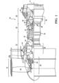
- FIG. 1 schematically illustrates a gas turbine engine 20.
- the gas turbine engine 20 is disclosed herein as a two-spool turbo fan that generally incorporates a fan section 22, a compressor section 24, a combustor section 26 and a turbine section 28.
- the fan section 22 drives air along a bypass flowpath while the compressor section 24 drives air along a core flowpath for compression and communication into the combustor section 26 then expansion through the turbine section 28.
- turbofan in the disclosed non-limiting embodiment, it should be understood that the concepts described herein are not limited to use with turbofans as the teachings may be applied to other types of turbine engines such as a turbojets, turboshafts, and three-spool (plus fan) turbofans wherein an intermediate spool includes an intermediate pressure compressor ("IPC") between a Low Pressure Compressor (“LPC”) and a High Pressure Compressor (“HPC”), and an intermediate pressure turbine (“IPT”) between the high pressure turbine (“HPT”) and the Low pressure Turbine (“LPT”).
- IPC intermediate pressure compressor
- LPC Low Pressure Compressor
- HPC High Pressure Compressor
- IPT intermediate pressure turbine
- the engine 20 generally includes a low spool 30 and a high spool 32 mounted for rotation about an engine central longitudinal axis A relative to an engine static structure 36 via several bearing structures 38.
- the low spool 30 generally includes an inner shaft 40 that interconnects a fan 42, a low pressure compressor (“LPC”) 44 and a low pressure turbine (“LPT”) 46.
- the inner shaft 40 drives the fan 42 directly or through a geared architecture 48 to drive the fan 42 at a lower speed than the low spool 30.
- An exemplary reduction transmission is an epicyclic transmission, namely a planetary or star gear system.
- the high spool 32 includes an outer shaft 50 that interconnects a high pressure compressor (“HPC”) 52 and high pressure turbine (“HPT”) 54.
- a combustor 56 is arranged between the high pressure compressor 52 and the high pressure turbine 54.
- the inner shaft 40 and the outer shaft 50 are concentric and rotate about the engine central longitudinal axis A which is collinear with their longitudinal axes.
- the main engine shafts 40, 50 are supported at a plurality of points by bearing structures 38 within the static structure 36. It should be understood that various bearing structures 38 at various locations may alternatively or additionally be provided.
- the gas turbine engine 20 is a high-bypass geared aircraft engine.
- the gas turbine engine 20 bypass ratio is greater than about six (6:1).
- the geared architecture 48 can include an epicyclic gear train, such as a planetary gear system or other gear system.
- the example epicyclic gear train has a gear reduction ratio of greater than about 2.3, and in another example is greater than about 2.5:1.
- the geared turbofan enables operation of the low spool 30 at higher speeds which can increase the operational efficiency of the LPC 44 and LPT 46 and render increased pressure in a fewer number of stages.
- a pressure ratio associated with the LPT 46 is pressure measured prior to the inlet of the LPT 46 as related to the pressure at the outlet of the LPT 46 prior to an exhaust nozzle of the gas turbine engine 20.
- the bypass ratio of the gas turbine engine 20 is greater than about ten (10:1)
- the fan diameter is significantly larger than that of the LPC 44
- the LPT 46 has a pressure ratio that is greater than about five (5:1). It should be understood, however, that the above parameters are only exemplary of one embodiment of a geared architecture engine and that the present disclosure is applicable to other gas turbine engines including direct drive turbofans.
- a significant amount of thrust is provided by the bypass flow path due to the high bypass ratio.
- the fan section 22 of the gas turbine engine 20 is designed for a particular flight condition - typically cruise at about 0.8 Mach and about 35,000 feet (10668 m). This flight condition, with the gas turbine engine 20 at its best fuel consumption, is also known as bucket cruise Thrust Specific Fuel Consumption (TSFC).
- TSFC Thrust Specific Fuel Consumption
- the Fan Pressure Ratio is the pressure ratio across a blade of the fan section 22 without the use of a Fan Exit Guide Vane system.
- the low Fan Pressure Ratio according to one non-limiting embodiment of the example gas turbine engine 20 is less than 1.45.
- Low Corrected Fan Tip Speed is the actual fan tip speed divided by an industry standard temperature correction of ("Tram" / 518.7) 0.5 .
- the Low Corrected Fan Tip Speed according to one non-limiting embodiment of the example gas turbine engine 20 is less than about 1150 fps (351 m/s).
- the combustor section 26 generally includes a combustor 56 with an outer combustor liner assembly 60, an inner combustor liner assembly 62 and a diffuser case module 64.
- the outer combustor liner assembly 60 and the inner combustor liner assembly 62 are spaced apart such that a combustion chamber 66 is defined therebetween.
- the combustion chamber 66 is generally annular in shape.
- the outer combustor liner assembly 60 is spaced radially inward from an outer diffuser case 64-O of the diffuser case module 64 to define an outer annular plenum 76.
- the inner combustor liner assembly 62 is spaced radially outward from an inner diffuser case 64-I of the diffuser case module 64 to define an inner annular plenum 78. It should be understood that although a particular combustor is illustrated, other combustor types with various combustor liner arrangements will also benefit herefrom. It should be further understood that the disclosed cooling flow paths are but an illustrated embodiment and should not be limited only thereto.
- the combustor liner assemblies 60, 62 contain the combustion products for direction toward the turbine section 28.
- Each combustor liner assembly 60, 62 generally includes a respective support shell 68, 70 which supports one or more liner panels 72, 74 mounted to a hot side of the respective support shell 68, 70.
- Each of the liner panels 72, 74 may be generally rectilinear and manufactured of, for example, a nickel based super alloy, ceramic or other temperature resistant material and are arranged to form a liner array.
- the liner array includes a multiple of forward liner panels 72A and a multiple of aft liner panels 72B that are circumferentially staggered to line the hot side of the outer shell 68 (also shown in Figure 3 ).
- a multiple of forward liner panels 74A and a multiple of aft liner panels 74B are circumferentially staggered to line the hot side of the inner shell 70 (also shown in Figure 3 ).
- the combustor 56 further includes a forward assembly 80 immediately downstream of the compressor section 24 to receive compressed airflow therefrom.
- the forward assembly 80 generally includes an annular hood 82, a bulkhead assembly 84, a multiple of forward fuel nozzles 86 (one shown) and a multiple of swirlers 90 (one shown).
- the multiple of fuel nozzles 86 (one shown) and the multiple of swirlers 90 (one shown) define an axial pilot fuel injection system 92 that directs the fuel-air mixture into the combustor chamber generally along an axis F.
- the bulkhead assembly 84 includes a bulkhead support shell 96 secured to the combustor liner assemblies 60, 62, and a multiple of circumferentially distributed bulkhead liner panels 98 secured to the bulkhead support shell 96.
- the annular hood 82 extends radially between, and is secured to, the forwardmost ends of the combustor liner assemblies 60, 62.
- the annular hood 82 includes a multiple of circumferentially distributed hood ports 94 that accommodate the respective forward fuel nozzles 86 and direct air into the forward end of the combustion chamber 66 through a respective swirler 90.
- Each forward fuel nozzle 86 may be secured to the diffuser case module 64 and project through one of the hood ports 94 and through the respective swirler 90.
- Each of the fuel nozzles 86 is directed through the respective swirler 90 and the bulkhead assembly 84 along a respective axis F.
- the forward assembly 80 introduces core combustion air into the forward section of the combustion chamber 66 while the remainder enters the outer annular plenum 76 and the inner annular plenum 78.
- the multiple of fuel nozzles 86 and adjacent structure generate a blended fuel-air mixture that supports stable combustion in the combustion chamber 66.
- the outer and inner support shells 68, 70 are mounted to a first row of Nozzle Guide Vanes (NGVs) 54A in the HPT 54 to define a combustor exit 100.
- NGVs 54A are static engine components which direct core airflow combustion gases onto the turbine blades of the first turbine rotor in the turbine section 28 to facilitate the conversion of pressure energy into kinetic energy.
- the combustion gases are also accelerated by the NGVs 54A because of their convergent shape and are typically given a "spin” or a "swirl” in the direction of turbine rotor rotation.
- the turbine rotor blades absorb this energy to drive the turbine rotor at high speed.
- a multiple of cooling impingement holes 104 penetrate through the support shells 68, 70 to allow air from the respective annular plenums 76, 78 to enter cavities 106A, 106B formed in the combustor liner assemblies 60, 62 between the respective support shells 68, 70 and liner panels 72, 74.
- the cooling impingement holes 104 are generally normal to the surface of the liner panels 72, 74.
- the air in the cavities 106A, 106B provides cold side impingement cooling of the liner panels 72, 74 that is generally defined herein as heat removal via internal convection.
- the geometry of the film holes, e.g, diameter, shape, density, surface angle, incidence angle, etc., as well as the location of the holes with respect to the high temperature main flow also contributes to effusion film cooling.
- the liner panels 72, 74 with a combination of impingement holes 104 and film holes 108 may sometimes be referred to as an Impingement Film Floatliner assembly. It should be appreciated that other liner panel assemblies inclusive of a single panel.
- the cooling film holes 108 allow the air to pass from the cavities 106A, 106B defined in part by a cold side 110 of the liner panels 72, 74 to a hot side 112 of the liner panels 72, 74 and thereby facilitate the formation of a film of cooling air along the hot side 112.
- the cooling film holes 108 are generally more numerous than the impingement holes 104 to promote the development of a film cooling along the hot side 112 to sheath the liner panels 72, 74.
- Film cooling as defined herein is the introduction of a relatively cooler airflow at one or more discrete locations along a surface exposed to a high temperature environment to protect that surface in the immediate region of the airflow injection as well as downstream thereof.
- a multiple of dilution holes 116 may penetrate through both the respective support shells 68, 70 and liner panels 72, 74 along a common axis downstream of the forward assembly 80 to quench the hot gases by supplying cooling air radially into the combustor. That is, the multiple of dilution holes 116 provide a direct path for airflow from the annular plenums 76, 78 into the combustion chamber 66.
- a radial main fuel injection system 120 communicates with the combustion chamber 66 downstream of the axial pilot fuel injection system 92 generally transverse to axis F of an Axially Controlled Stoichiometry (ACS) Combustor.
- the radial main fuel injection system 120 introduces a portion of the fuel required for desired combustion performance, e.g., emissions, operability, durability, as well as to lean-out the fuel contribution provided by the axial pilot fuel injection system 92.
- the radial main fuel injection system 120 is positioned downstream of the axial pilot fuel injection system 92 and upstream of the multiple of dilution holes 116.
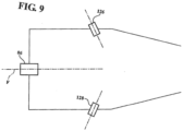
- the radial main fuel injection system 120 generally includes a radially outer fuel injection manifold 122 (illustrated schematically) and/or a radially inner fuel injection manifold 124 (illustrated schematically) with a respective multiple of outer fuel nozzles 126 and a multiple of inner fuel nozzles 128.
- the radially outer fuel injection manifold 122 and/or a radially inner fuel injection manifold 124 may be mounted to the diffuser case module 64 and/or to the shell 68, 70, however, various mount arrangements may alternatively or additionally provided.
- Each of the multiple of outer fuel nozzles 126 inner fuel nozzles 128 are located within a respective mixer 130, 132 to mix the supply of fuel with the pressurized air within the diffuser case module 64.
- a “mixer” as compared to a “swirler” may generate, for example, zero swirl, a counter-rotating swirl, a specific swirl which provides a resultant swirl or a residual net swirl which may be further directed at an angle. It should be appreciated that various combinations thereof may alternatively be utilized.
- the radial main fuel injection system 120 may include only the radially outer fuel injection manifold 96 with the multiple of outer fuel nozzles 126; only the radially inner fuel injection manifold 124 with the multiple of inner fuel nozzles 128; or both (shown). It should be appreciated that the radial main fuel injection system 120 may include single sets of outer fuel nozzles 126 and inner fuel nozzles 128 (shown) or multiple axially distributed sets of, for example, relatively smaller fuel nozzles.
- the radial main fuel injection system 120 may be circumferentially arranged in a multiple of configurations.
- the multiple of outer fuel nozzles 126 and the multiple of inner fuel nozzles 128 are circumferentially arranged so that the nozzles 126, 128 are directly opposed ( Figure 5 ).
- the multiple of outer fuel nozzles 126 and the multiple of inner fuel nozzles 128 are circumferentially staggered so that the nozzles 126, 128 are not directly opposed ( Figure 6 ).
- nozzles 126, 128 may be angled perpendicularly ( Figure 7 ), tangentially ( Figure 8 ), or at an angle such as downstream ( Figure 9 ) relative to the cross flow from the fuel nozzles 86 of the axial pilot fuel injection system 92 that are directed along axis F.
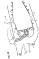
- the multiple of outer fuel nozzles 126 may be positioned through the outer liner 72 opposite or staggered relative to a non-fueled mixer 132' on the inner liner 74 ( Figure 10 ). That is, the non-fueled mixer 132' provides airflow but not fuel.
- the lean-staging is accomplished by axially distributing the fuel injection with a front-end pilot injector and a downstream main injector to axially distribute the heat release similar to an RQL designs, but with lean/lean combustion to enable low NOx and PM emissions. This is different than radial staged designs where all the fuel is injected at the front-end of the combustor. Moving the heat release away from the front-end can be a pressure anti-node for longitudinal acoustic modes to decrease coupling with these modes.
- the forward fuel nozzles 86 are circumferentially spaced apart between about 80% - 200% of a bulkhead height B.
- the bulkhead height B as defined herein is the radial distance between the liner panels 72, 74 at the forward end of the combustion chamber 66 at the bulkhead liner panels 98 of bulkhead assembly 84.
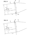
- the multiple of outer fuel nozzles 126 and the inner fuel nozzles 128 are axially spaced a distance D between 50% - 150% of the bulkhead height B aft of the forward fuel nozzles 86.
- outer fuel nozzles 126 are radially spaced a distance R from the inner fuel nozzles 128 at between about 100% - 200% of the bulkhead height B. It should be understood that the distance R may be with respect to the liner panels 72, 74 should the radial main fuel injection system 120 only utilize outer fuel nozzles 126 ( Figure 12 ) or inner fuel nozzles 128 ( Figure 13 ).
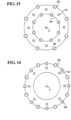
- the multiple of outer fuel nozzles 126 and multiple of inner fuel nozzles 128 may be arranged circumferentially in-line with the forward fuel nozzles 86.
- the multiple of outer fuel nozzles 126 and multiple of inner fuel nozzles 128 may be arranged circumferentially between the forward fuel nozzles 86 at, for example, quarter pitch ( Figure 15 ).
- the multiple of outer fuel nozzles 126 and/or the multiple of inner fuel nozzles 128 may be spaced apart a distance C of between 25% - 100% of the bulkhead height B circumferentially, which alternatively, may be defined as about 1.5 - 5 fuel jet diameters. It should be appreciated that various circumferential and other relationships may be utilized and that fuel jet diameter and bulkhead sizing are but examples thereof.
- the multiple of outer fuel nozzles 126 may be more numerous than the forward fuel nozzles 86. In this disclosed non-limiting embodiment, twice the number of outer fuel nozzles 126 as compared to the forward fuel nozzles 86.
- the multiple of outer fuel nozzles 126 include both in-line and circumferentially distributed forward fuel nozzles 86
- the axial pilot fuel injection system 92, the radial main fuel injection system 120 and the multiple of dilution holes 116 define a forward combustion zone 140 axially between the bulkhead assembly 84 and the forward section of the radial main fuel injection system 120, as well as a downstream combustion zone 142 between the forward section of the radial main fuel injection system 120 and the combustor exit 100.
- the downstream combustion zone 142 is axially proximate the multiple of dilution holes 116.
- the axial pilot fuel injection system 92 provides about 10% - 35% of the combustor airflow
- the radial main fuel injection system 120 provides about 30% - 60% of combustor airflow
- the multiple of dilution holes 116 provide about 5% - 20% of the combustor airflow.
- these ranges of combustor airflow may define a total combustor airflow less than 100% with the remainder being cooling air flow.
- the radial main fuel injection system 120 decreases and vice-versa with the balance being from the multiple dilution holes 116.
- the axial pilot fuel injection system 92 provides about 20% of the combustor airflow
- the radial main fuel injection system 120 provides about 45% of combustor airflow
- the multiple of dilution holes 116 provide about 10% of the combustor airflow with the remainder being cooling airflow.
- the forward combustion zone 140 defines about 20% to 50% of the total combustor chamber 66 volume and the downstream combustion zone 142 defines about 50% to 80% of the total combustor chamber 66 volume.
- the downstream combustion zone 142 forms an axial length L of about 100% - 250% a height H of the combustion chamber 66 between the liners 72, 74 at the radial main fuel injection system 120 location.
- the height H as defined herein is the radial distance between the liner panels 72, 74 within the combustion chamber 66 proximate the radial main fuel injection system 120 location. It should be appreciated that various combinations of the above-described geometries may be provided.
- a pilot/main fuel schedule controls how the fuel flow may be shifted between the axial pilot fuel injection system 92 and the radial main fuel injection system 120 to alter the heat release distribution and convective time delays associated with each zone and enable de-tuning away from instabilities.
- the approach can be used to mitigate both Rayleigh gain type thermoacoustic instabilities and entropy mode type instabilities.
- the range of fuel shifting possible will be constrained by other combustor requirements for emissions, efficiency, LBO, etc. Movement of the heat release away from the front-end which can be a pressure anti-node for longitudinal modes decreases coupling with these modes.
- the fuel percentage split between the axial pilot fuel injection system 92 and the radial main fuel injection system 120 is scheduled accordingly, based on, for example, engine power level or other operating condition to, for example, mitigate combustor tones or control other combustor performance metrics.
- the engine operating parameter may include, for example, at least one of engine power, throttle position, total fuel flow, and an aircraft flight condition and the combustor metric may include at least one of combustor tones, emissions, combustor efficiency, lean blow-out margin, and altitude re-light capability, etc.
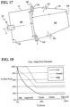
- a nominal fuel schedule is correlated as a percentage of the axial pilot fuel injection system 92, e.g., pilot fuel flow, with respect to an operating condition, e.g., engine power include at least one of combustor tones, emissions, combustor efficiency, lean blow-out margin, and altitude re-light capability, etc.
- a nominal fuel schedule is correlated as a percentage of the axial pilot fuel injection system 92, e.g., pilot fuel flow, with respect to an operating condition, e.g., engine power level.
- a low range and a high range envelope maintains the axial pilot fuel injection system 92, e.g., pilot fuel flow, and the radial main fuel injection system 120, e.g., main zone fuel flow, Fuel-Air (F/A) ratio within a desired limit for combustor operability.
- the fuel split is further optimized within this high-low range to mitigate combustor tones while also meeting other combustor metrics such as emissions, combustor efficiency, lean blow-out margin, altitude re-light capability, etc.
- a fuel-rich combustion environment in the forward combustion zone 140 is provided for low power operations.
- a fuel-lean combustion environment is maintained in both the forward combustion zone 140 and the downstream combustion zone 142.
- the method includes the step of selectively distributing the fuel being supplied between the forward combustion zone 140 and the downstream combustion zone 142 with 80% to 100% as the axial pilot fuel injection system 92 of fuel and with 0% to 20% as the radial main fuel injection system 120 flow of fuel.
- 40% to 100% as the flow of fuel may be supplied by the axial pilot fuel injection system 92 and 0% to 60% by the radial main fuel injection system 120.
- the gas turbine combustor and the method for operating the gas turbine combustor as disclosed herein provides for lower NOx emissions at low, mid and high power operation at generally equivalent weight and operability relative to a typical conventional gas turbine combustor.
- the forward combustion zone 140 may be robustly fueled to establish a fuel-rich combustion environment and provide for ignition, combustion stability, and low emissions.
- fuel flow to the downstream combustion zone 142 increases and fuel flow to the forward combustion zone 140 decreases whereby both combustion zones operate fuel lean in order to control NOx formation.
- the increased temperature of the combustion gases from the forward combustion zone 140 flow across the downstream combustion zone 142 to further facilitate stable combustion in the downstream zone and achievement of high combustion efficiency.
- the pilot/main fuel schedule permits control of combustion dynamics in an axially-staged lean-lean combustor configuration.
- the fuel split between the pilot and main is optimized to mitigate dynamics while also meeting all other combustor performance metrics.
- the fuel split between pilot & main is optimized to mitigate combustor tones. This alters the axial heat release distribution and associated convective time delays.
- Application of this method to a liquid-fueled aeroengine axially-staged lean-lean combustor configuration is new.
Landscapes
- Engineering & Computer Science (AREA)
- Chemical & Material Sciences (AREA)
- Combustion & Propulsion (AREA)
- Mechanical Engineering (AREA)
- General Engineering & Computer Science (AREA)
Claims (9)
- Verfahren zum Steuern eines Pilot-/Haupttreibstoffplans zu einer Ringbrennkammer (56) eines Gasturbinenmotors (20) eines Flugzeugs, umfassend:
Planen eines ersten Prozentsatzes eines gesamten Treibstoffflusses zu einem axialen Pilottreibstoffeinspritzsystem (92), das dazu betreibbar ist, den Treibstoff in eine vordere Verbrennungszone (140) eines Brennraums (56) im Allgemeinen entlang einer Achse (F) zuzuführen, und Planen eines zweiten Prozentsatzes des gesamten Treibstoffflusses zu einem radialen Haupttreibstoffeinspritzsystem (120), das mit einer stromabwärtigen Verbrennungszone des Brennraums (56) stromabwärts des axialen Pilottreibstoffeinspritzsystems (92) und im Allgemeinen quer zur Achse (F) verbunden ist, wobei das Planen Folgendes umfasst:
Korrelieren eines nominalen Treibstoffplans, der einen Bereich für den ersten und den zweiten Prozentsatz des gesamten Treibstoffdurchflusses umfasst, basierend auf einem Motorbetriebsparameter; dadurch gekennzeichnet, dass das Planen ferner Folgendes umfasst:
Optimieren des nominalen Treibstoffplans innerhalb des Bereichs, um Brennkammertöne abzuschwächen und gleichzeitig andere Brennkammermetriken einzuhalten, um den ersten und den zweiten Prozentsatz des gesamten Treibstoffflusses zu bestimmen. - Verfahren nach Anspruch 1, wobei der Motorbetriebsparameter eine Motorleistung beinhaltet.
- Verfahren nach Anspruch 2, wobei der nominale Treibstoffplan während der Leerlaufleistung einen Bereich des ersten Prozentsatzes von Treibstoff zum axialen Pilottreibstoffeinspritzsystem (92) zwischen 80 % und 100 % des gesamten Treibstoffflusses umfasst.
- Verfahren nach Anspruch 2 oder 3, wobei der nominale Treibstoffplan während der Anflugsleistung einen Bereich des ersten Prozentsatzes von Treibstoff zum axialen Pilottreibstoffeinspritzsystem (92) zwischen 40 % und 100 % des gesamten Treibstoffflusses umfasst.
- Verfahren nach einem der Ansprüche 2 bis 4, wobei der nominale Treibstoffplan während der Reiseflug-, Steigflug- und Startleistung einen Bereich des ersten Prozentsatzes von Treibstoff zum axialen Pilottreibstoffeinspritzsystem (92) zwischen 15 % und 50 % des gesamten Treibstoffflusses umfasst.
- Verfahren nach einem der vorhergehenden Ansprüche, wobei der Motorbetriebsparameter eine Drosselklappenstellung beinhaltet.
- Verfahren nach einem der vorhergehenden Ansprüche, wobei der Motorbetriebsparameter einen Flugzustand des Flugzeugs beinhaltet.
- Verfahren nach einem der vorhergehenden Ansprüche, ferner umfassend Planen des ersten Prozentsatzes und des zweiten Prozentsatzes des gesamten Treibstoffflusses als Reaktion auf den Motorbetriebsparameter, um eine Brennkammermetrik zu steuern.
- Verfahren nach Anspruch 8, wobei die Brennkammermetrik mindestens eines von Emissionen, Brennkammereffizienz, Magerflammabrissgrenze und Höhenwiederzündfähigkeit beinhaltet.
Applications Claiming Priority (1)
| Application Number | Priority Date | Filing Date | Title |
|---|---|---|---|
| US15/283,639 US10738704B2 (en) | 2016-10-03 | 2016-10-03 | Pilot/main fuel shifting in an axial staged combustor for a gas turbine engine |
Publications (2)
| Publication Number | Publication Date |
|---|---|
| EP3301361A1 EP3301361A1 (de) | 2018-04-04 |
| EP3301361B1 true EP3301361B1 (de) | 2025-05-14 |
Family
ID=59974260
Family Applications (1)
| Application Number | Title | Priority Date | Filing Date |
|---|---|---|---|
| EP17193551.3A Active EP3301361B1 (de) | 2016-10-03 | 2017-09-27 | Pilot-/haupttreibstoffwechsel in einer axialstufenbrennkammer für einen gasturbinenmotor |
Country Status (2)
| Country | Link |
|---|---|
| US (1) | US10738704B2 (de) |
| EP (1) | EP3301361B1 (de) |
Families Citing this family (19)
| Publication number | Priority date | Publication date | Assignee | Title |
|---|---|---|---|---|
| GB201904330D0 (en) | 2019-03-28 | 2019-05-15 | Rolls Royce Plc | Gas turbine engine combuster apparatus |
| EP3875742A1 (de) | 2020-03-04 | 2021-09-08 | Rolls-Royce plc | Gestufte verbrennung |
| GB2599423B (en) * | 2020-10-01 | 2025-05-28 | Bosch Thermotechnology Ltd Uk | Method for operating a combustion device, combustion device and heating unit |
| RU2753202C1 (ru) * | 2020-10-09 | 2021-08-12 | Открытое акционерное общество "Всероссийский дважды ордена Трудового Красного Знамени теплотехнический научно-исследовательский институт" (ОАО "ВТИ") | Малоэмиссионная камера сгорания с двумя зонами кинетического горения |
| RU2753203C1 (ru) * | 2020-10-09 | 2021-08-12 | Открытое акционерное общество "Всероссийский дважды ордена Трудового Красного Знамени теплотехнический научно-исследовательский институт" (ОАО "ВТИ") | Способ сжигания топлива в малоэмиссионной камере сгорания |
| CN114517920B (zh) * | 2020-11-19 | 2023-08-08 | 中国航发商用航空发动机有限责任公司 | 喷射装置、燃烧室头部、燃烧室和航空发动机 |
| US11725824B2 (en) * | 2021-04-08 | 2023-08-15 | Raytheon Technologies Corporation | Turbulence generator mixer for rotating detonation engine |
| CN113864063B (zh) * | 2021-09-28 | 2024-06-14 | 北京永旭腾风新能源动力科技发展有限公司 | 用于微燃机的双燃料系统、微燃机及其控制方法 |
| GB202205358D0 (en) | 2022-04-12 | 2022-05-25 | Rolls Royce Plc | Loading parameters |
| GB202205355D0 (en) | 2022-04-12 | 2022-05-25 | Rolls Royce Plc | Gas turbine operation |
| GB202205354D0 (en) * | 2022-04-12 | 2022-05-25 | Rolls Royce Plc | Fuel delivery |
| GB202219384D0 (en) | 2022-12-21 | 2023-02-01 | Rolls Royce Plc | Aircraft fuelling |
| GB202219385D0 (en) * | 2022-12-21 | 2023-02-01 | Rolls Royce Plc | Aircraft combustion systems |
| GB202219380D0 (en) | 2022-12-21 | 2023-02-01 | Rolls Royce Plc | Gas turbine operating conditions |
| US20240263590A1 (en) * | 2023-02-02 | 2024-08-08 | Pratt & Whitney Canada Corp | Fuel system with pilot and main injectors for hydrogen-driven gas turbine engine |
| US20240309810A1 (en) * | 2023-03-14 | 2024-09-19 | Raytheon Technologies Corporation | Introducing steam into core air upstream of turbine engine diffuser plenum |
| US20240401811A1 (en) * | 2023-05-31 | 2024-12-05 | General Electric Company | Turbine engine including a combustor |
| US12130016B1 (en) | 2023-05-31 | 2024-10-29 | General Electric Company | Turbine engine including a combustor |
| CN121162935A (zh) * | 2025-11-21 | 2025-12-19 | 中国航发湖南动力机械研究所 | 局部富油点熄火装置及航空发动机燃烧室 |
Family Cites Families (38)
| Publication number | Priority date | Publication date | Assignee | Title |
|---|---|---|---|---|
| US5749219A (en) * | 1989-11-30 | 1998-05-12 | United Technologies Corporation | Combustor with first and second zones |
| JPH05203148A (ja) * | 1992-01-13 | 1993-08-10 | Hitachi Ltd | ガスタービン燃焼装置及びその制御方法 |
| US5361586A (en) * | 1993-04-15 | 1994-11-08 | Westinghouse Electric Corporation | Gas turbine ultra low NOx combustor |
| US5647215A (en) * | 1995-11-07 | 1997-07-15 | Westinghouse Electric Corporation | Gas turbine combustor with turbulence enhanced mixing fuel injectors |
| US6715292B1 (en) | 1999-04-15 | 2004-04-06 | United Technologies Corporation | Coke resistant fuel injector for a low emissions combustor |
| GB9915770D0 (en) * | 1999-07-07 | 1999-09-08 | Rolls Royce Plc | A combustion chamber |
| US6481209B1 (en) | 2000-06-28 | 2002-11-19 | General Electric Company | Methods and apparatus for decreasing combustor emissions with swirl stabilized mixer |
| US6606861B2 (en) | 2001-02-26 | 2003-08-19 | United Technologies Corporation | Low emissions combustor for a gas turbine engine |
| US6484489B1 (en) | 2001-05-31 | 2002-11-26 | General Electric Company | Method and apparatus for mixing fuel to decrease combustor emissions |
| US6865889B2 (en) | 2002-02-01 | 2005-03-15 | General Electric Company | Method and apparatus to decrease combustor emissions |
| US6871501B2 (en) | 2002-12-03 | 2005-03-29 | General Electric Company | Method and apparatus to decrease gas turbine engine combustor emissions |
| US6862889B2 (en) | 2002-12-03 | 2005-03-08 | General Electric Company | Method and apparatus to decrease combustor emissions |
| US6868676B1 (en) * | 2002-12-20 | 2005-03-22 | General Electric Company | Turbine containing system and an injector therefor |
| GB0329626D0 (en) | 2003-12-23 | 2004-01-28 | Goodrich Control Sys Ltd | Fuel system |
| US7065972B2 (en) | 2004-05-21 | 2006-06-27 | Honeywell International, Inc. | Fuel-air mixing apparatus for reducing gas turbine combustor exhaust emissions |
| US7059135B2 (en) | 2004-08-30 | 2006-06-13 | General Electric Company | Method to decrease combustor emissions |
| JP4486549B2 (ja) * | 2005-06-06 | 2010-06-23 | 三菱重工業株式会社 | ガスタービンの燃焼器 |
| US7685823B2 (en) | 2005-10-28 | 2010-03-30 | Power Systems Mfg., Llc | Airflow distribution to a low emissions combustor |
| US7762073B2 (en) * | 2006-03-01 | 2010-07-27 | General Electric Company | Pilot mixer for mixer assembly of a gas turbine engine combustor having a primary fuel injector and a plurality of secondary fuel injection ports |
| US8028529B2 (en) | 2006-05-04 | 2011-10-04 | General Electric Company | Low emissions gas turbine combustor |
| US8001761B2 (en) * | 2006-05-23 | 2011-08-23 | General Electric Company | Method and apparatus for actively controlling fuel flow to a mixer assembly of a gas turbine engine combustor |
| US20090077973A1 (en) | 2007-09-20 | 2009-03-26 | Hamilton Sundstrand Corporation | Gas Turbine Fuel System for High Altitude Starting and Operation |
| JP4959524B2 (ja) * | 2007-11-29 | 2012-06-27 | 三菱重工業株式会社 | 燃焼バーナー |
| EP2107312A1 (de) * | 2008-04-01 | 2009-10-07 | Siemens Aktiengesellschaft | Pilotverbrennkammer in einem Brenner |
| US8112216B2 (en) * | 2009-01-07 | 2012-02-07 | General Electric Company | Late lean injection with adjustable air splits |
| JP4797079B2 (ja) * | 2009-03-13 | 2011-10-19 | 川崎重工業株式会社 | ガスタービン燃焼器 |
| US20100263382A1 (en) * | 2009-04-16 | 2010-10-21 | Alfred Albert Mancini | Dual orifice pilot fuel injector |
| EP2402652A1 (de) * | 2010-07-01 | 2012-01-04 | Siemens Aktiengesellschaft | Brenner |
| US9080770B2 (en) | 2011-06-06 | 2015-07-14 | Honeywell International Inc. | Reverse-flow annular combustor for reduced emissions |
| WO2013022367A1 (en) * | 2011-08-11 | 2013-02-14 | General Electric Company | System for injecting fuel in a gas turbine engine |
| US9631560B2 (en) * | 2011-11-22 | 2017-04-25 | United Technologies Corporation | Fuel-air mixture distribution for gas turbine engine combustors |
| US9400110B2 (en) | 2012-10-19 | 2016-07-26 | Honeywell International Inc. | Reverse-flow annular combustor for reduced emissions |
| EP3008391B1 (de) * | 2013-06-11 | 2020-05-06 | United Technologies Corporation | Brennkammer mit axialer stufung für einen gasturbinenmotor |
| EP3060851B1 (de) | 2013-10-24 | 2019-11-27 | United Technologies Corporation | Umfänglich und axial gestufte brennkammer für gasturbinenmotor |
| EP3060850B1 (de) | 2013-10-24 | 2020-05-13 | United Technologies Corporation | Umfänglich und axial gestufte ringbrennkammer für eine gasturbinenbrennkammer |
| US20150159877A1 (en) * | 2013-12-06 | 2015-06-11 | General Electric Company | Late lean injection manifold mixing system |
| US9551490B2 (en) * | 2014-04-08 | 2017-01-24 | General Electric Company | System for cooling a fuel injector extending into a combustion gas flow field and method for manufacture |
| US10001281B2 (en) * | 2015-04-17 | 2018-06-19 | General Electric Company | Fuel nozzle with dual-staged main circuit |
-
2016
- 2016-10-03 US US15/283,639 patent/US10738704B2/en active Active
-
2017
- 2017-09-27 EP EP17193551.3A patent/EP3301361B1/de active Active
Also Published As
| Publication number | Publication date |
|---|---|
| US20180163629A1 (en) | 2018-06-14 |
| US10738704B2 (en) | 2020-08-11 |
| EP3301361A1 (de) | 2018-04-04 |
Similar Documents
| Publication | Publication Date | Title |
|---|---|---|
| EP3301361B1 (de) | Pilot-/haupttreibstoffwechsel in einer axialstufenbrennkammer für einen gasturbinenmotor | |
| EP3008391B1 (de) | Brennkammer mit axialer stufung für einen gasturbinenmotor | |
| EP3301372B1 (de) | Umlaufende kraftstoffverlagerung und -beaufschlagung in einer axial gestuften brennkammer für einen gasturbinenmotor | |
| US11365884B2 (en) | Radial fuel shifting and biasing in an axial staged combustor for a gas turbine engine | |
| US11815268B2 (en) | Main mixer in an axial staged combustor for a gas turbine engine | |
| EP3404331B1 (de) | Gasturbinenbrennkammer mit einer brennstoffluftmischeranordnung | |
| EP3415819B1 (de) | Brennkammer für ein gastirbinenmotor umfassend auskleidungsplatten mit diffundiertem schnittstellendurchgang | |
| EP3301373B1 (de) | Pilotinjektorkraftstoffverlagerung in einer axial gestuften brennkammer für einen gasturbinenmotor | |
| EP3333486B1 (de) | Hauptmischer für eine gasturbinenmotorbrennkammer | |
| US9404657B2 (en) | Combuster with radial fuel injection | |
| WO2015100346A1 (en) | Multi-streamed dilution hole configuration for a gas turbine engine | |
| US11226102B2 (en) | Fuel nozzle for a gas turbine engine | |
| US12305571B2 (en) | Combustor | |
| EP3060852B1 (de) | Brennkammer für gasturbinenmotor mit quenchstrahlmuster |
Legal Events
| Date | Code | Title | Description |
|---|---|---|---|
| PUAI | Public reference made under article 153(3) epc to a published international application that has entered the european phase |
Free format text: ORIGINAL CODE: 0009012 |
|
| STAA | Information on the status of an ep patent application or granted ep patent |
Free format text: STATUS: THE APPLICATION HAS BEEN PUBLISHED |
|
| AK | Designated contracting states |
Kind code of ref document: A1 Designated state(s): AL AT BE BG CH CY CZ DE DK EE ES FI FR GB GR HR HU IE IS IT LI LT LU LV MC MK MT NL NO PL PT RO RS SE SI SK SM TR |
|
| AX | Request for extension of the european patent |
Extension state: BA ME |
|
| STAA | Information on the status of an ep patent application or granted ep patent |
Free format text: STATUS: REQUEST FOR EXAMINATION WAS MADE |
|
| 17P | Request for examination filed |
Effective date: 20181004 |
|
| RBV | Designated contracting states (corrected) |
Designated state(s): AL AT BE BG CH CY CZ DE DK EE ES FI FR GB GR HR HU IE IS IT LI LT LU LV MC MK MT NL NO PL PT RO RS SE SI SK SM TR |
|
| RAP1 | Party data changed (applicant data changed or rights of an application transferred) |
Owner name: RAYTHEON TECHNOLOGIES CORPORATION |
|
| STAA | Information on the status of an ep patent application or granted ep patent |
Free format text: STATUS: EXAMINATION IS IN PROGRESS |
|
| 17Q | First examination report despatched |
Effective date: 20210422 |
|
| RAP3 | Party data changed (applicant data changed or rights of an application transferred) |
Owner name: RTX CORPORATION |
|
| GRAP | Despatch of communication of intention to grant a patent |
Free format text: ORIGINAL CODE: EPIDOSNIGR1 |
|
| STAA | Information on the status of an ep patent application or granted ep patent |
Free format text: STATUS: GRANT OF PATENT IS INTENDED |
|
| INTG | Intention to grant announced |
Effective date: 20241204 |
|
| GRAS | Grant fee paid |
Free format text: ORIGINAL CODE: EPIDOSNIGR3 |
|
| GRAA | (expected) grant |
Free format text: ORIGINAL CODE: 0009210 |
|
| STAA | Information on the status of an ep patent application or granted ep patent |
Free format text: STATUS: THE PATENT HAS BEEN GRANTED |
|
| AK | Designated contracting states |
Kind code of ref document: B1 Designated state(s): AL AT BE BG CH CY CZ DE DK EE ES FI FR GB GR HR HU IE IS IT LI LT LU LV MC MK MT NL NO PL PT RO RS SE SI SK SM TR |
|
| REG | Reference to a national code |
Ref country code: GB Ref legal event code: FG4D |
|
| REG | Reference to a national code |
Ref country code: CH Ref legal event code: EP |
|
| REG | Reference to a national code |
Ref country code: IE Ref legal event code: FG4D |
|
| REG | Reference to a national code |
Ref country code: DE Ref legal event code: R096 Ref document number: 602017089431 Country of ref document: DE |
|
| REG | Reference to a national code |
Ref country code: NL Ref legal event code: MP Effective date: 20250514 |
|
| PG25 | Lapsed in a contracting state [announced via postgrant information from national office to epo] |
Ref country code: FI Free format text: LAPSE BECAUSE OF FAILURE TO SUBMIT A TRANSLATION OF THE DESCRIPTION OR TO PAY THE FEE WITHIN THE PRESCRIBED TIME-LIMIT Effective date: 20250514 Ref country code: PT Free format text: LAPSE BECAUSE OF FAILURE TO SUBMIT A TRANSLATION OF THE DESCRIPTION OR TO PAY THE FEE WITHIN THE PRESCRIBED TIME-LIMIT Effective date: 20250915 Ref country code: ES Free format text: LAPSE BECAUSE OF FAILURE TO SUBMIT A TRANSLATION OF THE DESCRIPTION OR TO PAY THE FEE WITHIN THE PRESCRIBED TIME-LIMIT Effective date: 20250514 |
|
| PGFP | Annual fee paid to national office [announced via postgrant information from national office to epo] |
Ref country code: DE Payment date: 20250820 Year of fee payment: 9 |
|
| REG | Reference to a national code |
Ref country code: LT Ref legal event code: MG9D |
|
| PG25 | Lapsed in a contracting state [announced via postgrant information from national office to epo] |
Ref country code: GR Free format text: LAPSE BECAUSE OF FAILURE TO SUBMIT A TRANSLATION OF THE DESCRIPTION OR TO PAY THE FEE WITHIN THE PRESCRIBED TIME-LIMIT Effective date: 20250815 Ref country code: NO Free format text: LAPSE BECAUSE OF FAILURE TO SUBMIT A TRANSLATION OF THE DESCRIPTION OR TO PAY THE FEE WITHIN THE PRESCRIBED TIME-LIMIT Effective date: 20250814 |
|
| PG25 | Lapsed in a contracting state [announced via postgrant information from national office to epo] |
Ref country code: NL Free format text: LAPSE BECAUSE OF FAILURE TO SUBMIT A TRANSLATION OF THE DESCRIPTION OR TO PAY THE FEE WITHIN THE PRESCRIBED TIME-LIMIT Effective date: 20250514 Ref country code: PL Free format text: LAPSE BECAUSE OF FAILURE TO SUBMIT A TRANSLATION OF THE DESCRIPTION OR TO PAY THE FEE WITHIN THE PRESCRIBED TIME-LIMIT Effective date: 20250514 |
|
| REG | Reference to a national code |
Ref country code: AT Ref legal event code: MK05 Ref document number: 1795041 Country of ref document: AT Kind code of ref document: T Effective date: 20250514 |
|
| PG25 | Lapsed in a contracting state [announced via postgrant information from national office to epo] |
Ref country code: BG Free format text: LAPSE BECAUSE OF FAILURE TO SUBMIT A TRANSLATION OF THE DESCRIPTION OR TO PAY THE FEE WITHIN THE PRESCRIBED TIME-LIMIT Effective date: 20250514 |
|
| PGFP | Annual fee paid to national office [announced via postgrant information from national office to epo] |
Ref country code: GB Payment date: 20250827 Year of fee payment: 9 |
|
| PG25 | Lapsed in a contracting state [announced via postgrant information from national office to epo] |
Ref country code: HR Free format text: LAPSE BECAUSE OF FAILURE TO SUBMIT A TRANSLATION OF THE DESCRIPTION OR TO PAY THE FEE WITHIN THE PRESCRIBED TIME-LIMIT Effective date: 20250514 |
|
| PG25 | Lapsed in a contracting state [announced via postgrant information from national office to epo] |
Ref country code: AT Free format text: LAPSE BECAUSE OF FAILURE TO SUBMIT A TRANSLATION OF THE DESCRIPTION OR TO PAY THE FEE WITHIN THE PRESCRIBED TIME-LIMIT Effective date: 20250514 |
|
| PGFP | Annual fee paid to national office [announced via postgrant information from national office to epo] |
Ref country code: FR Payment date: 20250820 Year of fee payment: 9 |
|
| PG25 | Lapsed in a contracting state [announced via postgrant information from national office to epo] |
Ref country code: RS Free format text: LAPSE BECAUSE OF FAILURE TO SUBMIT A TRANSLATION OF THE DESCRIPTION OR TO PAY THE FEE WITHIN THE PRESCRIBED TIME-LIMIT Effective date: 20250814 |
|
| PG25 | Lapsed in a contracting state [announced via postgrant information from national office to epo] |
Ref country code: IS Free format text: LAPSE BECAUSE OF FAILURE TO SUBMIT A TRANSLATION OF THE DESCRIPTION OR TO PAY THE FEE WITHIN THE PRESCRIBED TIME-LIMIT Effective date: 20250914 |
|
| PG25 | Lapsed in a contracting state [announced via postgrant information from national office to epo] |
Ref country code: LV Free format text: LAPSE BECAUSE OF FAILURE TO SUBMIT A TRANSLATION OF THE DESCRIPTION OR TO PAY THE FEE WITHIN THE PRESCRIBED TIME-LIMIT Effective date: 20250514 |
|
| PG25 | Lapsed in a contracting state [announced via postgrant information from national office to epo] |
Ref country code: SM Free format text: LAPSE BECAUSE OF FAILURE TO SUBMIT A TRANSLATION OF THE DESCRIPTION OR TO PAY THE FEE WITHIN THE PRESCRIBED TIME-LIMIT Effective date: 20250514 Ref country code: DK Free format text: LAPSE BECAUSE OF FAILURE TO SUBMIT A TRANSLATION OF THE DESCRIPTION OR TO PAY THE FEE WITHIN THE PRESCRIBED TIME-LIMIT Effective date: 20250514 |
|
| PG25 | Lapsed in a contracting state [announced via postgrant information from national office to epo] |
Ref country code: CZ Free format text: LAPSE BECAUSE OF FAILURE TO SUBMIT A TRANSLATION OF THE DESCRIPTION OR TO PAY THE FEE WITHIN THE PRESCRIBED TIME-LIMIT Effective date: 20250514 |
|
| PG25 | Lapsed in a contracting state [announced via postgrant information from national office to epo] |
Ref country code: EE Free format text: LAPSE BECAUSE OF FAILURE TO SUBMIT A TRANSLATION OF THE DESCRIPTION OR TO PAY THE FEE WITHIN THE PRESCRIBED TIME-LIMIT Effective date: 20250514 |
|
| PG25 | Lapsed in a contracting state [announced via postgrant information from national office to epo] |
Ref country code: SK Free format text: LAPSE BECAUSE OF FAILURE TO SUBMIT A TRANSLATION OF THE DESCRIPTION OR TO PAY THE FEE WITHIN THE PRESCRIBED TIME-LIMIT Effective date: 20250514 Ref country code: RO Free format text: LAPSE BECAUSE OF FAILURE TO SUBMIT A TRANSLATION OF THE DESCRIPTION OR TO PAY THE FEE WITHIN THE PRESCRIBED TIME-LIMIT Effective date: 20250514 |
|
| PG25 | Lapsed in a contracting state [announced via postgrant information from national office to epo] |
Ref country code: IT Free format text: LAPSE BECAUSE OF FAILURE TO SUBMIT A TRANSLATION OF THE DESCRIPTION OR TO PAY THE FEE WITHIN THE PRESCRIBED TIME-LIMIT Effective date: 20250514 |