EP3301302B1 - Scroll compressor and air-conditioning device - Google Patents
Scroll compressor and air-conditioning device Download PDFInfo
- Publication number
- EP3301302B1 EP3301302B1 EP16859450.5A EP16859450A EP3301302B1 EP 3301302 B1 EP3301302 B1 EP 3301302B1 EP 16859450 A EP16859450 A EP 16859450A EP 3301302 B1 EP3301302 B1 EP 3301302B1
- Authority
- EP
- European Patent Office
- Prior art keywords
- passage
- scroll
- scroll compressor
- lubricant oil
- oil
- Prior art date
- Legal status (The legal status is an assumption and is not a legal conclusion. Google has not performed a legal analysis and makes no representation as to the accuracy of the status listed.)
- Active
Links
Images


Classifications
-
- F—MECHANICAL ENGINEERING; LIGHTING; HEATING; WEAPONS; BLASTING
- F04—POSITIVE - DISPLACEMENT MACHINES FOR LIQUIDS; PUMPS FOR LIQUIDS OR ELASTIC FLUIDS
- F04C—ROTARY-PISTON, OR OSCILLATING-PISTON, POSITIVE-DISPLACEMENT MACHINES FOR LIQUIDS; ROTARY-PISTON, OR OSCILLATING-PISTON, POSITIVE-DISPLACEMENT PUMPS
- F04C18/00—Rotary-piston pumps specially adapted for elastic fluids
- F04C18/02—Rotary-piston pumps specially adapted for elastic fluids of arcuate-engagement type, i.e. with circular translatory movement of co-operating members, each member having the same number of teeth or tooth-equivalents
-
- F—MECHANICAL ENGINEERING; LIGHTING; HEATING; WEAPONS; BLASTING
- F04—POSITIVE - DISPLACEMENT MACHINES FOR LIQUIDS; PUMPS FOR LIQUIDS OR ELASTIC FLUIDS
- F04C—ROTARY-PISTON, OR OSCILLATING-PISTON, POSITIVE-DISPLACEMENT MACHINES FOR LIQUIDS; ROTARY-PISTON, OR OSCILLATING-PISTON, POSITIVE-DISPLACEMENT PUMPS
- F04C23/00—Combinations of two or more pumps, each being of rotary-piston or oscillating-piston type, specially adapted for elastic fluids; Pumping installations specially adapted for elastic fluids; Multi-stage pumps specially adapted for elastic fluids
- F04C23/008—Hermetic pumps
-
- F—MECHANICAL ENGINEERING; LIGHTING; HEATING; WEAPONS; BLASTING
- F04—POSITIVE - DISPLACEMENT MACHINES FOR LIQUIDS; PUMPS FOR LIQUIDS OR ELASTIC FLUIDS
- F04C—ROTARY-PISTON, OR OSCILLATING-PISTON, POSITIVE-DISPLACEMENT MACHINES FOR LIQUIDS; ROTARY-PISTON, OR OSCILLATING-PISTON, POSITIVE-DISPLACEMENT PUMPS
- F04C15/00—Component parts, details or accessories of machines, pumps or pumping installations, not provided for in groups F04C2/00 - F04C14/00
- F04C15/0088—Lubrication
- F04C15/0092—Control systems for the circulation of the lubricant
-
- F—MECHANICAL ENGINEERING; LIGHTING; HEATING; WEAPONS; BLASTING
- F04—POSITIVE - DISPLACEMENT MACHINES FOR LIQUIDS; PUMPS FOR LIQUIDS OR ELASTIC FLUIDS
- F04C—ROTARY-PISTON, OR OSCILLATING-PISTON, POSITIVE-DISPLACEMENT MACHINES FOR LIQUIDS; ROTARY-PISTON, OR OSCILLATING-PISTON, POSITIVE-DISPLACEMENT PUMPS
- F04C18/00—Rotary-piston pumps specially adapted for elastic fluids
- F04C18/02—Rotary-piston pumps specially adapted for elastic fluids of arcuate-engagement type, i.e. with circular translatory movement of co-operating members, each member having the same number of teeth or tooth-equivalents
- F04C18/0207—Rotary-piston pumps specially adapted for elastic fluids of arcuate-engagement type, i.e. with circular translatory movement of co-operating members, each member having the same number of teeth or tooth-equivalents both members having co-operating elements in spiral form
- F04C18/0215—Rotary-piston pumps specially adapted for elastic fluids of arcuate-engagement type, i.e. with circular translatory movement of co-operating members, each member having the same number of teeth or tooth-equivalents both members having co-operating elements in spiral form where only one member is moving
-
- F—MECHANICAL ENGINEERING; LIGHTING; HEATING; WEAPONS; BLASTING
- F04—POSITIVE - DISPLACEMENT MACHINES FOR LIQUIDS; PUMPS FOR LIQUIDS OR ELASTIC FLUIDS
- F04C—ROTARY-PISTON, OR OSCILLATING-PISTON, POSITIVE-DISPLACEMENT MACHINES FOR LIQUIDS; ROTARY-PISTON, OR OSCILLATING-PISTON, POSITIVE-DISPLACEMENT PUMPS
- F04C28/00—Control of, monitoring of, or safety arrangements for, pumps or pumping installations specially adapted for elastic fluids
- F04C28/08—Control of, monitoring of, or safety arrangements for, pumps or pumping installations specially adapted for elastic fluids characterised by varying the rotational speed
-
- F—MECHANICAL ENGINEERING; LIGHTING; HEATING; WEAPONS; BLASTING
- F04—POSITIVE - DISPLACEMENT MACHINES FOR LIQUIDS; PUMPS FOR LIQUIDS OR ELASTIC FLUIDS
- F04C—ROTARY-PISTON, OR OSCILLATING-PISTON, POSITIVE-DISPLACEMENT MACHINES FOR LIQUIDS; ROTARY-PISTON, OR OSCILLATING-PISTON, POSITIVE-DISPLACEMENT PUMPS
- F04C29/00—Component parts, details or accessories of pumps or pumping installations, not provided for in groups F04C18/00 - F04C28/00
- F04C29/02—Lubrication; Lubricant separation
- F04C29/021—Control systems for the circulation of the lubricant
-
- F—MECHANICAL ENGINEERING; LIGHTING; HEATING; WEAPONS; BLASTING
- F04—POSITIVE - DISPLACEMENT MACHINES FOR LIQUIDS; PUMPS FOR LIQUIDS OR ELASTIC FLUIDS
- F04C—ROTARY-PISTON, OR OSCILLATING-PISTON, POSITIVE-DISPLACEMENT MACHINES FOR LIQUIDS; ROTARY-PISTON, OR OSCILLATING-PISTON, POSITIVE-DISPLACEMENT PUMPS
- F04C29/00—Component parts, details or accessories of pumps or pumping installations, not provided for in groups F04C18/00 - F04C28/00
- F04C29/02—Lubrication; Lubricant separation
- F04C29/028—Means for improving or restricting lubricant flow
Definitions
- the present invention relates to a scroll compressor which compresses a fluid and an air-conditioning device.
- JP H05-141201 A discloses a scroll compressor according to the preamble of claim 1.
- a scroll compressor includes a fixed scroll and an orbiting scroll and the orbiting scroll orbits while being fitted to the fixed scroll to compress a fluid.
- a scroll compressor in which a pressure in a housing in which the fixed scroll and the orbiting scroll are accommodated is lower than a discharge pressure, and in this scroll compressor, a force in a direction away from the fixed scroll is applied to the orbiting scroll by compressing a fluid.
- a thrust bearing for supporting this force is installed. However, in the thrust bearing, a friction loss is caused when the orbiting scroll orbits, and there is a possibility that efficiency of the scroll compressor is decreased due to the friction loss.
- An object of the present invention is to prevent an efficiency of a scroll compressor from decreasing.
- a scroll compressor including: a housing; a partitioning member which divides an interior space of the housing into a first chamber and a second chamber; a scroll compression mechanism which includes a fixed scroll and an orbiting scroll disposed in the first chamber and compresses a refrigerant between the fixed scroll and the orbiting scroll to cause the compressed refrigerant to flow into the second chamber; a rotary shaft which is a rod-shaped member, includes an oil supply passage which extends in a longitudinal direction of the rod-shaped member and through which lubricant oil passes, and causes the orbiting scroll disposed on an outlet side of the oil supply passage to orbit; a back pressure chamber which is disposed on the rotary shaft side of the orbiting scroll and into which the lubricant oil flowing out from the oil supply passage flows; an oil drain passage through which the lubricant oil flowing into the back pressure chamber passes; and a flow control mechanism which changes a flow rate of the lubricant oil flowing through the oil drain passage.
- the pressure in the back pressure chamber increases by changing the flow rate of the lubricant oil flowing out from the inside of the back pressure chamber through the oil drain passage, and a force from the orbiting scroll toward the fixed scroll is generated on a rear surface of the orbiting scroll.
- a portion of a force which is applied to the orbiting scroll and is in a direction away from the fixed scroll is canceled out by the force generated on the rear surface of the orbiting scroll, and thus, a loss due to a friction generated when the orbiting scroll orbits in a thrust bearing is decreased.
- the flow control mechanism changes, as described in the independent claim 1, the flow rate of the lubricant oil flowing through the oil drain passage based on an orbital speed of the orbiting scroll. In this way, the force from the orbiting scroll toward the fixed scroll can be adjusted according to the orbital speed.
- the flow control mechanism increases the flow rate of the lubricant oil flowing through the oil drain passage when the orbital speed of the orbiting scroll is high compared to when the orbital speed of the orbiting scroll is low.
- the scroll compressor includes an oil supply pump which supplies the lubricant oil to the back pressure chamber.
- energy for driving the oil supply pump increases.
- the flow rate of the lubricant oil flowing through the oil drain passage increases when the orbital speed of the orbiting scroll is high, and thus, energy for driving the oil supply pump is prevented from increasing.
- the flow control mechanism increases the flow rate of the lubricant oil flowing through the oil drain passage in a case where the orbital speed of the orbiting scroll is larger than a threshold value compared to a case where the orbital speed of the orbiting scroll is equal to or smaller than the threshold value, and the threshold value is equal to or larger than an orbital speed equivalent to a case where the scroll compressor is operated with a capacity of 1/2 of a rated operation and may be equal to or smaller than an orbital speed equivalent to a case where the scroll compressor is operated with the capacity of the rated operation. Accordingly, it is possible to effectively prevent the efficiency of the scroll compressor from decreasing.
- the flow control mechanism may change the flow rate of the lubricant oil flowing through the oil drain passage based on at least one of a pressure of the refrigerant and a temperature of the lubricant oil. Accordingly, a change in an environment where the scroll compressor is used can be considered when the force from the fixed scroll toward the orbiting scroll is decreased, and thus, it is possible to adjust the force which is applied to the orbiting scroll and is in the direction away from the fixed scroll according to the change in the environment.
- a passage sectional area of the oil drain passage may be larger than a passage sectional area of the oil supply passage. According to this structure, a pressure loss of the oil drain passage can be smaller than a pressure loss of the oil supply passage, and thus, it is possible to increase the pressure in the back pressure chamber by the flow control mechanism.
- the scroll compressor may further include a bypass passage through which the lubricant oil in the back pressure chamber flows to bypass the flow control mechanism, in which a passage sectional area of the bypass passage may be smaller than the passage sectional area of the oil supply passage. According to this structure, it is possible to adjust the pressure in the back pressure chamber when the oil drain passage is closed.
- the scroll compressor may further include a bypass passage through which the lubricant oil in the back pressure chamber flows to bypass the flow control mechanism, in which the bypass passage may include a member provided with a passage having a passage sectional area which is smaller than the passage sectional area of the oil drain passage. According to this structure, it is possible to adjust the pressure in the back pressure chamber when the oil drain passage is closed.
- the scroll compressor may further include a positive-displacement oil supply pump which supplies the lubricant oil to the back pressure chamber via the oil supply passage.
- a positive-displacement oil supply pump which supplies the lubricant oil to the back pressure chamber via the oil supply passage.
- the flow control mechanism may set the flow rate of the lubricant oil flowing through the oil drain passage to be larger than 0 while the orbiting scroll orbits.
- the lubricant oil can be supplied to a sliding portion such as a slide bush or a thrust bearing during the operation of the scroll compressor, and thus, the sliding portion can be lubricated.
- an air-conditioning device including: a condenser which condenses a refrigerant; an evaporator which evaporates the refrigerant condensed by the condenser; and a scroll compressor which compresses the refrigerant evaporated by the evaporator.
- the air-conditioning device of the present invention includes the scroll compressor of the present invention, and thus, it is possible to prevent the efficiency from decreasing.
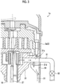
- Fig. 1 is an overall sectional view showing a scroll compressor 1 according to a first embodiment.
- Fig. 1 shows the scroll compressor 1 which compresses a sucked fluid, in the present embodiment, a refrigerant, and discharges the compressed refrigerant.
- the scroll compressor 1 is provided in a refrigerant flow path through which the refrigerant which is the fluid circulates in an air-conditioning device or a refrigerator.
- the scroll compressor 1 includes a motor 5 which is a drive device of the scroll compressor 1 and a scroll compression mechanism 7 which is driven by the motor 5 in an interior space of a housing 3.
- the housing 3 includes a tubular housing main body 3a which vertically extends, a bottom portion 3b which closes a lower end of the housing main body 3a, and a cover portion 3c which closes an upper end of the housing main body 3a.
- the housing 3 is a pressure container whose entirety is sealed.
- a suction pipe 9 through which the refrigerant is introduced into the housing 3 is provided on the side portion of the housing main body 3a.
- a discharge pipe 11 through which the refrigerant compressed by the scroll compression mechanism 7 is discharged is provided on the upper portion of the cover portion 3c.
- a discharge cover 13 is provided between the housing main body 3a and the cover portion 3c, and the interior space of the housing 3 is divided into a low-pressure chamber 3A which is a first chamber positioned below the discharge cover 13 which is a partitioning member and a high-pressure chamber 3B which is a second chamber positioned above the discharge cover 13. Even in a case where the discharge cover 13 is not provided in the housing 3, the fixed scroll 33 and the upper bearing 21 function as the partitioning member.
- the discharge cover 13 includes an opening hole 13a through which the low-pressure chamber 3A and the high-pressure chamber 3B communicate with each other.
- a discharge reed valve 13b which opens and closes the opening hole 13a is provided in the discharge cover 13.
- An oil reservoir in which the lubricant oil is stored is formed on the bottom in the housing 3.
- the motor 5 includes a stator 15 and a rotor 17.
- the stator 15 is fixed to an inner wall surface at an approximately intermediate portion in a vertical direction of the housing main body 3a.
- the rotor 17 is rotatably provided to the stator 15.
- a rotary shaft 19 is disposed above and below the rotor 17 in the longitudinal direction. Power is supplied to the motor 5 from the outside of the housing 3 to rotate the rotor 17, and thus, the rotor 17 and the rotary shaft 19 are rotated.
- the rotary shaft 19 is a rod-shaped member which causes an orbiting scroll 35 of the scroll compression mechanism 7 to orbit.
- the rotary shaft 19 is provided such that end portions protrude upward and downward from the rotor 17, and an upper end portion of the rotary shaft 19 is rotatably supported on the housing main body 3a by an upper bearing 21 and a lower end portion thereof is rotatably supported on the housing main body 3a by a lower bearing 23 about an axis CE extending in the vertical direction.
- the axis CE is a longitudinal direction of the rotary shaft 19 which is a rod-shaped member.
- an eccentric pin 25 which protrudes upward along an eccentricity LE eccentric to the axis CE is formed on an upper end of the rotary shaft 19.
- the scroll compression mechanism 7 is connected to the upper end of the rotary shaft 19 having the eccentric pin 25.
- the rotary shaft 19 and the eccentric pin 25 has an oil supply passage 27 which extends up and down, that is, in the longitudinal direction of the rotary shaft 19 on the insides of the rotary shaft 19 and the eccentric pin 25.
- the oil supply passage 27 penetrates the rotary shaft 19 from one end toward the other end.
- the oil supply passage 27 and the rotary shaft 19 are provided such that lower ends thereof reach the oil reservoir, and an oil supply pump 29 is provided on the lower end of the rotary shaft 19.
- the oil supply pump 29 is driven by the rotary shaft 19.
- the oil supply pump 29 feeds the lubricant oil stored in the oil reservoir to the oil supply passage 27 of the rotary shaft 19 according to the rotation of the rotary shaft 19.
- the lubricant oil fed by the oil supply pump 29 passes through the oil supply passage 27 and flows out from an outlet 27H which is provided on the end portion on the scroll compression mechanism 7 side.
- the oil supply pump 29 increases a flow rate of the discharged lubricant oil according to an increase in a rotational speed of the rotary shaft 19, that is, a rotational speed of the motor 5.
- the oil supply pump 29 is a positive-displacement pump and a centrifugal pump.
- the present invention is not limited to this.
- the positive-displacement pump as the oil supply pump 29, it is possible to relatively easily increase the pressure of the lubricant oil in the back pressure chamber 50 even in a case where an oil drain passage 21c is narrowed.
- the upper end portion of the rotary shaft 19 penetrates the upper bearing 21, and thus, the upper bearing rotatably supports the rotary shaft 19.
- a recessed portion 21a is formed on an upper surface of the upper bearing 21 to surround an upper end portion of the rotary shaft 19 penetrating the upper bearing 21.
- a slide bush 37 described later is accommodated in the recessed portion 21a, and the lubricant oil fed via the oil supply passage 27 by the oil supply pump 29 is stored in the recessed portion 21a.
- a notch 21b is formed on a portion of an outer periphery to have a gap between an inner wall surface of the housing main body 3a of the housing 3 and the upper bearing 21, and the oil drain passage 21c which communicates with the notch 21b and the recessed portion 21a is formed.
- a cover plate 31 is provided below the notch 21b of the upper bearing 21.
- the cover plate 31 is provided to extend in the vertical direction.
- the cover plate 31 is formed such that both side ends are curved toward the inner wall surface of the housing main body 3a so as to cover the vicinity of the notch 21b, and is formed such that a lower end of the cover plate 31 is gradually bent toward the inner wall surface of the housing main body 3a.
- the lubricant oil excessively stored in the recessed portion 21a flows to the recovery passage 51 through the oil drain passage 21c.
- the lubricant oil flowing through the recovery passage 51 is returned to a bottom oil reservoir in the housing 3.
- the scroll compression mechanism 7 is disposed above the upper bearing 21 in the low-pressure chamber 3A below the discharge cover 13, and includes a fixed scroll 33, an orbiting scroll 35, and a slide bush 37.
- a spiral fixed wrap 33b is formed on an inner surface (lower surface in Fig. 1 ) of the fixed end plate 33a fixed to the interior space of the housing 3.
- a discharge hole 33c is formed at the center portion of the fixed end plate 33a.
- a spiral movable wrap 35b is formed on an inner surface (upper surface in Fig. 1 ) of a movable end plate 35a facing the inner surface of the fixed end plate 33a in the fixed scroll 33.
- the movable wrap 35b of the orbiting scroll 35 and the fixed wrap 33b of the fixed scroll 33 mesh with each other with their phases shifted from each other, and thus, a compression chamber which is portioned by the fixed end plate 33a, the movable end plate 35a, the fixed wrap 33b, and the movable wrap 35b is formed.
- a cylindrical boss 35c to which the eccentric pin 25 of the rotary shaft 19 is connected and an eccentric rotation of the eccentric pin 25 is transmitted is formed on the outer surface (lower surface in Fig. 1 ) of the movable end plate 35a.
- the boss 35c is disposed on the outlet 27H side of the oil supply passage 27 included in the rotary shaft 19.
- the outlet 27H of the oil supply passage 27 faces the movable end plate 35a of the orbiting scroll 35.
- the orbiting scroll 35 is revolved while being prevented from rotating on the basis of the eccentric rotation of the eccentric pin 25 by a rotation prevention mechanism 39 such as an Oldham link disposed between the outer surface of the movable end plate 35a and the upper bearing 21.
- the slide bush 37 is accommodated in the recessed portion 21a of the above-described upper bearing 21, is interposed between the eccentric pin 25 of the rotary shaft 19 and the boss 35c of the orbiting scroll 35, and transmits the rotation of the eccentric pin 25 to the orbiting scroll 35.
- the recessed portion 21a in which the slide bush 37 is accommodated is appropriately referred to as a bush chamber 21a.
- the slide bush 37 is provided to be slidable in a radial direction of the eccentric pin 25 to maintain meshing between the movable wrap 35b of the orbiting scroll 35 and the fixed wrap 33b of the fixed scroll 33.
- a space formed by a rear surface 35ab of the orbiting scroll 35 that is, a surface facing the upper bearing 21 of the movable end plate 35a, the bush chamber 21a, and the upper bearing 21 is referred to as a back pressure chamber 50.
- the back pressure chamber 50 is disposed between the orbiting scroll 35 and the upper bearing 21 which rotatably supports the rotary shaft 19 on the orbiting scroll 35 side.
- the lubricant oil passing through the oil supply passage 27 from the outlet 27H of the oil supply passage 27 included in the rotary shaft 19 flows into the bush chamber 21a forming the back pressure chamber 50. That is, the lubricant oil flowing out from the oil supply passage 27 flows into the back pressure chamber 50.
- the lubricant oil flowing into the back pressure chamber 50 passes through the above-described oil drain passage 21c and is discharged from the back pressure chamber 50.
- a pressure in the low-pressure chamber 3A is the same as a suction pressure which is a pressure by which the scroll compression mechanism 7 sucks the refrigerant
- the orbiting scroll 35 of the scroll compression mechanism 7 receives a force in a direction away from the fixed scroll 33 by the refrigerant during compression of the refrigerant.
- this force is appropriately referred to as a thrust force.
- This force is supported by a thrust bearing 40 installed on the upper surface of the upper bearing 21.
- This thrust force is applied to the thrust bearing 40, and thus, when the orbiting scroll 35 orbits, a loss is caused by a friction between the rear surface 35ab of the orbiting scroll 35 and the thrust bearing 40.
- the loss caused by the friction is appropriately referred to as a thrust loss.
- the scroll compressor 1 causes the lubricant oil passing through the oil supply passage 27 of the rotary shaft 19 to flow into the back pressure chamber 50, and restrains a flow rate of the lubricant oil flowing out from the back pressure chamber 50 through the oil drain passage 21c, that is, a flow rate of the lubricant oil passing through the oil drain passage 21c.
- the pressure of the lubricant oil in the back pressure chamber 50 is larger than the suction pressure of the scroll compression mechanism 7, that is, the pressure in the low-pressure chamber 3A, and thus, the thrust force applied to the scroll compression mechanism 7 is decreased by the lubricant oil in the back pressure chamber 50.
- the thrust loss decreases.
- the recovery passage 51 is a passage which is connected to the oil drain passage 21c and the oil supply pump 29 side of the housing main body 3a. In the present embodiment, the recovery passage 51 is disposed outside the housing 3. However, the recovery passage 51 may be disposed inside the housing 3.
- the oil reservoir 3bt is disposed on the side to which gravity is applied.
- a lower portion of the scroll compressor 1 is the oil reservoir 3bt side, that is, the bottom portion 3b side, and an upper portion of the scroll compressor 1 is the cover portion 3c side. This is similarly applied to the following embodiments.
- a flow control mechanism is provided in the recovery passage 51.
- the flow control mechanism is a mechanism which changes the flow rate of the lubricant oil flowing through the oil drain passage 21c, and in the present embodiment, is a valve 52.
- the valve 52 has a mechanism which changes an area of a portion through which the lubricant oil passes.
- there is an on/off valve or a flow regulating valve. Opening, closing, and an opening degree of the valve 52 are controlled by a control device 53.
- an electromagnetic valve is used as the valve 52.
- the control device 53 is a computer having a processor and a memory.
- the control device 53 may be a control device of the air-conditioning device on which the scroll compressor 1 is mounted or may be a dedicated device for controlling the operation of the valve 52.
- the flow rate of the lubricant oil flowing through the recovery passage 51 is changed by opening or closing the valve 52 or adjusting the opening degree thereof, and thus, it is possible to change the flow rate of the lubricant oil flowing through the oil drain passage 21c connected to an upstream side in a flow direction of the lubricant oil flowing through the recovery passage 51.
- the valve 52 is provided in the recovery passage 51.
- the valve 52 may be provided in the oil drain passage 21c.
- the valve 52 may be provided between an inlet of the oil drain passage 21c and an inlet of the oil supply pump 29.
- the valve 52 may be provided between the inlet of the oil drain passage 21c and an outlet of the recovery passage 51.
- the flow rate of the lubricant oil flowing through the oil drain passage 21c also becomes smaller than that of the current state. Accordingly, the lubricant oil in the back pressure chamber 50 increases, and the inside of the back pressure chamber 50 is filled with the lubricant oil. Therefore, the pressure in the back pressure chamber 50 increases, the orbiting scroll 35 receives a force in a direction away from the upper bearing 21, that is, a force from the orbiting scroll 35 toward the fixed scroll 33, by the pressure from the back pressure chamber 5.
- this force is appropriately referred to as an anti-thrust force.
- This anti-thrust force is applied in a direction opposite to that of the thrust force, and thus, decreases the thrust force. That is, in a case where the flow rate of the lubricant oil flowing through the oil drain passage 21c is smaller than that of the current state, the thrust force decreases, and thus, a thrust loss decreases. As a result, the efficiency of the scroll compressor 1 is prevented from decreasing.
- the surplus of the lubricant oil flows to a portion between the upper bearing 21 and the orbiting scroll 35.
- the lubricant oil flows into the compression chamber along with the refrigerant, an oil film is formed inside the scroll compression mechanism 7 to improve sealing performance, and thus, it is possible to suppress a decrease in efficiency of the scroll compressor 1. That is, the lubricant oil flowing to the portion between the upper bearing 21 and the orbiting scroll 35 from the back pressure chamber 50 improves the sealing performance of the refrigerant in the scroll compression mechanism 7.
- the thrust loss is decreased, and performance of sealing the refrigerant in the scroll compression mechanism 7 is improved.
- the efficiency of the scroll compressor 1 is further prevented from decreasing.
- the anti-thrust force is generated by changing the flow rate of the lubricant oil flowing through the oil drain passage 21c, that is, the flow rate of the lubricant oil flowing out from the back pressure chamber 50, and thus, the thrust force is decreased and the thrust loss is decreased.
- the anti-thrust force is increased by decreasing the flow rate of the lubricant oil flowing through the oil drain passage 21c.
- the anti-thrust force is generated by setting the flow rate of the lubricant oil flowing through the oil drain passage 21c to 0, that is, by completely closing the valve 52.
- the flow rate of the lubricant oil flowing through the oil drain passage 21c may not be set to 0.
- the valve 52 may increase the flow rate of the lubricant oil flowing through the oil drain passage 21c to be greater than 0.
- the lubricant oil can be reliably supplied to a sliding portion such as a bearing, and thus, it is possible to reliably lubricate the sliding portion.
- a passage sectional area of the oil drain passage 21c is not limited.
- the passage sectional area may be equal to or larger than a passage sectional area of the oil supply passage 27 included in the rotary shaft 19.
- a pressure loss of the oil drain passage 21c can be smaller than a pressure loss of the oil supply passage 27, and thus, it is possible to reliably increase the pressure in the back pressure chamber 50 by the valve 52.
- the valve 52 is fully open, it is possible to reliably discharge the lubricant oil in the back pressure chamber 50 from the oil drain passage 21c.
- the valve 52 changes the flow rate of the lubricant oil flowing through the oil drain passage 21c based on the orbital speed of the orbiting scroll 35, that is, the rotational speed of the motor 5. For example, in a case where the orbital speed of the orbiting scroll 35 is larger than a threshold value, the valve 52 increases the flow rate of the lubricant oil flowing through the oil drain passage 21c compared to a case where the orbital speed is equal to or smaller than the threshold value.
- the valve 52 decreases the flow rate of the lubricant oil flowing through the oil drain passage 21c compared to the case where the orbital speed of the orbiting scroll 35 is larger than the threshold value.
- the flow rate of the lubricant oil flowing through the oil drain passage 21c becomes 0. In this way, in the case where the orbital speed of the orbiting scroll 35 is larger than the threshold value, the flow rate of the lubricant oil flowing through the oil drain passage 21c increases, and thus, drive power of the oil supply pump 29 is prevented from increasing.
- the threshold value of the orbital speed is set to 1/2 of the maximum orbital speed of the orbiting scroll 35.
- the threshold value may be 1/3 or 1/4 thereof.
- the threshold value may be an orbital speed which is most frequently used in the scroll compressor 1.
- the threshold value of the orbital speed may be equal to or larger than an orbital speed equivalent to a case where the scroll compressor 1 is operated with capacity of 1/2 of a rated operation or may be equal to or smaller than an orbital speed equivalent to a case where the scroll compressor 1 is operated with capacity of the rated operation. In a case where the threshold value is set to this range, the efficiency of the scroll compressor 1 is effectively prevented from decreasing.
- the sealing performance of the scroll compression mechanism 7 decreases.
- the amount of the lubricant oil flowing to the portion between the upper bearing 21 and the orbiting scroll 35 from the inside of the back pressure chamber 50 increases, and thus, the sealing performance of the scroll compression mechanism 7 is improved. As a result, the efficiency of the scroll compression mechanism 7 is prevented from decreasing.
- the scroll compressor 1 is used in an air-conditioning device.
- the air-conditioning device a period in which the air-conditioning device is operated under a condition of a lower output than the rated operation is longer than the period of the rated operation, preventing efficiency under such conditions from decreasing leads to preventing the efficiency from decreasing throughout the year.
- the orbital speed of the orbiting scroll 35 of the scroll compressor 1 is lower than the orbital speed of the orbiting scroll 35 when the rated operation is performed.
- the valve 52 is closed to decrease the flow rate of the lubricant oil flowing through the oil drain passage 21c.
- the scroll compressor 1 prevents the efficiency of the air-conditioning device from decreasing in a period in which the air-conditioning device is operated under a condition of a lower output than the output of the rated operation, and thus, it is possible to prevent the efficiency from decreasing throughout the year.
- valve 52 decreases the flow rate of the lubricant oil flowing through the oil drain passage 21c compared to when the rotational speed of the orbiting scroll 35 is high, and thus, it is possible to prevent the efficiency of the scroll compressor 1 from decreasing.
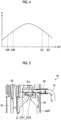
- Fig. 2 is a diagram showing a relationship between the opening degree of the valve 52 included in the scroll compressor 1 according to the first embodiment and the orbital speed of the orbiting scroll 35 included in the scroll compressor 1.
- the opening degree is changed as the orbital speed of the orbiting scroll 35 increases, and in the present embodiment, the opening degree may increase. That is, the flow rate of the lubricant oil flowing through the oil drain passage 21c may increase as the orbital speed of the orbiting scroll 35 increases.
- the opening degree of the valve 52 increases in a range of the orbital speed from N1 to N2. In this way, the flow rate of the lubricant oil flowing through the oil drain passage 21c can be optimally adjusted in the entire operation region of the scroll compressor 1, and thus, it is possible to further prevent the efficiency of the scroll compressor 1 from decreasing.
- the flow rate of the lubricant oil flowing through the oil drain passage 21c may be changed based on at least one of the pressure of the refrigerant and the temperature of the lubricant oil in addition to the orbital speed of the orbiting scroll 35.
- the pressure of the refrigerant a pressure difference between the discharge pressure of the refrigerant discharged from the scroll compressor 1 and the suction pressure of the refrigerant sucked into the scroll compressor 1 can be used.
- the pressure difference of the refrigerant increases as the rotational speed of the orbiting scroll 35 increases. Accordingly, for example, it is possible to increase the opening degree of the valve 52, that is, it is possible to increase the flow rate of the lubricant oil flowing through the oil drain passage 21c as the pressure difference of the refrigerant increases.
- the temperature of the lubricant oil is the temperature of the lubricant oil in the oil reservoir 3bt.
- the valve 52 can change the flow rate of the lubricant oil flowing through the oil drain passage 21c based on at least one of the rotational speed of the orbiting scroll 35, the pressure of the refrigerant, and the temperature of the lubricant oil.
- the flow rate of the lubricant oil flowing through the oil drain passage 21c is changed based on the rotational speed of the orbiting scroll 35, and the flow rate of the lubricant oil flowing through the oil drain passage 21c is changed based on at least one of the pressure of the refrigerant and the temperature of the lubricant oil.
- one oil drain passage 21c may be provided, and the number of the oil drain passages 21c may not be limited.
- the valve 52 is provided in each of the oil drain passages 21c, and the opening, the closing, or the opening degree of the valve 52 may be adjusted based on at least one of an operation conditions and an environment condition of the scroll compressor 1. Accordingly, the thrust force can be decreased in the entire operation region of the scroll compressor 1, a change in the environment where the scroll compressor 1 is used can be considered in the decrease of the thrust force, and thus, it is possible to further prevent the efficiency of the scroll compressor 1 from decreasing.
- the flow rate of the lubricant oil flowing through the oil drain passage 21c may be adjusted based on the pressure of the lubricant oil in the back pressure chamber 50.
- the opening degree of the valve 52 may be changed such that the pressure of the lubricant oil in the back pressure chamber 50 becomes a predetermined value.
- the anti-thrust force having a constant magnitude is generated, and thus, it is possible to decrease the thrust loss.
- a value which is detected by a pressure sensor provided in the oil drain passage 21c can be used as the pressure in the back pressure chamber 50.
- the recovery passage 51 is disposed outside the housing 3. According to this configuration, the valve 52 is easily provided in the recovery passage 51. In addition, preferably, a degree of freedom in the disposition of the valve 52 is improved.
- the recovery passage 51 and the valve 52 may be disposed inside the housing 3.
- the pressure in the back pressure chamber 50 increases, and thus, the anti-thrust force is generated.
- a portion of the thrust force is canceled out by the anti-thrust force generated, and thus, the thrust loss decreases, and the efficiency of the scroll compressor 1 is prevented from decreasing.
- Fig. 3 is a partial sectional view of the scroll compressor 1a according to a second embodiment.
- the scroll compressor 1a includes a bypass passage 21d through which the lubricant oil in the back pressure chamber 50 flows to bypass the valve 52 which is the flow control mechanism.
- the bypass passage 21d is a passage branching off from the oil drain passage 21c, and the lubricant oil flowing out from the oil drain passage 21c bypasses the valve 52 and flows through the bypass passage 21d.
- Other structures are similar to those of the scroll compressor 1 of the first embodiment.
- the oil drain passage 21c and the bypass passage 21d are provided in the upper bearing 21.
- the bypass passage 21d is provided inside the housing 3.
- the valve 52 which is the flow control mechanism is not provided in the bypass passage 21d.
- the recovery passage 51 in which the valve 52 is provided is disposed outside the housing 3.
- the recovery passage 51 penetrates the housing 3 and is connected to the oil drain passage 21c.
- a sectional shape of the bypass passage 21d is not limited, and for example, may be any one of a circular shape, an elliptical shape, or a polygonal shape. This is similarly applied to the following.
- the lubricant oil flowing out from the bypass passage 21d passes through a passage 54 between the cover plate 31 and the inside of the housing main body 3a, and thereafter, flows into the oil reservoir 3bt shown in Fig. 1 .
- the lubricant oil passing through the recovery passage 51 and the valve 52 flows into the housing main body 3a, and thereafter, flows into the oil reservoir 3bt shown in Fig. 1 .
- a passage sectional area of the bypass passage 21d is smaller than a passage sectional area of the oil supply passage 27 included in the rotary shaft 19 and a passage sectional area of the oil drain passage 21c.
- the bypass passage 21d is provided in the oil drain passage 21c, and thus, the lubricant oil in the oil drain passage 21c flows through the bypass passage 21d when the valve 52 is closed. Accordingly, compared to a case where the bypass passage 21d is not provided, it is possible to decrease the pressure in the back pressure chamber 50.
- Fig. 4 is a diagram showing a relationship between efficiency ⁇ of the scroll compressor 1a and a magnitude ⁇ P of increasing the pressure in the back pressure chamber 50. It is possible to adjust the pressure in the back pressure chamber 50 when the valve 52 is closed by changing the passage sectional area of the bypass passage 21d. As shown in Fig. 4 , as an example, the passage sectional area of the bypass passage 21d is adjusted such that the magnitude ⁇ P of increasing the pressure in the back pressure chamber 50 by the lubricant oil supplied into the back pressure chamber 50 from the oil supply pump 29 is from 0.02 MPa to 0.5 MPa or from 0.05 MPa to 0.3 MPa. The pressure in the back pressure chamber 50 is adjusted by adjusting the passage sectional area of the bypass passage 21d, and thus, it is possible to maximize the efficiency ⁇ of the scroll compressor 1a.
- bypass passage 21d penetrates the upper bearing 21 from the motor 5 side toward the oil drain passage 21c.
- the bypass passage 21d may be an orifice or a capillary.
- Fig. 5 is a partial sectional view of a scroll compressor 1b according to a first modification example of the second embodiment.
- the scroll compressor 1b has a structure similar to that of the scroll compressor 1a according to the second embodiment except that the bypass passage 21e has a first bypass passage 21e1 and a second bypass passage 21e2.
- Other structures are similar to those of the scroll compressor 1a according to the second embodiment.
- the first bypass passage 21e1 extends in a direction parallel to the axis CE of the rotary shaft 19 from the oil drain passage 21c.
- the second bypass passage 21e2 extends through the inside of the upper bearing 21 toward the outside of the rotary shaft 19 in the radial direction and is open to the surface of the upper bearing 21.
- the first bypass passage 21e1 is connected to the second bypass passage 21e2. According to this structure, a portion of the lubricant oil flowing through the inside of the oil drain passage 21c branches off to flow through the bypass passage 21e and flows into the housing main body 3a of the housing 3. The flow of the lubricant oil thereafter is similar to that of the scroll compressor 1a according to the second embodiment.
- Fig. 6 is a partial sectional view of a scroll compressor 1c according to a second modification example of the second embodiment.
- the scroll compressor 1c has a structure similar to that of the scroll compressor 1a according to the second embodiment except that the bypass passage 21f is provided in a pipe 55 which connects the upper bearing 21 and the outside of the housing main body 3a of the housing 3 to each other.
- Other structures are similar to those of the scroll compressor 1a according to the second embodiment.
- the pipe 55 is disposed between the recovery passage 51 and the oil drain passage 21c.
- the pipe 55 connects the recovery passage 51 and the oil drain passage 21c to each other.
- the bypass passage 21f is a hole which penetrates a side portion 55S of the pipe 55. According to this structure, a portion of the lubricant oil flowing through the inside of the oil drain passage 21c branches off to flow through the bypass passage 21f and flows into the housing main body 3a of the housing 3. The flow of the lubricant oil thereafter is similar to that of the scroll compressor 1a according to the second embodiment.
- the bypass passage 21f of the scroll compressor 1c can be formed by only drilling the side portion 55S of the pipe 55, and thus, the bypass passage 21f is easily manufactured.
- Fig. 7 is a partial sectional view of a scroll compressor 1d according to a third modification example of the second embodiment.
- the scroll compressor 1d has a structure similar to that of the scroll compressor 1a according to the second embodiment.
- a member 56 having a through-hole 56H is attached to the bypass passage 21g.
- the bypass passage 21g of the third modification example penetrates the upper bearing 21 from the back pressure chamber 50 to the surface on the outside of the upper bearing 21 in the radial direction.
- the bypass passage 21g is open to a portion of the notch 21b which is formed on a portion of the outer periphery of the upper bearing 21.
- the member 56 is a rod-shaped member, and for example, is a bolt.
- the member 56 is screwed to a female screw formed on a side of the bypass passage 21g opposite to the back pressure chamber 50 and is attached to the bypass passage 21g.
- the through-hole 56H included in the member 56 penetrates the member 56 in a longitudinal direction of the member 56.
- a sectional shape of the through-hole 56H is not limited to a circular shape and may be an elliptical shape or a polygonal shape.
- the lubricant oil passing through the bypass passage 21g flows through the through-hole 56H.
- the through-hole 56H is a passage through which a liquid, in the present modification example, the lubricant oil flows.
- the member 56 includes a passage through which the lubricant oil flows.
- the lubricant oil flowing out from the bypass passage 21g passes through the through-hole 56H of the member 56 and flows from the portion of the notch 21b of the upper bearing 21 into the housing main body 3a of the housing 3 without passing through the valve 52. In this way, the lubricant oil flowing out from the bypass passage 21g bypasses the valve 52 and flows into the housing main body 3a of the housing 3.
- a passage sectional area of the through-hole 56H is smaller than a passage sectional area of the bypass passage 21g. Accordingly, a pressure loss of the through-hole 56H is larger than a pressure loss of the bypass passage 21g, and thus, the pressure in the back pressure chamber 50 can be increased when the valve 52 is closed, compared with only the bypass passage 21g.
- By exchanging members 56 with different passage sectional areas of the through-hole 56H it is possible to change the pressure in the back pressure chamber 50 when the valve 52 is closed, and thus, the anti-thrust force is easily adjusted.
- bypass passages 21d, 21e, and 21f of the second embodiment, the first modification example, and the second modification example branch off from the oil drain passage 21c.
- the oil drain passage 21c and the bypass passage 21g are provided at positions of the upper bearing 21 different from each other in the circumferential direction. In this way, the bypass passage 21g may not branch off from the oil drain passage 21c as long as the bypass passage 21g can cause the lubricant oil in the back pressure chamber 50 to flow through the bypass passage 21g to bypass the valve 52.
- degrees of freedom in the depositions of the recovery passage 51 and the valve 52 are improved.
- Fig. 8 is a partial sectional view of a scroll compressor 1e according to a fourth modification example of the second embodiment.
- the scroll compressor 1e has a structure similar to that of the scroll compressor 1d according to the third modification example except that a member 57 having grooves 57S is attached to a bypass passage 21h branching off from the oil drain passage 21c.
- the bypass passage 21h of the third modification example penetrates the upper bearing 21 from the back pressure chamber 50 to the surface on the outside of the upper bearing 21 in the radial direction.
- the bypass passage 21h is open to the portion of the notch 21b formed on a portion of the outer periphery of the upper bearing 21.
- the member 57 is a rod-shaped member and includes the grooves 57S on the side surface.
- the grooves 57S are spirally formed on the surface of the member 57.
- the member 57 is inserted into the bypass passage 21h from an opening portion of the bypass passage 21h on the notch 21b side.
- the grooves 57S of the member 57 spirally extend from a first end portion of the member 57 to a second end portion thereof.
- the number of grooves 57S is not limited.
- the lubricant oil that has passed flows to a portion between the grooves 57S and the bypass passage 21h and flows out from the opening portion of the bypass passage 21h on the notch 21b side.
- the grooves 57S are a passage through which a liquid, in the present modification example, the lubricant oil flows.
- the member 57 is a passage through which the lubricant oil flows.
- the lubricant oil flowing out from the bypass passage 21h passes through the grooves 57S of the member 57 and flows from the portion of the notch 21b of the upper bearing 21 into the housing main body 3a of the housing 3 without passing through the valve 52. In this way, the lubricant oil flowing out from the bypass passage 21h bypasses the valve 52 and flows into the housing main body 3a of the housing 3.
- a passage sectional area of the groove 57S is smaller than a passage sectional area of the bypass passage 21h. Accordingly, a pressure loss of the groove 57S is larger than a pressure loss of the bypass passage 21h, and thus, the pressure in the back pressure chamber 50 can be increased when the valve 52 is closed, compared with only the bypass passage 21h.
- the bypass passages 21d, 21e, 21f, 21g, and 21h are provided, through which the lubricant oil in the back pressure chamber 50 flows to bypass the valve 52 which is an example of the flow control mechanism.
- the pressure in the back pressure chamber 50 can decrease compared to when the valve 52 is closed, and thus, the anti-thrust force is easily adjusted.
- Fig. 9 is a view showing an example of an air-conditioning device 100 according to a third embodiment.
- the air-conditioning device 100 includes an outdoor unit 101 and an indoor unit 102.
- the outdoor unit 101 includes the scroll compressor 1 which is driven by a motor 111 and compresses a refrigerant and a condenser 104 which condenses the refrigerant compressed by the scroll compressor 1.
- the scroll compressor 1 is the scroll compressor of the first embodiment. However, the scroll compressor 1 may be those of the second embodiment and the modification examples thereof.
- the outdoor unit 101 further includes a blower 108 which blows air to the condenser 104.
- the blower 108 includes a motor 108M and an impeller 108B which is driven by the motor 108M.
- the scroll compressor 1 and the condenser 104 are connected to each other via a pipe 107A through which the refrigerant passes.
- the indoor unit 102 includes an evaporator 105 which expands the refrigerant condensed by the condenser 104.
- the indoor unit 102 further includes a blower 109 which blows air to the evaporator 105 and an expansion valve 106 which evaporates a liquid refrigerant condensed by the condenser 104 and causes the refrigerant to flow into the evaporator 105.
- the blower 109 includes a motor 109M and an impeller 109B driven by the motor 109M.
- the condenser 104 and the evaporator 105 are connected to each other via a pipe 107B through which the refrigerant passes.
- the expansion valve 106 is installed in the middle of the pipe 107B.
- the evaporator 105 and the scroll compressor 1 are connected to each other via a pipe 107C through which the refrigerant passes.
- the air-conditioning device 100 includes any one of the scroll compressors 1, 1a, 1b, 1c, 1d, and 1e of the first embodiment, the second embodiment, and the modification examples of the second embodiment.
- the scroll compressors 1, 1a, 1b, 1c, 1d, and 1e have high efficiency, and thus, the air-conditioning device 100 having any one thereof also has high efficiency.
- the efficiency is prevented from decreasing when operating at a low rotational speed. Accordingly, it is possible to increase efficiency when the air-conditioning device 100 having any one thereof is operated at an intermediate period, for example, spring or autumn.
- the embodiments are described. However, the embodiments are not limited by the contents described above.
- the above-described constituent elements include those which can be easily assumed by a person skilled in the art, substantially the same one, and so-called equivalents.
- the above-described constituent elements can be appropriately combined. It is possible to perform at least one of various omission, substitution, and change of constituent elements within a range which does not depart from the scope of the invention, which is defined by the claims.
Landscapes
- Engineering & Computer Science (AREA)
- Mechanical Engineering (AREA)
- General Engineering & Computer Science (AREA)
- Rotary Pumps (AREA)
- Applications Or Details Of Rotary Compressors (AREA)
Description
- The present invention relates to a scroll compressor which compresses a fluid and an air-conditioning device.
- For example, as a compressor of an air-conditioning device, there is a scroll compressor (PTL 1).
JP H05-141201 A - [PTL 1] International Publication No.
WO 2012/147145 - A scroll compressor includes a fixed scroll and an orbiting scroll and the orbiting scroll orbits while being fitted to the fixed scroll to compress a fluid. There is a scroll compressor in which a pressure in a housing in which the fixed scroll and the orbiting scroll are accommodated is lower than a discharge pressure, and in this scroll compressor, a force in a direction away from the fixed scroll is applied to the orbiting scroll by compressing a fluid. A thrust bearing for supporting this force is installed. However, in the thrust bearing, a friction loss is caused when the orbiting scroll orbits, and there is a possibility that efficiency of the scroll compressor is decreased due to the friction loss.
- An object of the present invention is to prevent an efficiency of a scroll compressor from decreasing.
- According to an aspect of the present invention, there is provided a scroll compressor, including: a housing; a partitioning member which divides an interior space of the housing into a first chamber and a second chamber; a scroll compression mechanism which includes a fixed scroll and an orbiting scroll disposed in the first chamber and compresses a refrigerant between the fixed scroll and the orbiting scroll to cause the compressed refrigerant to flow into the second chamber; a rotary shaft which is a rod-shaped member, includes an oil supply passage which extends in a longitudinal direction of the rod-shaped member and through which lubricant oil passes, and causes the orbiting scroll disposed on an outlet side of the oil supply passage to orbit; a back pressure chamber which is disposed on the rotary shaft side of the orbiting scroll and into which the lubricant oil flowing out from the oil supply passage flows; an oil drain passage through which the lubricant oil flowing into the back pressure chamber passes; and a flow control mechanism which changes a flow rate of the lubricant oil flowing through the oil drain passage.
- In the scroll compressor of the present invention, the pressure in the back pressure chamber increases by changing the flow rate of the lubricant oil flowing out from the inside of the back pressure chamber through the oil drain passage, and a force from the orbiting scroll toward the fixed scroll is generated on a rear surface of the orbiting scroll. A portion of a force which is applied to the orbiting scroll and is in a direction away from the fixed scroll is canceled out by the force generated on the rear surface of the orbiting scroll, and thus, a loss due to a friction generated when the orbiting scroll orbits in a thrust bearing is decreased. As a result, it is possible to prevent efficiency of the scroll compressor from decreasing.
- The flow control mechanism changes, as described in the independent claim 1, the flow rate of the lubricant oil flowing through the oil drain passage based on an orbital speed of the orbiting scroll. In this way, the force from the orbiting scroll toward the fixed scroll can be adjusted according to the orbital speed.
- The flow control mechanism increases the flow rate of the lubricant oil flowing through the oil drain passage when the orbital speed of the orbiting scroll is high compared to when the orbital speed of the orbiting scroll is low. The scroll compressor includes an oil supply pump which supplies the lubricant oil to the back pressure chamber. However, in a case where the flow rate of the lubricant oil flowing out from the inside of the back pressure chamber through the oil drain passage decreases, energy for driving the oil supply pump increases. The flow rate of the lubricant oil flowing through the oil drain passage increases when the orbital speed of the orbiting scroll is high, and thus, energy for driving the oil supply pump is prevented from increasing.
- The flow control mechanism increases the flow rate of the lubricant oil flowing through the oil drain passage in a case where the orbital speed of the orbiting scroll is larger than a threshold value compared to a case where the orbital speed of the orbiting scroll is equal to or smaller than the threshold value, and the threshold value is equal to or larger than an orbital speed equivalent to a case where the scroll compressor is operated with a capacity of 1/2 of a rated operation and may be equal to or smaller than an orbital speed equivalent to a case where the scroll compressor is operated with the capacity of the rated operation. Accordingly, it is possible to effectively prevent the efficiency of the scroll compressor from decreasing.
- The flow control mechanism may change the flow rate of the lubricant oil flowing through the oil drain passage based on at least one of a pressure of the refrigerant and a temperature of the lubricant oil. Accordingly, a change in an environment where the scroll compressor is used can be considered when the force from the fixed scroll toward the orbiting scroll is decreased, and thus, it is possible to adjust the force which is applied to the orbiting scroll and is in the direction away from the fixed scroll according to the change in the environment.
- A passage sectional area of the oil drain passage may be larger than a passage sectional area of the oil supply passage. According to this structure, a pressure loss of the oil drain passage can be smaller than a pressure loss of the oil supply passage, and thus, it is possible to increase the pressure in the back pressure chamber by the flow control mechanism.
- The scroll compressor may further include a bypass passage through which the lubricant oil in the back pressure chamber flows to bypass the flow control mechanism, in which a passage sectional area of the bypass passage may be smaller than the passage sectional area of the oil supply passage. According to this structure, it is possible to adjust the pressure in the back pressure chamber when the oil drain passage is closed.
- The scroll compressor may further include a bypass passage through which the lubricant oil in the back pressure chamber flows to bypass the flow control mechanism, in which the bypass passage may include a member provided with a passage having a passage sectional area which is smaller than the passage sectional area of the oil drain passage. According to this structure, it is possible to adjust the pressure in the back pressure chamber when the oil drain passage is closed.
- The scroll compressor may further include a positive-displacement oil supply pump which supplies the lubricant oil to the back pressure chamber via the oil supply passage. By using the positive-displacement pump, it is possible to relatively easily increase the pressure of the lubricant oil in the back pressure chamber even in a case where an oil discharge flow path is narrowed.
- The flow control mechanism may set the flow rate of the lubricant oil flowing through the oil drain passage to be larger than 0 while the orbiting scroll orbits. The lubricant oil can be supplied to a sliding portion such as a slide bush or a thrust bearing during the operation of the scroll compressor, and thus, the sliding portion can be lubricated.
- According to another aspect of the present invention, there is provided an air-conditioning device, including: a condenser which condenses a refrigerant; an evaporator which evaporates the refrigerant condensed by the condenser; and a scroll compressor which compresses the refrigerant evaporated by the evaporator. The air-conditioning device of the present invention includes the scroll compressor of the present invention, and thus, it is possible to prevent the efficiency from decreasing.
- Therefore, according to the present invention, it is possible to prevent the efficiency of the scroll compressor from decreasing.
-
-
Fig. 1 is an overall sectional view showing a scroll compressor according to a first embodiment. -
Fig. 2 is a diagram showing a relationship between an opening degree of a valve included in the scroll compressor according to the first embodiment and an orbital speed of an orbiting scroll included in the scroll compressor. -
Fig. 3 is a partial sectional view of the scroll compressor according to a second embodiment. -
Fig. 4 is a diagram showing a relationship between efficiency of the scroll compressor and a magnitude of increasing a pressure in a back pressure chamber. -
Fig. 5 is a partial sectional view of a scroll compressor according to a first modification example of the second embodiment. -
Fig. 6 is a partial sectional view of a scroll compressor according to a second modification example of the second embodiment. -
Fig. 7 is a partial sectional view of a scroll compressor according to a third modification example of the second embodiment. -
Fig. 8 is a partial sectional view of a scroll compressor according to a fourth modification example of the second embodiment. -
Fig. 9 is a view showing an example of an air-conditioning device according to a third embodiment. Description of Embodiments - Hereinafter, aspects for embodying the invention (hereinafter, appropriately referred to as embodiments) will be described in detail with reference to the drawings. The present invention is not limited to the embodiments.
-
Fig. 1 is an overall sectional view showing a scroll compressor 1 according to a first embodiment.Fig. 1 shows the scroll compressor 1 which compresses a sucked fluid, in the present embodiment, a refrigerant, and discharges the compressed refrigerant. In addition, for example, the scroll compressor 1 is provided in a refrigerant flow path through which the refrigerant which is the fluid circulates in an air-conditioning device or a refrigerator. - As shown in
Fig. 1 , the scroll compressor 1 includes amotor 5 which is a drive device of the scroll compressor 1 and ascroll compression mechanism 7 which is driven by themotor 5 in an interior space of ahousing 3. - The
housing 3 includes a tubular housingmain body 3a which vertically extends, abottom portion 3b which closes a lower end of the housingmain body 3a, and acover portion 3c which closes an upper end of the housingmain body 3a. Thehousing 3 is a pressure container whose entirety is sealed. A suction pipe 9 through which the refrigerant is introduced into thehousing 3 is provided on the side portion of the housingmain body 3a. - A
discharge pipe 11 through which the refrigerant compressed by thescroll compression mechanism 7 is discharged is provided on the upper portion of thecover portion 3c. In thehousing 3, adischarge cover 13 is provided between the housingmain body 3a and thecover portion 3c, and the interior space of thehousing 3 is divided into a low-pressure chamber 3A which is a first chamber positioned below thedischarge cover 13 which is a partitioning member and a high-pressure chamber 3B which is a second chamber positioned above thedischarge cover 13. Even in a case where thedischarge cover 13 is not provided in thehousing 3, the fixedscroll 33 and theupper bearing 21 function as the partitioning member. Thedischarge cover 13 includes anopening hole 13a through which the low-pressure chamber 3A and the high-pressure chamber 3B communicate with each other. Adischarge reed valve 13b which opens and closes theopening hole 13a is provided in thedischarge cover 13. An oil reservoir in which the lubricant oil is stored is formed on the bottom in thehousing 3. - The
motor 5 includes astator 15 and arotor 17. Thestator 15 is fixed to an inner wall surface at an approximately intermediate portion in a vertical direction of the housingmain body 3a. Therotor 17 is rotatably provided to thestator 15. Arotary shaft 19 is disposed above and below therotor 17 in the longitudinal direction. Power is supplied to themotor 5 from the outside of thehousing 3 to rotate therotor 17, and thus, therotor 17 and therotary shaft 19 are rotated. - The
rotary shaft 19 is a rod-shaped member which causes anorbiting scroll 35 of thescroll compression mechanism 7 to orbit. Therotary shaft 19 is provided such that end portions protrude upward and downward from therotor 17, and an upper end portion of therotary shaft 19 is rotatably supported on the housingmain body 3a by anupper bearing 21 and a lower end portion thereof is rotatably supported on the housingmain body 3a by a lower bearing 23 about an axis CE extending in the vertical direction. The axis CE is a longitudinal direction of therotary shaft 19 which is a rod-shaped member. - In the
rotary shaft 19, aneccentric pin 25 which protrudes upward along an eccentricity LE eccentric to the axis CE is formed on an upper end of therotary shaft 19. Thescroll compression mechanism 7 is connected to the upper end of therotary shaft 19 having theeccentric pin 25. Detailed configurations of theeccentric pin 25 will be described later. Therotary shaft 19 and theeccentric pin 25 has anoil supply passage 27 which extends up and down, that is, in the longitudinal direction of therotary shaft 19 on the insides of therotary shaft 19 and theeccentric pin 25. In the present embodiment, theoil supply passage 27 penetrates therotary shaft 19 from one end toward the other end. Theoil supply passage 27 and therotary shaft 19 are provided such that lower ends thereof reach the oil reservoir, and anoil supply pump 29 is provided on the lower end of therotary shaft 19. Theoil supply pump 29 is driven by therotary shaft 19. Theoil supply pump 29 feeds the lubricant oil stored in the oil reservoir to theoil supply passage 27 of therotary shaft 19 according to the rotation of therotary shaft 19. The lubricant oil fed by theoil supply pump 29 passes through theoil supply passage 27 and flows out from anoutlet 27H which is provided on the end portion on thescroll compression mechanism 7 side. - In the present embodiment, the
oil supply pump 29 increases a flow rate of the discharged lubricant oil according to an increase in a rotational speed of therotary shaft 19, that is, a rotational speed of themotor 5. For example, theoil supply pump 29 is a positive-displacement pump and a centrifugal pump. However, the present invention is not limited to this. Preferably, by using the positive-displacement pump as theoil supply pump 29, it is possible to relatively easily increase the pressure of the lubricant oil in theback pressure chamber 50 even in a case where anoil drain passage 21c is narrowed. - The upper end portion of the
rotary shaft 19 penetrates theupper bearing 21, and thus, the upper bearing rotatably supports therotary shaft 19. In theupper bearing 21, a recessedportion 21a is formed on an upper surface of theupper bearing 21 to surround an upper end portion of therotary shaft 19 penetrating theupper bearing 21. Aslide bush 37 described later is accommodated in the recessedportion 21a, and the lubricant oil fed via theoil supply passage 27 by theoil supply pump 29 is stored in the recessedportion 21a. - In the
upper bearing 21, anotch 21b is formed on a portion of an outer periphery to have a gap between an inner wall surface of the housingmain body 3a of thehousing 3 and theupper bearing 21, and theoil drain passage 21c which communicates with thenotch 21b and the recessedportion 21a is formed. Acover plate 31 is provided below thenotch 21b of theupper bearing 21. Thecover plate 31 is provided to extend in the vertical direction. Thecover plate 31 is formed such that both side ends are curved toward the inner wall surface of the housingmain body 3a so as to cover the vicinity of thenotch 21b, and is formed such that a lower end of thecover plate 31 is gradually bent toward the inner wall surface of the housingmain body 3a. The lubricant oil excessively stored in the recessedportion 21a flows to therecovery passage 51 through theoil drain passage 21c. The lubricant oil flowing through therecovery passage 51 is returned to a bottom oil reservoir in thehousing 3. - In the interior space of the
housing 3, thescroll compression mechanism 7 is disposed above theupper bearing 21 in the low-pressure chamber 3A below thedischarge cover 13, and includes a fixedscroll 33, an orbitingscroll 35, and aslide bush 37. - In the fixed
scroll 33, a spiral fixedwrap 33b is formed on an inner surface (lower surface inFig. 1 ) of thefixed end plate 33a fixed to the interior space of thehousing 3. Adischarge hole 33c is formed at the center portion of thefixed end plate 33a. - In the
orbiting scroll 35, a spiralmovable wrap 35b is formed on an inner surface (upper surface inFig. 1 ) of amovable end plate 35a facing the inner surface of thefixed end plate 33a in the fixedscroll 33. In addition, themovable wrap 35b of the orbitingscroll 35 and the fixedwrap 33b of the fixedscroll 33 mesh with each other with their phases shifted from each other, and thus, a compression chamber which is portioned by thefixed end plate 33a, themovable end plate 35a, the fixedwrap 33b, and themovable wrap 35b is formed. - In the
orbiting scroll 35, acylindrical boss 35c to which theeccentric pin 25 of therotary shaft 19 is connected and an eccentric rotation of theeccentric pin 25 is transmitted is formed on the outer surface (lower surface inFig. 1 ) of themovable end plate 35a. Theboss 35c is disposed on theoutlet 27H side of theoil supply passage 27 included in therotary shaft 19. In the present embodiment, theoutlet 27H of theoil supply passage 27 faces themovable end plate 35a of the orbitingscroll 35. The orbitingscroll 35 is revolved while being prevented from rotating on the basis of the eccentric rotation of theeccentric pin 25 by arotation prevention mechanism 39 such as an Oldham link disposed between the outer surface of themovable end plate 35a and theupper bearing 21. - The
slide bush 37 is accommodated in the recessedportion 21a of the above-describedupper bearing 21, is interposed between theeccentric pin 25 of therotary shaft 19 and theboss 35c of the orbitingscroll 35, and transmits the rotation of theeccentric pin 25 to theorbiting scroll 35. Hereinafter, the recessedportion 21a in which theslide bush 37 is accommodated is appropriately referred to as abush chamber 21a. Theslide bush 37 is provided to be slidable in a radial direction of theeccentric pin 25 to maintain meshing between themovable wrap 35b of the orbitingscroll 35 and the fixedwrap 33b of the fixedscroll 33. - In the present embodiment, a space formed by a rear surface 35ab of the orbiting
scroll 35, that is, a surface facing theupper bearing 21 of themovable end plate 35a, thebush chamber 21a, and theupper bearing 21 is referred to as aback pressure chamber 50. Theback pressure chamber 50 is disposed between the orbitingscroll 35 and theupper bearing 21 which rotatably supports therotary shaft 19 on theorbiting scroll 35 side. The lubricant oil passing through theoil supply passage 27 from theoutlet 27H of theoil supply passage 27 included in therotary shaft 19 flows into thebush chamber 21a forming theback pressure chamber 50. That is, the lubricant oil flowing out from theoil supply passage 27 flows into theback pressure chamber 50. The lubricant oil flowing into theback pressure chamber 50 passes through the above-describedoil drain passage 21c and is discharged from theback pressure chamber 50. - In the
scroll compression mechanism 7, by the revolution of the orbitingscroll 35, a low-pressure refrigerant introduced into the low-pressure chamber 3A in thehousing 3 via the suction pipe 9 is compressed while being sucked into the compression chamber between the fixedscroll 33 and the orbitingscroll 35. The compressed high-pressure refrigerant is discharged from thedischarge hole 33c of the fixedscroll 33 to the outer surface side of thefixed end plate 33a, and thedischarge reed valve 13b of thedischarge cover 13 is opened by the pressure of the refrigerant. Accordingly, the refrigerant flows from theopening hole 13a into the high-pressure chamber 3B and is discharged to the outside of thehousing 3 via thedischarge pipe 11. - During an operation of the scroll compressor 1, a pressure in the low-
pressure chamber 3A is the same as a suction pressure which is a pressure by which thescroll compression mechanism 7 sucks the refrigerant, the orbitingscroll 35 of thescroll compression mechanism 7 receives a force in a direction away from the fixedscroll 33 by the refrigerant during compression of the refrigerant. Hereinafter, this force is appropriately referred to as a thrust force. This force is supported by athrust bearing 40 installed on the upper surface of theupper bearing 21. This thrust force is applied to thethrust bearing 40, and thus, when the orbitingscroll 35 orbits, a loss is caused by a friction between the rear surface 35ab of the orbitingscroll 35 and thethrust bearing 40. Hereinafter, the loss caused by the friction is appropriately referred to as a thrust loss. - During the operation of the scroll compressor 1, the scroll compressor 1 causes the lubricant oil passing through the
oil supply passage 27 of therotary shaft 19 to flow into theback pressure chamber 50, and restrains a flow rate of the lubricant oil flowing out from theback pressure chamber 50 through theoil drain passage 21c, that is, a flow rate of the lubricant oil passing through theoil drain passage 21c. In this way, the pressure of the lubricant oil in theback pressure chamber 50 is larger than the suction pressure of thescroll compression mechanism 7, that is, the pressure in the low-pressure chamber 3A, and thus, the thrust force applied to thescroll compression mechanism 7 is decreased by the lubricant oil in theback pressure chamber 50. As a result, in the scroll compressor 1 in which thescroll compression mechanism 7 is disposed in the low-pressure chamber 3A, the thrust loss decreases. - After the lubricant oil supplied to the
back pressure chamber 50 passes through theoil drain passage 21c, the lubricant oil is returned to an oil reservoir 3bt in thebottom portion 3b, which closes the lower end of the housingmain body 3a, through therecovery passage 51. The lubricant oil in the oil reservoir 3bt is sucked by theoil supply pump 29 and passes through theoil supply passage 27, and thereafter, the lubricant oil flows into theback pressure chamber 50 from theoutlet 27H. Therecovery passage 51 is a passage which is connected to theoil drain passage 21c and theoil supply pump 29 side of the housingmain body 3a. In the present embodiment, therecovery passage 51 is disposed outside thehousing 3. However, therecovery passage 51 may be disposed inside thehousing 3. - The oil reservoir 3bt is disposed on the side to which gravity is applied. In the present embodiment, a lower portion of the scroll compressor 1 is the oil reservoir 3bt side, that is, the
bottom portion 3b side, and an upper portion of the scroll compressor 1 is thecover portion 3c side. This is similarly applied to the following embodiments. - In the present embodiment, a flow control mechanism is provided in the
recovery passage 51. The flow control mechanism is a mechanism which changes the flow rate of the lubricant oil flowing through theoil drain passage 21c, and in the present embodiment, is avalve 52. In the present embodiment, thevalve 52 has a mechanism which changes an area of a portion through which the lubricant oil passes. In the present embodiment, as an example of thevalve 52, there is an on/off valve or a flow regulating valve. Opening, closing, and an opening degree of thevalve 52 are controlled by acontrol device 53. Accordingly, for example, an electromagnetic valve is used as thevalve 52. For example, thecontrol device 53 is a computer having a processor and a memory. Thecontrol device 53 may be a control device of the air-conditioning device on which the scroll compressor 1 is mounted or may be a dedicated device for controlling the operation of thevalve 52. - The flow rate of the lubricant oil flowing through the
recovery passage 51 is changed by opening or closing thevalve 52 or adjusting the opening degree thereof, and thus, it is possible to change the flow rate of the lubricant oil flowing through theoil drain passage 21c connected to an upstream side in a flow direction of the lubricant oil flowing through therecovery passage 51. In the present embodiment, thevalve 52 is provided in therecovery passage 51. However, thevalve 52 may be provided in theoil drain passage 21c. In the present embodiment, thevalve 52 may be provided between an inlet of theoil drain passage 21c and an inlet of theoil supply pump 29. In addition, thevalve 52 may be provided between the inlet of theoil drain passage 21c and an outlet of therecovery passage 51. - In a case where the
valve 52 closes or the opening degree of thevalve 52 becomes smaller than that of the current state, the flow rate of the lubricant oil flowing through theoil drain passage 21c also becomes smaller than that of the current state. Accordingly, the lubricant oil in theback pressure chamber 50 increases, and the inside of theback pressure chamber 50 is filled with the lubricant oil. Therefore, the pressure in theback pressure chamber 50 increases, the orbitingscroll 35 receives a force in a direction away from theupper bearing 21, that is, a force from the orbitingscroll 35 toward the fixedscroll 33, by the pressure from theback pressure chamber 5. Hereinafter, this force is appropriately referred to as an anti-thrust force. This anti-thrust force is applied in a direction opposite to that of the thrust force, and thus, decreases the thrust force. That is, in a case where the flow rate of the lubricant oil flowing through theoil drain passage 21c is smaller than that of the current state, the thrust force decreases, and thus, a thrust loss decreases. As a result, the efficiency of the scroll compressor 1 is prevented from decreasing. - In a case where the inside of the
back pressure chamber 50 is filled with the lubricant oil by decreasing the flow rate of the lubricant oil flowing through theoil drain passage 21c, the surplus of the lubricant oil flows to a portion between theupper bearing 21 and the orbitingscroll 35. The lubricant oil flows into the compression chamber along with the refrigerant, an oil film is formed inside thescroll compression mechanism 7 to improve sealing performance, and thus, it is possible to suppress a decrease in efficiency of the scroll compressor 1. That is, the lubricant oil flowing to the portion between theupper bearing 21 and the orbitingscroll 35 from theback pressure chamber 50 improves the sealing performance of the refrigerant in thescroll compression mechanism 7. Accordingly, in a case where thevalve 52 is closed or the opening degree of thevalve 52 is smaller than that of the current state, the thrust loss is decreased, and performance of sealing the refrigerant in thescroll compression mechanism 7 is improved. As a result, the efficiency of the scroll compressor 1 is further prevented from decreasing. - In the scroll compressor 1, the anti-thrust force is generated by changing the flow rate of the lubricant oil flowing through the
oil drain passage 21c, that is, the flow rate of the lubricant oil flowing out from theback pressure chamber 50, and thus, the thrust force is decreased and the thrust loss is decreased. The anti-thrust force is increased by decreasing the flow rate of the lubricant oil flowing through theoil drain passage 21c. In the present embodiment, the anti-thrust force is generated by setting the flow rate of the lubricant oil flowing through theoil drain passage 21c to 0, that is, by completely closing thevalve 52. However, in order to generate the anti-thrust force, the flow rate of the lubricant oil flowing through theoil drain passage 21c may not be set to 0. For example, in the present embodiment, while the orbitingscroll 35 orbits, thevalve 52 may increase the flow rate of the lubricant oil flowing through theoil drain passage 21c to be greater than 0. The lubricant oil can be reliably supplied to a sliding portion such as a bearing, and thus, it is possible to reliably lubricate the sliding portion. - In the present embodiment, a passage sectional area of the
oil drain passage 21c is not limited. However, the passage sectional area may be equal to or larger than a passage sectional area of theoil supply passage 27 included in therotary shaft 19. In this way, a pressure loss of theoil drain passage 21c can be smaller than a pressure loss of theoil supply passage 27, and thus, it is possible to reliably increase the pressure in theback pressure chamber 50 by thevalve 52. In addition, when thevalve 52 is fully open, it is possible to reliably discharge the lubricant oil in theback pressure chamber 50 from theoil drain passage 21c. - In the present embodiment, the
valve 52 changes the flow rate of the lubricant oil flowing through theoil drain passage 21c based on the orbital speed of the orbitingscroll 35, that is, the rotational speed of themotor 5. For example, in a case where the orbital speed of the orbitingscroll 35 is larger than a threshold value, thevalve 52 increases the flow rate of the lubricant oil flowing through theoil drain passage 21c compared to a case where the orbital speed is equal to or smaller than the threshold value. That is, in the case where the orbital speed of theorbital scroll 35 is equal to or smaller than the threshold value, thevalve 52 decreases the flow rate of the lubricant oil flowing through theoil drain passage 21c compared to the case where the orbital speed of the orbitingscroll 35 is larger than the threshold value. In the present embodiment, the flow rate of the lubricant oil flowing through theoil drain passage 21c becomes 0. In this way, in the case where the orbital speed of the orbitingscroll 35 is larger than the threshold value, the flow rate of the lubricant oil flowing through theoil drain passage 21c increases, and thus, drive power of theoil supply pump 29 is prevented from increasing. In addition, it is possible to prevent rising of the oil caused by an excessive increase in the flow rate of the lubricant oil flowing to theorbiting scroll 35. As a result, the efficiency of the scroll compressor 1 is prevented from decreasing. In addition, an amount of the lubricant oil flowing to the portion between theupper bearing 21 and the orbitingscroll 35 from the inside of theback pressure chamber 50 decreases, and thus, an amount of the lubricant oil included in the refrigerant also decreases. The threshold value of the orbital speed is set to 1/2 of the maximum orbital speed of the orbitingscroll 35. However, the present invention is not limited to this, and the threshold value may be 1/3 or 1/4 thereof. In addition, the threshold value may be an orbital speed which is most frequently used in the scroll compressor 1. Preferably, the threshold value of the orbital speed may be equal to or larger than an orbital speed equivalent to a case where the scroll compressor 1 is operated with capacity of 1/2 of a rated operation or may be equal to or smaller than an orbital speed equivalent to a case where the scroll compressor 1 is operated with capacity of the rated operation. In a case where the threshold value is set to this range, the efficiency of the scroll compressor 1 is effectively prevented from decreasing. - In a case where the orbital speed of the orbiting
scroll 35 is relatively low, the sealing performance of thescroll compression mechanism 7 decreases. By decreasing the flow rate of the lubricant oil flowing through theoil drain passage 21c in the case where the orbital speed of the orbitingscroll 35 is equal to or smaller than the threshold value, the amount of the lubricant oil flowing to the portion between theupper bearing 21 and the orbitingscroll 35 from the inside of theback pressure chamber 50 increases, and thus, the sealing performance of thescroll compression mechanism 7 is improved. As a result, the efficiency of thescroll compression mechanism 7 is prevented from decreasing. - For example, the scroll compressor 1 is used in an air-conditioning device. In general, in the air-conditioning device, a period in which the air-conditioning device is operated under a condition of a lower output than the rated operation is longer than the period of the rated operation, preventing efficiency under such conditions from decreasing leads to preventing the efficiency from decreasing throughout the year. In the condition of a lower output than the output of the rated operation, the orbital speed of the orbiting
scroll 35 of the scroll compressor 1 is lower than the orbital speed of the orbitingscroll 35 when the rated operation is performed. In the case where the orbital speed of the orbitingscroll 35 is equal to or smaller than the threshold value, thevalve 52 is closed to decrease the flow rate of the lubricant oil flowing through theoil drain passage 21c. Accordingly, it is possible to prevent the efficiency of the scroll compressor 1 from decreasing. As a result, the scroll compressor 1 prevents the efficiency of the air-conditioning device from decreasing in a period in which the air-conditioning device is operated under a condition of a lower output than the output of the rated operation, and thus, it is possible to prevent the efficiency from decreasing throughout the year. - In this way, when the rotational speed of the orbiting
scroll 35 is low, thevalve 52 decreases the flow rate of the lubricant oil flowing through theoil drain passage 21c compared to when the rotational speed of the orbitingscroll 35 is high, and thus, it is possible to prevent the efficiency of the scroll compressor 1 from decreasing. -
Fig. 2 is a diagram showing a relationship between the opening degree of thevalve 52 included in the scroll compressor 1 according to the first embodiment and the orbital speed of the orbitingscroll 35 included in the scroll compressor 1. As shown inFig. 2 , in thevalve 52, the opening degree is changed as the orbital speed of the orbitingscroll 35 increases, and in the present embodiment, the opening degree may increase. That is, the flow rate of the lubricant oil flowing through theoil drain passage 21c may increase as the orbital speed of the orbitingscroll 35 increases. In the example shown inFig. 2 , the opening degree of thevalve 52 increases in a range of the orbital speed from N1 to N2. In this way, the flow rate of the lubricant oil flowing through theoil drain passage 21c can be optimally adjusted in the entire operation region of the scroll compressor 1, and thus, it is possible to further prevent the efficiency of the scroll compressor 1 from decreasing. - The flow rate of the lubricant oil flowing through the
oil drain passage 21c may be changed based on at least one of the pressure of the refrigerant and the temperature of the lubricant oil in addition to the orbital speed of the orbitingscroll 35. As the pressure of the refrigerant, a pressure difference between the discharge pressure of the refrigerant discharged from the scroll compressor 1 and the suction pressure of the refrigerant sucked into the scroll compressor 1 can be used. The pressure difference of the refrigerant increases as the rotational speed of the orbitingscroll 35 increases. Accordingly, for example, it is possible to increase the opening degree of thevalve 52, that is, it is possible to increase the flow rate of the lubricant oil flowing through theoil drain passage 21c as the pressure difference of the refrigerant increases. - In a case where the temperature of the lubricant oil increases, viscosity of the lubricant oil decreases, and thus, the lubricant oil easily flows through the
oil drain passage 21c. For example, the opening degree of thevalve 52 decreases, that is, the flow rate of the lubricant oil flowing through theoil drain passage 21c decreases as the temperature of the lubricant oil increases. In this way, even in a case where the viscosity of the lubricant oil decreases and the flow rate of theoil supply pump 29 decreases, it is possible to more reliably decrease the thrust force. For example, the temperature of the lubricant oil is the temperature of the lubricant oil in the oil reservoir 3bt. - In the present embodiment, in the scroll compressor 1, the
valve 52 can change the flow rate of the lubricant oil flowing through theoil drain passage 21c based on at least one of the rotational speed of the orbitingscroll 35, the pressure of the refrigerant, and the temperature of the lubricant oil. In the present embodiment, preferably, the flow rate of the lubricant oil flowing through theoil drain passage 21c is changed based on the rotational speed of the orbitingscroll 35, and the flow rate of the lubricant oil flowing through theoil drain passage 21c is changed based on at least one of the pressure of the refrigerant and the temperature of the lubricant oil. - In the present embodiment, one
oil drain passage 21c may be provided, and the number of theoil drain passages 21c may not be limited. In a case where the scroll compressor 1 includes a plurality ofoil drain passages 21c, thevalve 52 is provided in each of theoil drain passages 21c, and the opening, the closing, or the opening degree of thevalve 52 may be adjusted based on at least one of an operation conditions and an environment condition of the scroll compressor 1. Accordingly, the thrust force can be decreased in the entire operation region of the scroll compressor 1, a change in the environment where the scroll compressor 1 is used can be considered in the decrease of the thrust force, and thus, it is possible to further prevent the efficiency of the scroll compressor 1 from decreasing. - In the present embodiment, the flow rate of the lubricant oil flowing through the
oil drain passage 21c may be adjusted based on the pressure of the lubricant oil in theback pressure chamber 50. For example, the opening degree of thevalve 52 may be changed such that the pressure of the lubricant oil in theback pressure chamber 50 becomes a predetermined value. In this way, in the scroll compressor 1, even in a case where an operation state is changed, the anti-thrust force having a constant magnitude is generated, and thus, it is possible to decrease the thrust loss. For example, as the pressure in theback pressure chamber 50, a value which is detected by a pressure sensor provided in theoil drain passage 21c can be used. - In the present embodiment, the
recovery passage 51 is disposed outside thehousing 3. According to this configuration, thevalve 52 is easily provided in therecovery passage 51. In addition, preferably, a degree of freedom in the disposition of thevalve 52 is improved. Therecovery passage 51 and thevalve 52 may be disposed inside thehousing 3. - Hereinbefore, in the first embodiment, by restraining the flow rate of the lubricant oil flowing out through the
oil drain passage 21c from the inside of theback pressure chamber 50 disposed on the rear surface of themovable end plate 35a of the orbitingscroll 35, that is, on the rear side of the surface on which themovable wrap 35b is formed, the pressure in theback pressure chamber 50 increases, and thus, the anti-thrust force is generated. In the first embodiment, a portion of the thrust force is canceled out by the anti-thrust force generated, and thus, the thrust loss decreases, and the efficiency of the scroll compressor 1 is prevented from decreasing. The configuration described in the first embodiment can be appropriately applied to the following embodiments. -
Fig. 3 is a partial sectional view of thescroll compressor 1a according to a second embodiment. Thescroll compressor 1a includes abypass passage 21d through which the lubricant oil in theback pressure chamber 50 flows to bypass thevalve 52 which is the flow control mechanism. In the present embodiment, thebypass passage 21d is a passage branching off from theoil drain passage 21c, and the lubricant oil flowing out from theoil drain passage 21c bypasses thevalve 52 and flows through thebypass passage 21d. Other structures are similar to those of the scroll compressor 1 of the first embodiment. - In the
scroll compressor 1a, theoil drain passage 21c and thebypass passage 21d are provided in theupper bearing 21. Thebypass passage 21d is provided inside thehousing 3. Thevalve 52 which is the flow control mechanism is not provided in thebypass passage 21d. Similarly to the first embodiment, therecovery passage 51 in which thevalve 52 is provided is disposed outside thehousing 3. Therecovery passage 51 penetrates thehousing 3 and is connected to theoil drain passage 21c. A sectional shape of thebypass passage 21d is not limited, and for example, may be any one of a circular shape, an elliptical shape, or a polygonal shape. This is similarly applied to the following. - A portion of the lubricant oil flowing through the
oil drain passage 21c branches off to flow through thebypass passage 21d, and thereafter, flows to the inside of the housingmain body 3a of thehousing 3. The lubricant oil flowing out from thebypass passage 21d passes through apassage 54 between thecover plate 31 and the inside of the housingmain body 3a, and thereafter, flows into the oil reservoir 3bt shown inFig. 1 . As described above, the lubricant oil passing through therecovery passage 51 and thevalve 52 flows into the housingmain body 3a, and thereafter, flows into the oil reservoir 3bt shown inFig. 1 . - A passage sectional area of the
bypass passage 21d is smaller than a passage sectional area of theoil supply passage 27 included in therotary shaft 19 and a passage sectional area of theoil drain passage 21c. Thebypass passage 21d is provided in theoil drain passage 21c, and thus, the lubricant oil in theoil drain passage 21c flows through thebypass passage 21d when thevalve 52 is closed. Accordingly, compared to a case where thebypass passage 21d is not provided, it is possible to decrease the pressure in theback pressure chamber 50. -
Fig. 4 is a diagram showing a relationship between efficiency η of thescroll compressor 1a and a magnitude ΔP of increasing the pressure in theback pressure chamber 50. It is possible to adjust the pressure in theback pressure chamber 50 when thevalve 52 is closed by changing the passage sectional area of thebypass passage 21d. As shown inFig. 4 , as an example, the passage sectional area of thebypass passage 21d is adjusted such that the magnitude ΔP of increasing the pressure in theback pressure chamber 50 by the lubricant oil supplied into theback pressure chamber 50 from theoil supply pump 29 is from 0.02 MPa to 0.5 MPa or from 0.05 MPa to 0.3 MPa. The pressure in theback pressure chamber 50 is adjusted by adjusting the passage sectional area of thebypass passage 21d, and thus, it is possible to maximize the efficiency η of thescroll compressor 1a. - In the present embodiment, the
bypass passage 21d penetrates theupper bearing 21 from themotor 5 side toward theoil drain passage 21c. However, thebypass passage 21d may be an orifice or a capillary. -
Fig. 5 is a partial sectional view of ascroll compressor 1b according to a first modification example of the second embodiment. Thescroll compressor 1b has a structure similar to that of thescroll compressor 1a according to the second embodiment except that the bypass passage 21e has a first bypass passage 21e1 and a second bypass passage 21e2. Other structures are similar to those of thescroll compressor 1a according to the second embodiment. - The first bypass passage 21e1 extends in a direction parallel to the axis CE of the
rotary shaft 19 from theoil drain passage 21c. The second bypass passage 21e2 extends through the inside of theupper bearing 21 toward the outside of therotary shaft 19 in the radial direction and is open to the surface of theupper bearing 21. The first bypass passage 21e1 is connected to the second bypass passage 21e2. According to this structure, a portion of the lubricant oil flowing through the inside of theoil drain passage 21c branches off to flow through the bypass passage 21e and flows into the housingmain body 3a of thehousing 3. The flow of the lubricant oil thereafter is similar to that of thescroll compressor 1a according to the second embodiment. -
Fig. 6 is a partial sectional view of ascroll compressor 1c according to a second modification example of the second embodiment. Thescroll compressor 1c has a structure similar to that of thescroll compressor 1a according to the second embodiment except that thebypass passage 21f is provided in apipe 55 which connects theupper bearing 21 and the outside of the housingmain body 3a of thehousing 3 to each other. Other structures are similar to those of thescroll compressor 1a according to the second embodiment. - In the
scroll compressor 1c, thepipe 55 is disposed between therecovery passage 51 and theoil drain passage 21c. Thepipe 55 connects therecovery passage 51 and theoil drain passage 21c to each other. Thebypass passage 21f is a hole which penetrates aside portion 55S of thepipe 55. According to this structure, a portion of the lubricant oil flowing through the inside of theoil drain passage 21c branches off to flow through thebypass passage 21f and flows into the housingmain body 3a of thehousing 3. The flow of the lubricant oil thereafter is similar to that of thescroll compressor 1a according to the second embodiment. Thebypass passage 21f of thescroll compressor 1c can be formed by only drilling theside portion 55S of thepipe 55, and thus, thebypass passage 21f is easily manufactured. -
Fig. 7 is a partial sectional view of ascroll compressor 1d according to a third modification example of the second embodiment. Thescroll compressor 1d has a structure similar to that of thescroll compressor 1a according to the second embodiment. However, in thescroll compressor 1d, amember 56 having a through-hole 56H is attached to thebypass passage 21g. Thebypass passage 21g of the third modification example penetrates theupper bearing 21 from theback pressure chamber 50 to the surface on the outside of theupper bearing 21 in the radial direction. In the present modification example, thebypass passage 21g is open to a portion of thenotch 21b which is formed on a portion of the outer periphery of theupper bearing 21. - The
member 56 is a rod-shaped member, and for example, is a bolt. Themember 56 is screwed to a female screw formed on a side of thebypass passage 21g opposite to theback pressure chamber 50 and is attached to thebypass passage 21g. The through-hole 56H included in themember 56 penetrates themember 56 in a longitudinal direction of themember 56. A sectional shape of the through-hole 56H is not limited to a circular shape and may be an elliptical shape or a polygonal shape. The lubricant oil passing through thebypass passage 21g flows through the through-hole 56H. In this way, the through-hole 56H is a passage through which a liquid, in the present modification example, the lubricant oil flows. Themember 56 includes a passage through which the lubricant oil flows. - The lubricant oil flowing out from the
bypass passage 21g passes through the through-hole 56H of themember 56 and flows from the portion of thenotch 21b of theupper bearing 21 into the housingmain body 3a of thehousing 3 without passing through thevalve 52. In this way, the lubricant oil flowing out from thebypass passage 21g bypasses thevalve 52 and flows into the housingmain body 3a of thehousing 3. - A passage sectional area of the through-
hole 56H is smaller than a passage sectional area of thebypass passage 21g. Accordingly, a pressure loss of the through-hole 56H is larger than a pressure loss of thebypass passage 21g, and thus, the pressure in theback pressure chamber 50 can be increased when thevalve 52 is closed, compared with only thebypass passage 21g. By exchangingmembers 56 with different passage sectional areas of the through-hole 56H, it is possible to change the pressure in theback pressure chamber 50 when thevalve 52 is closed, and thus, the anti-thrust force is easily adjusted. - The
bypass passages oil drain passage 21c. However, in the present modification example, theoil drain passage 21c and thebypass passage 21g are provided at positions of theupper bearing 21 different from each other in the circumferential direction. In this way, thebypass passage 21g may not branch off from theoil drain passage 21c as long as thebypass passage 21g can cause the lubricant oil in theback pressure chamber 50 to flow through thebypass passage 21g to bypass thevalve 52. In a case where the positions of theoil drain passage 21c and thebypass passage 21g are different from each other in the circumferential direction of theupper bearing 21, degrees of freedom in the depositions of therecovery passage 51 and thevalve 52 are improved. -
Fig. 8 is a partial sectional view of ascroll compressor 1e according to a fourth modification example of the second embodiment. Thescroll compressor 1e has a structure similar to that of thescroll compressor 1d according to the third modification example except that amember 57 havinggrooves 57S is attached to abypass passage 21h branching off from theoil drain passage 21c. Thebypass passage 21h of the third modification example penetrates theupper bearing 21 from theback pressure chamber 50 to the surface on the outside of theupper bearing 21 in the radial direction. In the present modification example, thebypass passage 21h is open to the portion of thenotch 21b formed on a portion of the outer periphery of theupper bearing 21. - The
member 57 is a rod-shaped member and includes thegrooves 57S on the side surface. Thegrooves 57S are spirally formed on the surface of themember 57. Themember 57 is inserted into thebypass passage 21h from an opening portion of thebypass passage 21h on thenotch 21b side. Thegrooves 57S of themember 57 spirally extend from a first end portion of themember 57 to a second end portion thereof. The number ofgrooves 57S is not limited. The lubricant oil that has passed flows to a portion between thegrooves 57S and thebypass passage 21h and flows out from the opening portion of thebypass passage 21h on thenotch 21b side. In this way, thegrooves 57S are a passage through which a liquid, in the present modification example, the lubricant oil flows. Themember 57 is a passage through which the lubricant oil flows. - The lubricant oil flowing out from the
bypass passage 21h passes through thegrooves 57S of themember 57 and flows from the portion of thenotch 21b of theupper bearing 21 into the housingmain body 3a of thehousing 3 without passing through thevalve 52. In this way, the lubricant oil flowing out from thebypass passage 21h bypasses thevalve 52 and flows into the housingmain body 3a of thehousing 3. - A passage sectional area of the
groove 57S is smaller than a passage sectional area of thebypass passage 21h. Accordingly, a pressure loss of thegroove 57S is larger than a pressure loss of thebypass passage 21h, and thus, the pressure in theback pressure chamber 50 can be increased when thevalve 52 is closed, compared with only thebypass passage 21h. By exchanging themembers 57 with different passage sectional areas of thegroove 57S or adjusting an insertion depth of themember 57 into thebypass passage 21h, it is possible to change the pressure in theback pressure chamber 50 when thevalve 52 is closed, and thus, the anti-thrust force is easily adjusted. - Hereinbefore, in the second embodiment and the modification examples thereof, in addition to the
oil drain passage 21c of the first embodiment, thebypass passages back pressure chamber 50 flows to bypass thevalve 52 which is an example of the flow control mechanism. According to thebypass passages back pressure chamber 50 can decrease compared to when thevalve 52 is closed, and thus, the anti-thrust force is easily adjusted. The configurations described in the second embodiment and the modification examples can be appropriately applied to the following embodiment. -
Fig. 9 is a view showing an example of an air-conditioning device 100 according to a third embodiment. The air-conditioning device 100 includes anoutdoor unit 101 and anindoor unit 102. Theoutdoor unit 101 includes the scroll compressor 1 which is driven by amotor 111 and compresses a refrigerant and acondenser 104 which condenses the refrigerant compressed by the scroll compressor 1. The scroll compressor 1 is the scroll compressor of the first embodiment. However, the scroll compressor 1 may be those of the second embodiment and the modification examples thereof. Theoutdoor unit 101 further includes ablower 108 which blows air to thecondenser 104. Theblower 108 includes amotor 108M and animpeller 108B which is driven by themotor 108M. The scroll compressor 1 and thecondenser 104 are connected to each other via apipe 107A through which the refrigerant passes. - The
indoor unit 102 includes anevaporator 105 which expands the refrigerant condensed by thecondenser 104. Theindoor unit 102 further includes ablower 109 which blows air to theevaporator 105 and anexpansion valve 106 which evaporates a liquid refrigerant condensed by thecondenser 104 and causes the refrigerant to flow into theevaporator 105. Theblower 109 includes amotor 109M and animpeller 109B driven by themotor 109M. Thecondenser 104 and theevaporator 105 are connected to each other via apipe 107B through which the refrigerant passes. Theexpansion valve 106 is installed in the middle of thepipe 107B. Theevaporator 105 and the scroll compressor 1 are connected to each other via apipe 107C through which the refrigerant passes. - The air-
conditioning device 100 includes any one of thescroll compressors scroll compressors conditioning device 100 having any one thereof also has high efficiency. In thescroll compressors conditioning device 100 having any one thereof is operated at an intermediate period, for example, spring or autumn. - Hereinbefore, the embodiments are described. However, the embodiments are not limited by the contents described above. In addition, the above-described constituent elements include those which can be easily assumed by a person skilled in the art, substantially the same one, and so-called equivalents. The above-described constituent elements can be appropriately combined. It is possible to perform at least one of various omission, substitution, and change of constituent elements within a range which does not depart from the scope of the invention, which is defined by the claims.
-
- 1, 1a, 1b, 1c, 1d, and 1e: scroll compressor
- 3: housing
- 3A: low-pressure chamber
- 3B: high-pressure chamber
- 3b: bottom portion
- 3c: cover portion
- 5: motor
- 7: scroll compression mechanism
- 13: discharge cover
- 19: rotary shaft
- 21: upper bearing
- 21a: recessed portion (bush chamber)
- 21c: oil drain passage
- 21d, 21e, 21f, 21g, and 21h: bypass passage
- 23: lower bearing
- 25: eccentric pin
- 27: oil supply passage
- 27H: outlet
- 29: oil supply pump
- 31: cover plate
- 33: fixed scroll
- 33a: fixed end plate
- 35: orbiting scroll
- 35a: movable end plate
- 39: rotation prevention mechanism
- 50: back pressure chamber
- 51: recovery passage
- 52: valve
- 54: passage
- 55: pipe
- 56, 57: member
- 56H: through-hole
- 57S: groove
- 100: air-conditioning device
- 104: condenser
- 105: evaporator
- 106: expansion valve
Claims (8)
- A scroll compressor (1), comprising:a housing (3) in which an interior space is divided into a first chamber (3A) and a second chamber (3B);a scroll compression mechanism (7) which includes a fixed scroll (33) and an orbiting scroll (35) disposed in the first chamber (3A) and compresses a refrigerant between the fixed scroll (33) and the orbiting scroll (35) to cause the compressed refrigerant to flow into the second chamber (3B);a rotary shaft (19) which is a rod-shaped member, includes an oil supply passage (27) which extends in a longitudinal direction of the rod-shaped member and through which lubricant oil passes, and causes the orbiting scroll (35) disposed on an outlet side of the oil supply passage (27) to orbit;a back pressure chamber (50) which is disposed on the rotary shaft (19) side of the orbiting scroll (35) and into which the lubricant oil flowing out from the oil supply passage (27) flows;an oil drain passage (21c) through which the lubricant oil flowing into the back pressure chamber (50) passes to be discharged to the first chamber (3A);a flow control mechanism (52) for changing a flow rate of the lubricant oil flowing through the oil drain passage (21c); andan oil supply pump (29) which is installed in the oil supply passage (27) and supplies the lubricant oil stored in the first chamber (3A) to the back pressure chamber (50),characterized in thatthe flow control mechanism (52) increases the flow rate of the lubricant oil flowing through the oil drain passage (21c) in a case where an orbital speed of the orbiting scroll (35) is larger than a threshold value compared to a case where the orbital speed of the orbiting scroll (35) is equal to or smaller than the threshold value, andthe threshold value is equal to or larger than an orbital speed equivalent to a case where the scroll compressor is operated with a capacity of 1/2 of a rated operation and is equal to or smaller than an orbital speed equivalent to a case where the scroll compressor is operated with the capacity of the rated operation.
- The scroll compressor according to claim 1 wherein the flow control mechanism (52) changes the flow rate of the lubricant oil flowing through the oil drain passage (21c) based on at least one of a pressure of the refrigerant and a temperature of the lubricant oil.
- The scroll compressor according to any one of claims 1 to 2, wherein a passage sectional area of the oil drain passage (21c) is larger than a passage sectional area of the oil supply passage (27).
- The scroll compressor according to any one of claims 1 to 3, further comprising:a bypass passage (21d) through which the lubricant oil in the back pressure chamber (50) flows to bypass the flow control mechanism (52),wherein a passage sectional area of the bypass passage (21d) is smaller than the passage sectional area of the oil supply passage (27).
- The scroll compressor according to claim 3 or 4, further comprising:a bypass passage through which the lubricant oil in the back pressure chamber (50) flows to bypass the flow control mechanism (52),wherein the bypass passage includes a member provided with a passage having a passage sectional area which is smaller than the passage sectional area of the oil drain passage (21c).
- The scroll compressor according to any one of claims 1 to 5, wherein the oil supply pump (29) is a positive-displacement pump.
- The scroll compressor according to any one of claims 1 to 6, wherein the flow control mechanism (52) sets the flow rate of the lubricant oil flowing through the oil drain passage (21c) to be larger than 0 while the orbiting scroll (35) orbits.
- An air-conditioning device (100), comprising:a condenser (104) for condensing a refrigerant;an evaporator (105) for evaporating the refrigerant condensed by the condenser (104); andthe scroll compressor according to any one of claims 1 to 7 for compressing the refrigerant evaporated by the evaporator (105).
Applications Claiming Priority (2)
| Application Number | Priority Date | Filing Date | Title |
|---|---|---|---|
| JP2015213691A JP6167417B2 (en) | 2015-10-30 | 2015-10-30 | Scroll compressor and air conditioner |
| PCT/JP2016/078051 WO2017073213A1 (en) | 2015-10-30 | 2016-09-23 | Scroll compressor and air-conditioning device |
Publications (3)
| Publication Number | Publication Date |
|---|---|
| EP3301302A4 EP3301302A4 (en) | 2018-04-04 |
| EP3301302A1 EP3301302A1 (en) | 2018-04-04 |
| EP3301302B1 true EP3301302B1 (en) | 2023-04-05 |
Family
ID=58630322
Family Applications (1)
| Application Number | Title | Priority Date | Filing Date |
|---|---|---|---|
| EP16859450.5A Active EP3301302B1 (en) | 2015-10-30 | 2016-09-23 | Scroll compressor and air-conditioning device |
Country Status (4)
| Country | Link |
|---|---|
| EP (1) | EP3301302B1 (en) |
| JP (1) | JP6167417B2 (en) |
| CN (1) | CN107709784B (en) |
| WO (1) | WO2017073213A1 (en) |
Families Citing this family (4)
| Publication number | Priority date | Publication date | Assignee | Title |
|---|---|---|---|---|
| JP6896569B2 (en) | 2017-08-29 | 2021-06-30 | 三菱重工サーマルシステムズ株式会社 | Scroll compressor and its control method and air conditioner |
| JP7389319B2 (en) * | 2019-07-29 | 2023-11-30 | ダイキン工業株式会社 | compressor |
| CN117189588A (en) * | 2022-12-30 | 2023-12-08 | 杭州绿能新能源汽车部件有限公司 | compressor |
| KR20240177709A (en) * | 2023-06-20 | 2024-12-27 | 한온시스템 주식회사 | Device for controlling a fluid mass flow for a device for compressing a gaseous fluid and device for compressing a gaseous fluid |
Family Cites Families (7)
| Publication number | Priority date | Publication date | Assignee | Title |
|---|---|---|---|---|
| JPH03138473A (en) * | 1989-10-25 | 1991-06-12 | Hitachi Ltd | variable speed scroll compressor |
| JP3367109B2 (en) * | 1991-11-21 | 2003-01-14 | ダイキン工業株式会社 | Scroll type fluid machine |
| JP4064325B2 (en) * | 2003-09-22 | 2008-03-19 | 日立アプライアンス株式会社 | Scroll compressor |
| US7976295B2 (en) * | 2008-05-30 | 2011-07-12 | Emerson Climate Technologies, Inc. | Compressor having capacity modulation system |
| JP5444128B2 (en) * | 2010-06-07 | 2014-03-19 | 株式会社東芝 | refrigerator |
| JP5588801B2 (en) * | 2010-09-06 | 2014-09-10 | ホーチキ株式会社 | Flowing water detection device |
| CN204140424U (en) * | 2014-09-05 | 2015-02-04 | 广东美芝制冷设备有限公司 | Low backpressure rotary compressor assembly |
-
2015
- 2015-10-30 JP JP2015213691A patent/JP6167417B2/en active Active
-
2016
- 2016-09-23 WO PCT/JP2016/078051 patent/WO2017073213A1/en not_active Ceased
- 2016-09-23 CN CN201680037532.XA patent/CN107709784B/en active Active
- 2016-09-23 EP EP16859450.5A patent/EP3301302B1/en active Active
Also Published As
| Publication number | Publication date |
|---|---|
| CN107709784A (en) | 2018-02-16 |
| JP6167417B2 (en) | 2017-07-26 |
| JP2017082718A (en) | 2017-05-18 |
| EP3301302A4 (en) | 2018-04-04 |
| CN107709784B (en) | 2019-06-11 |
| EP3301302A1 (en) | 2018-04-04 |
| WO2017073213A1 (en) | 2017-05-04 |
Similar Documents
| Publication | Publication Date | Title |
|---|---|---|
| EP3194783B1 (en) | Scroll compressor and air conditioner having the same | |
| CN101165350B (en) | scroll compressor | |
| EP2913531B1 (en) | Scroll compressor with balance weight | |
| US8109116B2 (en) | Dual compressor air conditioning system with oil level regulation | |
| CN109983230B (en) | Compressor with injection function | |
| EP2115302B1 (en) | Compressor and oil blocking device therefor | |
| EP3301302B1 (en) | Scroll compressor and air-conditioning device | |
| EP3382205B1 (en) | Compressor | |
| AU2004259945B2 (en) | Scroll type fluid machinery | |
| KR101971819B1 (en) | Scroll compressor | |
| WO2018025569A1 (en) | Scroll compressor | |
| JP4067497B2 (en) | Scroll compressor | |
| EP1666728B1 (en) | Freezer device | |
| JP6180630B2 (en) | Compressor | |
| JP2007138868A (en) | Scroll compressor | |
| JP6143862B2 (en) | Scroll compressor and air conditioner using the same | |
| EP3263901B1 (en) | Scroll-type compressor | |
| KR20010014606A (en) | Positive displacement fluid machine | |
| JP5701112B2 (en) | Hermetic compressor | |
| JP3274900B2 (en) | Refueling pump device in compressor | |
| JP4720649B2 (en) | Electric compressor | |
| JP2014105692A (en) | Scroll compressor | |
| EP3988786B1 (en) | Compressor | |
| JP2009062858A (en) | Horizontal compressor | |
| JP2022148052A (en) | Hermetic type rotary compressor and refrigerator using the same |
Legal Events
| Date | Code | Title | Description |
|---|---|---|---|
| STAA | Information on the status of an ep patent application or granted ep patent |
Free format text: STATUS: THE INTERNATIONAL PUBLICATION HAS BEEN MADE |
|
| PUAI | Public reference made under article 153(3) epc to a published international application that has entered the european phase |
Free format text: ORIGINAL CODE: 0009012 |
|
| STAA | Information on the status of an ep patent application or granted ep patent |
Free format text: STATUS: REQUEST FOR EXAMINATION WAS MADE |
|
| 17P | Request for examination filed |
Effective date: 20171229 |
|
| A4 | Supplementary search report drawn up and despatched |
Effective date: 20180228 |
|
| AK | Designated contracting states |
Kind code of ref document: A1 Designated state(s): AL AT BE BG CH CY CZ DE DK EE ES FI FR GB GR HR HU IE IS IT LI LT LU LV MC MK MT NL NO PL PT RO RS SE SI SK SM TR |
|
| AX | Request for extension of the european patent |
Extension state: BA ME |
|
| DAV | Request for validation of the european patent (deleted) | ||
| DAX | Request for extension of the european patent (deleted) | ||
| GRAP | Despatch of communication of intention to grant a patent |
Free format text: ORIGINAL CODE: EPIDOSNIGR1 |
|
| STAA | Information on the status of an ep patent application or granted ep patent |
Free format text: STATUS: GRANT OF PATENT IS INTENDED |
|
| INTG | Intention to grant announced |
Effective date: 20221107 |
|
| GRAS | Grant fee paid |
Free format text: ORIGINAL CODE: EPIDOSNIGR3 |
|
| GRAA | (expected) grant |
Free format text: ORIGINAL CODE: 0009210 |
|
| STAA | Information on the status of an ep patent application or granted ep patent |
Free format text: STATUS: THE PATENT HAS BEEN GRANTED |
|
| AK | Designated contracting states |
Kind code of ref document: B1 Designated state(s): AL AT BE BG CH CY CZ DE DK EE ES FI FR GB GR HR HU IE IS IT LI LT LU LV MC MK MT NL NO PL PT RO RS SE SI SK SM TR |
|
| REG | Reference to a national code |
Ref country code: GB Ref legal event code: FG4D |
|
| REG | Reference to a national code |
Ref country code: CH Ref legal event code: EP |
|
| REG | Reference to a national code |
Ref country code: AT Ref legal event code: REF Ref document number: 1558417 Country of ref document: AT Kind code of ref document: T Effective date: 20230415 |
|
| REG | Reference to a national code |
Ref country code: DE Ref legal event code: R096 Ref document number: 602016078705 Country of ref document: DE |
|
| REG | Reference to a national code |
Ref country code: IE Ref legal event code: FG4D |
|
| REG | Reference to a national code |
Ref country code: LT Ref legal event code: MG9D |
|
| REG | Reference to a national code |
Ref country code: NL Ref legal event code: MP Effective date: 20230405 |
|
| REG | Reference to a national code |
Ref country code: AT Ref legal event code: MK05 Ref document number: 1558417 Country of ref document: AT Kind code of ref document: T Effective date: 20230405 |
|
| PG25 | Lapsed in a contracting state [announced via postgrant information from national office to epo] |
Ref country code: NL Free format text: LAPSE BECAUSE OF FAILURE TO SUBMIT A TRANSLATION OF THE DESCRIPTION OR TO PAY THE FEE WITHIN THE PRESCRIBED TIME-LIMIT Effective date: 20230405 |
|
| PG25 | Lapsed in a contracting state [announced via postgrant information from national office to epo] |
Ref country code: SE Free format text: LAPSE BECAUSE OF FAILURE TO SUBMIT A TRANSLATION OF THE DESCRIPTION OR TO PAY THE FEE WITHIN THE PRESCRIBED TIME-LIMIT Effective date: 20230405 Ref country code: PT Free format text: LAPSE BECAUSE OF FAILURE TO SUBMIT A TRANSLATION OF THE DESCRIPTION OR TO PAY THE FEE WITHIN THE PRESCRIBED TIME-LIMIT Effective date: 20230807 Ref country code: NO Free format text: LAPSE BECAUSE OF FAILURE TO SUBMIT A TRANSLATION OF THE DESCRIPTION OR TO PAY THE FEE WITHIN THE PRESCRIBED TIME-LIMIT Effective date: 20230705 Ref country code: ES Free format text: LAPSE BECAUSE OF FAILURE TO SUBMIT A TRANSLATION OF THE DESCRIPTION OR TO PAY THE FEE WITHIN THE PRESCRIBED TIME-LIMIT Effective date: 20230405 Ref country code: AT Free format text: LAPSE BECAUSE OF FAILURE TO SUBMIT A TRANSLATION OF THE DESCRIPTION OR TO PAY THE FEE WITHIN THE PRESCRIBED TIME-LIMIT Effective date: 20230405 |
|
| PG25 | Lapsed in a contracting state [announced via postgrant information from national office to epo] |
Ref country code: RS Free format text: LAPSE BECAUSE OF FAILURE TO SUBMIT A TRANSLATION OF THE DESCRIPTION OR TO PAY THE FEE WITHIN THE PRESCRIBED TIME-LIMIT Effective date: 20230405 Ref country code: PL Free format text: LAPSE BECAUSE OF FAILURE TO SUBMIT A TRANSLATION OF THE DESCRIPTION OR TO PAY THE FEE WITHIN THE PRESCRIBED TIME-LIMIT Effective date: 20230405 Ref country code: LV Free format text: LAPSE BECAUSE OF FAILURE TO SUBMIT A TRANSLATION OF THE DESCRIPTION OR TO PAY THE FEE WITHIN THE PRESCRIBED TIME-LIMIT Effective date: 20230405 Ref country code: LT Free format text: LAPSE BECAUSE OF FAILURE TO SUBMIT A TRANSLATION OF THE DESCRIPTION OR TO PAY THE FEE WITHIN THE PRESCRIBED TIME-LIMIT Effective date: 20230405 Ref country code: IS Free format text: LAPSE BECAUSE OF FAILURE TO SUBMIT A TRANSLATION OF THE DESCRIPTION OR TO PAY THE FEE WITHIN THE PRESCRIBED TIME-LIMIT Effective date: 20230805 Ref country code: HR Free format text: LAPSE BECAUSE OF FAILURE TO SUBMIT A TRANSLATION OF THE DESCRIPTION OR TO PAY THE FEE WITHIN THE PRESCRIBED TIME-LIMIT Effective date: 20230405 Ref country code: GR Free format text: LAPSE BECAUSE OF FAILURE TO SUBMIT A TRANSLATION OF THE DESCRIPTION OR TO PAY THE FEE WITHIN THE PRESCRIBED TIME-LIMIT Effective date: 20230706 Ref country code: AL Free format text: LAPSE BECAUSE OF FAILURE TO SUBMIT A TRANSLATION OF THE DESCRIPTION OR TO PAY THE FEE WITHIN THE PRESCRIBED TIME-LIMIT Effective date: 20230405 |
|
| PG25 | Lapsed in a contracting state [announced via postgrant information from national office to epo] |
Ref country code: FI Free format text: LAPSE BECAUSE OF FAILURE TO SUBMIT A TRANSLATION OF THE DESCRIPTION OR TO PAY THE FEE WITHIN THE PRESCRIBED TIME-LIMIT Effective date: 20230405 |
|
| REG | Reference to a national code |
Ref country code: DE Ref legal event code: R097 Ref document number: 602016078705 Country of ref document: DE |
|
| PG25 | Lapsed in a contracting state [announced via postgrant information from national office to epo] |
Ref country code: SK Free format text: LAPSE BECAUSE OF FAILURE TO SUBMIT A TRANSLATION OF THE DESCRIPTION OR TO PAY THE FEE WITHIN THE PRESCRIBED TIME-LIMIT Effective date: 20230405 |
|
| PG25 | Lapsed in a contracting state [announced via postgrant information from national office to epo] |
Ref country code: SM Free format text: LAPSE BECAUSE OF FAILURE TO SUBMIT A TRANSLATION OF THE DESCRIPTION OR TO PAY THE FEE WITHIN THE PRESCRIBED TIME-LIMIT Effective date: 20230405 Ref country code: SK Free format text: LAPSE BECAUSE OF FAILURE TO SUBMIT A TRANSLATION OF THE DESCRIPTION OR TO PAY THE FEE WITHIN THE PRESCRIBED TIME-LIMIT Effective date: 20230405 Ref country code: RO Free format text: LAPSE BECAUSE OF FAILURE TO SUBMIT A TRANSLATION OF THE DESCRIPTION OR TO PAY THE FEE WITHIN THE PRESCRIBED TIME-LIMIT Effective date: 20230405 Ref country code: EE Free format text: LAPSE BECAUSE OF FAILURE TO SUBMIT A TRANSLATION OF THE DESCRIPTION OR TO PAY THE FEE WITHIN THE PRESCRIBED TIME-LIMIT Effective date: 20230405 Ref country code: DK Free format text: LAPSE BECAUSE OF FAILURE TO SUBMIT A TRANSLATION OF THE DESCRIPTION OR TO PAY THE FEE WITHIN THE PRESCRIBED TIME-LIMIT Effective date: 20230405 Ref country code: CZ Free format text: LAPSE BECAUSE OF FAILURE TO SUBMIT A TRANSLATION OF THE DESCRIPTION OR TO PAY THE FEE WITHIN THE PRESCRIBED TIME-LIMIT Effective date: 20230405 |
|
| PLBE | No opposition filed within time limit |
Free format text: ORIGINAL CODE: 0009261 |
|
| STAA | Information on the status of an ep patent application or granted ep patent |
Free format text: STATUS: NO OPPOSITION FILED WITHIN TIME LIMIT |
|
| 26N | No opposition filed |
Effective date: 20240108 |
|
| REG | Reference to a national code |
Ref country code: CH Ref legal event code: PL |
|
| PG25 | Lapsed in a contracting state [announced via postgrant information from national office to epo] |
Ref country code: SI Free format text: LAPSE BECAUSE OF FAILURE TO SUBMIT A TRANSLATION OF THE DESCRIPTION OR TO PAY THE FEE WITHIN THE PRESCRIBED TIME-LIMIT Effective date: 20230405 |
|
| PG25 | Lapsed in a contracting state [announced via postgrant information from national office to epo] |
Ref country code: LU Free format text: LAPSE BECAUSE OF NON-PAYMENT OF DUE FEES Effective date: 20230923 |
|
| REG | Reference to a national code |
Ref country code: BE Ref legal event code: MM Effective date: 20230930 |
|
| PG25 | Lapsed in a contracting state [announced via postgrant information from national office to epo] |
Ref country code: SI Free format text: LAPSE BECAUSE OF FAILURE TO SUBMIT A TRANSLATION OF THE DESCRIPTION OR TO PAY THE FEE WITHIN THE PRESCRIBED TIME-LIMIT Effective date: 20230405 Ref country code: LU Free format text: LAPSE BECAUSE OF NON-PAYMENT OF DUE FEES Effective date: 20230923 Ref country code: IT Free format text: LAPSE BECAUSE OF FAILURE TO SUBMIT A TRANSLATION OF THE DESCRIPTION OR TO PAY THE FEE WITHIN THE PRESCRIBED TIME-LIMIT Effective date: 20230405 Ref country code: MC Free format text: LAPSE BECAUSE OF FAILURE TO SUBMIT A TRANSLATION OF THE DESCRIPTION OR TO PAY THE FEE WITHIN THE PRESCRIBED TIME-LIMIT Effective date: 20230405 |
|
| REG | Reference to a national code |
Ref country code: IE Ref legal event code: MM4A |
|
| PG25 | Lapsed in a contracting state [announced via postgrant information from national office to epo] |
Ref country code: IE Free format text: LAPSE BECAUSE OF NON-PAYMENT OF DUE FEES Effective date: 20230923 |
|
| PG25 | Lapsed in a contracting state [announced via postgrant information from national office to epo] |
Ref country code: CH Free format text: LAPSE BECAUSE OF NON-PAYMENT OF DUE FEES Effective date: 20230930 |
|
| PG25 | Lapsed in a contracting state [announced via postgrant information from national office to epo] |
Ref country code: IE Free format text: LAPSE BECAUSE OF NON-PAYMENT OF DUE FEES Effective date: 20230923 Ref country code: CH Free format text: LAPSE BECAUSE OF NON-PAYMENT OF DUE FEES Effective date: 20230930 |
|
| PG25 | Lapsed in a contracting state [announced via postgrant information from national office to epo] |
Ref country code: BE Free format text: LAPSE BECAUSE OF NON-PAYMENT OF DUE FEES Effective date: 20230930 |
|
| PG25 | Lapsed in a contracting state [announced via postgrant information from national office to epo] |
Ref country code: BG Free format text: LAPSE BECAUSE OF FAILURE TO SUBMIT A TRANSLATION OF THE DESCRIPTION OR TO PAY THE FEE WITHIN THE PRESCRIBED TIME-LIMIT Effective date: 20230405 |
|
| PG25 | Lapsed in a contracting state [announced via postgrant information from national office to epo] |
Ref country code: BG Free format text: LAPSE BECAUSE OF FAILURE TO SUBMIT A TRANSLATION OF THE DESCRIPTION OR TO PAY THE FEE WITHIN THE PRESCRIBED TIME-LIMIT Effective date: 20230405 |
|
| PG25 | Lapsed in a contracting state [announced via postgrant information from national office to epo] |
Ref country code: CY Free format text: LAPSE BECAUSE OF FAILURE TO SUBMIT A TRANSLATION OF THE DESCRIPTION OR TO PAY THE FEE WITHIN THE PRESCRIBED TIME-LIMIT; INVALID AB INITIO Effective date: 20160923 |
|
| PG25 | Lapsed in a contracting state [announced via postgrant information from national office to epo] |
Ref country code: HU Free format text: LAPSE BECAUSE OF FAILURE TO SUBMIT A TRANSLATION OF THE DESCRIPTION OR TO PAY THE FEE WITHIN THE PRESCRIBED TIME-LIMIT; INVALID AB INITIO Effective date: 20160923 |
|
| PGFP | Annual fee paid to national office [announced via postgrant information from national office to epo] |
Ref country code: DE Payment date: 20250730 Year of fee payment: 10 |
|
| PGFP | Annual fee paid to national office [announced via postgrant information from national office to epo] |
Ref country code: GB Payment date: 20250731 Year of fee payment: 10 |
|
| PGFP | Annual fee paid to national office [announced via postgrant information from national office to epo] |
Ref country code: FR Payment date: 20250808 Year of fee payment: 10 |
|
| PG25 | Lapsed in a contracting state [announced via postgrant information from national office to epo] |
Ref country code: TR Free format text: LAPSE BECAUSE OF FAILURE TO SUBMIT A TRANSLATION OF THE DESCRIPTION OR TO PAY THE FEE WITHIN THE PRESCRIBED TIME-LIMIT Effective date: 20230405 |