EP3301008A1 - Saddle-riding-type electric vehicle fuel cell stack fixation structure - Google Patents
Saddle-riding-type electric vehicle fuel cell stack fixation structure Download PDFInfo
- Publication number
- EP3301008A1 EP3301008A1 EP17192903.7A EP17192903A EP3301008A1 EP 3301008 A1 EP3301008 A1 EP 3301008A1 EP 17192903 A EP17192903 A EP 17192903A EP 3301008 A1 EP3301008 A1 EP 3301008A1
- Authority
- EP
- European Patent Office
- Prior art keywords
- fuel cell
- cell stack
- vehicle
- cross member
- width direction
- Prior art date
- Legal status (The legal status is an assumption and is not a legal conclusion. Google has not performed a legal analysis and makes no representation as to the accuracy of the status listed.)
- Granted
Links
- 239000000446 fuel Substances 0.000 title claims abstract description 116
- 230000004308 accommodation Effects 0.000 claims description 37
- 229910052739 hydrogen Inorganic materials 0.000 claims description 32
- 239000001257 hydrogen Substances 0.000 claims description 32
- UFHFLCQGNIYNRP-UHFFFAOYSA-N Hydrogen Chemical compound [H][H] UFHFLCQGNIYNRP-UHFFFAOYSA-N 0.000 claims description 27
- 230000035515 penetration Effects 0.000 description 12
- XEEYBQQBJWHFJM-UHFFFAOYSA-N Iron Chemical compound [Fe] XEEYBQQBJWHFJM-UHFFFAOYSA-N 0.000 description 6
- 230000005484 gravity Effects 0.000 description 6
- 230000005611 electricity Effects 0.000 description 5
- 150000002431 hydrogen Chemical class 0.000 description 5
- 239000000463 material Substances 0.000 description 4
- 241001247986 Calotropis procera Species 0.000 description 3
- OKTJSMMVPCPJKN-UHFFFAOYSA-N Carbon Chemical compound [C] OKTJSMMVPCPJKN-UHFFFAOYSA-N 0.000 description 3
- XAGFODPZIPBFFR-UHFFFAOYSA-N aluminium Chemical compound [Al] XAGFODPZIPBFFR-UHFFFAOYSA-N 0.000 description 3
- 229910052782 aluminium Inorganic materials 0.000 description 3
- 229910052799 carbon Inorganic materials 0.000 description 3
- 229910052742 iron Inorganic materials 0.000 description 3
- 238000002955 isolation Methods 0.000 description 3
- 239000003562 lightweight material Substances 0.000 description 3
- QVGXLLKOCUKJST-UHFFFAOYSA-N atomic oxygen Chemical compound [O] QVGXLLKOCUKJST-UHFFFAOYSA-N 0.000 description 2
- 238000001816 cooling Methods 0.000 description 2
- 230000000694 effects Effects 0.000 description 2
- 229910052760 oxygen Inorganic materials 0.000 description 2
- 239000001301 oxygen Substances 0.000 description 2
- 230000003068 static effect Effects 0.000 description 2
- 229910000831 Steel Inorganic materials 0.000 description 1
- 238000006243 chemical reaction Methods 0.000 description 1
- 238000010248 power generation Methods 0.000 description 1
- 239000010959 steel Substances 0.000 description 1
- 239000000126 substance Substances 0.000 description 1
- 238000006467 substitution reaction Methods 0.000 description 1
- 239000000725 suspension Substances 0.000 description 1
- 238000003466 welding Methods 0.000 description 1
Images


Classifications
-
- B—PERFORMING OPERATIONS; TRANSPORTING
- B62—LAND VEHICLES FOR TRAVELLING OTHERWISE THAN ON RAILS
- B62K—CYCLES; CYCLE FRAMES; CYCLE STEERING DEVICES; RIDER-OPERATED TERMINAL CONTROLS SPECIALLY ADAPTED FOR CYCLES; CYCLE AXLE SUSPENSIONS; CYCLE SIDE-CARS, FORECARS, OR THE LIKE
- B62K11/00—Motorcycles, engine-assisted cycles or motor scooters with one or two wheels
- B62K11/02—Frames
- B62K11/04—Frames characterised by the engine being between front and rear wheels
-
- B—PERFORMING OPERATIONS; TRANSPORTING
- B60—VEHICLES IN GENERAL
- B60L—PROPULSION OF ELECTRICALLY-PROPELLED VEHICLES; SUPPLYING ELECTRIC POWER FOR AUXILIARY EQUIPMENT OF ELECTRICALLY-PROPELLED VEHICLES; ELECTRODYNAMIC BRAKE SYSTEMS FOR VEHICLES IN GENERAL; MAGNETIC SUSPENSION OR LEVITATION FOR VEHICLES; MONITORING OPERATING VARIABLES OF ELECTRICALLY-PROPELLED VEHICLES; ELECTRIC SAFETY DEVICES FOR ELECTRICALLY-PROPELLED VEHICLES
- B60L50/00—Electric propulsion with power supplied within the vehicle
- B60L50/50—Electric propulsion with power supplied within the vehicle using propulsion power supplied by batteries or fuel cells
- B60L50/70—Electric propulsion with power supplied within the vehicle using propulsion power supplied by batteries or fuel cells using power supplied by fuel cells
- B60L50/71—Arrangement of fuel cells within vehicles specially adapted for electric vehicles
-
- B—PERFORMING OPERATIONS; TRANSPORTING
- B62—LAND VEHICLES FOR TRAVELLING OTHERWISE THAN ON RAILS
- B62J—CYCLE SADDLES OR SEATS; AUXILIARY DEVICES OR ACCESSORIES SPECIALLY ADAPTED TO CYCLES AND NOT OTHERWISE PROVIDED FOR, e.g. ARTICLE CARRIERS OR CYCLE PROTECTORS
- B62J35/00—Fuel tanks specially adapted for motorcycles or engine-assisted cycles; Arrangements thereof
-
- B—PERFORMING OPERATIONS; TRANSPORTING
- B62—LAND VEHICLES FOR TRAVELLING OTHERWISE THAN ON RAILS
- B62K—CYCLES; CYCLE FRAMES; CYCLE STEERING DEVICES; RIDER-OPERATED TERMINAL CONTROLS SPECIALLY ADAPTED FOR CYCLES; CYCLE AXLE SUSPENSIONS; CYCLE SIDE-CARS, FORECARS, OR THE LIKE
- B62K19/00—Cycle frames
- B62K19/30—Frame parts shaped to receive other cycle parts or accessories
-
- B—PERFORMING OPERATIONS; TRANSPORTING
- B62—LAND VEHICLES FOR TRAVELLING OTHERWISE THAN ON RAILS
- B62M—RIDER PROPULSION OF WHEELED VEHICLES OR SLEDGES; POWERED PROPULSION OF SLEDGES OR SINGLE-TRACK CYCLES; TRANSMISSIONS SPECIALLY ADAPTED FOR SUCH VEHICLES
- B62M7/00—Motorcycles characterised by position of motor or engine
- B62M7/02—Motorcycles characterised by position of motor or engine with engine between front and rear wheels
-
- B—PERFORMING OPERATIONS; TRANSPORTING
- B60—VEHICLES IN GENERAL
- B60L—PROPULSION OF ELECTRICALLY-PROPELLED VEHICLES; SUPPLYING ELECTRIC POWER FOR AUXILIARY EQUIPMENT OF ELECTRICALLY-PROPELLED VEHICLES; ELECTRODYNAMIC BRAKE SYSTEMS FOR VEHICLES IN GENERAL; MAGNETIC SUSPENSION OR LEVITATION FOR VEHICLES; MONITORING OPERATING VARIABLES OF ELECTRICALLY-PROPELLED VEHICLES; ELECTRIC SAFETY DEVICES FOR ELECTRICALLY-PROPELLED VEHICLES
- B60L2200/00—Type of vehicles
- B60L2200/12—Bikes
-
- Y—GENERAL TAGGING OF NEW TECHNOLOGICAL DEVELOPMENTS; GENERAL TAGGING OF CROSS-SECTIONAL TECHNOLOGIES SPANNING OVER SEVERAL SECTIONS OF THE IPC; TECHNICAL SUBJECTS COVERED BY FORMER USPC CROSS-REFERENCE ART COLLECTIONS [XRACs] AND DIGESTS
- Y02—TECHNOLOGIES OR APPLICATIONS FOR MITIGATION OR ADAPTATION AGAINST CLIMATE CHANGE
- Y02T—CLIMATE CHANGE MITIGATION TECHNOLOGIES RELATED TO TRANSPORTATION
- Y02T90/00—Enabling technologies or technologies with a potential or indirect contribution to GHG emissions mitigation
- Y02T90/40—Application of hydrogen technology to transportation, e.g. using fuel cells
Definitions
- the present invention relates to a saddle-riding-type electric vehicle fuel cell stack fixation structure.
- a structure disclosed in Japanese Unexamined Patent Application, First Publication No. 2009-78624 is known.
- a fuel cell, a fuel cylinder, and a secondary cell are arranged, in a state where the fuel cell, the fuel cylinder, and the secondary cell are overlapped with one another in a vertical direction, at a vehicle body front position between a head pipe that is provided on a vehicle body frame front part and a driver seat that is provided on a vehicle body frame rear part.
- a pair of right and left main frame members that extend rearward from the head pipe is provided at an outer position in a vehicle width direction of the fuel cell.
- the fuel cell fixation structure has room for improvement in reducing the number of components.
- An object of an aspect of the present invention is to reduce the number of components in a fuel cell stack fixation structure of a saddle-riding-type electric vehicle that includes a vehicle body frame which supports a fuel cell stack.
- the vehicle body frame includes the pair of right and left main frames that extend rearward from the head pipe and that are arranged on the outer side in the vehicle width direction of the fuel cell stack, and thereby, the pair of right and left main frames can also protect the fuel cell stack.
- the vehicle body frame includes the cross member that bridges the space in the vehicle width direction between at least the right and left downward frames and that fixes the fuel cell stack.
- the cross member can ensure the rigidity of the vehicle body frame, and it is possible to perform positioning of the fuel cell stack using the cross member. Accordingly, it is possible to reduce the number of components.
- the fuel cell stack is provided at a low position of the vehicle, and therefore, it is possible to lower the position of the center of gravity and improve travel stability.
- the cross member includes: the upper cross member that bridges the space in the vehicle width direction between the right and left main frames and that fixes the fuel cell stack; and the lower cross member that bridges the space in the vehicle width direction between the right and left downward frames and that fixes the fuel cell stack, and thereby, the fuel cell stack functions as a rigid member that connects the pair of right and left main frames and the pair of right and left downward frames. Therefore, it is possible to improve the rigidity of the vehicle body frame.
- the vehicle component accommodation part that is arranged below the downward frame and that accommodates the vehicle component is further provided, and thereby, the vehicle component is provided at a low position of the vehicle. Therefore, it is possible to lower the position of the center of gravity and improve travel stability.
- the above configuration (3) is preferably applied, for example, to a case in which the vehicle component is an electric component such as a battery which is a heavy component.
- the accommodation part support member that is attached to the vehicle body frame and that supports the vehicle component accommodation part is further provided, and thereby, a plurality of vehicle components can be subassembled to the vehicle component accommodation part and then be assembled to the vehicle body frame. Therefore, it is possible to improve an assembly property.
- the cross member includes the plate-like member that fixes the upper surface or the lower surface of the fuel cell stack, and thereby, it is possible to further firmly fix the fuel cell stack.
- the upper cross member is lighter than the lower cross member, and thereby, the position of the center of gravity of the vehicle is lowered. Therefore, it is possible to improve travel stability.
- the above configuration (5) is preferably applied, for example, to a case in which the upper cross member is formed of a lightweight material such as aluminum, and the lower cross member is formed of a heavyweight material such as iron.
- the upper cross member includes the vehicle component fixation part that fixes the vehicle component at the upper surface of the plate-like member, and thereby, it is possible to stably fix the vehicle component by the upper surface of the plate-like member.
- the above configuration (6) is preferably applied, for example, to a case in which the vehicle component is an electric component such as a control device.
- the seat frame that is dividable into upper and lower parts is further provided, and thereby, it is possible to use an inner space of the seat frame as an accommodation space. Additionally, by making the upper seat frame to be open, it is possible to easily accommodate the vehicle component to the inner space of the seat frame.
- the seat frame is formed of the electrically conductive member and includes the hydrogen tank accommodation part that accommodates the hydrogen tank, and thereby, an electric potential is sparsely distributed via the main frame from the seat frame. Therefore, according to a grounding effect, it is possible to prevent static electricity from being generated in the vicinity of the hydrogen tank.
- the seat frame having a tube shape is further provided, and the opening part that covers the exhaust port which is provided at the rear part of the fuel cell stack is provided at the front part of the seat frame, and thereby, exhaust air (besides, travel air, cooling air, and the like) which is emitted rearward from the fuel cell stack can be guided smoothly to a vehicle rear part.
- the connection member that connects the seat frame and the vehicle body frame is provided at the outer position of the opening part, and thereby, it is possible to improve the rigidity of the vehicle body frame.
- FIG. 1 shows a motorcycle 1 as an example of a saddle-riding-type electric vehicle.
- the motorcycle 1 includes: a front wheel 3 that is steered by a handle 2; and a rear wheel 4 that is driven by a drive unit 10 including an electric motor (not shown).
- the motorcycle 1 may be simply referred to as a "vehicle”.
- a steering system component including the handle 2 and the front wheel 3 is steerably and pivotally supported by a head pipe 5a that is formed on a front end part of a vehicle body frame 5.
- a handle steering shaft (not shown) that is connected to the handle 2 is inserted through the head pipe 5a.
- a swing arm 21 to which the drive unit 10 is attached is pivotally supported swingably upward and downward around a pivot shaft 22 on a rear part of the vehicle body frame 5.
- a rear suspension 6 is provided between a front part of the swing arm 21 and a rear part of the vehicle body frame 5.
- the vehicle body frame 5 is formed by integrally joining a variety of steel materials by welding or the like.
- the vehicle body frame 5 includes: a pair of right and left main frames 5b that extend rearward from the head pipe 5a and that are arranged on an outer side in a vehicle width direction of a fuel cell stack 11; a pair of right and left downward frames 5c that extend rearward from the head pipe 5a and that are arranged below the pair of right and left main frames 5b; and a cross member 30 (refer to FIG. 2 ) that bridges a space in the vehicle width direction between at least the right and left downward frames 5c and that fixes the fuel cell stack 11.
- the right and left main frames 5b extend rearward and downward from a middle part in a vertical direction of the head pipe 5a and are then bent downward to extend.
- the right downward frame 5c is slightly slanted to extend downward from a lower part of the head pipe 5a such that a lower part is positioned more rearward, is then bent rearward to extend, and is connected to a rear lower part of the right main frame 5b.
- the left downward frame 5c is slightly slanted to extend downward from a lower part of the head pipe 5a such that a lower part is positioned more rearward, is then bent rearward to extend, and is connected to a rear lower part of the left main frame 5b.
- the cross member 30 (refer to FIG. 2 ) extends in the vehicle width direction so as to connect the right and left main frames 5b and connect the right and left downward frames 5c.
- the vehicle body frame 5 is covered by a vehicle body cover 7.
- the vehicle body cover 7 includes: an upper cowl 7a that covers an upper part of the vehicle body frame 5; a front side cowl 7b that covers a front side part of the vehicle body frame 5; and a rear cowl 7c that covers a rear part of the vehicle body frame 5.
- An occupant is seated on a seat 8.
- a rear fender 9 covers a front upper part of the rear wheel 4.
- a power generation system that changes a chemical energy to an electric energy by a chemical reaction between hydrogen and oxygen is adopted.
- a fuel cell stack 11 having a cuboid shape, a hydrogen tank 12 having a cylindrical shape, a hydrogen supply system (not shown), a battery 13, an inverter 14, a PDU (power drive unit) 15 that controls the flow of electricity, a VCU (voltage control unit) 16 that raises and lowers a voltage, and the like are provided on the vehicle.
- the hydrogen supply system (not shown) supplies hydrogen that is stored in the hydrogen tank 12 to the fuel cell stack 11.
- the fuel cell stack 11 generates electricity by the supplied hydrogen and oxygen in external air.
- the electricity is used for charging the battery 13 and is supplied to the inverter 14 and an electric component (not shown).
- the inverter 14 electrically generates an AC power from a DC power that is supplied from at least one of the fuel cell stack 11 and the battery 13.
- the electric motor (not shown) is driven to be rotated by the AC power that is generated by the inverter 14 and drives the rear wheel 4.
- Hydrogen sensors 17a, 17b, 17c detect hydrogen.
- a fuel cell stack fixation structure 20 includes: the fuel cell stack 11; and the vehicle body frame 5 that supports the fuel cell stack 11.
- the vehicle body frame 5 includes as a cross member 30: an upper cross member 31 that bridges a space in the vehicle width direction between the right and left main frames 5b and that fixes an upper part of the fuel cell stack 11 (refer to FIG. 1 ); and a lower cross member 32 that bridges a space in the vehicle width direction between the right and left downward frames 5c and that fixes a lower part of the fuel cell stack 11 (refer to FIG. 1 ).
- the upper cross member 31 has a U shape (that is, an inverse U shape) that opens a lower part in a front view.
- the upper cross member 31 includes: a top wall 31a that extends in the vehicle width direction; and a pair of right and left side walls 31b.
- the right side wall 31b extends downward from a right end in the vehicle width direction of the top wall 31a, branches in front and rear parts, and reaches to an upper end edge of the right main frame 5b.
- the left side wall 31b extends downward from a left end in the vehicle width direction of the top wall 31a, branches in front and rear parts, and reaches to an upper end edge of the left main frame 5b.
- the top wall 31a is a plate-like member that fixes an upper surface of the fuel cell stack 11 (refer to FIG. 1 ).
- a plurality of (for example, three in the present embodiment) upper fixation part 31c that fix an upper surface of the fuel cell stack 11 (refer to FIG. 1 ) are provided on the top wall 31a.
- the upper surface of the fuel cell stack 11 (refer to FIG. 1 ) is fastened and fixed to the top wall 31a by a fastening member such as a bolt such that a vibration isolation member such as a rubber bush is interposed between the upper surface of the fuel cell stack 11 and the top wall 31a.
- an upper surface of the top wall 31a functions as a vehicle component fixation part that fixes a vehicle component (for example, an electric component such as a control device 18 shown in FIG. 4 ).
- a case member support part 31d supports a case member 50 described below (refer to FIG. 4 ).
- a plurality of (for example, two in the present embodiment) penetration holes 31h that open in a thickness direction of the top wall 31a are formed on the top wall 31a.
- the upper cross member 31 can be made lightweight.
- the two penetration holes 31h are arranged so as to avoid the upper fixation part 31c and the case member support part 31d and to be away from each other in the vehicle width direction.
- Front and rear lower end edges of the right side wall 31b are gradually slanted rearward and downward along an upper end edge of the right main frame 5b.
- Front and rear lower end edges of the left side wall 31b are gradually slanted rearward and downward along an upper end edge of the left main frame 5b.
- Front and rear lower end parts of the right side wall 31b are fastened and fixed to the right main frame 5b (specifically, a protrusion part that protrudes upward from an upper end edge of the right main frame 5b) by a fastening member 31j such as a bolt.
- Front and rear lower end parts of the left side wall 31b are fastened and fixed to the left main frame 5b (specifically, a protrusion part that protrudes upward from an upper end edge of the left main frame 5b) by a fastening member 31j such as a bolt.
- the lower cross member 32 includes: a pair of front and rear connection plates 33a, 33b that bridge a space in the vehicle width direction between the right and left downward frames 5c; and a lower plate 34 that is a plate-like member which fixes a lower part of the fuel cell stack 11 (refer to FIG. 1 ).
- the front and rear connection plates 33a, 33b have a straight line shape that extends in the vehicle width direction.
- the front and rear connection plates 33a, 33b are away from each other in a front-to-rear direction.
- the front connection plate 33a is arranged at a front lower position of the fuel cell stack 11 (refer to FIG. 1 ).
- the rear connection plate 33b is arranged at a rear lower position of the fuel cell stack 11 (refer to FIG. 1 ). Thereby, it is possible to stably support the fuel cell stack 11 (refer to FIG. 1 ) in a well-balanced manner in the front-to-rear direction.
- the lower plate 34 is fixed to the front and rear connection plates 33a, 33b at a plurality of parts (for example, in the present embodiment, total five parts that are three parts of the front connection plate 33a and two parts of the rear connection plate 33b, refer to reference numeral 33c in the drawing).
- the lower plate 34 is fastened and fixed to the front and rear connection plates 33a, 33b by a fastening member such as a bolt such that a vibration isolation member such as a rubber bush is interposed between the lower plate 34 and the front and rear connection plates 33a, 33b.
- a plurality of (for example, three in the present embodiment) lower fixation parts 34c that fix a lower surface of the fuel cell stack 11 (refer to FIG. 1 ) are provided on the lower plate 34.
- the lower fixation part 34c is an axis part (male screw part) of a bolt that protrudes upward from an upper surface of the lower plate 34.
- a plurality of (for example, three in the present embodiment) recess parts (female screw part, not shown) that is concaved upward are formed on a lower surface of the fuel cell stack 11 (refer to FIG. 1 ).
- the lower plate 34 is fastened and fixed to the recess part of the lower surface of the fuel cell stack 11 by the lower fixation part 34c.
- the depth (vertical height) of the recess part may be larger than the vertical height of the lower fixation part 34c.
- a plurality of (for example, two in the present embodiment) penetration holes 34h that open in a thickness direction of the lower plate 34 are formed on the lower plate 34.
- the lower cross member 32 lower plate 34
- the two penetration holes 34h are arranged so as to avoid the fixation part 33c and the lower fixation part 34c.
- the upper cross member 31 is lighter than the lower cross member 32.
- the upper cross member 31 is formed of a lightweight material such as aluminum
- the lower cross member 32 is formed of a heavyweight material such as iron.
- the thickness of the upper cross member 31 may be thinner than the thickness of the lower cross member 32 (specifically, the thickness of each of the front and rear connection plates 33a, 33b and the lower plate 34).
- a vehicle component accommodation part 40 that accommodates a vehicle component is arranged below the downward frame 5c.
- the vehicle component accommodation part 40 has a box shape that opens upward and that is elongated in the front-to-rear direction. As shown in FIG. 1 , the vehicle component accommodation part 40 accommodates a vehicle component such as the battery 13, the inverter 14, the PDU 15, and the VCU 16.
- the fuel cell stack fixation structure 20 further includes an accommodation part support member 41 that is attached to the vehicle body frame 5 and that supports the vehicle component accommodation part 40.
- the accommodation part support member 41 includes: a first connection member 42 that bridges a space in the vehicle width direction between front lower parts of the right and left downward frames 5c; a pair of right and left support member main bodies 43 that extend downward from the first connection member 42, are then bent rearward to extend and are then bent upward to extend; a second connection member 44 that bridges a space in the vehicle width direction between rear end parts of the pair of right and left support member main bodies 43; and a pair of right and left third connection members 45.
- the right third connection member 45 bridges a space in the front-to-rear direction between a front part of the right support member main body 43 and the second connection member 44.
- the left third connection member 45 bridges a space in the front-to-rear direction between a front part of the left support member main body 43 and the second connection member 44.
- the first connection member 42 has a straight line shape that extends in the vehicle width direction.
- a right end part in the vehicle width direction of the first connection member 42 is fastened and fixed to a front lower part (specifically, a protrusion part that protrudes inward in the vehicle width direction from a front lower part of the right downward frame 5c) of the right downward frame 5c by a fastening member 42j such as a bolt.
- a left end part in the vehicle width direction of the first connection member 42 is fastened and fixed to a front lower part (specifically, a protrusion part that protrudes inward in the vehicle width direction from a front lower part of the left downward frame 5c) of the left downward frame 5c by a fastening member 42j such as a bolt.
- the support member main body 43 extends along an external form of the vehicle component accommodation part 40 (refer to FIG. 2 ).
- the support member main body 43 includes: a front connection part 43a that extends rearward and downward from the first connection member 42, is then bent frontward and downward to extend, and is then bent rearward and downward to extend; a middle connection part 43b that extends rearward straight from a lower end of the front connection part 43a; and a rear connection part 43c that extends upward from a rear end of the middle connection part 43b.
- Connection parts 46a, 46b bridge a space in the vehicle width direction between the middle connection parts 43b in the right and left support member main bodies 43.
- the second connection member 44 has a U shape that opens a front upper part.
- the second connection member 44 includes: a second connection member main body 44a that extends in the vehicle width direction so as to bridge a space in the vehicle width direction between the rear connection parts 43c; and a pair of right and left extension parts 44b.
- the right extension part 44b extends frontward and upward from a right end in the vehicle width direction of the second connection member main body 44a.
- the left extension part 44b extends frontward and upward from a left end in the vehicle width direction of the second connection member main body 44a.
- the third connection member 45 extends to have a crank shape in the front-to-rear direction so as to bridge a space in the front-to-rear direction between the front connection part 43a and the second connection member main body 44a. Specifically, the third connection member 45 extends rearward straight from an upper part (specifically, a protrusion part that protrudes outward in the vehicle width direction from an upper part of the front connection part 43a) of the front connection part 43a, is then bent inward in the vehicle width direction and rearward downward to extend, and is then extend rearward straight.
- Connection parts 47a, 47b, 47c bridge a space in the vehicle width direction between the right and left third connection members 45. Brackets 48a, 48b protrude upward from the right and left third connection members 45.
- the bottom wall support member 49 includes: a bottom wall support member main body 49a that extends to have a crank shape in the vehicle width direction and that extends frontward from a middle part in the vehicle width direction and is then bent rearward and upward to extend; and a vertical extension part 49b.
- the right vertical extension part 49b vertically extends so as to bridge a space in the vertical direction between a right end in the vehicle width direction of the bottom wall support member main body 49a and the right third connection member 45.
- the left vertical extension part 49b vertically extends so as to bridge a space in the vertical direction between a left end in the vehicle width direction of the bottom wall support member main body 49a and the left third connection member 45.
- FIG. 4 shows a state in which the upper cowl 7a (refer to FIG. 1 ) and the seat 8 (refer to FIG. 1 ) are removed from the vehicle.
- a case member 50 that accommodates the control device 18 having a cuboid shape is arranged on an upper surface of the top wall 31a as the vehicle component fixation part.
- the case member 50 has a box shape that opens an upper part and that extends in the front-to-rear direction.
- control device 18 is fixed to an upper surface of the top wall 31a via a bottom wall of the case member 50.
- the case member 50 may not be provided. That is, the control device 18 may be directly fixed to the upper surface of the top wall 31a. Thereby, a vehicle upper part can be made lightweight.
- a wiring 51 connects the hydrogen sensor 17a and the hydrogen supply system (not shown).
- a wiring 52 connects the hydrogen sensor 17b and the hydrogen supply system (not shown).
- a wiring 53 connects the hydrogen sensor 17c (refer to FIG. 1 ) and the hydrogen supply system (not shown).
- the fuel cell stack fixation structure 20 further includes a seat frame 60 that has a tube shape which extends in the front-to-rear direction and that is dividable into upper and lower parts.
- the seat frame 60 includes: an upper seat frame 61 which has a U shape (inverse U shape) that opens a lower part in a front view; and a lower seat frame 62 which has a U shape that opens an upper part in a front view.
- the upper seat frame 61 is fastened and fixed to the lower seat frame 62 by a plurality of (only five members are shown in FIG. 5 ) fastening members 61c such as a bolt.
- a battery accommodation part 56 accommodates a battery (not shown).
- the seat frame 60 is formed of an electrically conductive member and includes a hydrogen tank accommodation part 63 that accommodates the hydrogen tank 12.
- Examples of the electrically conductive member include carbon.
- the seat frame 60 is formed of carbon.
- An anchorage 64 fixes the hydrogen tank 12 and the lower seat frame 62.
- a front upper part of the lower seat frame 62 is fixed (reference numeral 62c in the drawing represents a fixation part) to the right and left main frames 5b (specifically, a protrusion part that protrudes upward from an upper end edge of each of the right and left main frames 5b, refer to FIG. 4 ).
- the front upper part of the lower seat frame 62 is fastened and fixed to the protrusion part of each of the right and left main frames 5b by a fastening member such as a bolt.
- an opening part 65 that covers an exhaust port 11a which is provided at a rear part of the fuel cell stack 11 is provided at a front part of the seat frame 60.
- a seal member 66 having a frame shape is arranged between the exhaust port 11a of the fuel cell stack 11 and the opening part 65 of the seat frame 60.
- the outline of the exhaust port 11a of the fuel cell stack 11, the outline of the opening part 65 of the seat frame 60, and the external form of a seal member 66 have a homothetic shape.
- the seal member 66 is in close contact with a rear end of the exhaust port 11a of the fuel cell stack 11 and is in close contact with an inner circumferential surface of the opening part 65 of the seat frame 60.
- connection member 70 that connects the seat frame 60 and the vehicle body frame 5 is provided at an outer position of the opening part 65.
- the connection member 70 is formed of an electrically conductive member such as carbon.
- the connection member 70 is formed integrally with the upper seat frame 61.
- connection member 70 has a U shape (inverse U shape) that opens a lower part so as to cover a front upper part of the seat frame 60 from the above.
- the connection member 70 includes: a connection member main body 71 that extends in the front-to-rear direction; and a pair of right and left side wall parts 72.
- the right side wall part 72 extends outward in the vehicle width direction and downward from a right end in the vehicle width direction of the connection member main body 71.
- the left side wall part 72 extends outward in the vehicle width direction and downward from a left end in the vehicle width direction of the connection member main body 71.
- a front end part of the connection member main body 71 is fixed to the upper cross member 31 (specifically, a protrusion part that protrudes rearward from a rear end of the top wall 31a) at a plurality of parts (for example, in the present embodiment, two parts on both sides in the vehicle width direction, refer to reference numeral 71c in the drawing).
- the front end part of the connection member main body 71 is fastened and fixed to the protrusion part at the rear end of the top wall 31a by a fastening member such as a bolt.
- Reference numeral 71d in the drawing represents a fixation part (for example, in the present embodiment, two parts on both sides in the vehicle width direction) between a rear end part of the case member 50 and the connection member main body 71.
- a fixation part for example, in the present embodiment, two parts on both sides in the vehicle width direction
- the rear end part of the case member 50 is fastened and fixed to the connection member main body 71 by a fastening member such as a bolt such that a vibration isolation member such as a rubber bush is interposed between the rear end part of the case member 50 and the connection member main body 71.
- penetration holes 71h, 71i that open in a thickness direction of the connection member main body 71 are formed on the connection member main body 71.
- the penetration hole 71h is arranged at a part, which protrudes more frontward than the opening part 65 of the seat frame 60, of the connection member main body 71.
- the penetration hole 71i is arranged at a more rear position than the penetration hole 71h and at a part, which overlaps with a front upper part of the seat frame 60, of the connection member main body 71.
- the penetration hole 71i surrounds a cover 55 that covers an upper part of the hydrogen sensor 17b (refer to FIG. 4 ).
- a lower end part of the right side wall part 72 is fixed (reference numeral 72c in the drawing represents a fixation part) to the right main frame 5b (specifically, a protrusion part that protrudes upward from an upper end edge of the right main frame 5b).
- a lower end part of the left side wall part 72 is fixed (reference numeral 72c in the drawing represents a fixation part) to the left main frame 5b (specifically, a protrusion part that protrudes upward from an upper end edge of the left main frame 5b).
- the fixation part 72c the lower end part of the right side wall part 72 is fastened and fixed to the protrusion part of the right main frame 5b by a fastening member such as a bolt.
- the fixation part 72c the lower end part of the left side wall part 72 is fastened and fixed to the protrusion part of the left main frame 5b by a fastening member such as a bolt.
- a penetration hole 72h that opens in a thickness direction of the right side wall part 72 is formed on the right side wall part 72.
- a penetration hole 72h that opens in a thickness direction of the left side wall part 72 is formed on the left side wall part 72.
- the wirings 52, 53 are inserted through the penetration hole 72h of the left side wall part 72.
- the above embodiment includes: a fuel cell stack 11; and a vehicle body frame 5 that supports the fuel cell stack 11, wherein the vehicle body frame 5 includes: a pair of right and left main frames 5b that extend rearward from a head pipe 5a and that are arranged on an outer side in a vehicle width direction of the fuel cell stack 11; a pair of right and left downward frames 5c that extend rearward from the head pipe 5a and that are arranged below the pair of right and left main frames 5b; and a cross member 30 that bridges a space in a vehicle width direction between at least the right and left downward frames 5c and that fixes the fuel cell stack 11.
- the vehicle body frame 5 includes: a pair of right and left main frames 5b that extend rearward from a head pipe 5a and that are arranged on an outer side in a vehicle width direction of the fuel cell stack 11; a pair of right and left downward frames 5c that extend rearward from the head pipe 5a and that are arranged below the pair of right and left main frames 5b; and a cross member 30 that bridges
- the vehicle body frame 5 includes the pair of right and left main frames 5b that extend rearward from the head pipe 5a and that are arranged on the outer side in the vehicle width direction of the fuel cell stack 11, and thereby, the pair of right and left main frames 5b can also protect the fuel cell stack 11.
- the vehicle body frame 5 includes the cross member 30 that bridges the space in the vehicle width direction between at least the right and left downward frames 5c and that fixes the fuel cell stack 11.
- the cross member 30 can ensure the rigidity of the vehicle body frame 5, and it is possible to perform positioning of the fuel cell stack 11 using the cross member 30. Accordingly, it is possible to reduce the number of components.
- the fuel cell stack 11 is provided at a low position of the vehicle, and therefore, it is possible to lower the position of the center of gravity and improve travel stability.
- the cross member 30 includes: the upper cross member 31 that bridges the space in the vehicle width direction between the right and left main frames 5b and that fixes the fuel cell stack 11; and the lower cross member 32 that bridges the space in the vehicle width direction between the right and left downward frames 5c and that fixes the fuel cell stack 11, and thereby, the fuel cell stack 11 functions as a rigid member that connects the pair of right and left main frames 5b and the pair of right and left downward frames 5c. Therefore, it is possible to improve the rigidity of the vehicle body frame 5.
- the vehicle component accommodation part 40 that is arranged below the downward frame 5c and that accommodates the vehicle component is further provided, and thereby, the vehicle component is provided at a low position of the vehicle. Therefore, it is possible to lower the position of the center of gravity and improve travel stability.
- the configuration is preferably applied, for example, to a case in which the vehicle component is an electric component such as a battery 13 which is a heavy component.
- the accommodation part support member 41 that is attached to the vehicle body frame 5 and that supports the vehicle component accommodation part 40 is further provided, and thereby, a plurality of vehicle components can be subassembled to the vehicle component accommodation part 40 and then be assembled to the vehicle body frame 5. Therefore, it is possible to improve an assembly property.
- the cross member 30 includes the top wall 31a and the lower plate 34 as the plate-like member that fixes the upper surface or the lower surface of the fuel cell stack 11, and thereby, it is possible to further firmly fix the fuel cell stack 11.
- the upper cross member 31 is lighter than the lower cross member 32, and thereby, the position of the center of gravity of the vehicle is lowered. Therefore, it is possible to improve travel stability.
- the configuration is preferably applied, for example, to a case in which the upper cross member 31 is formed of a lightweight material such as aluminum, and the lower cross member 32 is formed of a heavyweight material such as iron.
- the upper cross member 31 includes the top wall 31a as the vehicle component fixation part that fixes the vehicle component at the upper surface of the plate-like member, and thereby, it is possible to stably fix the vehicle component by the upper surface of the plate-like member.
- the configuration is preferably applied, for example, to a case in which the vehicle component is an electric component such as a control device 18.
- the seat frame 60 that is dividable into upper and lower parts is further provided, and thereby, it is possible to use an inner space of the seat frame 60 as an accommodation space. Additionally, by making the upper seat frame 61 to be open, it is possible to easily accommodate the vehicle component to the inner space of the seat frame 60.
- the seat frame 60 is formed of the electrically conductive member and includes the hydrogen tank accommodation part 63 that accommodates the hydrogen tank 12, and thereby, an electric potential is sparsely distributed via the main frame 5b from the seat frame 60. Therefore, according to a grounding effect, it is possible to prevent static electricity from being generated in the vicinity of the hydrogen tank 12.
- the seat frame 60 having a tube shape is further provided, and the opening part 65 that covers the exhaust port 11a which is provided at the rear part of the fuel cell stack 11 is provided at the front part of the seat frame 60, and thereby, exhaust air (besides, travel air, cooling air, and the like) which is emitted rearward from the fuel cell stack 11 can be guided smoothly to a vehicle rear part.
- the connection member 70 that connects the seat frame 60 and the vehicle body frame 5 is provided at the outer position of the opening part 65, and thereby, it is possible to improve the rigidity of the vehicle body frame 5.
- the above embodiment is described using an example of the motorcycle 1 that includes the drive unit 10 including an electric motor as an example of a saddle-riding-type electric vehicle; however, the embodiment is not limited thereto.
- the saddle-riding-type electric vehicle may be a saddle-riding-type hybrid vehicle in which an engine is provided on the vehicle body side.
- the cross member 30 includes the upper cross member 31 and the lower cross member 32; however, the embodiment is not limited thereto.
- the cross member may include only the lower cross member. That is, the cross member may at least bridge a space in the vehicle width direction between the right and left downward frames and fix the fuel cell stack.
- the above embodiment is described using an example of a cantilever swing arm in which an arm part of the swing arm 21 is arranged only at one side (only at a left side) in the vehicle width direction of the rear wheel 4; however, the embodiment is not limited thereto.
- the swing arm may be a double support swing arm in which the arm part of the swing arm is arranged at both sides in the vehicle width direction of the rear wheel.
- the saddle-riding-type electric vehicle includes all vehicles on which a driver straddles a vehicle body.
- the saddle-riding-type electric vehicle includes not only a motorcycle (including a motorized bicycle and a scooter-type vehicle) but also a three-wheeled vehicle (including a vehicle having two front wheels and one rear wheel in addition to a vehicle having one front wheel and two rear wheels) or a four-wheeled vehicle.
- a vehicle body frame (5) includes: a pair of right and left main frames (5b) that extend rearward from a head pipe (5a) and that are arranged on an outer side in a vehicle width direction of a fuel cell stack; a pair of right and left downward frames (5c) that extend rearward from the head pipe (5a) and that are arranged below the pair of right and left main frames (5b); and a cross member (30) that bridges a space in a vehicle width direction between at least the right and left downward frames (5c) and that fixes the fuel cell stack.
Abstract
Description
- The present invention relates to a saddle-riding-type electric vehicle fuel cell stack fixation structure.
- In the related art, as one of fuel cell arrangement structures of fuel cell vehicles, for example, a structure disclosed in Japanese Unexamined Patent Application, First Publication No.
2009-78624 - However, a fuel cell fixation structure is not specifically disclosed. Therefore, the fuel cell fixation structure has room for improvement in reducing the number of components.
- An object of an aspect of the present invention is to reduce the number of components in a fuel cell stack fixation structure of a saddle-riding-type electric vehicle that includes a vehicle body frame which supports a fuel cell stack.
- (1) A saddle-riding-type electric vehicle fuel cell stack fixation structure according to an aspect of the present invention includes: a fuel cell stack; and a vehicle body frame that supports the fuel cell stack, wherein the vehicle body frame includes: a pair of right and left main frames that extend rearward from a head pipe and that are arranged on an outer side in a vehicle width direction of the fuel cell stack; a pair of right and left downward frames that extend rearward from the head pipe and that are arranged below the pair of right and left main frames; and a cross member that bridges a space in a vehicle width direction between at least the right and left downward frames and that fixes the fuel cell stack.
- (2) In the above saddle-riding-type electric vehicle fuel cell stack fixation structure, the cross member may include: an upper cross member that bridges a space in a vehicle width direction between the right and left main frames and that fixes the fuel cell stack; and a lower cross member that bridges a space in a vehicle width direction between the right and left downward frames and that fixes the fuel cell stack.
- (3) The above saddle-riding-type electric vehicle fuel cell stack fixation structure may further include: a vehicle component accommodation part that is arranged below the downward frame and that accommodates a vehicle component; and an accommodation part support member that is attached to the vehicle body frame and that supports the vehicle component accommodation part.
- (4) In the above saddle-riding-type electric vehicle fuel cell stack fixation structure, the cross member may include a plate-like member that fixes an upper surface or a lower surface of the fuel cell stack.
- (5) In the above saddle-riding-type electric vehicle fuel cell stack fixation structure, the cross member may include: an upper cross member that bridges a space in a vehicle width direction between the right and left main frames; and a lower cross member that bridges a space in a vehicle width direction between the right and left downward frames, and the upper cross member may be lighter than the lower cross member.
- (6) In the above saddle-riding-type electric vehicle fuel cell stack fixation structure, the cross member may include an upper cross member that bridges a space in a vehicle width direction between the right and left main frames, and the upper cross member may include a vehicle component fixation part that fixes a vehicle component at an upper surface of a plate-like member.
- (7) The above saddle-riding-type electric vehicle fuel cell stack fixation structure may further include a seat frame that is dividable into upper and lower parts.
- (8) In the above saddle-riding-type electric vehicle fuel cell stack fixation structure, the seat frame may be formed of an electrically conductive member and may include a hydrogen tank accommodation part that accommodates a hydrogen tank.
- (9) The above saddle-riding-type electric vehicle fuel cell stack fixation structure may further include a seat frame having a tube shape, wherein an opening part that covers an exhaust port which is provided at a rear part of the fuel cell stack may be provided at a front part of the seat frame, and a connection member that connects the seat frame and the vehicle body frame may be provided at an outer position of the opening part.
- According to the above configuration (1), the vehicle body frame includes the pair of right and left main frames that extend rearward from the head pipe and that are arranged on the outer side in the vehicle width direction of the fuel cell stack, and thereby, the pair of right and left main frames can also protect the fuel cell stack. Additionally, the vehicle body frame includes the cross member that bridges the space in the vehicle width direction between at least the right and left downward frames and that fixes the fuel cell stack. Thereby, the cross member can ensure the rigidity of the vehicle body frame, and it is possible to perform positioning of the fuel cell stack using the cross member. Accordingly, it is possible to reduce the number of components. Additionally, the fuel cell stack is provided at a low position of the vehicle, and therefore, it is possible to lower the position of the center of gravity and improve travel stability.
- According to the above configuration (2), the cross member includes: the upper cross member that bridges the space in the vehicle width direction between the right and left main frames and that fixes the fuel cell stack; and the lower cross member that bridges the space in the vehicle width direction between the right and left downward frames and that fixes the fuel cell stack, and thereby, the fuel cell stack functions as a rigid member that connects the pair of right and left main frames and the pair of right and left downward frames. Therefore, it is possible to improve the rigidity of the vehicle body frame.
- According to the above configuration (3), the vehicle component accommodation part that is arranged below the downward frame and that accommodates the vehicle component is further provided, and thereby, the vehicle component is provided at a low position of the vehicle. Therefore, it is possible to lower the position of the center of gravity and improve travel stability. The above configuration (3) is preferably applied, for example, to a case in which the vehicle component is an electric component such as a battery which is a heavy component. Additionally, the accommodation part support member that is attached to the vehicle body frame and that supports the vehicle component accommodation part is further provided, and thereby, a plurality of vehicle components can be subassembled to the vehicle component accommodation part and then be assembled to the vehicle body frame. Therefore, it is possible to improve an assembly property.
- According to the above configuration (4), the cross member includes the plate-like member that fixes the upper surface or the lower surface of the fuel cell stack, and thereby, it is possible to further firmly fix the fuel cell stack.
- According to the above configuration (5), the upper cross member is lighter than the lower cross member, and thereby, the position of the center of gravity of the vehicle is lowered. Therefore, it is possible to improve travel stability. The above configuration (5) is preferably applied, for example, to a case in which the upper cross member is formed of a lightweight material such as aluminum, and the lower cross member is formed of a heavyweight material such as iron.
- According to the above configuration (6), the upper cross member includes the vehicle component fixation part that fixes the vehicle component at the upper surface of the plate-like member, and thereby, it is possible to stably fix the vehicle component by the upper surface of the plate-like member. The above configuration (6) is preferably applied, for example, to a case in which the vehicle component is an electric component such as a control device.
- According to the above configuration (7), the seat frame that is dividable into upper and lower parts is further provided, and thereby, it is possible to use an inner space of the seat frame as an accommodation space. Additionally, by making the upper seat frame to be open, it is possible to easily accommodate the vehicle component to the inner space of the seat frame.
- According to the above configuration (8), the seat frame is formed of the electrically conductive member and includes the hydrogen tank accommodation part that accommodates the hydrogen tank, and thereby, an electric potential is sparsely distributed via the main frame from the seat frame. Therefore, according to a grounding effect, it is possible to prevent static electricity from being generated in the vicinity of the hydrogen tank.
- According to the above configuration (9), the seat frame having a tube shape is further provided, and the opening part that covers the exhaust port which is provided at the rear part of the fuel cell stack is provided at the front part of the seat frame, and thereby, exhaust air (besides, travel air, cooling air, and the like) which is emitted rearward from the fuel cell stack can be guided smoothly to a vehicle rear part. Additionally, the connection member that connects the seat frame and the vehicle body frame is provided at the outer position of the opening part, and thereby, it is possible to improve the rigidity of the vehicle body frame.
-
-
FIG. 1 is a left side view of a motorcycle according to an embodiment. -
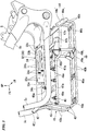
FIG. 2 is a perspective view of a fuel cell stack fixation structure seen from the left front according to the embodiment. -
FIG. 3 is a perspective view of an accommodation part support member seen from the left front according to the embodiment. -
FIG. 4 is a perspective view of a vehicle component fixation part seen from the left above according to the embodiment. -
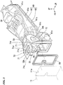
FIG. 5 is a perspective view of a seat frame seen from the left front according to the embodiment. -
FIG. 6 is a perspective view of a hydrogen tank accommodation part seen from the left front according to the embodiment. -
- 1: motorcycle (saddle-riding-type electric vehicle)
- 5: vehicle body frame
- 5b: main frame
- 5c: downward frame
- 11: fuel cell stack
- 11a: exhaust port
- 12: hydrogen tank
- 20: fuel cell stack fixation structure
- 30: cross member
- 31: upper cross member
- 31a: top wall (plate-like member, vehicle component fixation part)
- 32: lower cross member
- 34: lower plate (plate-like member)
- 40: vehicle component accommodation part
- 41: accommodation part support member
- 60: seat frame
- 63: hydrogen tank accommodation part
- 65: opening part
- 70: connection member
- Hereinafter, an embodiment of the present invention will be described with reference to the drawings. Note that, front, rear, right, and left directions and the like in the following description are the same as front, rear, right, and left directions and the like of a vehicle described below if there is no particular description. In addition, in the drawings referred to in the following description, an arrow FR which indicates the front of the vehicle, an arrow LH which indicates the left of the vehicle, and an arrow UP which indicates the upside of the vehicle are shown.
-
FIG. 1 shows a motorcycle 1 as an example of a saddle-riding-type electric vehicle. With reference toFIG. 1 , the motorcycle 1 includes: afront wheel 3 that is steered by ahandle 2; and arear wheel 4 that is driven by adrive unit 10 including an electric motor (not shown). Hereinafter, the motorcycle 1 may be simply referred to as a "vehicle". - A steering system component including the
handle 2 and thefront wheel 3 is steerably and pivotally supported by ahead pipe 5a that is formed on a front end part of avehicle body frame 5. A handle steering shaft (not shown) that is connected to thehandle 2 is inserted through thehead pipe 5a. Aswing arm 21 to which thedrive unit 10 is attached is pivotally supported swingably upward and downward around apivot shaft 22 on a rear part of thevehicle body frame 5. Arear suspension 6 is provided between a front part of theswing arm 21 and a rear part of thevehicle body frame 5. - For example, the
vehicle body frame 5 is formed by integrally joining a variety of steel materials by welding or the like. Thevehicle body frame 5 includes: a pair of right and leftmain frames 5b that extend rearward from thehead pipe 5a and that are arranged on an outer side in a vehicle width direction of afuel cell stack 11; a pair of right and left downward frames 5c that extend rearward from thehead pipe 5a and that are arranged below the pair of right and leftmain frames 5b; and a cross member 30 (refer toFIG. 2 ) that bridges a space in the vehicle width direction between at least the right and left downward frames 5c and that fixes thefuel cell stack 11. - Specifically, the right and left
main frames 5b extend rearward and downward from a middle part in a vertical direction of thehead pipe 5a and are then bent downward to extend. The rightdownward frame 5c is slightly slanted to extend downward from a lower part of thehead pipe 5a such that a lower part is positioned more rearward, is then bent rearward to extend, and is connected to a rear lower part of the rightmain frame 5b. The leftdownward frame 5c is slightly slanted to extend downward from a lower part of thehead pipe 5a such that a lower part is positioned more rearward, is then bent rearward to extend, and is connected to a rear lower part of the leftmain frame 5b. The cross member 30 (refer toFIG. 2 ) extends in the vehicle width direction so as to connect the right and leftmain frames 5b and connect the right and left downward frames 5c. - The
vehicle body frame 5 is covered by a vehicle body cover 7. The vehicle body cover 7 includes: anupper cowl 7a that covers an upper part of thevehicle body frame 5; afront side cowl 7b that covers a front side part of thevehicle body frame 5; and arear cowl 7c that covers a rear part of thevehicle body frame 5. An occupant is seated on aseat 8. Arear fender 9 covers a front upper part of therear wheel 4. - In the present embodiment, a power generation system that changes a chemical energy to an electric energy by a chemical reaction between hydrogen and oxygen is adopted. A
fuel cell stack 11 having a cuboid shape, ahydrogen tank 12 having a cylindrical shape, a hydrogen supply system (not shown), abattery 13, aninverter 14, a PDU (power drive unit) 15 that controls the flow of electricity, a VCU (voltage control unit) 16 that raises and lowers a voltage, and the like are provided on the vehicle. - The hydrogen supply system (not shown) supplies hydrogen that is stored in the
hydrogen tank 12 to thefuel cell stack 11. Thefuel cell stack 11 generates electricity by the supplied hydrogen and oxygen in external air. The electricity is used for charging thebattery 13 and is supplied to theinverter 14 and an electric component (not shown). Theinverter 14 electrically generates an AC power from a DC power that is supplied from at least one of thefuel cell stack 11 and thebattery 13. The electric motor (not shown) is driven to be rotated by the AC power that is generated by theinverter 14 and drives therear wheel 4.Hydrogen sensors - As shown in
FIG. 1 , a fuel cellstack fixation structure 20 includes: thefuel cell stack 11; and thevehicle body frame 5 that supports thefuel cell stack 11. - As shown in
FIG. 2 , thevehicle body frame 5 includes as a cross member 30: anupper cross member 31 that bridges a space in the vehicle width direction between the right and leftmain frames 5b and that fixes an upper part of the fuel cell stack 11 (refer toFIG. 1 ); and alower cross member 32 that bridges a space in the vehicle width direction between the right and left downward frames 5c and that fixes a lower part of the fuel cell stack 11 (refer toFIG. 1 ). - The
upper cross member 31 has a U shape (that is, an inverse U shape) that opens a lower part in a front view. Specifically, theupper cross member 31 includes: atop wall 31a that extends in the vehicle width direction; and a pair of right and leftside walls 31b. Theright side wall 31b extends downward from a right end in the vehicle width direction of thetop wall 31a, branches in front and rear parts, and reaches to an upper end edge of the rightmain frame 5b. Theleft side wall 31b extends downward from a left end in the vehicle width direction of thetop wall 31a, branches in front and rear parts, and reaches to an upper end edge of the leftmain frame 5b. - The
top wall 31a is a plate-like member that fixes an upper surface of the fuel cell stack 11 (refer toFIG. 1 ). A plurality of (for example, three in the present embodiment)upper fixation part 31c that fix an upper surface of the fuel cell stack 11 (refer toFIG. 1 ) are provided on thetop wall 31a. For example, in theupper fixation part 31c, the upper surface of the fuel cell stack 11 (refer toFIG. 1 ) is fastened and fixed to thetop wall 31a by a fastening member such as a bolt such that a vibration isolation member such as a rubber bush is interposed between the upper surface of thefuel cell stack 11 and thetop wall 31a. Additionally, an upper surface of thetop wall 31a functions as a vehicle component fixation part that fixes a vehicle component (for example, an electric component such as acontrol device 18 shown inFIG. 4 ). A casemember support part 31d supports acase member 50 described below (refer toFIG. 4 ). - A plurality of (for example, two in the present embodiment)
penetration holes 31h that open in a thickness direction of thetop wall 31a are formed on thetop wall 31a. Thereby, theupper cross member 31 can be made lightweight. The twopenetration holes 31h are arranged so as to avoid theupper fixation part 31c and the casemember support part 31d and to be away from each other in the vehicle width direction. - Front and rear lower end edges of the
right side wall 31b are gradually slanted rearward and downward along an upper end edge of the rightmain frame 5b. Front and rear lower end edges of theleft side wall 31b are gradually slanted rearward and downward along an upper end edge of the leftmain frame 5b. Front and rear lower end parts of theright side wall 31b are fastened and fixed to the rightmain frame 5b (specifically, a protrusion part that protrudes upward from an upper end edge of the rightmain frame 5b) by afastening member 31j such as a bolt. Front and rear lower end parts of theleft side wall 31b are fastened and fixed to the leftmain frame 5b (specifically, a protrusion part that protrudes upward from an upper end edge of the leftmain frame 5b) by afastening member 31j such as a bolt. - The
lower cross member 32 includes: a pair of front andrear connection plates lower plate 34 that is a plate-like member which fixes a lower part of the fuel cell stack 11 (refer toFIG. 1 ). - The front and
rear connection plates rear connection plates front connection plate 33a is arranged at a front lower position of the fuel cell stack 11 (refer toFIG. 1 ). On the other hand, therear connection plate 33b is arranged at a rear lower position of the fuel cell stack 11 (refer toFIG. 1 ). Thereby, it is possible to stably support the fuel cell stack 11 (refer toFIG. 1 ) in a well-balanced manner in the front-to-rear direction. - The
lower plate 34 is fixed to the front andrear connection plates front connection plate 33a and two parts of therear connection plate 33b, refer to reference numeral 33c in the drawing). For example, atfixation parts 33c, thelower plate 34 is fastened and fixed to the front andrear connection plates lower plate 34 and the front andrear connection plates - A plurality of (for example, three in the present embodiment)
lower fixation parts 34c that fix a lower surface of the fuel cell stack 11 (refer toFIG. 1 ) are provided on thelower plate 34. Thelower fixation part 34c is an axis part (male screw part) of a bolt that protrudes upward from an upper surface of thelower plate 34. For example, a plurality of (for example, three in the present embodiment) recess parts (female screw part, not shown) that is concaved upward are formed on a lower surface of the fuel cell stack 11 (refer toFIG. 1 ). Thelower plate 34 is fastened and fixed to the recess part of the lower surface of thefuel cell stack 11 by thelower fixation part 34c. - For example, the depth (vertical height) of the recess part may be larger than the vertical height of the
lower fixation part 34c. Thereby, by inserting thelower fixation part 34c to the recess part (not shown) from below while screwing thelower fixation part 34c and allowing the lower surface of the fuel cell stack 11 (refer toFIG. 1 ) to come into contact with the upper surface of thelower plate 34, it is possible to stably support the lower surface of the fuel cell stack 11 (refer toFIG. 1 ). - A plurality of (for example, two in the present embodiment)
penetration holes 34h that open in a thickness direction of thelower plate 34 are formed on thelower plate 34. Thereby, the lower cross member 32 (lower plate 34) can be made lightweight. The twopenetration holes 34h are arranged so as to avoid thefixation part 33c and thelower fixation part 34c. - In the present embodiment, the
upper cross member 31 is lighter than thelower cross member 32. For example, theupper cross member 31 is formed of a lightweight material such as aluminum, and thelower cross member 32 is formed of a heavyweight material such as iron. Additionally, the thickness of theupper cross member 31 may be thinner than the thickness of the lower cross member 32 (specifically, the thickness of each of the front andrear connection plates - A vehicle
component accommodation part 40 that accommodates a vehicle component is arranged below thedownward frame 5c. The vehiclecomponent accommodation part 40 has a box shape that opens upward and that is elongated in the front-to-rear direction. As shown inFIG. 1 , the vehiclecomponent accommodation part 40 accommodates a vehicle component such as thebattery 13, theinverter 14, thePDU 15, and theVCU 16. - As shown in
FIG. 2 , the fuel cellstack fixation structure 20 further includes an accommodationpart support member 41 that is attached to thevehicle body frame 5 and that supports the vehiclecomponent accommodation part 40. - As shown in
FIG. 3 , the accommodationpart support member 41 includes: afirst connection member 42 that bridges a space in the vehicle width direction between front lower parts of the right and left downward frames 5c; a pair of right and left support membermain bodies 43 that extend downward from thefirst connection member 42, are then bent rearward to extend and are then bent upward to extend; asecond connection member 44 that bridges a space in the vehicle width direction between rear end parts of the pair of right and left support membermain bodies 43; and a pair of right and leftthird connection members 45. The rightthird connection member 45 bridges a space in the front-to-rear direction between a front part of the right support membermain body 43 and thesecond connection member 44. The leftthird connection member 45 bridges a space in the front-to-rear direction between a front part of the left support membermain body 43 and thesecond connection member 44. - The
first connection member 42 has a straight line shape that extends in the vehicle width direction. A right end part in the vehicle width direction of thefirst connection member 42 is fastened and fixed to a front lower part (specifically, a protrusion part that protrudes inward in the vehicle width direction from a front lower part of the rightdownward frame 5c) of the rightdownward frame 5c by afastening member 42j such as a bolt. A left end part in the vehicle width direction of thefirst connection member 42 is fastened and fixed to a front lower part (specifically, a protrusion part that protrudes inward in the vehicle width direction from a front lower part of the leftdownward frame 5c) of the leftdownward frame 5c by afastening member 42j such as a bolt. - The support member
main body 43 extends along an external form of the vehicle component accommodation part 40 (refer toFIG. 2 ). Specifically, the support membermain body 43 includes: afront connection part 43a that extends rearward and downward from thefirst connection member 42, is then bent frontward and downward to extend, and is then bent rearward and downward to extend; amiddle connection part 43b that extends rearward straight from a lower end of thefront connection part 43a; and arear connection part 43c that extends upward from a rear end of themiddle connection part 43b.Connection parts middle connection parts 43b in the right and left support membermain bodies 43. - The
second connection member 44 has a U shape that opens a front upper part. Specifically, thesecond connection member 44 includes: a second connection membermain body 44a that extends in the vehicle width direction so as to bridge a space in the vehicle width direction between therear connection parts 43c; and a pair of right and leftextension parts 44b. Theright extension part 44b extends frontward and upward from a right end in the vehicle width direction of the second connection membermain body 44a. Theleft extension part 44b extends frontward and upward from a left end in the vehicle width direction of the second connection membermain body 44a. - The
third connection member 45 extends to have a crank shape in the front-to-rear direction so as to bridge a space in the front-to-rear direction between thefront connection part 43a and the second connection membermain body 44a. Specifically, thethird connection member 45 extends rearward straight from an upper part (specifically, a protrusion part that protrudes outward in the vehicle width direction from an upper part of thefront connection part 43a) of thefront connection part 43a, is then bent inward in the vehicle width direction and rearward downward to extend, and is then extend rearward straight.Connection parts third connection members 45.Brackets third connection members 45. - A bottom
wall support member 49 that supports a bottom wall of the vehicle component accommodation part 40 (refer toFIG. 2 ) is joined to thethird connection member 45. The bottomwall support member 49 includes: a bottom wall support membermain body 49a that extends to have a crank shape in the vehicle width direction and that extends frontward from a middle part in the vehicle width direction and is then bent rearward and upward to extend; and avertical extension part 49b. The rightvertical extension part 49b vertically extends so as to bridge a space in the vertical direction between a right end in the vehicle width direction of the bottom wall support membermain body 49a and the rightthird connection member 45. The leftvertical extension part 49b vertically extends so as to bridge a space in the vertical direction between a left end in the vehicle width direction of the bottom wall support membermain body 49a and the leftthird connection member 45. -
FIG. 4 shows a state in which theupper cowl 7a (refer toFIG. 1 ) and the seat 8 (refer toFIG. 1 ) are removed from the vehicle. As shown inFIG. 4 , acase member 50 that accommodates thecontrol device 18 having a cuboid shape is arranged on an upper surface of thetop wall 31a as the vehicle component fixation part. Thecase member 50 has a box shape that opens an upper part and that extends in the front-to-rear direction. - In the present embodiment, the
control device 18 is fixed to an upper surface of thetop wall 31a via a bottom wall of thecase member 50. Thecase member 50 may not be provided. That is, thecontrol device 18 may be directly fixed to the upper surface of thetop wall 31a. Thereby, a vehicle upper part can be made lightweight. - A
wiring 51 connects thehydrogen sensor 17a and the hydrogen supply system (not shown). Awiring 52 connects thehydrogen sensor 17b and the hydrogen supply system (not shown). Awiring 53 connects thehydrogen sensor 17c (refer toFIG. 1 ) and the hydrogen supply system (not shown). - The fuel cell
stack fixation structure 20 further includes aseat frame 60 that has a tube shape which extends in the front-to-rear direction and that is dividable into upper and lower parts. As shown inFIG. 5 , theseat frame 60 includes: anupper seat frame 61 which has a U shape (inverse U shape) that opens a lower part in a front view; and alower seat frame 62 which has a U shape that opens an upper part in a front view. Theupper seat frame 61 is fastened and fixed to thelower seat frame 62 by a plurality of (only five members are shown inFIG. 5 )fastening members 61c such as a bolt. Abattery accommodation part 56 accommodates a battery (not shown). - As shown in
FIG. 6 , theseat frame 60 is formed of an electrically conductive member and includes a hydrogentank accommodation part 63 that accommodates thehydrogen tank 12. Examples of the electrically conductive member include carbon. In the present embodiment, theseat frame 60 is formed of carbon. Ananchorage 64 fixes thehydrogen tank 12 and thelower seat frame 62. - A front upper part of the
lower seat frame 62 is fixed (reference numeral 62c in the drawing represents a fixation part) to the right and leftmain frames 5b (specifically, a protrusion part that protrudes upward from an upper end edge of each of the right and leftmain frames 5b, refer toFIG. 4 ). For example, in thefixation part 62c, the front upper part of thelower seat frame 62 is fastened and fixed to the protrusion part of each of the right and leftmain frames 5b by a fastening member such as a bolt. - As shown in
FIG. 5 , anopening part 65 that covers anexhaust port 11a which is provided at a rear part of thefuel cell stack 11 is provided at a front part of theseat frame 60. - A
seal member 66 having a frame shape is arranged between theexhaust port 11a of thefuel cell stack 11 and theopening part 65 of theseat frame 60. The outline of theexhaust port 11a of thefuel cell stack 11, the outline of theopening part 65 of theseat frame 60, and the external form of aseal member 66 have a homothetic shape. For example, theseal member 66 is in close contact with a rear end of theexhaust port 11a of thefuel cell stack 11 and is in close contact with an inner circumferential surface of theopening part 65 of theseat frame 60. - A
connection member 70 that connects theseat frame 60 and thevehicle body frame 5 is provided at an outer position of theopening part 65. For example, theconnection member 70 is formed of an electrically conductive member such as carbon. In the present embodiment, theconnection member 70 is formed integrally with theupper seat frame 61. - The
connection member 70 has a U shape (inverse U shape) that opens a lower part so as to cover a front upper part of theseat frame 60 from the above. Specifically, theconnection member 70 includes: a connection membermain body 71 that extends in the front-to-rear direction; and a pair of right and leftside wall parts 72. The rightside wall part 72 extends outward in the vehicle width direction and downward from a right end in the vehicle width direction of the connection membermain body 71. The leftside wall part 72 extends outward in the vehicle width direction and downward from a left end in the vehicle width direction of the connection membermain body 71. - As shown in
FIG. 4 , a front end part of the connection membermain body 71 is fixed to the upper cross member 31 (specifically, a protrusion part that protrudes rearward from a rear end of thetop wall 31a) at a plurality of parts (for example, in the present embodiment, two parts on both sides in the vehicle width direction, refer to reference numeral 71c in the drawing). For example, in thefixation part 71c, the front end part of the connection membermain body 71 is fastened and fixed to the protrusion part at the rear end of thetop wall 31a by a fastening member such as a bolt. -
Reference numeral 71d in the drawing represents a fixation part (for example, in the present embodiment, two parts on both sides in the vehicle width direction) between a rear end part of thecase member 50 and the connection membermain body 71. For example, atfixation parts 71d, the rear end part of thecase member 50 is fastened and fixed to the connection membermain body 71 by a fastening member such as a bolt such that a vibration isolation member such as a rubber bush is interposed between the rear end part of thecase member 50 and the connection membermain body 71. - As shown in
FIG. 5 ,penetration holes main body 71 are formed on the connection membermain body 71. Thepenetration hole 71h is arranged at a part, which protrudes more frontward than the openingpart 65 of theseat frame 60, of the connection membermain body 71. Thepenetration hole 71i is arranged at a more rear position than thepenetration hole 71h and at a part, which overlaps with a front upper part of theseat frame 60, of the connection membermain body 71. Thepenetration hole 71i surrounds acover 55 that covers an upper part of thehydrogen sensor 17b (refer toFIG. 4 ). - As shown in
FIG. 4 , a lower end part of the rightside wall part 72 is fixed (reference numeral 72c in the drawing represents a fixation part) to the rightmain frame 5b (specifically, a protrusion part that protrudes upward from an upper end edge of the rightmain frame 5b). A lower end part of the leftside wall part 72 is fixed (reference numeral 72c in the drawing represents a fixation part) to the leftmain frame 5b (specifically, a protrusion part that protrudes upward from an upper end edge of the leftmain frame 5b). For example, in thefixation part 72c, the lower end part of the rightside wall part 72 is fastened and fixed to the protrusion part of the rightmain frame 5b by a fastening member such as a bolt. For example, in thefixation part 72c, the lower end part of the leftside wall part 72 is fastened and fixed to the protrusion part of the leftmain frame 5b by a fastening member such as a bolt. - A
penetration hole 72h that opens in a thickness direction of the rightside wall part 72 is formed on the rightside wall part 72. Apenetration hole 72h that opens in a thickness direction of the leftside wall part 72 is formed on the leftside wall part 72. Thewirings penetration hole 72h of the leftside wall part 72. - As described above, the above embodiment includes: a
fuel cell stack 11; and avehicle body frame 5 that supports thefuel cell stack 11, wherein thevehicle body frame 5 includes: a pair of right and leftmain frames 5b that extend rearward from ahead pipe 5a and that are arranged on an outer side in a vehicle width direction of thefuel cell stack 11; a pair of right and left downward frames 5c that extend rearward from thehead pipe 5a and that are arranged below the pair of right and leftmain frames 5b; and across member 30 that bridges a space in a vehicle width direction between at least the right and left downward frames 5c and that fixes thefuel cell stack 11. - According to the configuration, the
vehicle body frame 5 includes the pair of right and leftmain frames 5b that extend rearward from thehead pipe 5a and that are arranged on the outer side in the vehicle width direction of thefuel cell stack 11, and thereby, the pair of right and leftmain frames 5b can also protect thefuel cell stack 11. Additionally, thevehicle body frame 5 includes thecross member 30 that bridges the space in the vehicle width direction between at least the right and left downward frames 5c and that fixes thefuel cell stack 11. Thereby, thecross member 30 can ensure the rigidity of thevehicle body frame 5, and it is possible to perform positioning of thefuel cell stack 11 using thecross member 30. Accordingly, it is possible to reduce the number of components. Additionally, thefuel cell stack 11 is provided at a low position of the vehicle, and therefore, it is possible to lower the position of the center of gravity and improve travel stability. - Further, in the above embodiment, the
cross member 30 includes: theupper cross member 31 that bridges the space in the vehicle width direction between the right and leftmain frames 5b and that fixes thefuel cell stack 11; and thelower cross member 32 that bridges the space in the vehicle width direction between the right and left downward frames 5c and that fixes thefuel cell stack 11, and thereby, thefuel cell stack 11 functions as a rigid member that connects the pair of right and leftmain frames 5b and the pair of right and left downward frames 5c. Therefore, it is possible to improve the rigidity of thevehicle body frame 5. - Further, in the above embodiment, the vehicle
component accommodation part 40 that is arranged below thedownward frame 5c and that accommodates the vehicle component is further provided, and thereby, the vehicle component is provided at a low position of the vehicle. Therefore, it is possible to lower the position of the center of gravity and improve travel stability. The configuration is preferably applied, for example, to a case in which the vehicle component is an electric component such as abattery 13 which is a heavy component. Additionally, the accommodationpart support member 41 that is attached to thevehicle body frame 5 and that supports the vehiclecomponent accommodation part 40 is further provided, and thereby, a plurality of vehicle components can be subassembled to the vehiclecomponent accommodation part 40 and then be assembled to thevehicle body frame 5. Therefore, it is possible to improve an assembly property. - Further, in the above embodiment, the
cross member 30 includes thetop wall 31a and thelower plate 34 as the plate-like member that fixes the upper surface or the lower surface of thefuel cell stack 11, and thereby, it is possible to further firmly fix thefuel cell stack 11. - Further, in the above embodiment, the
upper cross member 31 is lighter than thelower cross member 32, and thereby, the position of the center of gravity of the vehicle is lowered. Therefore, it is possible to improve travel stability. The configuration is preferably applied, for example, to a case in which theupper cross member 31 is formed of a lightweight material such as aluminum, and thelower cross member 32 is formed of a heavyweight material such as iron. - Further, in the above embodiment, the
upper cross member 31 includes thetop wall 31a as the vehicle component fixation part that fixes the vehicle component at the upper surface of the plate-like member, and thereby, it is possible to stably fix the vehicle component by the upper surface of the plate-like member. The configuration is preferably applied, for example, to a case in which the vehicle component is an electric component such as acontrol device 18. - Further, in the above embodiment, the
seat frame 60 that is dividable into upper and lower parts is further provided, and thereby, it is possible to use an inner space of theseat frame 60 as an accommodation space. Additionally, by making theupper seat frame 61 to be open, it is possible to easily accommodate the vehicle component to the inner space of theseat frame 60. - Further, in the above embodiment, the
seat frame 60 is formed of the electrically conductive member and includes the hydrogentank accommodation part 63 that accommodates thehydrogen tank 12, and thereby, an electric potential is sparsely distributed via themain frame 5b from theseat frame 60. Therefore, according to a grounding effect, it is possible to prevent static electricity from being generated in the vicinity of thehydrogen tank 12. - Further, in the above embodiment, the
seat frame 60 having a tube shape is further provided, and theopening part 65 that covers theexhaust port 11a which is provided at the rear part of thefuel cell stack 11 is provided at the front part of theseat frame 60, and thereby, exhaust air (besides, travel air, cooling air, and the like) which is emitted rearward from thefuel cell stack 11 can be guided smoothly to a vehicle rear part. Additionally, theconnection member 70 that connects theseat frame 60 and thevehicle body frame 5 is provided at the outer position of theopening part 65, and thereby, it is possible to improve the rigidity of thevehicle body frame 5. - The above embodiment is described using an example of the motorcycle 1 that includes the
drive unit 10 including an electric motor as an example of a saddle-riding-type electric vehicle; however, the embodiment is not limited thereto. For example, the saddle-riding-type electric vehicle may be a saddle-riding-type hybrid vehicle in which an engine is provided on the vehicle body side. - Further, the above embodiment is described using an example in which the
cross member 30 includes theupper cross member 31 and thelower cross member 32; however, the embodiment is not limited thereto. For example, the cross member may include only the lower cross member. That is, the cross member may at least bridge a space in the vehicle width direction between the right and left downward frames and fix the fuel cell stack. - Further, the above embodiment is described using an example of a cantilever swing arm in which an arm part of the
swing arm 21 is arranged only at one side (only at a left side) in the vehicle width direction of therear wheel 4; however, the embodiment is not limited thereto. For example, the swing arm may be a double support swing arm in which the arm part of the swing arm is arranged at both sides in the vehicle width direction of the rear wheel. - The present invention is not limited to the above embodiment. For example, the saddle-riding-type electric vehicle includes all vehicles on which a driver straddles a vehicle body. The saddle-riding-type electric vehicle includes not only a motorcycle (including a motorized bicycle and a scooter-type vehicle) but also a three-wheeled vehicle (including a vehicle having two front wheels and one rear wheel in addition to a vehicle having one front wheel and two rear wheels) or a four-wheeled vehicle.
- The configuration in the above embodiment is an example of the invention, and various changes such as substitution of the configuration element of the embodiment by a known configuration element can be made without departing from the scope of the invention.
- In a saddle-riding-type electric vehicle fuel cell stack fixation structure (20), a vehicle body frame (5) includes: a pair of right and left main frames (5b) that extend rearward from a head pipe (5a) and that are arranged on an outer side in a vehicle width direction of a fuel cell stack; a pair of right and left downward frames (5c) that extend rearward from the head pipe (5a) and that are arranged below the pair of right and left main frames (5b); and a cross member (30) that bridges a space in a vehicle width direction between at least the right and left downward frames (5c) and that fixes the fuel cell stack.
Claims (9)
- A saddle-riding-type electric vehicle fuel cell stack fixation structure, comprising:a fuel cell stack; anda vehicle body frame that supports the fuel cell stack, whereinthe vehicle body frame includes:a pair of right and left main frames that extend rearward from a head pipe and that are arranged on an outer side in a vehicle width direction of the fuel cell stack;a pair of right and left downward frames that extend rearward from the head pipe and that are arranged below the pair of right and left main frames; anda cross member that bridges a space in a vehicle width direction between at least the right and left downward frames and that fixes the fuel cell stack.
- The saddle-riding-type electric vehicle fuel cell stack fixation structure according to claim 1, wherein
the cross member includes:an upper cross member that bridges a space in a vehicle width direction between the right and left main frames and that fixes the fuel cell stack; anda lower cross member that bridges a space in a vehicle width direction between the right and left downward frames and that fixes the fuel cell stack. - The saddle-riding-type electric vehicle fuel cell stack fixation structure according to claim 1 or 2, further comprising:a vehicle component accommodation part that is arranged below the downward frame and that accommodates a vehicle component; andan accommodation part support member that is attached to the vehicle body frame and that supports the vehicle component accommodation part.
- The saddle-riding-type electric vehicle fuel cell stack fixation structure according to any one of claims 1 to 3, wherein
the cross member includes a plate-like member that fixes an upper surface or a lower surface of the fuel cell stack. - The saddle-riding-type electric vehicle fuel cell stack fixation structure according to any one of claims 1 to 4, wherein
the cross member includes:an upper cross member that bridges a space in a vehicle width direction between the right and left main frames; anda lower cross member that bridges a space in a vehicle width direction between the right and left downward frames, andthe upper cross member is lighter than the lower cross member. - The saddle-riding-type electric vehicle fuel cell stack fixation structure according to any one of claims 1 to 5, wherein
the cross member includes an upper cross member that bridges a space in a vehicle width direction between the right and left main frames, and
the upper cross member includes a vehicle component fixation part that fixes a vehicle component at an upper surface of a plate-like member. - The saddle-riding-type electric vehicle fuel cell stack fixation structure according to any one of claims 1 to 6, further comprising
a seat frame that is dividable into upper and lower parts. - The saddle-riding-type electric vehicle fuel cell stack fixation structure according to claim 7, wherein
the seat frame is formed of an electrically conductive member and includes a hydrogen tank accommodation part that accommodates a hydrogen tank. - The saddle-riding-type electric vehicle fuel cell stack fixation structure according to any one of claims 1 to 8, further comprising
a seat frame having a tube shape, wherein
an opening part that covers an exhaust port which is provided at a rear part of the fuel cell stack is provided at a front part of the seat frame, and
a connection member that connects the seat frame and the vehicle body frame is provided at an outer position of the opening part.
Applications Claiming Priority (1)
| Application Number | Priority Date | Filing Date | Title |
|---|---|---|---|
| JP2016191828A JP6433031B2 (en) | 2016-09-29 | 2016-09-29 | Fuel cell stack fixing structure for saddle-ride type electric vehicle |
Publications (2)
| Publication Number | Publication Date |
|---|---|
| EP3301008A1 true EP3301008A1 (en) | 2018-04-04 |
| EP3301008B1 EP3301008B1 (en) | 2020-02-19 |
Family
ID=59966644
Family Applications (1)
| Application Number | Title | Priority Date | Filing Date |
|---|---|---|---|
| EP17192903.7A Active EP3301008B1 (en) | 2016-09-29 | 2017-09-25 | Saddle-riding-type electric vehicle fuel cell stack fixation structure |
Country Status (4)
| Country | Link |
|---|---|
| US (1) | US10479434B2 (en) |
| EP (1) | EP3301008B1 (en) |
| JP (1) | JP6433031B2 (en) |
| CN (1) | CN107878649B (en) |
Cited By (1)
| Publication number | Priority date | Publication date | Assignee | Title |
|---|---|---|---|---|
| TWI764669B (en) * | 2021-04-13 | 2022-05-11 | 光陽工業股份有限公司 | Battery positioning device for electric vehicle |
Families Citing this family (5)
| Publication number | Priority date | Publication date | Assignee | Title |
|---|---|---|---|---|
| US20170282749A1 (en) * | 2016-03-31 | 2017-10-05 | Honda Motor Co., Ltd. | Saddle-ride type vehicle |
| US10843759B2 (en) * | 2017-10-25 | 2020-11-24 | Yamaha Hatsudoki Kabushiki Kaisha | Vehicle |
| JP6997692B2 (en) | 2018-09-28 | 2022-01-18 | 本田技研工業株式会社 | Saddle-type vehicle |
| JP7074042B2 (en) * | 2018-12-11 | 2022-05-24 | トヨタ自動車株式会社 | Stack frame |
| TW202045379A (en) * | 2019-06-06 | 2020-12-16 | 品睿綠能科技股份有限公司 | Battery compartment structure of straddle-type electric motorcycle capable of achieving the objective of integrating the battery compartment and the frame structure of the electric motorcycle |
Citations (5)
| Publication number | Priority date | Publication date | Assignee | Title |
|---|---|---|---|---|
| JP2009078624A (en) | 2007-09-25 | 2009-04-16 | Suzuki Motor Corp | Fuel cell vehicle |
| EP2168863A1 (en) * | 2008-09-30 | 2010-03-31 | Honda Motor Co., Ltd | Saddle-ride electric vehicle |
| US20140353061A1 (en) * | 2013-06-04 | 2014-12-04 | Suzuki Motor Corporation | Fuel-cell vehicle |
| US20140367183A1 (en) * | 2011-10-28 | 2014-12-18 | Kawasaki Jukogyo Kabushiki Kaisha | Straddle Electric Vehicle |
| EP3225522A2 (en) * | 2016-03-31 | 2017-10-04 | Honda Motor Co., Ltd. | Saddle-ride type vehicle |
Family Cites Families (26)
| Publication number | Priority date | Publication date | Assignee | Title |
|---|---|---|---|---|
| JPS56146016A (en) * | 1980-04-15 | 1981-11-13 | Honda Motor Co Ltd | Supercharger device in autobicycle |
| JP2724748B2 (en) * | 1989-05-13 | 1998-03-09 | 本田技研工業株式会社 | Motorcycle |
| JP2003176762A (en) * | 2001-09-27 | 2003-06-27 | Yamaha Motor Co Ltd | Fuel hose mounting structure for fuel injection engine |
| MY142590A (en) * | 2004-02-06 | 2010-12-15 | Honda Motor Co Ltd | A fuel injection system for a saddle ride type four-wheel vehicle |
| JP4498856B2 (en) * | 2004-08-19 | 2010-07-07 | 本田技研工業株式会社 | Hydrogen filling port arrangement structure in fuel cell vehicle |
| JP2006056355A (en) * | 2004-08-19 | 2006-03-02 | Honda Motor Co Ltd | Exhaust structure in fuel cell vehicle |
| DE602006002154D1 (en) * | 2005-04-04 | 2008-09-25 | Honda Motor Co Ltd | Motorcycle with fuel cell |
| JP4771410B2 (en) * | 2005-10-25 | 2011-09-14 | 本田技研工業株式会社 | Fuel cell motorcycle |
| JP4454574B2 (en) * | 2005-11-30 | 2010-04-21 | 本田技研工業株式会社 | Cooling device for fuel cell vehicle |
| JP2008100574A (en) * | 2006-10-18 | 2008-05-01 | Yamaha Motor Co Ltd | Motorcycle |
| JP5014858B2 (en) * | 2007-03-28 | 2012-08-29 | 本田技研工業株式会社 | Body frame structure |
| JP5035886B2 (en) * | 2007-03-30 | 2012-09-26 | 本田技研工業株式会社 | Saddle type fuel cell vehicle |
| JP5387132B2 (en) * | 2009-05-20 | 2014-01-15 | スズキ株式会社 | Fuel tank support structure for scooter type fuel cell motorcycle |
| JP5417992B2 (en) | 2009-05-27 | 2014-02-19 | スズキ株式会社 | Fuel cell vehicle |
| JP5648421B2 (en) * | 2010-10-26 | 2015-01-07 | マツダ株式会社 | Battery mounting structure for electric vehicles |
| US8973697B2 (en) * | 2010-12-24 | 2015-03-10 | Kawasaki Jukogyo Kabushiki Kaisha | Saddle-type electric vehicle |
| WO2013061387A1 (en) * | 2011-10-28 | 2013-05-02 | 川崎重工業株式会社 | Saddle-type electric vehicle |
| JP5600669B2 (en) * | 2011-12-28 | 2014-10-01 | 本田技研工業株式会社 | Body structure of saddle riding type electric vehicle |
| CN104114396B (en) * | 2012-02-07 | 2016-08-31 | 本田技研工业株式会社 | Fuel-cell vehicle |
| CN104321244B (en) * | 2012-05-28 | 2017-03-08 | 本田技研工业株式会社 | Straddle-type vehicle |
| JP5926653B2 (en) * | 2012-08-28 | 2016-05-25 | 本田技研工業株式会社 | Storage structure of saddle-ride type vehicle |
| JP6197431B2 (en) * | 2013-07-19 | 2017-09-20 | スズキ株式会社 | Motorcycle |
| JP6191381B2 (en) * | 2013-10-17 | 2017-09-06 | スズキ株式会社 | Fuel cell motorcycle |
| JP2016088160A (en) * | 2014-10-30 | 2016-05-23 | スズキ株式会社 | Fuel cell two-wheeled vehicle |
| JP6561769B2 (en) * | 2015-10-27 | 2019-08-21 | スズキ株式会社 | Exhaust duct structure for fuel cell vehicles |
| JP6463318B2 (en) * | 2016-03-31 | 2019-01-30 | 本田技研工業株式会社 | Saddle riding |
-
2016
- 2016-09-29 JP JP2016191828A patent/JP6433031B2/en active Active
-
2017
- 2017-09-15 US US15/706,344 patent/US10479434B2/en active Active
- 2017-09-22 CN CN201710870162.4A patent/CN107878649B/en active Active
- 2017-09-25 EP EP17192903.7A patent/EP3301008B1/en active Active
Patent Citations (5)
| Publication number | Priority date | Publication date | Assignee | Title |
|---|---|---|---|---|
| JP2009078624A (en) | 2007-09-25 | 2009-04-16 | Suzuki Motor Corp | Fuel cell vehicle |
| EP2168863A1 (en) * | 2008-09-30 | 2010-03-31 | Honda Motor Co., Ltd | Saddle-ride electric vehicle |
| US20140367183A1 (en) * | 2011-10-28 | 2014-12-18 | Kawasaki Jukogyo Kabushiki Kaisha | Straddle Electric Vehicle |
| US20140353061A1 (en) * | 2013-06-04 | 2014-12-04 | Suzuki Motor Corporation | Fuel-cell vehicle |
| EP3225522A2 (en) * | 2016-03-31 | 2017-10-04 | Honda Motor Co., Ltd. | Saddle-ride type vehicle |
Cited By (1)
| Publication number | Priority date | Publication date | Assignee | Title |
|---|---|---|---|---|
| TWI764669B (en) * | 2021-04-13 | 2022-05-11 | 光陽工業股份有限公司 | Battery positioning device for electric vehicle |
Also Published As
| Publication number | Publication date |
|---|---|
| US20180086408A1 (en) | 2018-03-29 |
| US10479434B2 (en) | 2019-11-19 |
| EP3301008B1 (en) | 2020-02-19 |
| CN107878649A (en) | 2018-04-06 |
| JP2018052353A (en) | 2018-04-05 |
| CN107878649B (en) | 2020-10-23 |
| JP6433031B2 (en) | 2018-12-05 |
Similar Documents
| Publication | Publication Date | Title |
|---|---|---|
| EP3301008B1 (en) | Saddle-riding-type electric vehicle fuel cell stack fixation structure | |
| US7614473B2 (en) | Vehicle body structure | |
| EP2530000B1 (en) | Electric motorcycle and controller unit | |
| JP5879173B2 (en) | Electric saddle riding type vehicle | |
| US20130233634A1 (en) | Electric Motorcycle | |
| JP5443152B2 (en) | Electric motorcycle | |
| CN107878647B (en) | Saddle-ride type vehicle | |
| WO2020044792A1 (en) | Battery pack arrangement structure | |
| TWI462372B (en) | Battery unit | |
| JP2006176105A (en) | Fuel cell vehicle | |
| JP5588825B2 (en) | Electric motorcycle | |
| US9168819B2 (en) | Electricity-storage device arrangement structure of vehicle | |
| JP2011143857A (en) | Vehicle | |
| US20180037291A1 (en) | Swing arm structure for saddle riding electric vehicle | |
| JP5764644B2 (en) | Electric motorcycle | |
| JP2020196403A (en) | Saddle-riding vehicle | |
| JP2006315656A (en) | Fuel tank mounting structure of motorcycle | |
| JP6696293B2 (en) | Electric motorcycle | |
| JP2023116134A (en) | Electric straddle-type vehicle | |
| JP4844315B2 (en) | Small electric vehicle with fuel cell | |
| JP5470107B2 (en) | vehicle | |
| CN112770964B (en) | Saddle-ride type electric vehicle | |
| JP2005319865A (en) | Motorcycle | |
| JP6180265B2 (en) | Vehicle with electric drive device | |
| JPH11206821A (en) | Motor vehicle |
Legal Events
| Date | Code | Title | Description |
|---|---|---|---|
| PUAI | Public reference made under article 153(3) epc to a published international application that has entered the european phase |
Free format text: ORIGINAL CODE: 0009012 |
|
| STAA | Information on the status of an ep patent application or granted ep patent |
Free format text: STATUS: REQUEST FOR EXAMINATION WAS MADE |
|
| 17P | Request for examination filed |
Effective date: 20170925 |
|
| AK | Designated contracting states |
Kind code of ref document: A1 Designated state(s): AL AT BE BG CH CY CZ DE DK EE ES FI FR GB GR HR HU IE IS IT LI LT LU LV MC MK MT NL NO PL PT RO RS SE SI SK SM TR |
|
| AX | Request for extension of the european patent |
Extension state: BA ME |
|
| STAA | Information on the status of an ep patent application or granted ep patent |
Free format text: STATUS: EXAMINATION IS IN PROGRESS |
|
| 17Q | First examination report despatched |
Effective date: 20190124 |
|
| GRAP | Despatch of communication of intention to grant a patent |
Free format text: ORIGINAL CODE: EPIDOSNIGR1 |
|
| STAA | Information on the status of an ep patent application or granted ep patent |
Free format text: STATUS: GRANT OF PATENT IS INTENDED |
|
| INTG | Intention to grant announced |
Effective date: 20190808 |
|
| GRAS | Grant fee paid |
Free format text: ORIGINAL CODE: EPIDOSNIGR3 |
|
| GRAJ | Information related to disapproval of communication of intention to grant by the applicant or resumption of examination proceedings by the epo deleted |
Free format text: ORIGINAL CODE: EPIDOSDIGR1 |
|
| GRAL | Information related to payment of fee for publishing/printing deleted |
Free format text: ORIGINAL CODE: EPIDOSDIGR3 |
|
| STAA | Information on the status of an ep patent application or granted ep patent |
Free format text: STATUS: EXAMINATION IS IN PROGRESS |
|
| GRAR | Information related to intention to grant a patent recorded |
Free format text: ORIGINAL CODE: EPIDOSNIGR71 |
|
| STAA | Information on the status of an ep patent application or granted ep patent |
Free format text: STATUS: GRANT OF PATENT IS INTENDED |
|
| GRAA | (expected) grant |
Free format text: ORIGINAL CODE: 0009210 |
|
| STAA | Information on the status of an ep patent application or granted ep patent |
Free format text: STATUS: THE PATENT HAS BEEN GRANTED |
|
| INTC | Intention to grant announced (deleted) | ||
| AK | Designated contracting states |
Kind code of ref document: B1 Designated state(s): AL AT BE BG CH CY CZ DE DK EE ES FI FR GB GR HR HU IE IS IT LI LT LU LV MC MK MT NL NO PL PT RO RS SE SI SK SM TR |
|
| INTG | Intention to grant announced |
Effective date: 20200113 |
|
| REG | Reference to a national code |
Ref country code: CH Ref legal event code: EP |
|
| REG | Reference to a national code |
Ref country code: DE Ref legal event code: R096 Ref document number: 602017011901 Country of ref document: DE |
|
| REG | Reference to a national code |
Ref country code: AT Ref legal event code: REF Ref document number: 1234663 Country of ref document: AT Kind code of ref document: T Effective date: 20200315 |
|
| REG | Reference to a national code |
Ref country code: IE Ref legal event code: FG4D |
|
| REG | Reference to a national code |
Ref country code: NL Ref legal event code: MP Effective date: 20200219 |
|
| PG25 | Lapsed in a contracting state [announced via postgrant information from national office to epo] |
Ref country code: RS Free format text: LAPSE BECAUSE OF FAILURE TO SUBMIT A TRANSLATION OF THE DESCRIPTION OR TO PAY THE FEE WITHIN THE PRESCRIBED TIME-LIMIT Effective date: 20200219 Ref country code: NO Free format text: LAPSE BECAUSE OF FAILURE TO SUBMIT A TRANSLATION OF THE DESCRIPTION OR TO PAY THE FEE WITHIN THE PRESCRIBED TIME-LIMIT Effective date: 20200519 Ref country code: FI Free format text: LAPSE BECAUSE OF FAILURE TO SUBMIT A TRANSLATION OF THE DESCRIPTION OR TO PAY THE FEE WITHIN THE PRESCRIBED TIME-LIMIT Effective date: 20200219 |
|
| REG | Reference to a national code |
Ref country code: LT Ref legal event code: MG4D |
|
| PG25 | Lapsed in a contracting state [announced via postgrant information from national office to epo] |
Ref country code: IS Free format text: LAPSE BECAUSE OF FAILURE TO SUBMIT A TRANSLATION OF THE DESCRIPTION OR TO PAY THE FEE WITHIN THE PRESCRIBED TIME-LIMIT Effective date: 20200619 Ref country code: GR Free format text: LAPSE BECAUSE OF FAILURE TO SUBMIT A TRANSLATION OF THE DESCRIPTION OR TO PAY THE FEE WITHIN THE PRESCRIBED TIME-LIMIT Effective date: 20200520 Ref country code: LV Free format text: LAPSE BECAUSE OF FAILURE TO SUBMIT A TRANSLATION OF THE DESCRIPTION OR TO PAY THE FEE WITHIN THE PRESCRIBED TIME-LIMIT Effective date: 20200219 Ref country code: SE Free format text: LAPSE BECAUSE OF FAILURE TO SUBMIT A TRANSLATION OF THE DESCRIPTION OR TO PAY THE FEE WITHIN THE PRESCRIBED TIME-LIMIT Effective date: 20200219 Ref country code: HR Free format text: LAPSE BECAUSE OF FAILURE TO SUBMIT A TRANSLATION OF THE DESCRIPTION OR TO PAY THE FEE WITHIN THE PRESCRIBED TIME-LIMIT Effective date: 20200219 Ref country code: BG Free format text: LAPSE BECAUSE OF FAILURE TO SUBMIT A TRANSLATION OF THE DESCRIPTION OR TO PAY THE FEE WITHIN THE PRESCRIBED TIME-LIMIT Effective date: 20200519 |
|
| PG25 | Lapsed in a contracting state [announced via postgrant information from national office to epo] |
Ref country code: NL Free format text: LAPSE BECAUSE OF FAILURE TO SUBMIT A TRANSLATION OF THE DESCRIPTION OR TO PAY THE FEE WITHIN THE PRESCRIBED TIME-LIMIT Effective date: 20200219 |
|
| PG25 | Lapsed in a contracting state [announced via postgrant information from national office to epo] |
Ref country code: DK Free format text: LAPSE BECAUSE OF FAILURE TO SUBMIT A TRANSLATION OF THE DESCRIPTION OR TO PAY THE FEE WITHIN THE PRESCRIBED TIME-LIMIT Effective date: 20200219 Ref country code: LT Free format text: LAPSE BECAUSE OF FAILURE TO SUBMIT A TRANSLATION OF THE DESCRIPTION OR TO PAY THE FEE WITHIN THE PRESCRIBED TIME-LIMIT Effective date: 20200219 Ref country code: ES Free format text: LAPSE BECAUSE OF FAILURE TO SUBMIT A TRANSLATION OF THE DESCRIPTION OR TO PAY THE FEE WITHIN THE PRESCRIBED TIME-LIMIT Effective date: 20200219 Ref country code: SM Free format text: LAPSE BECAUSE OF FAILURE TO SUBMIT A TRANSLATION OF THE DESCRIPTION OR TO PAY THE FEE WITHIN THE PRESCRIBED TIME-LIMIT Effective date: 20200219 Ref country code: EE Free format text: LAPSE BECAUSE OF FAILURE TO SUBMIT A TRANSLATION OF THE DESCRIPTION OR TO PAY THE FEE WITHIN THE PRESCRIBED TIME-LIMIT Effective date: 20200219 Ref country code: CZ Free format text: LAPSE BECAUSE OF FAILURE TO SUBMIT A TRANSLATION OF THE DESCRIPTION OR TO PAY THE FEE WITHIN THE PRESCRIBED TIME-LIMIT Effective date: 20200219 Ref country code: RO Free format text: LAPSE BECAUSE OF FAILURE TO SUBMIT A TRANSLATION OF THE DESCRIPTION OR TO PAY THE FEE WITHIN THE PRESCRIBED TIME-LIMIT Effective date: 20200219 Ref country code: PT Free format text: LAPSE BECAUSE OF FAILURE TO SUBMIT A TRANSLATION OF THE DESCRIPTION OR TO PAY THE FEE WITHIN THE PRESCRIBED TIME-LIMIT Effective date: 20200712 Ref country code: SK Free format text: LAPSE BECAUSE OF FAILURE TO SUBMIT A TRANSLATION OF THE DESCRIPTION OR TO PAY THE FEE WITHIN THE PRESCRIBED TIME-LIMIT Effective date: 20200219 |
|
| REG | Reference to a national code |
Ref country code: AT Ref legal event code: MK05 Ref document number: 1234663 Country of ref document: AT Kind code of ref document: T Effective date: 20200219 |
|
| REG | Reference to a national code |
Ref country code: DE Ref legal event code: R097 Ref document number: 602017011901 Country of ref document: DE |
|
| PLBE | No opposition filed within time limit |
Free format text: ORIGINAL CODE: 0009261 |
|
| STAA | Information on the status of an ep patent application or granted ep patent |
Free format text: STATUS: NO OPPOSITION FILED WITHIN TIME LIMIT |
|
| 26N | No opposition filed |
Effective date: 20201120 |
|
| PG25 | Lapsed in a contracting state [announced via postgrant information from national office to epo] |
Ref country code: IT Free format text: LAPSE BECAUSE OF FAILURE TO SUBMIT A TRANSLATION OF THE DESCRIPTION OR TO PAY THE FEE WITHIN THE PRESCRIBED TIME-LIMIT Effective date: 20200219 Ref country code: AT Free format text: LAPSE BECAUSE OF FAILURE TO SUBMIT A TRANSLATION OF THE DESCRIPTION OR TO PAY THE FEE WITHIN THE PRESCRIBED TIME-LIMIT Effective date: 20200219 |
|
| PG25 | Lapsed in a contracting state [announced via postgrant information from national office to epo] |
Ref country code: PL Free format text: LAPSE BECAUSE OF FAILURE TO SUBMIT A TRANSLATION OF THE DESCRIPTION OR TO PAY THE FEE WITHIN THE PRESCRIBED TIME-LIMIT Effective date: 20200219 Ref country code: SI Free format text: LAPSE BECAUSE OF FAILURE TO SUBMIT A TRANSLATION OF THE DESCRIPTION OR TO PAY THE FEE WITHIN THE PRESCRIBED TIME-LIMIT Effective date: 20200219 |
|
| REG | Reference to a national code |
Ref country code: CH Ref legal event code: PL |
|
| REG | Reference to a national code |
Ref country code: BE Ref legal event code: MM Effective date: 20200930 |
|
| PG25 | Lapsed in a contracting state [announced via postgrant information from national office to epo] |
Ref country code: LU Free format text: LAPSE BECAUSE OF NON-PAYMENT OF DUE FEES Effective date: 20200925 |
|
| PG25 | Lapsed in a contracting state [announced via postgrant information from national office to epo] |
Ref country code: FR Free format text: LAPSE BECAUSE OF NON-PAYMENT OF DUE FEES Effective date: 20200930 |
|
| REG | Reference to a national code |
Ref country code: DE Ref legal event code: R084 Ref document number: 602017011901 Country of ref document: DE |
|
| PG25 | Lapsed in a contracting state [announced via postgrant information from national office to epo] |
Ref country code: LI Free format text: LAPSE BECAUSE OF NON-PAYMENT OF DUE FEES Effective date: 20200930 Ref country code: IE Free format text: LAPSE BECAUSE OF NON-PAYMENT OF DUE FEES Effective date: 20200925 Ref country code: BE Free format text: LAPSE BECAUSE OF NON-PAYMENT OF DUE FEES Effective date: 20200930 Ref country code: CH Free format text: LAPSE BECAUSE OF NON-PAYMENT OF DUE FEES Effective date: 20200930 |
|
| GBPC | Gb: european patent ceased through non-payment of renewal fee |
Effective date: 20210925 |
|
| PG25 | Lapsed in a contracting state [announced via postgrant information from national office to epo] |
Ref country code: TR Free format text: LAPSE BECAUSE OF FAILURE TO SUBMIT A TRANSLATION OF THE DESCRIPTION OR TO PAY THE FEE WITHIN THE PRESCRIBED TIME-LIMIT Effective date: 20200219 Ref country code: MT Free format text: LAPSE BECAUSE OF FAILURE TO SUBMIT A TRANSLATION OF THE DESCRIPTION OR TO PAY THE FEE WITHIN THE PRESCRIBED TIME-LIMIT Effective date: 20200219 Ref country code: CY Free format text: LAPSE BECAUSE OF FAILURE TO SUBMIT A TRANSLATION OF THE DESCRIPTION OR TO PAY THE FEE WITHIN THE PRESCRIBED TIME-LIMIT Effective date: 20200219 |
|
| PG25 | Lapsed in a contracting state [announced via postgrant information from national office to epo] |
Ref country code: MK Free format text: LAPSE BECAUSE OF FAILURE TO SUBMIT A TRANSLATION OF THE DESCRIPTION OR TO PAY THE FEE WITHIN THE PRESCRIBED TIME-LIMIT Effective date: 20200219 Ref country code: MC Free format text: LAPSE BECAUSE OF FAILURE TO SUBMIT A TRANSLATION OF THE DESCRIPTION OR TO PAY THE FEE WITHIN THE PRESCRIBED TIME-LIMIT Effective date: 20200219 Ref country code: AL Free format text: LAPSE BECAUSE OF FAILURE TO SUBMIT A TRANSLATION OF THE DESCRIPTION OR TO PAY THE FEE WITHIN THE PRESCRIBED TIME-LIMIT Effective date: 20200219 |
|
| PG25 | Lapsed in a contracting state [announced via postgrant information from national office to epo] |
Ref country code: GB Free format text: LAPSE BECAUSE OF NON-PAYMENT OF DUE FEES Effective date: 20210925 |
|
| PGFP | Annual fee paid to national office [announced via postgrant information from national office to epo] |
Ref country code: DE Payment date: 20230802 Year of fee payment: 7 |