EP3225522A2 - Saddle-ride type vehicle - Google Patents
Saddle-ride type vehicle Download PDFInfo
- Publication number
- EP3225522A2 EP3225522A2 EP17163257.3A EP17163257A EP3225522A2 EP 3225522 A2 EP3225522 A2 EP 3225522A2 EP 17163257 A EP17163257 A EP 17163257A EP 3225522 A2 EP3225522 A2 EP 3225522A2
- Authority
- EP
- European Patent Office
- Prior art keywords
- fuel cell
- frame
- cell unit
- seat frame
- saddle
- Prior art date
- Legal status (The legal status is an assumption and is not a legal conclusion. Google has not performed a legal analysis and makes no representation as to the accuracy of the status listed.)
- Granted
Links
- 239000000446 fuel Substances 0.000 claims abstract description 73
- 239000007789 gas Substances 0.000 claims abstract description 13
- 238000001816 cooling Methods 0.000 claims abstract description 10
- QVGXLLKOCUKJST-UHFFFAOYSA-N atomic oxygen Chemical compound [O] QVGXLLKOCUKJST-UHFFFAOYSA-N 0.000 claims abstract description 6
- 239000001301 oxygen Substances 0.000 claims abstract description 6
- 229910052760 oxygen Inorganic materials 0.000 claims abstract description 6
- 239000002828 fuel tank Substances 0.000 claims description 24
- 239000001257 hydrogen Substances 0.000 claims description 14
- 229910052739 hydrogen Inorganic materials 0.000 claims description 14
- UFHFLCQGNIYNRP-UHFFFAOYSA-N Hydrogen Chemical compound [H][H] UFHFLCQGNIYNRP-UHFFFAOYSA-N 0.000 claims description 11
- 238000007789 sealing Methods 0.000 claims description 7
- 238000000638 solvent extraction Methods 0.000 claims description 4
- 238000009423 ventilation Methods 0.000 abstract description 10
- 230000000694 effects Effects 0.000 description 4
- 150000002431 hydrogen Chemical class 0.000 description 3
- 238000006243 chemical reaction Methods 0.000 description 2
- 230000008878 coupling Effects 0.000 description 2
- 238000010168 coupling process Methods 0.000 description 2
- 238000005859 coupling reaction Methods 0.000 description 2
- 238000012423 maintenance Methods 0.000 description 2
- 241001247986 Calotropis procera Species 0.000 description 1
- OKTJSMMVPCPJKN-UHFFFAOYSA-N Carbon Chemical compound [C] OKTJSMMVPCPJKN-UHFFFAOYSA-N 0.000 description 1
- 230000005540 biological transmission Effects 0.000 description 1
- 229910052799 carbon Inorganic materials 0.000 description 1
- 239000004020 conductor Substances 0.000 description 1
- 238000001514 detection method Methods 0.000 description 1
- 238000010586 diagram Methods 0.000 description 1
- 230000005611 electricity Effects 0.000 description 1
- 239000000463 material Substances 0.000 description 1
- 239000002184 metal Substances 0.000 description 1
- 238000005192 partition Methods 0.000 description 1
- 230000003068 static effect Effects 0.000 description 1
Images


Classifications
-
- B—PERFORMING OPERATIONS; TRANSPORTING
- B60—VEHICLES IN GENERAL
- B60L—PROPULSION OF ELECTRICALLY-PROPELLED VEHICLES; SUPPLYING ELECTRIC POWER FOR AUXILIARY EQUIPMENT OF ELECTRICALLY-PROPELLED VEHICLES; ELECTRODYNAMIC BRAKE SYSTEMS FOR VEHICLES IN GENERAL; MAGNETIC SUSPENSION OR LEVITATION FOR VEHICLES; MONITORING OPERATING VARIABLES OF ELECTRICALLY-PROPELLED VEHICLES; ELECTRIC SAFETY DEVICES FOR ELECTRICALLY-PROPELLED VEHICLES
- B60L50/00—Electric propulsion with power supplied within the vehicle
- B60L50/50—Electric propulsion with power supplied within the vehicle using propulsion power supplied by batteries or fuel cells
- B60L50/70—Electric propulsion with power supplied within the vehicle using propulsion power supplied by batteries or fuel cells using power supplied by fuel cells
- B60L50/71—Arrangement of fuel cells within vehicles specially adapted for electric vehicles
-
- B—PERFORMING OPERATIONS; TRANSPORTING
- B60—VEHICLES IN GENERAL
- B60K—ARRANGEMENT OR MOUNTING OF PROPULSION UNITS OR OF TRANSMISSIONS IN VEHICLES; ARRANGEMENT OR MOUNTING OF PLURAL DIVERSE PRIME-MOVERS IN VEHICLES; AUXILIARY DRIVES FOR VEHICLES; INSTRUMENTATION OR DASHBOARDS FOR VEHICLES; ARRANGEMENTS IN CONNECTION WITH COOLING, AIR INTAKE, GAS EXHAUST OR FUEL SUPPLY OF PROPULSION UNITS IN VEHICLES
- B60K13/00—Arrangement in connection with combustion air intake or gas exhaust of propulsion units
- B60K13/04—Arrangement in connection with combustion air intake or gas exhaust of propulsion units concerning exhaust
-
- B—PERFORMING OPERATIONS; TRANSPORTING
- B60—VEHICLES IN GENERAL
- B60L—PROPULSION OF ELECTRICALLY-PROPELLED VEHICLES; SUPPLYING ELECTRIC POWER FOR AUXILIARY EQUIPMENT OF ELECTRICALLY-PROPELLED VEHICLES; ELECTRODYNAMIC BRAKE SYSTEMS FOR VEHICLES IN GENERAL; MAGNETIC SUSPENSION OR LEVITATION FOR VEHICLES; MONITORING OPERATING VARIABLES OF ELECTRICALLY-PROPELLED VEHICLES; ELECTRIC SAFETY DEVICES FOR ELECTRICALLY-PROPELLED VEHICLES
- B60L58/00—Methods or circuit arrangements for monitoring or controlling batteries or fuel cells, specially adapted for electric vehicles
- B60L58/30—Methods or circuit arrangements for monitoring or controlling batteries or fuel cells, specially adapted for electric vehicles for monitoring or controlling fuel cells
- B60L58/32—Methods or circuit arrangements for monitoring or controlling batteries or fuel cells, specially adapted for electric vehicles for monitoring or controlling fuel cells for controlling the temperature of fuel cells, e.g. by controlling the electric load
- B60L58/33—Methods or circuit arrangements for monitoring or controlling batteries or fuel cells, specially adapted for electric vehicles for monitoring or controlling fuel cells for controlling the temperature of fuel cells, e.g. by controlling the electric load by cooling
-
- B—PERFORMING OPERATIONS; TRANSPORTING
- B62—LAND VEHICLES FOR TRAVELLING OTHERWISE THAN ON RAILS
- B62J—CYCLE SADDLES OR SEATS; AUXILIARY DEVICES OR ACCESSORIES SPECIALLY ADAPTED TO CYCLES AND NOT OTHERWISE PROVIDED FOR, e.g. ARTICLE CARRIERS OR CYCLE PROTECTORS
- B62J1/00—Saddles or other seats for cycles; Arrangement thereof; Component parts
- B62J1/08—Frames for saddles; Connections between saddle frames and seat pillars; Seat pillars
-
- B—PERFORMING OPERATIONS; TRANSPORTING
- B62—LAND VEHICLES FOR TRAVELLING OTHERWISE THAN ON RAILS
- B62J—CYCLE SADDLES OR SEATS; AUXILIARY DEVICES OR ACCESSORIES SPECIALLY ADAPTED TO CYCLES AND NOT OTHERWISE PROVIDED FOR, e.g. ARTICLE CARRIERS OR CYCLE PROTECTORS
- B62J35/00—Fuel tanks specially adapted for motorcycles or engine-assisted cycles; Arrangements thereof
-
- B—PERFORMING OPERATIONS; TRANSPORTING
- B62—LAND VEHICLES FOR TRAVELLING OTHERWISE THAN ON RAILS
- B62K—CYCLES; CYCLE FRAMES; CYCLE STEERING DEVICES; RIDER-OPERATED TERMINAL CONTROLS SPECIALLY ADAPTED FOR CYCLES; CYCLE AXLE SUSPENSIONS; CYCLE SIDE-CARS, FORECARS, OR THE LIKE
- B62K11/00—Motorcycles, engine-assisted cycles or motor scooters with one or two wheels
- B62K11/02—Frames
- B62K11/04—Frames characterised by the engine being between front and rear wheels
-
- B—PERFORMING OPERATIONS; TRANSPORTING
- B62—LAND VEHICLES FOR TRAVELLING OTHERWISE THAN ON RAILS
- B62M—RIDER PROPULSION OF WHEELED VEHICLES OR SLEDGES; POWERED PROPULSION OF SLEDGES OR SINGLE-TRACK CYCLES; TRANSMISSIONS SPECIALLY ADAPTED FOR SUCH VEHICLES
- B62M7/00—Motorcycles characterised by position of motor or engine
- B62M7/02—Motorcycles characterised by position of motor or engine with engine between front and rear wheels
- B62M7/04—Motorcycles characterised by position of motor or engine with engine between front and rear wheels below the frame
-
- H—ELECTRICITY
- H01—ELECTRIC ELEMENTS
- H01M—PROCESSES OR MEANS, e.g. BATTERIES, FOR THE DIRECT CONVERSION OF CHEMICAL ENERGY INTO ELECTRICAL ENERGY
- H01M8/00—Fuel cells; Manufacture thereof
- H01M8/02—Details
- H01M8/0271—Sealing or supporting means around electrodes, matrices or membranes
-
- H—ELECTRICITY
- H01—ELECTRIC ELEMENTS
- H01M—PROCESSES OR MEANS, e.g. BATTERIES, FOR THE DIRECT CONVERSION OF CHEMICAL ENERGY INTO ELECTRICAL ENERGY
- H01M8/00—Fuel cells; Manufacture thereof
- H01M8/04—Auxiliary arrangements, e.g. for control of pressure or for circulation of fluids
- H01M8/04007—Auxiliary arrangements, e.g. for control of pressure or for circulation of fluids related to heat exchange
- H01M8/04014—Heat exchange using gaseous fluids; Heat exchange by combustion of reactants
-
- H—ELECTRICITY
- H01—ELECTRIC ELEMENTS
- H01M—PROCESSES OR MEANS, e.g. BATTERIES, FOR THE DIRECT CONVERSION OF CHEMICAL ENERGY INTO ELECTRICAL ENERGY
- H01M8/00—Fuel cells; Manufacture thereof
- H01M8/04—Auxiliary arrangements, e.g. for control of pressure or for circulation of fluids
- H01M8/04082—Arrangements for control of reactant parameters, e.g. pressure or concentration
- H01M8/04089—Arrangements for control of reactant parameters, e.g. pressure or concentration of gaseous reactants
-
- H—ELECTRICITY
- H01—ELECTRIC ELEMENTS
- H01M—PROCESSES OR MEANS, e.g. BATTERIES, FOR THE DIRECT CONVERSION OF CHEMICAL ENERGY INTO ELECTRICAL ENERGY
- H01M8/00—Fuel cells; Manufacture thereof
- H01M8/04—Auxiliary arrangements, e.g. for control of pressure or for circulation of fluids
- H01M8/04082—Arrangements for control of reactant parameters, e.g. pressure or concentration
- H01M8/04201—Reactant storage and supply, e.g. means for feeding, pipes
- H01M8/04208—Cartridges, cryogenic media or cryogenic reservoirs
-
- B—PERFORMING OPERATIONS; TRANSPORTING
- B60—VEHICLES IN GENERAL
- B60L—PROPULSION OF ELECTRICALLY-PROPELLED VEHICLES; SUPPLYING ELECTRIC POWER FOR AUXILIARY EQUIPMENT OF ELECTRICALLY-PROPELLED VEHICLES; ELECTRODYNAMIC BRAKE SYSTEMS FOR VEHICLES IN GENERAL; MAGNETIC SUSPENSION OR LEVITATION FOR VEHICLES; MONITORING OPERATING VARIABLES OF ELECTRICALLY-PROPELLED VEHICLES; ELECTRIC SAFETY DEVICES FOR ELECTRICALLY-PROPELLED VEHICLES
- B60L2200/00—Type of vehicles
- B60L2200/12—Bikes
-
- B—PERFORMING OPERATIONS; TRANSPORTING
- B62—LAND VEHICLES FOR TRAVELLING OTHERWISE THAN ON RAILS
- B62K—CYCLES; CYCLE FRAMES; CYCLE STEERING DEVICES; RIDER-OPERATED TERMINAL CONTROLS SPECIALLY ADAPTED FOR CYCLES; CYCLE AXLE SUSPENSIONS; CYCLE SIDE-CARS, FORECARS, OR THE LIKE
- B62K2204/00—Adaptations for driving cycles by electric motor
-
- H—ELECTRICITY
- H01—ELECTRIC ELEMENTS
- H01M—PROCESSES OR MEANS, e.g. BATTERIES, FOR THE DIRECT CONVERSION OF CHEMICAL ENERGY INTO ELECTRICAL ENERGY
- H01M2250/00—Fuel cells for particular applications; Specific features of fuel cell system
- H01M2250/20—Fuel cells in motive systems, e.g. vehicle, ship, plane
-
- Y—GENERAL TAGGING OF NEW TECHNOLOGICAL DEVELOPMENTS; GENERAL TAGGING OF CROSS-SECTIONAL TECHNOLOGIES SPANNING OVER SEVERAL SECTIONS OF THE IPC; TECHNICAL SUBJECTS COVERED BY FORMER USPC CROSS-REFERENCE ART COLLECTIONS [XRACs] AND DIGESTS
- Y02—TECHNOLOGIES OR APPLICATIONS FOR MITIGATION OR ADAPTATION AGAINST CLIMATE CHANGE
- Y02E—REDUCTION OF GREENHOUSE GAS [GHG] EMISSIONS, RELATED TO ENERGY GENERATION, TRANSMISSION OR DISTRIBUTION
- Y02E60/00—Enabling technologies; Technologies with a potential or indirect contribution to GHG emissions mitigation
- Y02E60/30—Hydrogen technology
- Y02E60/50—Fuel cells
-
- Y—GENERAL TAGGING OF NEW TECHNOLOGICAL DEVELOPMENTS; GENERAL TAGGING OF CROSS-SECTIONAL TECHNOLOGIES SPANNING OVER SEVERAL SECTIONS OF THE IPC; TECHNICAL SUBJECTS COVERED BY FORMER USPC CROSS-REFERENCE ART COLLECTIONS [XRACs] AND DIGESTS
- Y02—TECHNOLOGIES OR APPLICATIONS FOR MITIGATION OR ADAPTATION AGAINST CLIMATE CHANGE
- Y02T—CLIMATE CHANGE MITIGATION TECHNOLOGIES RELATED TO TRANSPORTATION
- Y02T90/00—Enabling technologies or technologies with a potential or indirect contribution to GHG emissions mitigation
- Y02T90/40—Application of hydrogen technology to transportation, e.g. using fuel cells
Landscapes
- Engineering & Computer Science (AREA)
- Life Sciences & Earth Sciences (AREA)
- Sustainable Development (AREA)
- Sustainable Energy (AREA)
- Chemical & Material Sciences (AREA)
- Mechanical Engineering (AREA)
- Chemical Kinetics & Catalysis (AREA)
- Electrochemistry (AREA)
- General Chemical & Material Sciences (AREA)
- Manufacturing & Machinery (AREA)
- Transportation (AREA)
- Combustion & Propulsion (AREA)
- Power Engineering (AREA)
- Automatic Cycles, And Cycles In General (AREA)
- Fuel Cell (AREA)
Abstract
Description
- The present invention relates to a saddle-ride type vehicle provided with a fuel cell.
- A saddle-ride type vehicle provided with a fuel cell is generally known. For example, as described in Japanese Patent Application Laid-open No.
2009-78622 - In the saddle-ride type vehicle disclosed in Japanese Patent Application Laid-open No.
2009-78622 - The present invention has been achieved in view of the above-mentioned circumstances, and it is an object thereof to provide a saddle-ride type vehicle that enables realizing more efficient ventilation in utilizing a fuel cell.
- In order to achieve the object, according to a first feature of the present invention, there is provided a saddle-ride type vehicle, comprising: a body frame including right and left main frames and a seat frame, the right and left main frames extending from a head pipe steerably supporting a front fork to a pair of right and left pivot frames supporting a rear wheel unit swingably around a pivot, the seat frame extending backward above a rear wheel and supporting an occupant's seat for an occupant to straddle; and an air-cooled fuel cell unit mounted on the body frame at a back of the head pipe and in front of the pivot frame, the fuel cell unit using taken-in outside air for supplying oxygen and cooling a unit, wherein the fuel cell unit includes an exhaust port open backward above the pivot, and the seat frame is configured with a tubular body mounted on the main frames and guiding exhaust gas from the fuel cell unit to a back of the occupant's seat.
- With the first feature, as a linear ventilation path is built from the fuel cell unit to an exhaust vent of the tubular body at the back of the fuel cell unit, efficient ventilation structure is realized in exhaust of outside air. In addition, as the tubular body for guiding exhaust gas supports the occupant's seat, a member such as a seat rail proper to the occupant's seat can be omitted and the saddle-ride type vehicle can be lightened.
- According to a second feature of the present invention, in addition to the first feature, there is provided the saddle-ride type vehicle, further comprising a fuel tank connected to the fuel cell unit and extended backward and, the fuel tank being housed in the tubular body and supplying stored high-pressure hydrogen to the fuel cell unit.
- With the second feature, while the fuel cell unit is operated, the fuel tank is cooled because of adiabatic expansion, however, cooling effect is softened by exhaust heat from the fuel cell unit.
- According to a third feature of the present invention, in addition to the second feature, the seat frame comprises: a lower body receiving a whole load applied to the seat frame and supporting the fuel tank; and an upper body receiving a load from the occupant's seat and covering an upside of the fuel tank, the upper body being detachable from the lower body in a state of a completed vehicle.
- With the third feature, sub-assembly of the fuel tank is possible on the lower body of the seat frame and in addition, maintenance can be readily realized in a state of the completed vehicle.
- According to a fourth feature of the present invention, in addition to the second feature or the third feature, the seat frame is configured with a conductive member.
- With the fourth feature, as potential is scattered (grounding effect) from the seat frame via the main frames, the generation of static electricity in the vicinity of the fuel tank can be inhibited.
- According to a fifth feature of the present invention, in addition to any one of the second feature to the fourth feature, the seat frame includes an opening-closing portion above a pressure regulator provided to a fuel supply path connecting the fuel cell unit with the fuel tank.
- With the fifth feature, even if fuel (for example, gaseous fuel such as hydrogen) should leak, fuel can be exhausted outside the vehicle by opening the opening-closing portion.
- According to a sixth feature of the present invention, in addition to any one of the first feature to the fifth feature, a front end of the seat frame is fitted to a frame body partitioning the exhaust port.
- With the sixth feature, exhaust gas of the fuel cell unit securely flows into the seat frame.
- According to a seventh feature of the present invention, in addition to the sixth feature, a sealing member is held between the frame body and the seat frame.
- With the seventh feature, as hot air is prevented from leaking between the fuel cell unit and the seat frame, marketability is enhanced. Additionally, vibration of the seat frame can be absorbed by the sealing member and vibration transmitted from the seat frame to the fuel cell unit can be inhibited.
- According to an eighth feature of the present invention, in addition to the sixth feature or the seventh feature, the seat frame includes attachment portions attached to the right and left main frames and provided outside the front end of the seat frame.
- With the eighth feature, as exhaust gas exhausted backward from the fuel cell unit is smoothly guided at the back of the vehicle and the seat frame is mounted on the right and left body frames, rigidity is enhanced. The seat frame can also function as a cross frame.
- The above and other objects, characteristics and advantages of the present invention will be clear from detailed descriptions of the preferred embodiment which will be provided below while referring to the attached drawings.
-
-
FIG. 1 is a side view schematically showing an entire configuration of a saddle-ride type vehicle, that is, a two-wheeled motor vehicle, according to one embodiment of the present invention. -
FIG. 2 is a side view schematically showing a whole figure of the two-wheeled motor vehicle in a state in which a body cover is removed. -
FIG. 3 is an exploded perspective view of a body frame. -
FIG. 4 is an enlarged horizontally sectional view viewed along a line 4-4 inFIG. 1 . -
FIG. 5 is a side view schematically showing a ventilation path in the two-wheeled motor vehicle. -
FIG. 6 is a perspective view schematically showing a fitting relationship between a fuel cell unit and a seat frame. - Referring to the attached drawings, one embodiment of the present invention will be described below.
-
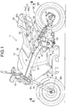
FIG. 1 is a schematic diagram showing a saddle-ride type vehicle, that is, a two-wheeled motor vehicle, according to one embodiment of the present invention. The two-wheeled motor vehicle (the saddle-ride type vehicle) 11 is provided with abody frame 12 and abody cover 13 mounted on thebody frame 12. Thebody frame 12 is provided with ahead pipe 15 for steerably supporting afront fork 14, a pair of right and leftmain frames 16 being extended from thehead pipe 15 backward and downward at a first angle with respect to a horizontal plane, a pair of right andleft pivot frames 17 being connected to rear ends of themain frames 16 atfirst connections 17a and extended downward from rear ends of themain frames 16, a pair of right and left downframes 18 being extended downward at a second angle with respect to the horizontal plane from thehead pipe 15, the second angle being larger than the first angle, and a pair of right and leftlower frames 19 being extended from rear ends of thedown frames 18, the pair oflower frames 19 being connected to thepivot frames 17 atsecond connections 17b belowfirst connections 17a. A front wheel WF is supported rotatably around anaxle 21 by thefront fork 14. - The two-
wheeled motor vehicle 11 is provided with arear wheel unit 22. Therear wheel unit 22 is coupled to thepivot frame 17 via apivot 23 extended horizontally. Therear wheel unit 22 is supported swingably in the up-down direction around thepivot 23 by thepivot frames 17. A rear wheel WR is supported rotatably around anaxle 24 parallel to thepivot 23 by a free end of therear wheel unit 22. Arear cushion 25 is installed between thebody frame 12 and therear wheel unit 22. One end of therear cushion 25 is coupled to thepivot frames 17 at third connections 17c provided above thepivot 23. The transmission of vibration from the rear wheel WR to thebody frame 12 is inhibited when therear cushion 25 regulates fluctuation of therear wheel unit 22 for thebody frame 12. Therear wheel unit 22 is connected to the rear wheel WR and provided with anelectric motor 26 for driving the rear wheel WR on the basis of supplied electric power. - The two-
wheeled motor vehicle 11 is provided with afuel supply assembly 28. Thefuel supply assembly 28 is coupled to themain frame 16 above thepivot frame 17. Thefuel supply assembly 28 is provided with aseat frame 31 being extended backward above the rear wheel WR from themain frames 16, theseat frame 31 supporting an occupant'sseat 29. Theseat frame 31 is configured with a tubular body that guides exhaust gas from a fuel cell unit to the back of the occupant'sseat 29 as described later. The tubular body has a monocoque structure that also functions as an exhaust duct. - The
seat frame 31 is provided with anupper body 31a and alower body 31b. Theupper body 31a and thelower body 31b are made of conductive material such as carbon. Theupper body 31a and thelower body 31b are mutually connected. A connectingface 31c of theupper body 31a and thelower body 31b is provided to both sides from themain frames 16 side to a rear end. The occupant'sseat 29 is mounted on theupper body 31a. An occupant rides on the occupant'sseat 29. A load from the occupant'sseat 29 is applied to theupper body 31a of theseat frame 31. The whole load applied to theseat frame 31 is applied to thelower body 31b of theseat frame 31. Theupper body 31a is detachably connected to thelower body 31b in a state of a completed vehicle. A fastener such as ascrew 58 is used for connecting. Theupper body 31a includes theattachment portion 59 connected to themain frame 16 in front of thefirst connection 17a. A fastener such as a screw is used for connecting. Thelower body 31b is provided with anattachment portion 61 connected to themain frame 16 between thefirst connection 17a and theattachment portion 59. A fastener such as a screw is used for connecting. -
Openings upper body 31a and thelower body 31b at the back of the occupant'sseat 29. Eachopening motor vehicle 11 is placed laterally, light gas in the exhaust duct can be promptly exhausted outside via theopenings - The body cover 13 includes an
upper cover 32 connected to the upsides of the right and leftmain frames 16 in common, aside cover 33 connected to each individualmain frame 16 on the downside of themain frame 16, an air-guidingplate 34 extended forward from a rear end connected to theside cover 33 and arear cover 35 covering theseat frame 31 at the back of the occupant'sseat 29. Theupper cover 32 is connected to themain frames 16 in a state that theupper cover 32 straddles the twomain frames 16 from the upside. Therear cover 35 has anexhaust vent 54b at a rear end of theseat frame 31. - As shown in
FIG. 2 , afuel cell unit 36 is mounted on thebody frame 12. Thefuel cell unit 36 is supported by anupper hanger plate 46 described later from the upside at the back of thehead pipe 15 and is supported by the pair of right and leftlower frames 19 from the downside. As described above, thefuel cell unit 36 is mounted on thebody frame 12 at the back of thehead pipe 15 and in front of thepivot frame 17. The down frames 18 are extended in front of thefuel cell unit 36. Thefuel cell unit 36 has anoutside air intake 38 disposed along animaginary plane 37 perpendicular to a ground surface, extending in a lateral direction of the vehicle, and facing forward. In thefuel cell unit 36, electric power is generated on the basis of chemical reaction of hydrogen and oxygen in the air. Thefuel cell unit 36 utilizes atmospheric air flowing in from theintake 38 in supply of oxygen and cooling. - A
frame cover 39 is coupled to thebody frame 12. Theframe cover 39 is provided with afront wall 39a and aside wall 39b extended toward the rear of the vehicle from both right and left edges of thefront wall 39a. Anintake port 41 is partitioned in theside wall 39b. - A
cylindrical fuel tank 42 is mounted on thebody frame 12. Thefuel tank 42 is extended backward from apressure regulator 43 connected to thefuel cell unit 36. Thefuel tank 42 stores high-pressure hydrogen. Thelower body 31b of theseat frame 31 supports thefuel tank 42 from the downside. Thefuel tank 42 is housed inside theseat frame 31. - A
controller 44 is mounted on thebody frame 12. Thecontroller 44 is arranged below thefuel tank 42 and in front of the rear wheel WR. Thecontroller 44 supplies, to theelectric motor 26, electric power supplied from thefuel cell unit 36. - A
secondary cell 45 is mounted on thebody frame 12. Thesecondary cell 45 is arranged side by side below thefuel cell unit 36 and in front of thecontroller 44. Thesecondary cell 45 charges and discharges electric power according to control of thecontroller 44. - As shown in
FIG. 3 , thebody frame 12 is further provided with theupper hanger plate 46 and alower hanger plate 65. Theupper hanger plate 46 is coupled to the right and leftmain frames 16 in a state that theupper hanger plate 46 straddles the upside of thefuel cell unit 36. In coupling, a fastener such as ascrew 63 is used. An upper end of thefuel cell unit 36 is connected to theupper hanger plate 46. In connecting, a fastener such as ascrew 64 is used. Theupper hanger plate 46 connects thefuel cell unit 36 to the main frames 16. - The
lower hanger plate 65 is coupled to the right and leftlower frames 19 below thefuel cell unit 36. In coupling, a pair of front and rear cross bars 66 are fixed to the right and left lower frames 19. Theindividual cross bar 66 is horizontally extended laterally from the lower frames 19. Thelower hanger plate 65 is fastened to the cross bars 66 by screws. At this time, an elastic member such as a rubber bush is held between thecross bar 66 and thelower hanger plate 65. A lower end of thefuel cell unit 36 is connected to thelower hanger plate 65. In connecting, ascrew 67 is screwed into thelower hanger plate 65 from the downside. Thelower hanger plate 65 connects thefuel cell unit 36 to themain frame 16. - As shown in
FIG. 4 , theframe cover 39 covers the front side of theintake 38, partitioning anair intake space 48 in front of theintake 38. Theintake port 41 is open to the rear side, communicating with theair intake space 48. In forming theintake port 41, a shieldingplate 49 more distant from an imaginary plane PL including theside wall 39b toward the rear side is arranged in an opening of theside wall 39b. Theintake port 41 is formed between a rear end of the shieldingplate 49 and theside wall 39b. - The air-guiding
plate 34 is connected to theframe cover 39 at the back of theintake port 41. The air-guidingplate 34 is open forward so as to form anintroduction space 51 for introducing traveling wind from the front side in a position opposite to theintake port 41, the air-guidingplate 34 being provided to cover each lateral side of theintake port 41 and the shieldingplate 49. - The
fuel cell unit 36 is provided with anexhaust port 53 open rearward along animaginary plane 52 perpendicular to the ground surface and extending in the lateral direction of the vehicle. As described above, thefuel cell unit 36 is provided with theoutside air intake 38 open to the front side of the vehicle at the back of and below an upper end of thehead pipe 15 and theexhaust port 53 open rearward in front of and above thepivot 23. In thefuel cell unit 36, an airflow is circulated from theintake 38 toward theexhaust port 53 by effect of a fan unit built in thefuel cell unit 36. - As shown in
FIG. 5 , theseat frame 31 configures an exhaust duct. As the exhaust duct partitions aventilation duct 54 between theupper body 31a and thelower body 31b. Theventilation duct 54 is open at aninlet 54a at a front end and is extended to anexhaust vent 54b of therear cover 35 at a rear end. Thefuel tank 42 is housed in the exhaust duct. - A
hydrogen sensor 69 is respectively arranged inside theupper cover 32, in the vicinity of theinlet 54a of the exhaust duct (inside an opening-closingportion 68 described later) and in the vicinity of theexhaust vent 54b of the exhaust duct (inside the rear cover 35). Thehydrogen sensor 69 is arranged in the uppermost area of a cavity. When hydrogen exceeding predetermined concentration is detected by anyhydrogen sensor 69, an indicator (not shown) is lit and the indicator tells an occupant the detection, and control for closing thepressure regulator 43 is performed. - The
seat frame 31 is provided with the opening-closingportion 68 above thepressure regulator 43. The opening-closingportion 68 is provided with a hatch for opening and closing an opening for connecting the inside and the outside of the exhaust duct. When the opening-closingportion 68 is opened, gas in the exhaust duct can be emitted outside. Even if hydrogen should accumulate in front side of the exhaust duct, the hydrogen can be promptly exhausted outside the vehicle. - As shown in
FIG. 6 , theinlet 54a at a front end of the exhaust duct is fitted to aframe body 55 for partitioning theexhaust port 53 of thefuel cell unit 36. A sealingmember 56 is held between theframe body 55 and the seat frame (the exhaust duct) 31. The sealingmember 56 is made of flexible rubber material for example. - The
outside air intake 38 of thefuel cell unit 36 mounted on thebody frame 12 is open to the front side of the vehicle at the back of and below the upper end of thehead pipe 15, and theexhaust port 53 of thefuel cell unit 36 is open rearward in front of and above thepivot 23. Theseat frame 31 has the monocoque structure also having a configuration of the exhaust duct for guiding exhaust gas from thefuel cell unit 36 to the back of the occupant'sseat 29. As shown inFIG. 5 , as a linear ventilation path is built in a longitudinal direction of the vehicle from theintake 38 of thefuel cell unit 36 to theexhaust vent 54b of the exhaust duct, efficient ventilation structure in taking outside air in is realized. In addition, as theseat frame 31 forming the tubular body for guiding exhaust gas supports the occupant'sseat 29, a member such as a metal seat rail proper to the occupant'sseat 29 can be omitted and the two-wheeledmotor vehicle 11 can be lightened. - In the two-wheeled
motor vehicle 11, thefuel tank 42 is extended backward from thefuel cell unit 36 and thefuel tank 42 is housed in the exhaust duct. While thefuel cell unit 36 is operated, thefuel tank 42 is cooled because of adiabatic expansion, however, cooling effect is softened by exhaust heat from thefuel cell unit 36. - The front end of the
seat frame 31, that is, the exhaust duct is fitted to theframe body 55 of theexhaust port 53. Accordingly, exhaust gas of thefuel cell unit 36 securely flows into the exhaust duct of theseat frame 31. In addition, the sealingmember 56 is held between theframe body 55 and the seat frame 31 (the exhaust duct). Air leakage is prevented between thefuel cell unit 36 and the exhaust duct. Additionally, the vibration of theseat frame 31 can be absorbed by the sealingmember 56 and vibration transmitted from theseat frame 31 to thefuel cell unit 36 can be inhibited. - The
seat frame 31 is provided with thelower body 31b and theupper body 31a as described above. Theupper body 31a can be separated from thelower body 31b in a state of the completed vehicle. Accordingly, sub-assembly of thefuel tank 42 is possible on thelower body 31b of theseat frame 31 and in addition, in a state of the completed vehicle, maintenance can be readily realized.
Claims (8)
- A saddle-ride type vehicle, comprising:a body frame (12) including right and left main frames (16) and a seat frame (31), the right and left main frames (16) extending from a head pipe (15) steerably supporting a front fork (14) to a pair of right and left pivot frames (17) supporting a rear wheel unit (22) swingably around a pivot (23), the seat frame (31) extending backward above a rear wheel (WR) and supporting an occupant's seat (29) for an occupant to straddle; andan air-cooled fuel cell unit (36) mounted on the body frame (12) at a back of the head pipe (15) and in front of the pivot frame (17), the fuel cell unit (36) using taken-in outside air for supplying oxygen and cooling a unit,wherein the fuel cell unit (36) includes an exhaust port (53) open backward above the pivot (23), andthe seat frame (31) is configured with a tubular body mounted on the main frames (16) and guiding exhaust gas from the fuel cell unit (36) to a back of the occupant's seat (29).
- The saddle-ride type vehicle according to Claim 1, further comprising
a fuel tank (42) connected to the fuel cell unit (36) and extended backward, the fuel tank (42) being housed in the tubular body and supplying stored high-pressure hydrogen to the fuel cell unit (36). - The saddle-ride type vehicle according to Claim 2, wherein
the seat frame (31) comprises:a lower body (31b) receiving a whole load applied to the seat frame (31) and supporting the fuel tank (42); andan upper body (31a) receiving a load from the occupant's seat (29) and covering an upside of the fuel tank (42), the upper body (31a) being detachable from the lower body (31b) in a state of a completed vehicle. - The saddle-ride type vehicle according to Claim 2 or 3, wherein the seat frame (31) is configured with a conductive member.
- The saddle-ride type vehicle according to any one of Claims 2 to 4, wherein the seat frame (31) includes an opening-closing portion above a pressure regulator (43) provided to a fuel supply path connecting the fuel cell unit (36) with the fuel tank (42).
- The saddle-ride type vehicle according to any one of Claims 1 to 5, wherein a front end of the seat frame (31) is fitted to a frame body (55) partitioning the exhaust port (53).
- The saddle-ride type vehicle according to Claim 6, wherein a sealing member (56) is held between the frame body (55) and the seat frame (31).
- The saddle-ride type vehicle according to Claim 6 or 7, wherein the seat frame (31) includes attachment portions (59, 61) attached to the right and left main frames (16) and provided outside the front end of the seat frame (31).
Applications Claiming Priority (2)
| Application Number | Priority Date | Filing Date | Title |
|---|---|---|---|
| JP2016071511 | 2016-03-31 | ||
| JP2016191770A JP6463318B2 (en) | 2016-03-31 | 2016-09-29 | Saddle riding |
Publications (3)
| Publication Number | Publication Date |
|---|---|
| EP3225522A2 true EP3225522A2 (en) | 2017-10-04 |
| EP3225522A3 EP3225522A3 (en) | 2017-10-25 |
| EP3225522B1 EP3225522B1 (en) | 2020-06-10 |
Family
ID=58448437
Family Applications (1)
| Application Number | Title | Priority Date | Filing Date |
|---|---|---|---|
| EP17163257.3A Active EP3225522B1 (en) | 2016-03-31 | 2017-03-28 | Saddle-ride type vehicle |
Country Status (2)
| Country | Link |
|---|---|
| US (1) | US20170282749A1 (en) |
| EP (1) | EP3225522B1 (en) |
Cited By (1)
| Publication number | Priority date | Publication date | Assignee | Title |
|---|---|---|---|---|
| EP3301008A1 (en) * | 2016-09-29 | 2018-04-04 | Honda Motor Co., Ltd. | Saddle-riding-type electric vehicle fuel cell stack fixation structure |
Families Citing this family (3)
| Publication number | Priority date | Publication date | Assignee | Title |
|---|---|---|---|---|
| JP6331157B2 (en) * | 2016-03-31 | 2018-05-30 | 本田技研工業株式会社 | Seat mounting structure for saddle-ride type vehicles |
| US11142285B2 (en) * | 2017-09-11 | 2021-10-12 | Honda Motor Co., Ltd. | Electric motorcycle |
| DE112018007170T5 (en) | 2018-03-29 | 2020-11-05 | Honda Motor Co., Ltd. | Electric vehicle of the straddle seat type |
Citations (1)
| Publication number | Priority date | Publication date | Assignee | Title |
|---|---|---|---|---|
| JP2009078622A (en) | 2007-09-25 | 2009-04-16 | Suzuki Motor Corp | Fuel cell two-wheel vehicle |
Family Cites Families (31)
| Publication number | Priority date | Publication date | Assignee | Title |
|---|---|---|---|---|
| US4475622A (en) * | 1981-11-25 | 1984-10-09 | Honda Giken Kogyo Kabushiki Kaisha | Exhaust system for motor vehicles |
| JPS6028716B2 (en) * | 1982-09-11 | 1985-07-06 | 本田技研工業株式会社 | Engine cooling systems for motorcycles, etc. |
| JPS5953281A (en) * | 1982-09-20 | 1984-03-27 | 本田技研工業株式会社 | Motorcycle |
| US6238017B1 (en) * | 1997-10-03 | 2001-05-29 | Frederick G. Eitel | Advanced motorcycle chassis and braking system |
| US6695088B2 (en) * | 2001-06-28 | 2004-02-24 | Honda Giken Kogyo Kabushiki Kaisha | Air management system for a motorcycle |
| JP4087668B2 (en) * | 2002-09-10 | 2008-05-21 | 本田技研工業株式会社 | Seat rail structure |
| JP2004098884A (en) * | 2002-09-10 | 2004-04-02 | Honda Motor Co Ltd | Rear part structure for motorcycle |
| JP2004249774A (en) * | 2003-02-18 | 2004-09-09 | Yamaha Motor Co Ltd | Motorcycle |
| JP4463639B2 (en) * | 2004-08-06 | 2010-05-19 | 本田技研工業株式会社 | Cooling structure for electric vehicles |
| JP4523362B2 (en) * | 2004-08-20 | 2010-08-11 | 本田技研工業株式会社 | Fuel cell vehicle |
| EP1710155B1 (en) * | 2005-04-04 | 2008-08-13 | HONDA MOTOR CO., Ltd. | Motorcycle with fuel cell |
| JP2007099059A (en) * | 2005-10-04 | 2007-04-19 | Yamaha Motor Co Ltd | Hydrogen storage container-mounted motorcycle |
| JP4771410B2 (en) * | 2005-10-25 | 2011-09-14 | 本田技研工業株式会社 | Fuel cell motorcycle |
| JP2008100574A (en) * | 2006-10-18 | 2008-05-01 | Yamaha Motor Co Ltd | Motorcycle |
| JP4998942B2 (en) * | 2007-03-06 | 2012-08-15 | 本田技研工業株式会社 | Fuel cell motorcycle |
| JP5035886B2 (en) * | 2007-03-30 | 2012-09-26 | 本田技研工業株式会社 | Saddle type fuel cell vehicle |
| US7743868B2 (en) * | 2007-06-20 | 2010-06-29 | Buell Motorcycle Company | Radiator mounting for a motorcycle |
| JP2009184589A (en) * | 2008-02-08 | 2009-08-20 | Yamaha Motor Co Ltd | Saddle riding type vehicle |
| ATE508263T1 (en) * | 2009-01-26 | 2011-05-15 | Yamaha Motor Europ | MOTORCYCLE WITH AN EMISSION CONTROL DEVICE OF IMPROVED DESIGN |
| JP5417992B2 (en) * | 2009-05-27 | 2014-02-19 | スズキ株式会社 | Fuel cell vehicle |
| JP5461162B2 (en) * | 2009-12-07 | 2014-04-02 | 本田技研工業株式会社 | Rear structure of saddle-ride type vehicle |
| US9027694B2 (en) * | 2010-11-18 | 2015-05-12 | Kawasaki Jukogyo Kabushiki Kaisha | Saddle-type electric vehicle |
| EP2657114B1 (en) * | 2010-12-24 | 2016-05-11 | Kawasaki Jukogyo Kabushiki Kaisha | Saddle-type electric vehicle |
| US9090301B2 (en) * | 2010-12-27 | 2015-07-28 | Kawasaki Jukogyo Kabushiki Kaisha | Electric motorcycle |
| US8899369B2 (en) * | 2010-12-27 | 2014-12-02 | Kawasaki Jukogyo Kabushiki Kaisha | Straddle-type electric vehicle, and mounting structure of electric power controller in electric vehicle |
| US9296444B2 (en) * | 2011-12-28 | 2016-03-29 | Kawasaki Jukogyo Kabushiki Kaisha | Straddle electric vehicle |
| JP2014177242A (en) * | 2013-03-15 | 2014-09-25 | Yamaha Motor Co Ltd | Saddle-riding type vehicle |
| US9902458B2 (en) * | 2013-09-05 | 2018-02-27 | Honda Motor Co., Ltd. | Vehicle body frame structure for saddled vehicle |
| JP6536353B2 (en) * | 2015-10-27 | 2019-07-03 | スズキ株式会社 | Converter arrangement structure of electric vehicle |
| JP2017081326A (en) * | 2015-10-27 | 2017-05-18 | スズキ株式会社 | Piping joint arrangement structure of fuel battery two-wheel vehicle |
| JP6433031B2 (en) * | 2016-09-29 | 2018-12-05 | 本田技研工業株式会社 | Fuel cell stack fixing structure for saddle-ride type electric vehicle |
-
2017
- 2017-02-28 US US15/444,818 patent/US20170282749A1/en not_active Abandoned
- 2017-03-28 EP EP17163257.3A patent/EP3225522B1/en active Active
Patent Citations (1)
| Publication number | Priority date | Publication date | Assignee | Title |
|---|---|---|---|---|
| JP2009078622A (en) | 2007-09-25 | 2009-04-16 | Suzuki Motor Corp | Fuel cell two-wheel vehicle |
Cited By (2)
| Publication number | Priority date | Publication date | Assignee | Title |
|---|---|---|---|---|
| EP3301008A1 (en) * | 2016-09-29 | 2018-04-04 | Honda Motor Co., Ltd. | Saddle-riding-type electric vehicle fuel cell stack fixation structure |
| US10479434B2 (en) | 2016-09-29 | 2019-11-19 | Honda Motor Co., Ltd. | Saddle-riding-type electric vehicle fuel cell stack fixation structure |
Also Published As
| Publication number | Publication date |
|---|---|
| EP3225522B1 (en) | 2020-06-10 |
| EP3225522A3 (en) | 2017-10-25 |
| US20170282749A1 (en) | 2017-10-05 |
Similar Documents
| Publication | Publication Date | Title |
|---|---|---|
| EP3225522B1 (en) | Saddle-ride type vehicle | |
| US9543598B2 (en) | Fuel cell-powered motorcycle | |
| US10252637B2 (en) | Saddle-ride vehicle | |
| JP6463318B2 (en) | Saddle riding | |
| JP2006335243A (en) | Power supply device for vehicle | |
| US8479857B2 (en) | Fuel cell powered vehicle | |
| US20140224562A1 (en) | Fuel cell vehicle | |
| JP2009006971A (en) | Saddle riding type fuel cell vehicle | |
| JP2008247324A (en) | Saddle-ride type fuel cell powered vehicle | |
| US7913784B2 (en) | Saddle ride, fuel cell powered vehicle | |
| ITTO20080231A1 (en) | SADDLE VEHICLE OPERATED FROM A FUEL STACK. | |
| EP4026723A1 (en) | Fuel cell vehicle | |
| JP6648518B2 (en) | Hydrogen dilution equipment for fuel cell vehicles | |
| KR100879426B1 (en) | Motorcycle | |
| JP6666771B2 (en) | Saddle type vehicle | |
| JP2006339048A (en) | Battery-cooling structure | |
| JP5407546B2 (en) | Fuel cell vehicle | |
| JP2016084026A (en) | vehicle | |
| US9855836B2 (en) | Electric vehicle | |
| JP6723891B2 (en) | Saddle type vehicle | |
| JP2011255827A (en) | Fuel cell motorcycle | |
| EP4026715B1 (en) | Fuel cell vehicle | |
| US20170113568A1 (en) | Electric vehicle | |
| JP2011079346A (en) | Fuel cell vehicle |
Legal Events
| Date | Code | Title | Description |
|---|---|---|---|
| PUAI | Public reference made under article 153(3) epc to a published international application that has entered the european phase |
Free format text: ORIGINAL CODE: 0009012 |
|
| STAA | Information on the status of an ep patent application or granted ep patent |
Free format text: STATUS: REQUEST FOR EXAMINATION WAS MADE |
|
| PUAL | Search report despatched |
Free format text: ORIGINAL CODE: 0009013 |
|
| 17P | Request for examination filed |
Effective date: 20170328 |
|
| AK | Designated contracting states |
Kind code of ref document: A2 Designated state(s): AL AT BE BG CH CY CZ DE DK EE ES FI FR GB GR HR HU IE IS IT LI LT LU LV MC MK MT NL NO PL PT RO RS SE SI SK SM TR |
|
| AX | Request for extension of the european patent |
Extension state: BA ME |
|
| AK | Designated contracting states |
Kind code of ref document: A3 Designated state(s): AL AT BE BG CH CY CZ DE DK EE ES FI FR GB GR HR HU IE IS IT LI LT LU LV MC MK MT NL NO PL PT RO RS SE SI SK SM TR |
|
| AX | Request for extension of the european patent |
Extension state: BA ME |
|
| RIC1 | Information provided on ipc code assigned before grant |
Ipc: H01M 8/00 20160101ALI20170920BHEP Ipc: B60L 11/18 20060101ALI20170920BHEP Ipc: B62K 11/00 20060101AFI20170920BHEP Ipc: B62M 7/04 20060101ALI20170920BHEP |
|
| STAA | Information on the status of an ep patent application or granted ep patent |
Free format text: STATUS: EXAMINATION IS IN PROGRESS |
|
| 17Q | First examination report despatched |
Effective date: 20191111 |
|
| RIC1 | Information provided on ipc code assigned before grant |
Ipc: B62M 7/04 20060101ALI20200103BHEP Ipc: H01M 8/00 20160101ALI20200103BHEP Ipc: B62K 11/00 20060101AFI20200103BHEP |
|
| GRAP | Despatch of communication of intention to grant a patent |
Free format text: ORIGINAL CODE: EPIDOSNIGR1 |
|
| STAA | Information on the status of an ep patent application or granted ep patent |
Free format text: STATUS: GRANT OF PATENT IS INTENDED |
|
| INTG | Intention to grant announced |
Effective date: 20200217 |
|
| GRAS | Grant fee paid |
Free format text: ORIGINAL CODE: EPIDOSNIGR3 |
|
| GRAA | (expected) grant |
Free format text: ORIGINAL CODE: 0009210 |
|
| STAA | Information on the status of an ep patent application or granted ep patent |
Free format text: STATUS: THE PATENT HAS BEEN GRANTED |
|
| AK | Designated contracting states |
Kind code of ref document: B1 Designated state(s): AL AT BE BG CH CY CZ DE DK EE ES FI FR GB GR HR HU IE IS IT LI LT LU LV MC MK MT NL NO PL PT RO RS SE SI SK SM TR |
|
| REG | Reference to a national code |
Ref country code: GB Ref legal event code: FG4D |
|
| REG | Reference to a national code |
Ref country code: CH Ref legal event code: EP Ref country code: AT Ref legal event code: REF Ref document number: 1278964 Country of ref document: AT Kind code of ref document: T Effective date: 20200615 |
|
| REG | Reference to a national code |
Ref country code: DE Ref legal event code: R096 Ref document number: 602017017870 Country of ref document: DE |
|
| REG | Reference to a national code |
Ref country code: IE Ref legal event code: FG4D |
|
| REG | Reference to a national code |
Ref country code: LT Ref legal event code: MG4D |
|
| PG25 | Lapsed in a contracting state [announced via postgrant information from national office to epo] |
Ref country code: SE Free format text: LAPSE BECAUSE OF FAILURE TO SUBMIT A TRANSLATION OF THE DESCRIPTION OR TO PAY THE FEE WITHIN THE PRESCRIBED TIME-LIMIT Effective date: 20200610 Ref country code: GR Free format text: LAPSE BECAUSE OF FAILURE TO SUBMIT A TRANSLATION OF THE DESCRIPTION OR TO PAY THE FEE WITHIN THE PRESCRIBED TIME-LIMIT Effective date: 20200911 Ref country code: NO Free format text: LAPSE BECAUSE OF FAILURE TO SUBMIT A TRANSLATION OF THE DESCRIPTION OR TO PAY THE FEE WITHIN THE PRESCRIBED TIME-LIMIT Effective date: 20200910 Ref country code: LT Free format text: LAPSE BECAUSE OF FAILURE TO SUBMIT A TRANSLATION OF THE DESCRIPTION OR TO PAY THE FEE WITHIN THE PRESCRIBED TIME-LIMIT Effective date: 20200610 Ref country code: FI Free format text: LAPSE BECAUSE OF FAILURE TO SUBMIT A TRANSLATION OF THE DESCRIPTION OR TO PAY THE FEE WITHIN THE PRESCRIBED TIME-LIMIT Effective date: 20200610 |
|
| REG | Reference to a national code |
Ref country code: NL Ref legal event code: MP Effective date: 20200610 |
|
| PG25 | Lapsed in a contracting state [announced via postgrant information from national office to epo] |
Ref country code: LV Free format text: LAPSE BECAUSE OF FAILURE TO SUBMIT A TRANSLATION OF THE DESCRIPTION OR TO PAY THE FEE WITHIN THE PRESCRIBED TIME-LIMIT Effective date: 20200610 Ref country code: HR Free format text: LAPSE BECAUSE OF FAILURE TO SUBMIT A TRANSLATION OF THE DESCRIPTION OR TO PAY THE FEE WITHIN THE PRESCRIBED TIME-LIMIT Effective date: 20200610 Ref country code: BG Free format text: LAPSE BECAUSE OF FAILURE TO SUBMIT A TRANSLATION OF THE DESCRIPTION OR TO PAY THE FEE WITHIN THE PRESCRIBED TIME-LIMIT Effective date: 20200910 Ref country code: RS Free format text: LAPSE BECAUSE OF FAILURE TO SUBMIT A TRANSLATION OF THE DESCRIPTION OR TO PAY THE FEE WITHIN THE PRESCRIBED TIME-LIMIT Effective date: 20200610 |
|
| REG | Reference to a national code |
Ref country code: AT Ref legal event code: MK05 Ref document number: 1278964 Country of ref document: AT Kind code of ref document: T Effective date: 20200610 |
|
| PG25 | Lapsed in a contracting state [announced via postgrant information from national office to epo] |
Ref country code: NL Free format text: LAPSE BECAUSE OF FAILURE TO SUBMIT A TRANSLATION OF THE DESCRIPTION OR TO PAY THE FEE WITHIN THE PRESCRIBED TIME-LIMIT Effective date: 20200610 Ref country code: AL Free format text: LAPSE BECAUSE OF FAILURE TO SUBMIT A TRANSLATION OF THE DESCRIPTION OR TO PAY THE FEE WITHIN THE PRESCRIBED TIME-LIMIT Effective date: 20200610 |
|
| PG25 | Lapsed in a contracting state [announced via postgrant information from national office to epo] |
Ref country code: IT Free format text: LAPSE BECAUSE OF FAILURE TO SUBMIT A TRANSLATION OF THE DESCRIPTION OR TO PAY THE FEE WITHIN THE PRESCRIBED TIME-LIMIT Effective date: 20200610 Ref country code: ES Free format text: LAPSE BECAUSE OF FAILURE TO SUBMIT A TRANSLATION OF THE DESCRIPTION OR TO PAY THE FEE WITHIN THE PRESCRIBED TIME-LIMIT Effective date: 20200610 Ref country code: PT Free format text: LAPSE BECAUSE OF FAILURE TO SUBMIT A TRANSLATION OF THE DESCRIPTION OR TO PAY THE FEE WITHIN THE PRESCRIBED TIME-LIMIT Effective date: 20201012 Ref country code: EE Free format text: LAPSE BECAUSE OF FAILURE TO SUBMIT A TRANSLATION OF THE DESCRIPTION OR TO PAY THE FEE WITHIN THE PRESCRIBED TIME-LIMIT Effective date: 20200610 Ref country code: SM Free format text: LAPSE BECAUSE OF FAILURE TO SUBMIT A TRANSLATION OF THE DESCRIPTION OR TO PAY THE FEE WITHIN THE PRESCRIBED TIME-LIMIT Effective date: 20200610 Ref country code: CZ Free format text: LAPSE BECAUSE OF FAILURE TO SUBMIT A TRANSLATION OF THE DESCRIPTION OR TO PAY THE FEE WITHIN THE PRESCRIBED TIME-LIMIT Effective date: 20200610 Ref country code: RO Free format text: LAPSE BECAUSE OF FAILURE TO SUBMIT A TRANSLATION OF THE DESCRIPTION OR TO PAY THE FEE WITHIN THE PRESCRIBED TIME-LIMIT Effective date: 20200610 Ref country code: AT Free format text: LAPSE BECAUSE OF FAILURE TO SUBMIT A TRANSLATION OF THE DESCRIPTION OR TO PAY THE FEE WITHIN THE PRESCRIBED TIME-LIMIT Effective date: 20200610 |
|
| PG25 | Lapsed in a contracting state [announced via postgrant information from national office to epo] |
Ref country code: PL Free format text: LAPSE BECAUSE OF FAILURE TO SUBMIT A TRANSLATION OF THE DESCRIPTION OR TO PAY THE FEE WITHIN THE PRESCRIBED TIME-LIMIT Effective date: 20200610 Ref country code: SK Free format text: LAPSE BECAUSE OF FAILURE TO SUBMIT A TRANSLATION OF THE DESCRIPTION OR TO PAY THE FEE WITHIN THE PRESCRIBED TIME-LIMIT Effective date: 20200610 Ref country code: IS Free format text: LAPSE BECAUSE OF FAILURE TO SUBMIT A TRANSLATION OF THE DESCRIPTION OR TO PAY THE FEE WITHIN THE PRESCRIBED TIME-LIMIT Effective date: 20201010 |
|
| REG | Reference to a national code |
Ref country code: DE Ref legal event code: R097 Ref document number: 602017017870 Country of ref document: DE |
|
| PLBE | No opposition filed within time limit |
Free format text: ORIGINAL CODE: 0009261 |
|
| STAA | Information on the status of an ep patent application or granted ep patent |
Free format text: STATUS: NO OPPOSITION FILED WITHIN TIME LIMIT |
|
| PG25 | Lapsed in a contracting state [announced via postgrant information from national office to epo] |
Ref country code: DK Free format text: LAPSE BECAUSE OF FAILURE TO SUBMIT A TRANSLATION OF THE DESCRIPTION OR TO PAY THE FEE WITHIN THE PRESCRIBED TIME-LIMIT Effective date: 20200610 |
|
| 26N | No opposition filed |
Effective date: 20210311 |
|
| PG25 | Lapsed in a contracting state [announced via postgrant information from national office to epo] |
Ref country code: SI Free format text: LAPSE BECAUSE OF FAILURE TO SUBMIT A TRANSLATION OF THE DESCRIPTION OR TO PAY THE FEE WITHIN THE PRESCRIBED TIME-LIMIT Effective date: 20200610 |
|
| REG | Reference to a national code |
Ref country code: DE Ref legal event code: R084 Ref document number: 602017017870 Country of ref document: DE |
|
| PG25 | Lapsed in a contracting state [announced via postgrant information from national office to epo] |
Ref country code: MC Free format text: LAPSE BECAUSE OF FAILURE TO SUBMIT A TRANSLATION OF THE DESCRIPTION OR TO PAY THE FEE WITHIN THE PRESCRIBED TIME-LIMIT Effective date: 20200610 |
|
| REG | Reference to a national code |
Ref country code: CH Ref legal event code: PL |
|
| GBPC | Gb: european patent ceased through non-payment of renewal fee |
Effective date: 20210328 |
|
| REG | Reference to a national code |
Ref country code: BE Ref legal event code: MM Effective date: 20210331 |
|
| PG25 | Lapsed in a contracting state [announced via postgrant information from national office to epo] |
Ref country code: IE Free format text: LAPSE BECAUSE OF NON-PAYMENT OF DUE FEES Effective date: 20210328 Ref country code: GB Free format text: LAPSE BECAUSE OF NON-PAYMENT OF DUE FEES Effective date: 20210328 Ref country code: FR Free format text: LAPSE BECAUSE OF NON-PAYMENT OF DUE FEES Effective date: 20210331 Ref country code: LI Free format text: LAPSE BECAUSE OF NON-PAYMENT OF DUE FEES Effective date: 20210331 Ref country code: LU Free format text: LAPSE BECAUSE OF NON-PAYMENT OF DUE FEES Effective date: 20210328 Ref country code: CH Free format text: LAPSE BECAUSE OF NON-PAYMENT OF DUE FEES Effective date: 20210331 |
|
| PG25 | Lapsed in a contracting state [announced via postgrant information from national office to epo] |
Ref country code: BE Free format text: LAPSE BECAUSE OF NON-PAYMENT OF DUE FEES Effective date: 20210331 |
|
| PG25 | Lapsed in a contracting state [announced via postgrant information from national office to epo] |
Ref country code: HU Free format text: LAPSE BECAUSE OF FAILURE TO SUBMIT A TRANSLATION OF THE DESCRIPTION OR TO PAY THE FEE WITHIN THE PRESCRIBED TIME-LIMIT; INVALID AB INITIO Effective date: 20170328 |
|
| PG25 | Lapsed in a contracting state [announced via postgrant information from national office to epo] |
Ref country code: CY Free format text: LAPSE BECAUSE OF FAILURE TO SUBMIT A TRANSLATION OF THE DESCRIPTION OR TO PAY THE FEE WITHIN THE PRESCRIBED TIME-LIMIT Effective date: 20200610 |
|
| PG25 | Lapsed in a contracting state [announced via postgrant information from national office to epo] |
Ref country code: MK Free format text: LAPSE BECAUSE OF FAILURE TO SUBMIT A TRANSLATION OF THE DESCRIPTION OR TO PAY THE FEE WITHIN THE PRESCRIBED TIME-LIMIT Effective date: 20200610 |
|
| PGFP | Annual fee paid to national office [announced via postgrant information from national office to epo] |
Ref country code: DE Payment date: 20240220 Year of fee payment: 8 |