EP3300834B1 - Bearing thermal relief fan drive gear system assembly method - Google Patents
Bearing thermal relief fan drive gear system assembly method Download PDFInfo
- Publication number
- EP3300834B1 EP3300834B1 EP17202625.4A EP17202625A EP3300834B1 EP 3300834 B1 EP3300834 B1 EP 3300834B1 EP 17202625 A EP17202625 A EP 17202625A EP 3300834 B1 EP3300834 B1 EP 3300834B1
- Authority
- EP
- European Patent Office
- Prior art keywords
- shaft
- expansion
- bearing assembly
- recited
- component
- Prior art date
- Legal status (The legal status is an assumption and is not a legal conclusion. Google has not performed a legal analysis and makes no representation as to the accuracy of the status listed.)
- Active
Links
Images



Classifications
-
- F—MECHANICAL ENGINEERING; LIGHTING; HEATING; WEAPONS; BLASTING
- F16—ENGINEERING ELEMENTS AND UNITS; GENERAL MEASURES FOR PRODUCING AND MAINTAINING EFFECTIVE FUNCTIONING OF MACHINES OR INSTALLATIONS; THERMAL INSULATION IN GENERAL
- F16C—SHAFTS; FLEXIBLE SHAFTS; ELEMENTS OR CRANKSHAFT MECHANISMS; ROTARY BODIES OTHER THAN GEARING ELEMENTS; BEARINGS
- F16C43/00—Assembling bearings
- F16C43/04—Assembling rolling-contact bearings
- F16C43/06—Placing rolling bodies in cages or bearings
- F16C43/08—Placing rolling bodies in cages or bearings by deforming the cages or the races
-
- B—PERFORMING OPERATIONS; TRANSPORTING
- B23—MACHINE TOOLS; METAL-WORKING NOT OTHERWISE PROVIDED FOR
- B23P—METAL-WORKING NOT OTHERWISE PROVIDED FOR; COMBINED OPERATIONS; UNIVERSAL MACHINE TOOLS
- B23P11/00—Connecting or disconnecting metal parts or objects by metal-working techniques not otherwise provided for
- B23P11/02—Connecting or disconnecting metal parts or objects by metal-working techniques not otherwise provided for by first expanding and then shrinking or vice versa, e.g. by using pressure fluids; by making force fits
- B23P11/025—Connecting or disconnecting metal parts or objects by metal-working techniques not otherwise provided for by first expanding and then shrinking or vice versa, e.g. by using pressure fluids; by making force fits by using heat or cold
-
- F—MECHANICAL ENGINEERING; LIGHTING; HEATING; WEAPONS; BLASTING
- F01—MACHINES OR ENGINES IN GENERAL; ENGINE PLANTS IN GENERAL; STEAM ENGINES
- F01D—NON-POSITIVE DISPLACEMENT MACHINES OR ENGINES, e.g. STEAM TURBINES
- F01D25/00—Component parts, details, or accessories, not provided for in, or of interest apart from, other groups
- F01D25/16—Arrangement of bearings; Supporting or mounting bearings in casings
-
- F—MECHANICAL ENGINEERING; LIGHTING; HEATING; WEAPONS; BLASTING
- F01—MACHINES OR ENGINES IN GENERAL; ENGINE PLANTS IN GENERAL; STEAM ENGINES
- F01D—NON-POSITIVE DISPLACEMENT MACHINES OR ENGINES, e.g. STEAM TURBINES
- F01D5/00—Blades; Blade-carrying members; Heating, heat-insulating, cooling or antivibration means on the blades or the members
- F01D5/02—Blade-carrying members, e.g. rotors
- F01D5/026—Shaft to shaft connections
-
- F—MECHANICAL ENGINEERING; LIGHTING; HEATING; WEAPONS; BLASTING
- F02—COMBUSTION ENGINES; HOT-GAS OR COMBUSTION-PRODUCT ENGINE PLANTS
- F02C—GAS-TURBINE PLANTS; AIR INTAKES FOR JET-PROPULSION PLANTS; CONTROLLING FUEL SUPPLY IN AIR-BREATHING JET-PROPULSION PLANTS
- F02C7/00—Features, components parts, details or accessories, not provided for in, or of interest apart form groups F02C1/00 - F02C6/00; Air intakes for jet-propulsion plants
- F02C7/36—Power transmission arrangements between the different shafts of the gas turbine plant, or between the gas-turbine plant and the power user
-
- F—MECHANICAL ENGINEERING; LIGHTING; HEATING; WEAPONS; BLASTING
- F16—ENGINEERING ELEMENTS AND UNITS; GENERAL MEASURES FOR PRODUCING AND MAINTAINING EFFECTIVE FUNCTIONING OF MACHINES OR INSTALLATIONS; THERMAL INSULATION IN GENERAL
- F16C—SHAFTS; FLEXIBLE SHAFTS; ELEMENTS OR CRANKSHAFT MECHANISMS; ROTARY BODIES OTHER THAN GEARING ELEMENTS; BEARINGS
- F16C19/00—Bearings with rolling contact, for exclusively rotary movement
- F16C19/52—Bearings with rolling contact, for exclusively rotary movement with devices affected by abnormal or undesired conditions
- F16C19/525—Bearings with rolling contact, for exclusively rotary movement with devices affected by abnormal or undesired conditions related to temperature and heat, e.g. insulation
-
- F—MECHANICAL ENGINEERING; LIGHTING; HEATING; WEAPONS; BLASTING
- F16—ENGINEERING ELEMENTS AND UNITS; GENERAL MEASURES FOR PRODUCING AND MAINTAINING EFFECTIVE FUNCTIONING OF MACHINES OR INSTALLATIONS; THERMAL INSULATION IN GENERAL
- F16C—SHAFTS; FLEXIBLE SHAFTS; ELEMENTS OR CRANKSHAFT MECHANISMS; ROTARY BODIES OTHER THAN GEARING ELEMENTS; BEARINGS
- F16C35/00—Rigid support of bearing units; Housings, e.g. caps, covers
- F16C35/04—Rigid support of bearing units; Housings, e.g. caps, covers in the case of ball or roller bearings
- F16C35/06—Mounting or dismounting of ball or roller bearings; Fixing them onto shaft or in housing
- F16C35/063—Fixing them on the shaft
-
- F—MECHANICAL ENGINEERING; LIGHTING; HEATING; WEAPONS; BLASTING
- F16—ENGINEERING ELEMENTS AND UNITS; GENERAL MEASURES FOR PRODUCING AND MAINTAINING EFFECTIVE FUNCTIONING OF MACHINES OR INSTALLATIONS; THERMAL INSULATION IN GENERAL
- F16C—SHAFTS; FLEXIBLE SHAFTS; ELEMENTS OR CRANKSHAFT MECHANISMS; ROTARY BODIES OTHER THAN GEARING ELEMENTS; BEARINGS
- F16C35/00—Rigid support of bearing units; Housings, e.g. caps, covers
- F16C35/04—Rigid support of bearing units; Housings, e.g. caps, covers in the case of ball or roller bearings
- F16C35/06—Mounting or dismounting of ball or roller bearings; Fixing them onto shaft or in housing
- F16C35/067—Fixing them in a housing
-
- F—MECHANICAL ENGINEERING; LIGHTING; HEATING; WEAPONS; BLASTING
- F16—ENGINEERING ELEMENTS AND UNITS; GENERAL MEASURES FOR PRODUCING AND MAINTAINING EFFECTIVE FUNCTIONING OF MACHINES OR INSTALLATIONS; THERMAL INSULATION IN GENERAL
- F16D—COUPLINGS FOR TRANSMITTING ROTATION; CLUTCHES; BRAKES
- F16D1/00—Couplings for rigidly connecting two coaxial shafts or other movable machine elements
- F16D1/10—Quick-acting couplings in which the parts are connected by simply bringing them together axially
- F16D1/101—Quick-acting couplings in which the parts are connected by simply bringing them together axially without axial retaining means rotating with the coupling
-
- F—MECHANICAL ENGINEERING; LIGHTING; HEATING; WEAPONS; BLASTING
- F05—INDEXING SCHEMES RELATING TO ENGINES OR PUMPS IN VARIOUS SUBCLASSES OF CLASSES F01-F04
- F05D—INDEXING SCHEME FOR ASPECTS RELATING TO NON-POSITIVE-DISPLACEMENT MACHINES OR ENGINES, GAS-TURBINES OR JET-PROPULSION PLANTS
- F05D2230/00—Manufacture
- F05D2230/60—Assembly methods
-
- F—MECHANICAL ENGINEERING; LIGHTING; HEATING; WEAPONS; BLASTING
- F05—INDEXING SCHEMES RELATING TO ENGINES OR PUMPS IN VARIOUS SUBCLASSES OF CLASSES F01-F04
- F05D—INDEXING SCHEME FOR ASPECTS RELATING TO NON-POSITIVE-DISPLACEMENT MACHINES OR ENGINES, GAS-TURBINES OR JET-PROPULSION PLANTS
- F05D2260/00—Function
- F05D2260/30—Retaining components in desired mutual position
- F05D2260/37—Retaining components in desired mutual position by a press fit connection
-
- F—MECHANICAL ENGINEERING; LIGHTING; HEATING; WEAPONS; BLASTING
- F16—ENGINEERING ELEMENTS AND UNITS; GENERAL MEASURES FOR PRODUCING AND MAINTAINING EFFECTIVE FUNCTIONING OF MACHINES OR INSTALLATIONS; THERMAL INSULATION IN GENERAL
- F16B—DEVICES FOR FASTENING OR SECURING CONSTRUCTIONAL ELEMENTS OR MACHINE PARTS TOGETHER, e.g. NAILS, BOLTS, CIRCLIPS, CLAMPS, CLIPS OR WEDGES; JOINTS OR JOINTING
- F16B4/00—Shrinkage connections, e.g. assembled with the parts at different temperature; Force fits; Non-releasable friction-grip fastenings
- F16B4/006—Shrinkage connections, e.g. assembled with the parts being at different temperature
- F16B4/008—Shrinkage connections, e.g. assembled with the parts being at different temperature using heat-recoverable, i.e. shrinkable, sleeves
-
- F—MECHANICAL ENGINEERING; LIGHTING; HEATING; WEAPONS; BLASTING
- F16—ENGINEERING ELEMENTS AND UNITS; GENERAL MEASURES FOR PRODUCING AND MAINTAINING EFFECTIVE FUNCTIONING OF MACHINES OR INSTALLATIONS; THERMAL INSULATION IN GENERAL
- F16C—SHAFTS; FLEXIBLE SHAFTS; ELEMENTS OR CRANKSHAFT MECHANISMS; ROTARY BODIES OTHER THAN GEARING ELEMENTS; BEARINGS
- F16C19/00—Bearings with rolling contact, for exclusively rotary movement
- F16C19/02—Bearings with rolling contact, for exclusively rotary movement with bearing balls essentially of the same size in one or more circular rows
- F16C19/04—Bearings with rolling contact, for exclusively rotary movement with bearing balls essentially of the same size in one or more circular rows for radial load mainly
- F16C19/06—Bearings with rolling contact, for exclusively rotary movement with bearing balls essentially of the same size in one or more circular rows for radial load mainly with a single row or balls
-
- F—MECHANICAL ENGINEERING; LIGHTING; HEATING; WEAPONS; BLASTING
- F16—ENGINEERING ELEMENTS AND UNITS; GENERAL MEASURES FOR PRODUCING AND MAINTAINING EFFECTIVE FUNCTIONING OF MACHINES OR INSTALLATIONS; THERMAL INSULATION IN GENERAL
- F16C—SHAFTS; FLEXIBLE SHAFTS; ELEMENTS OR CRANKSHAFT MECHANISMS; ROTARY BODIES OTHER THAN GEARING ELEMENTS; BEARINGS
- F16C2226/00—Joining parts; Fastening; Assembling or mounting parts
- F16C2226/10—Force connections, e.g. clamping
- F16C2226/14—Force connections, e.g. clamping by shrink fit, i.e. heating and shrinking part to allow assembly
-
- F—MECHANICAL ENGINEERING; LIGHTING; HEATING; WEAPONS; BLASTING
- F16—ENGINEERING ELEMENTS AND UNITS; GENERAL MEASURES FOR PRODUCING AND MAINTAINING EFFECTIVE FUNCTIONING OF MACHINES OR INSTALLATIONS; THERMAL INSULATION IN GENERAL
- F16C—SHAFTS; FLEXIBLE SHAFTS; ELEMENTS OR CRANKSHAFT MECHANISMS; ROTARY BODIES OTHER THAN GEARING ELEMENTS; BEARINGS
- F16C2360/00—Engines or pumps
- F16C2360/23—Gas turbine engines
-
- F—MECHANICAL ENGINEERING; LIGHTING; HEATING; WEAPONS; BLASTING
- F16—ENGINEERING ELEMENTS AND UNITS; GENERAL MEASURES FOR PRODUCING AND MAINTAINING EFFECTIVE FUNCTIONING OF MACHINES OR INSTALLATIONS; THERMAL INSULATION IN GENERAL
- F16D—COUPLINGS FOR TRANSMITTING ROTATION; CLUTCHES; BRAKES
- F16D1/00—Couplings for rigidly connecting two coaxial shafts or other movable machine elements
- F16D1/10—Quick-acting couplings in which the parts are connected by simply bringing them together axially
- F16D2001/103—Quick-acting couplings in which the parts are connected by simply bringing them together axially the torque is transmitted via splined connections
Definitions
- the present application relates to a method of assembling mating components.
- a gas turbine engine typically includes a fan section, a compressor section, a combustor section and a turbine section. Air entering the compressor section is compressed and delivered into the combustion section where it is mixed with fuel and ignited to generate a high-speed exhaust gas flow. The high-speed exhaust gas flow expands through the turbine section to drive the compressor and the fan section.
- a speed reduction device such as a gear assembly may be utilized to drive the fan section such that the fan section may rotate at a speed different than the turbine section so as to increase the overall propulsive efficiency of the engine.
- a shaft driven by the turbine section provides an input to the gear assembly.
- the shaft may be constructed from multiple sections assembled together. Assembly of the various shaft sections may be performed utilizing press fits.
- a press fit assembly may include heating of one part to allow another part to fit therein. Heating to expand one component is complicated if several components are within a heated region. Non-uniform heating of some portions of a shaft interface can induce unwanted stress on parts, such as bearing assemblies. Accordingly, it is desirable to develop an assembly method that enables expansion by the application of heat without damage to surrounding parts.
- US 2009/0272358 A1 discloses a method in accordance with the preamble of claim 1.
- WO 2010/037414 A1 discloses a bearing heater
- US 2013/323047 A1 discloses a front bearing support for a fan driving gear system.
- a preferred embodiment includes heating the inner surface with a first inductive coil disposed within the first cavity and heating the outer surface of the component with a second inductive coil disposed about the outer surface.
- the first part includes a first shaft including a splined interior surface and the second part includes a second shaft including a splined exterior surface receivable within the splined interior surface of the first part.
- the first shaft includes a coupling shaft for driving a geared architecture and the second shaft includes a shaft driven by a turbine section of a gas turbine engine.
- the method includes application of heat to the housing to generate expansion of the bearing assembly in proportion to expansion of the first part.
- detecting expansion with a sensor to determine if a predetermined amount of expansion between the first part and the component has occurred to enable installation of the second part into the first part.
- the first part is heated to a first temperature and the component is heated to a second temperature that is different than the first temperature.
- FIG. 1 schematically illustrates a gas turbine engine 20.
- the gas turbine engine 20 is disclosed herein as a two-spool turbofan that generally incorporates a fan section 22, a compressor section 24, a combustor section 26 and a turbine section 28.
- Alternative engines might include an augmentor section (not shown) among other systems or features.
- the fan section 22 drives air along a bypass flow path B in a bypass duct defined within a nacelle, while the compressor section 24 drives air along a core flow path C for compression and communication into the combustor section 26 then expansion through the turbine section 28.
- the exemplary engine 20 generally includes a low speed spool 30 and a high speed spool 32 mounted for rotation about an engine central longitudinal axis A relative to an engine static structure 36 via several bearing systems 38. It should be understood that various bearing systems 38 at various locations may alternatively or additionally be provided, and the location of bearing systems 38 may be varied as appropriate to the application.
- the low speed spool 30 generally includes an inner shaft 40 that interconnects a fan 42, a first (or low) pressure compressor 44 and a first (or low) pressure turbine 46.
- the inner shaft 40 is connected to the fan 42 through a speed change mechanism, which in exemplary gas turbine engine 20 is illustrated as a geared architecture 48 to drive the fan 42 at a lower speed than the low speed spool 30.
- the high speed spool 32 includes an outer shaft 50 that interconnects a second (or high) pressure compressor 52 and a second (or high) pressure turbine 54.
- a combustor 56 is arranged in exemplary gas turbine 20 between the high pressure compressor 52 and the high pressure turbine 54.
- a mid-turbine frame 58 of the engine static structure 36 is arranged generally between the high pressure turbine 54 and the low pressure turbine 46.
- the mid-turbine frame 58 further supports bearing systems 38 in the turbine section 28.
- the inner shaft 40 and the outer shaft 50 are concentric and rotate via bearing systems 38 about the engine central longitudinal axis A which is collinear with their longitudinal axes.
- the core airflow is compressed by the low pressure compressor 44 then the high pressure compressor 52, mixed and burned with fuel in the combustor 56, then expanded over the high pressure turbine 54 and low pressure turbine 46.
- the mid-turbine frame 58 includes airfoils 60 which are in the core airflow path C.
- the turbines 46, 54 rotationally drive the respective low speed spool 30 and high speed spool 32 in response to the expansion.
- gear system 48 may be located aft of combustor section 26 or even aft of turbine section 28, and fan section 22 may be positioned forward or aft of the location of gear system 48.
- the engine 20 in one example is a high-bypass geared aircraft engine.
- the engine 20 bypass ratio is greater than about six (6:1), with an example embodiment being greater than about ten (10:1)
- the geared architecture 48 is an epicyclic gear train, such as a planetary gear system or other gear system, with a gear reduction ratio of greater than about 2.3:1
- the low pressure turbine 46 has a pressure ratio that is greater than about five (5:1).
- the engine 20 bypass ratio is greater than about ten (10:1)
- the fan diameter is significantly larger than that of the low pressure compressor 44
- the low pressure turbine 46 has a pressure ratio that is greater than about five (5:1).
- Low pressure turbine 46 pressure ratio is pressure measured prior to inlet of low pressure turbine 46 as related to the pressure at the outlet of the low pressure turbine 46 prior to an exhaust nozzle.
- the geared architecture 48 may be an epicycle gear train, such as a planetary gear system or other gear system, with a gear reduction ratio of greater than about 2.3:1. It should be understood, however, that the above parameters are only exemplary of one embodiment of a geared architecture engine and that the present invention is applicable to other gas turbine engines including direct drive turbofans.
- the fan section 22 of the engine 20 is designed for a particular flight condition -- typically cruise at about 0.8 Mach and about 35,000 feet (10.67 km).
- the flight condition of 0.8 Mach and 35,000 ft (10.67 km), with the engine at its best fuel consumption - also known as "bucket cruise Thrust Specific Fuel Consumption ('TSFC')" - is the industry standard parameter of lbm of fuel being burned divided by lbf of thrust the engine produces at that minimum point.
- "Low fan pressure ratio” is the pressure ratio across the fan blade alone, without a Fan Exit Guide Vane (“FEGV”) system.
- the low fan pressure ratio as disclosed herein according to one non-limiting embodiment is less than about 1.45:1.
- Low corrected fan tip speed is the actual fan tip speed in ft/sec divided by an industry standard temperature correction of [(Tram °R) / (518.7 °R)]0.5.
- the "Low corrected fan tip speed” as disclosed herein according to one non-limiting embodiment is less than about 1150 ft/second (350 m/second).
- the example gas turbine engine includes the fan 42 that comprises in one non-limiting embodiment less than about twenty-six (26) fan blades. In another non-limiting embodiment, the fan section 22 includes less than about twenty (20) fan blades. Moreover, in one disclosed embodiment the low pressure turbine 46 includes no more than about six (6) turbine rotors schematically indicated at 34. In another non-limiting example embodiment the low pressure turbine 46 includes about three (3) turbine rotors. A ratio between the number of fan blades 42 and the number of low pressure turbine rotors is between about 3.3:1 and about 8.6:1. The example low pressure turbine 46 provides the driving power to rotate the fan section 22 and therefore the relationship between the number of turbine rotors 34 in the low pressure turbine 46 and the number of blades 42 in the fan section 22 disclose an example gas turbine engine 20 with increased power transfer efficiency.
- the example gas turbine engine 20 includes the geared architecture 48 that drives the fan section 22.
- the geared architecture 48 is driven by the turbine section 28 through a shaft 40.
- a coupling shaft 62 is disposed between the shaft 40 and the geared architecture 48.
- the coupling shaft 62 includes features that can accommodate movement and misalignment of the shaft 40 relative to the geared architecture 48. The ability to accommodate this misalignment enables the geared architecture 48 to function and increases the efficiency of the geared architecture by reducing the amount of wear that may occur due to misalignment.
- An interface between the coupling shaft 62 that transfers power into the geared architecture 48 and the turbine shaft 40 is provided after the low pressure compressor 44 and prior to the geared architecture 48.
- the coupling shaft 62 is connected to the geared architecture 48.
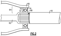
- the coupling shaft 62 is supported by a bearing assembly 64.
- the bearing assembly 64 is mounted outboard of the interface of the shaft 62 and the turbine shaft 40.
- the shaft 40 is coupled to the coupling shaft 62 through a splined interface 88.
- the shaft 40 includes splined portion 86 ( Figure 5 ) disposed about an outer surface of a portion of the shaft 40.
- the coupling shaft 62 includes an inner cavity 68 that includes a plurality of interior splines 70 ( Figure 3 and 5 ) that mate with the splined portion 86 on the shaft 40. Assembly of the shafts is provided as a tight press fit sometimes referred to as a snap fit.
- the press fit between the shaft 40 and the coupling shaft 62 is accomplished by heating the coupling shaft 62 to expand the cavity 68 that enables insertion of the splined portion 86 of the shaft 40.
- the assembly sequence for assembling the gas turbine engine requires that a bearing assembly 64 is first assembled to an outer surface of the coupling shaft 62.
- the bearing assembly 64 includes an inner race 72 that is supported on an outer surface of the coupling shaft 62.
- the bearing assembly 64 further includes an outer race 74 and a bearing 76 disposed between the inner and outer races 72, 74.
- the bearing 76 may include bearings disposed within a cage.
- the outer race 74 is in turn supported by a housing 66.
- the housing 66 supports the bearing assembly 64 that in turn supports rotation of the coupling shaft 62.
- Heating of this complex stack of parts complicates the assembly process. Heating the coupling shaft 62 causes a thermal expansion. Because the inner bearing race 72 and the outer bearing race 74 are not uniformly heated, they do not expand in a uniform manner and can induce stresses on and between the inner race 72 and the outer race 74. The non-uniform heating can induce undesired stresses on the bearing assembly.
- the example method provides steps for expanding the coupling shaft 62 to receive a portion of the turbine shaft 40 without damaging or otherwise imparting undue stresses and strains on the example bearing assembly 64.
- the temperature range is defined to provide a desired temperature differential that is does not damage the bearing assembly 64.
- the example method begins by inserting inductive coils 78 into the cavity 68 of the coupling shaft 62.
- a second set of inductive coils 80 are disposed about an outer surface of the housing 66 at an axial location that corresponds to the position of the bearing assembly 64 on the coupling shaft 62.
- a power source 82 powers the inductive coils 78, 80. It should be understood that inductive coils 78, 80 are shown by way of example, and other heating devices and structures could be utilized and are within the contemplation of this disclosure.
- the disclosed example assembly method includes the initial step of assembling the bearing assembly 64 to the outer surface of the coupling shafts 62.
- the interior inductive coil 78 is then inserted into the cavity 68 of the coupling shaft 62.
- the inner cavity 68 includes the splines 70 that mate with the corresponding splined portion 86 of the shaft 40.
- An outer or second inductive coil 80 is placed against the housing 66 at an axial location proximate to the bearing assembly 64. Application of heat with both the inner and outer inductive coils 78, 80 provides a uniform thermal expansion of the coupling shaft 62 and the bearing assembly 64.
- the second inductive coil 80 heats the housing 66 and also the outer bearing race 74 such that the coupling shaft 62, the inner bearing race 72 and the outer bearing race 74 are all expanded uniformly.
- the shaft 62 may be of a different material than the material utilized for the bearing races 72, 74 and therefore include different thermal properties. Accordingly, the specific energy and heat induced by the second conductive coil 80 may be different than the heat induced by the first inductive coil 78.
- heat imparted into the coupling shaft 62 and the inner and outer bearing races 72 and 74 is matched to provide a uniform amount of the thermal expansion that does not incur undue stresses on any of the components.
- the amount of thermal expansion is dependent on the thermal properties of each of the components and therefore the heat induced by the first coil 78 may be different than the heat induced by the second coil 80.
- the second coil 80 may impart an increased amount of heat to expand the outer race 74 in a manner that will relieve stresses and not impart undue strain on the bearings 76 that is disposed between the inner and outer races 72, 74.
- a sensor 84 is disposed proximate to the coupling shaft 62 and bearing assembly 64.
- the sensor 84 can be utilized to detect a range of expansion to determine if the coupling shaft 62 is expanded sufficiently to receive the shaft 40 or the sensor 84 may be utilized to determine when a specific temperature has been obtained by each of the components.
- a specific temperature can be correlated with a desired expansion rate and thereby determining a temperature of a specific component can provide information indicative of the amount of expansion that has occurred.
- the coupling shaft 62 is expanded to a desired diameter determined to provide for acceptance of the splined portion 86, the inductive coils 78 and 80 are removed and the spline portion 86 of the shaft 40 is inserted into the cavity 68. It should be understood that although a splined interface is disclosed, other interfaces as are known within the art are within the contemplation of this disclosure.
- the shafts 40, 62 and bearing assembly 64 are cooled such that coupling shaft constricts around the shaft 40 to form a snap or tight press fit.
- the tight press fit is desirable as it provides for a secure inner connection between the torque transferring shafts.
- the example method of assembling mating shaft components enables assembly of two shaft components in complex tolerance stack up conditions.
Landscapes
- Engineering & Computer Science (AREA)
- General Engineering & Computer Science (AREA)
- Mechanical Engineering (AREA)
- Chemical & Material Sciences (AREA)
- Combustion & Propulsion (AREA)
- Turbine Rotor Nozzle Sealing (AREA)
Priority Applications (1)
| Application Number | Priority Date | Filing Date | Title |
|---|---|---|---|
| PL17202625T PL3300834T3 (pl) | 2015-03-04 | 2016-03-04 | Sposób składania napędzającego wentylator mechanizmu przekładniowego z odciążeniem termicznym |
Applications Claiming Priority (2)
| Application Number | Priority Date | Filing Date | Title |
|---|---|---|---|
| US14/637,452 US9945424B2 (en) | 2015-03-04 | 2015-03-04 | Bearing thermal relief fan drive gear system assembly method |
| EP16158812.4A EP3064311B1 (en) | 2015-03-04 | 2016-03-04 | Bearing thermal relief fan drive gear system assembly method |
Related Parent Applications (1)
| Application Number | Title | Priority Date | Filing Date |
|---|---|---|---|
| EP16158812.4A Division EP3064311B1 (en) | 2015-03-04 | 2016-03-04 | Bearing thermal relief fan drive gear system assembly method |
Publications (2)
| Publication Number | Publication Date |
|---|---|
| EP3300834A1 EP3300834A1 (en) | 2018-04-04 |
| EP3300834B1 true EP3300834B1 (en) | 2019-05-15 |
Family
ID=55650070
Family Applications (2)
| Application Number | Title | Priority Date | Filing Date |
|---|---|---|---|
| EP17202625.4A Active EP3300834B1 (en) | 2015-03-04 | 2016-03-04 | Bearing thermal relief fan drive gear system assembly method |
| EP16158812.4A Active EP3064311B1 (en) | 2015-03-04 | 2016-03-04 | Bearing thermal relief fan drive gear system assembly method |
Family Applications After (1)
| Application Number | Title | Priority Date | Filing Date |
|---|---|---|---|
| EP16158812.4A Active EP3064311B1 (en) | 2015-03-04 | 2016-03-04 | Bearing thermal relief fan drive gear system assembly method |
Country Status (3)
| Country | Link |
|---|---|
| US (2) | US9945424B2 (pl) |
| EP (2) | EP3300834B1 (pl) |
| PL (2) | PL3300834T3 (pl) |
Families Citing this family (7)
| Publication number | Priority date | Publication date | Assignee | Title |
|---|---|---|---|---|
| GB201500700D0 (en) * | 2015-01-16 | 2015-03-04 | Rolls Royce Plc | Rolling-element bearing and method of countering load applied to rolling-element bearing |
| CN106737385B (zh) * | 2016-12-21 | 2018-05-08 | 中国南方航空工业(集团)有限公司 | 一种轴承装配方法 |
| US10710202B2 (en) | 2017-07-18 | 2020-07-14 | Raytheon Technologies Corporation | Engine component stack and assembly thereof |
| US10920592B2 (en) * | 2017-12-15 | 2021-02-16 | General Electric Company | System and method for assembling gas turbine rotor using localized inductive heating |
| US11603890B2 (en) | 2019-09-18 | 2023-03-14 | Ge Avio S.R.L. | Driveline engagement system |
| CN111927892B (zh) * | 2020-07-21 | 2021-12-07 | 江苏万基传动科技有限公司 | 一种高速轴承内外圈自动装配装置 |
| DE102023119035A1 (de) * | 2023-07-19 | 2025-01-23 | Rieter Components Germany Gmbh | Verfahren zum Demontieren und/oder Aufbereiten einer Baugruppe sowie Aufbereitungsvorrichtung |
Family Cites Families (16)
| Publication number | Priority date | Publication date | Assignee | Title |
|---|---|---|---|---|
| US3692372A (en) | 1971-06-24 | 1972-09-19 | Gen Electric | Thermally expansible bearing assembly |
| JPS604387B2 (ja) | 1976-11-01 | 1985-02-04 | トヨタ自動車株式会社 | 摩擦伝動を利用した変速機の製造方法 |
| JPS58113659A (ja) | 1981-12-26 | 1983-07-06 | Toyota Motor Corp | 自動車用歯車変速機における変速ギヤとシヤフトの固定構造 |
| US4639194A (en) | 1984-05-02 | 1987-01-27 | General Motors Corporation | Hybrid gas turbine rotor |
| US5580183A (en) * | 1994-04-29 | 1996-12-03 | United Technologies Corporation | Gas turbine engine spline arrangement |
| US7736817B2 (en) | 2003-09-30 | 2010-06-15 | Hewlett-Packard Development Company, L.P. | Method of forming an interface between components having different rates of expansion |
| US8662785B2 (en) | 2006-11-04 | 2014-03-04 | Zf Friedrichshafen Ag | Shaft-gear connection |
| WO2010037414A1 (en) | 2008-09-30 | 2010-04-08 | Aktiebolaget Skf | Bearing heater |
| DE102008021682A1 (de) | 2008-04-30 | 2009-11-05 | Magna Powertrain Ag & Co Kg | Verfahren zur Montage einer Baueinheit |
| DE102009024455A1 (de) * | 2009-06-10 | 2011-01-05 | Audi Ag | Gebautes Wellenelement, insbesondere gebaute Nockenwelle für ventilgesteuerte Brennkraftmaschinen |
| US8878933B2 (en) * | 2010-07-06 | 2014-11-04 | Motorola Solutions, Inc. | Method and apparatus for providing and determining integrity of video |
| EP2627909B1 (en) | 2010-10-13 | 2019-07-10 | The Government of the United States of America as represented by the Secretary of the Navy | Rotor assembly with thermally insulating turbine coupling |
| DE102011004530A1 (de) * | 2010-12-15 | 2012-06-21 | Mahle International Gmbh | Heizvorrichtung |
| US9022684B2 (en) | 2012-02-06 | 2015-05-05 | United Technologies Corporation | Turbine engine shaft coupling |
| US9115598B2 (en) | 2012-06-05 | 2015-08-25 | United Technologies Corporation | Front bearing support for a fan drive gear system |
| CN103769796B (zh) | 2013-10-30 | 2016-06-08 | 北车风电有限公司 | 一种兆瓦级风电机组主轴承内、外圈同时加热方法 |
-
2015
- 2015-03-04 US US14/637,452 patent/US9945424B2/en active Active
-
2016
- 2016-03-04 PL PL17202625T patent/PL3300834T3/pl unknown
- 2016-03-04 EP EP17202625.4A patent/EP3300834B1/en active Active
- 2016-03-04 PL PL16158812T patent/PL3064311T3/pl unknown
- 2016-03-04 EP EP16158812.4A patent/EP3064311B1/en active Active
-
2018
- 2018-04-17 US US15/955,022 patent/US10495151B2/en active Active
Non-Patent Citations (1)
| Title |
|---|
| None * |
Also Published As
| Publication number | Publication date |
|---|---|
| PL3300834T3 (pl) | 2019-10-31 |
| US10495151B2 (en) | 2019-12-03 |
| US9945424B2 (en) | 2018-04-17 |
| US20160258488A1 (en) | 2016-09-08 |
| EP3064311A1 (en) | 2016-09-07 |
| EP3300834A1 (en) | 2018-04-04 |
| PL3064311T3 (pl) | 2018-04-30 |
| EP3064311B1 (en) | 2017-11-22 |
| US20180238394A1 (en) | 2018-08-23 |
Similar Documents
| Publication | Publication Date | Title |
|---|---|---|
| US10495151B2 (en) | Bearing thermal relief fan drive gear system assembly method | |
| EP2809918B1 (en) | Gas turbine engine buffer system | |
| EP3428409B1 (en) | Geared turbofan with integral front support and carrier | |
| EP3348803B1 (en) | Engine mid-turbine frame transfer tube for low pressure turbine case cooling | |
| EP3126640B1 (en) | Active clearance control for gas turbine engine | |
| EP3090163B1 (en) | Compressor rim thermal management | |
| EP2888463B1 (en) | Annular turbomachine seal and heat shield | |
| EP2927433B1 (en) | Active clearance control for gas turbine engine | |
| EP4124725B1 (en) | Integrated fan case and bearing support for a gas turbine engine and method | |
| EP2984291B1 (en) | Nozzle segment for a gas turbine engine | |
| EP2986824B1 (en) | Turbine minidisk bumper for gas turbine engine | |
| EP3032030A1 (en) | Gas turbine engine shaft members and maintenance method | |
| EP3022419B1 (en) | Rounded edges for a panel of a combustor | |
| EP3080400B1 (en) | Gas turbine engine rotor and corresponding method of cooling | |
| EP3102808B1 (en) | Gas turbine engine with cooling fluid composite tube | |
| EP3068981B1 (en) | Flange relief for split casing | |
| US20260015972A1 (en) | Aircraft Heat Exchanger | |
| EP3287621B1 (en) | Heat exchanger for gas turbine engine with support damper mounting | |
| EP3744957B1 (en) | Thermal management of a shaft | |
| EP3015645B1 (en) | High pressure compressor rotor thermal conditioning using outer diameter gas extraction | |
| EP2959149B1 (en) | Gas turbine engine core utilized in both commercial and military engines | |
| EP2867497B1 (en) | Turbomachine thermal energy exchange | |
| EP3091199A1 (en) | Airfoil and corresponding vane | |
| EP3392472B1 (en) | Compressor section for a gas turbine engine, corresponding gas turbine engine and method of operating a compressor section in a gas turbine engine | |
| EP3179034B1 (en) | Multi-source turbine cooling air |
Legal Events
| Date | Code | Title | Description |
|---|---|---|---|
| PUAI | Public reference made under article 153(3) epc to a published international application that has entered the european phase |
Free format text: ORIGINAL CODE: 0009012 |
|
| STAA | Information on the status of an ep patent application or granted ep patent |
Free format text: STATUS: THE APPLICATION HAS BEEN PUBLISHED |
|
| AC | Divisional application: reference to earlier application |
Ref document number: 3064311 Country of ref document: EP Kind code of ref document: P |
|
| AK | Designated contracting states |
Kind code of ref document: A1 Designated state(s): AL AT BE BG CH CY CZ DE DK EE ES FI FR GB GR HR HU IE IS IT LI LT LU LV MC MK MT NL NO PL PT RO RS SE SI SK SM TR |
|
| STAA | Information on the status of an ep patent application or granted ep patent |
Free format text: STATUS: REQUEST FOR EXAMINATION WAS MADE |
|
| 17P | Request for examination filed |
Effective date: 20181004 |
|
| GRAP | Despatch of communication of intention to grant a patent |
Free format text: ORIGINAL CODE: EPIDOSNIGR1 |
|
| RBV | Designated contracting states (corrected) |
Designated state(s): AL AT BE BG CH CY CZ DE DK EE ES FI FR GB GR HR HU IE IS IT LI LT LU LV MC MK MT NL NO PL PT RO RS SE SI SK SM TR |
|
| STAA | Information on the status of an ep patent application or granted ep patent |
Free format text: STATUS: GRANT OF PATENT IS INTENDED |
|
| RIC1 | Information provided on ipc code assigned before grant |
Ipc: F01D 25/16 20060101ALI20181029BHEP Ipc: F16D 1/10 20060101ALI20181029BHEP Ipc: F16C 19/52 20060101ALI20181029BHEP Ipc: F16B 4/00 20060101ALN20181029BHEP Ipc: B23P 11/02 20060101AFI20181029BHEP Ipc: F16C 19/06 20060101ALN20181029BHEP Ipc: F01D 5/02 20060101ALI20181029BHEP Ipc: F02C 7/36 20060101ALI20181029BHEP Ipc: F16D 1/08 20060101ALI20181029BHEP |
|
| INTG | Intention to grant announced |
Effective date: 20181115 |
|
| GRAS | Grant fee paid |
Free format text: ORIGINAL CODE: EPIDOSNIGR3 |
|
| GRAA | (expected) grant |
Free format text: ORIGINAL CODE: 0009210 |
|
| STAA | Information on the status of an ep patent application or granted ep patent |
Free format text: STATUS: THE PATENT HAS BEEN GRANTED |
|
| AC | Divisional application: reference to earlier application |
Ref document number: 3064311 Country of ref document: EP Kind code of ref document: P |
|
| AK | Designated contracting states |
Kind code of ref document: B1 Designated state(s): AL AT BE BG CH CY CZ DE DK EE ES FI FR GB GR HR HU IE IS IT LI LT LU LV MC MK MT NL NO PL PT RO RS SE SI SK SM TR |
|
| REG | Reference to a national code |
Ref country code: CH Ref legal event code: EP |
|
| REG | Reference to a national code |
Ref country code: DE Ref legal event code: R096 Ref document number: 602016014133 Country of ref document: DE |
|
| REG | Reference to a national code |
Ref country code: IE Ref legal event code: FG4D |
|
| REG | Reference to a national code |
Ref country code: NL Ref legal event code: MP Effective date: 20190515 |
|
| REG | Reference to a national code |
Ref country code: LT Ref legal event code: MG4D |
|
| PG25 | Lapsed in a contracting state [announced via postgrant information from national office to epo] |
Ref country code: SE Free format text: LAPSE BECAUSE OF FAILURE TO SUBMIT A TRANSLATION OF THE DESCRIPTION OR TO PAY THE FEE WITHIN THE PRESCRIBED TIME-LIMIT Effective date: 20190515 Ref country code: NL Free format text: LAPSE BECAUSE OF FAILURE TO SUBMIT A TRANSLATION OF THE DESCRIPTION OR TO PAY THE FEE WITHIN THE PRESCRIBED TIME-LIMIT Effective date: 20190515 Ref country code: ES Free format text: LAPSE BECAUSE OF FAILURE TO SUBMIT A TRANSLATION OF THE DESCRIPTION OR TO PAY THE FEE WITHIN THE PRESCRIBED TIME-LIMIT Effective date: 20190515 Ref country code: LT Free format text: LAPSE BECAUSE OF FAILURE TO SUBMIT A TRANSLATION OF THE DESCRIPTION OR TO PAY THE FEE WITHIN THE PRESCRIBED TIME-LIMIT Effective date: 20190515 Ref country code: FI Free format text: LAPSE BECAUSE OF FAILURE TO SUBMIT A TRANSLATION OF THE DESCRIPTION OR TO PAY THE FEE WITHIN THE PRESCRIBED TIME-LIMIT Effective date: 20190515 Ref country code: AL Free format text: LAPSE BECAUSE OF FAILURE TO SUBMIT A TRANSLATION OF THE DESCRIPTION OR TO PAY THE FEE WITHIN THE PRESCRIBED TIME-LIMIT Effective date: 20190515 Ref country code: NO Free format text: LAPSE BECAUSE OF FAILURE TO SUBMIT A TRANSLATION OF THE DESCRIPTION OR TO PAY THE FEE WITHIN THE PRESCRIBED TIME-LIMIT Effective date: 20190815 Ref country code: HR Free format text: LAPSE BECAUSE OF FAILURE TO SUBMIT A TRANSLATION OF THE DESCRIPTION OR TO PAY THE FEE WITHIN THE PRESCRIBED TIME-LIMIT Effective date: 20190515 Ref country code: PT Free format text: LAPSE BECAUSE OF FAILURE TO SUBMIT A TRANSLATION OF THE DESCRIPTION OR TO PAY THE FEE WITHIN THE PRESCRIBED TIME-LIMIT Effective date: 20190915 |
|
| PG25 | Lapsed in a contracting state [announced via postgrant information from national office to epo] |
Ref country code: GR Free format text: LAPSE BECAUSE OF FAILURE TO SUBMIT A TRANSLATION OF THE DESCRIPTION OR TO PAY THE FEE WITHIN THE PRESCRIBED TIME-LIMIT Effective date: 20190816 Ref country code: LV Free format text: LAPSE BECAUSE OF FAILURE TO SUBMIT A TRANSLATION OF THE DESCRIPTION OR TO PAY THE FEE WITHIN THE PRESCRIBED TIME-LIMIT Effective date: 20190515 Ref country code: RS Free format text: LAPSE BECAUSE OF FAILURE TO SUBMIT A TRANSLATION OF THE DESCRIPTION OR TO PAY THE FEE WITHIN THE PRESCRIBED TIME-LIMIT Effective date: 20190515 Ref country code: BG Free format text: LAPSE BECAUSE OF FAILURE TO SUBMIT A TRANSLATION OF THE DESCRIPTION OR TO PAY THE FEE WITHIN THE PRESCRIBED TIME-LIMIT Effective date: 20190815 |
|
| REG | Reference to a national code |
Ref country code: AT Ref legal event code: MK05 Ref document number: 1132872 Country of ref document: AT Kind code of ref document: T Effective date: 20190515 |
|
| PG25 | Lapsed in a contracting state [announced via postgrant information from national office to epo] |
Ref country code: DK Free format text: LAPSE BECAUSE OF FAILURE TO SUBMIT A TRANSLATION OF THE DESCRIPTION OR TO PAY THE FEE WITHIN THE PRESCRIBED TIME-LIMIT Effective date: 20190515 Ref country code: EE Free format text: LAPSE BECAUSE OF FAILURE TO SUBMIT A TRANSLATION OF THE DESCRIPTION OR TO PAY THE FEE WITHIN THE PRESCRIBED TIME-LIMIT Effective date: 20190515 Ref country code: AT Free format text: LAPSE BECAUSE OF FAILURE TO SUBMIT A TRANSLATION OF THE DESCRIPTION OR TO PAY THE FEE WITHIN THE PRESCRIBED TIME-LIMIT Effective date: 20190515 Ref country code: CZ Free format text: LAPSE BECAUSE OF FAILURE TO SUBMIT A TRANSLATION OF THE DESCRIPTION OR TO PAY THE FEE WITHIN THE PRESCRIBED TIME-LIMIT Effective date: 20190515 Ref country code: SK Free format text: LAPSE BECAUSE OF FAILURE TO SUBMIT A TRANSLATION OF THE DESCRIPTION OR TO PAY THE FEE WITHIN THE PRESCRIBED TIME-LIMIT Effective date: 20190515 |
|
| REG | Reference to a national code |
Ref country code: DE Ref legal event code: R097 Ref document number: 602016014133 Country of ref document: DE |
|
| PG25 | Lapsed in a contracting state [announced via postgrant information from national office to epo] |
Ref country code: SM Free format text: LAPSE BECAUSE OF FAILURE TO SUBMIT A TRANSLATION OF THE DESCRIPTION OR TO PAY THE FEE WITHIN THE PRESCRIBED TIME-LIMIT Effective date: 20190515 |
|
| PLBE | No opposition filed within time limit |
Free format text: ORIGINAL CODE: 0009261 |
|
| STAA | Information on the status of an ep patent application or granted ep patent |
Free format text: STATUS: NO OPPOSITION FILED WITHIN TIME LIMIT |
|
| PG25 | Lapsed in a contracting state [announced via postgrant information from national office to epo] |
Ref country code: TR Free format text: LAPSE BECAUSE OF FAILURE TO SUBMIT A TRANSLATION OF THE DESCRIPTION OR TO PAY THE FEE WITHIN THE PRESCRIBED TIME-LIMIT Effective date: 20190515 |
|
| 26N | No opposition filed |
Effective date: 20200218 |
|
| PG25 | Lapsed in a contracting state [announced via postgrant information from national office to epo] |
Ref country code: SI Free format text: LAPSE BECAUSE OF FAILURE TO SUBMIT A TRANSLATION OF THE DESCRIPTION OR TO PAY THE FEE WITHIN THE PRESCRIBED TIME-LIMIT Effective date: 20190515 |
|
| PG25 | Lapsed in a contracting state [announced via postgrant information from national office to epo] |
Ref country code: MC Free format text: LAPSE BECAUSE OF FAILURE TO SUBMIT A TRANSLATION OF THE DESCRIPTION OR TO PAY THE FEE WITHIN THE PRESCRIBED TIME-LIMIT Effective date: 20190515 |
|
| REG | Reference to a national code |
Ref country code: CH Ref legal event code: PL |
|
| REG | Reference to a national code |
Ref country code: BE Ref legal event code: MM Effective date: 20200331 |
|
| PG25 | Lapsed in a contracting state [announced via postgrant information from national office to epo] |
Ref country code: LU Free format text: LAPSE BECAUSE OF NON-PAYMENT OF DUE FEES Effective date: 20200304 |
|
| PG25 | Lapsed in a contracting state [announced via postgrant information from national office to epo] |
Ref country code: CH Free format text: LAPSE BECAUSE OF NON-PAYMENT OF DUE FEES Effective date: 20200331 Ref country code: IE Free format text: LAPSE BECAUSE OF NON-PAYMENT OF DUE FEES Effective date: 20200304 Ref country code: LI Free format text: LAPSE BECAUSE OF NON-PAYMENT OF DUE FEES Effective date: 20200331 |
|
| PG25 | Lapsed in a contracting state [announced via postgrant information from national office to epo] |
Ref country code: BE Free format text: LAPSE BECAUSE OF NON-PAYMENT OF DUE FEES Effective date: 20200331 |
|
| PG25 | Lapsed in a contracting state [announced via postgrant information from national office to epo] |
Ref country code: MT Free format text: LAPSE BECAUSE OF FAILURE TO SUBMIT A TRANSLATION OF THE DESCRIPTION OR TO PAY THE FEE WITHIN THE PRESCRIBED TIME-LIMIT Effective date: 20190515 Ref country code: CY Free format text: LAPSE BECAUSE OF FAILURE TO SUBMIT A TRANSLATION OF THE DESCRIPTION OR TO PAY THE FEE WITHIN THE PRESCRIBED TIME-LIMIT Effective date: 20190515 |
|
| PG25 | Lapsed in a contracting state [announced via postgrant information from national office to epo] |
Ref country code: RO Free format text: LAPSE BECAUSE OF FAILURE TO SUBMIT A TRANSLATION OF THE DESCRIPTION OR TO PAY THE FEE WITHIN THE PRESCRIBED TIME-LIMIT Effective date: 20190515 Ref country code: MK Free format text: LAPSE BECAUSE OF FAILURE TO SUBMIT A TRANSLATION OF THE DESCRIPTION OR TO PAY THE FEE WITHIN THE PRESCRIBED TIME-LIMIT Effective date: 20190515 Ref country code: IS Free format text: LAPSE BECAUSE OF FAILURE TO SUBMIT A TRANSLATION OF THE DESCRIPTION OR TO PAY THE FEE WITHIN THE PRESCRIBED TIME-LIMIT Effective date: 20190915 |
|
| REG | Reference to a national code |
Ref country code: DE Ref legal event code: R081 Ref document number: 602016014133 Country of ref document: DE Owner name: RAYTHEON TECHNOLOGIES CORPORATION (N.D.GES.D.S, US Free format text: FORMER OWNER: UNITED TECHNOLOGIES CORPORATION, FARMINGTON, CONN., US Ref country code: DE Ref legal event code: R081 Ref document number: 602016014133 Country of ref document: DE Owner name: RTX CORPORATION (N.D.GES.D. STAATES DELAWARE),, US Free format text: FORMER OWNER: UNITED TECHNOLOGIES CORPORATION, FARMINGTON, CONN., US |
|
| P01 | Opt-out of the competence of the unified patent court (upc) registered |
Effective date: 20230520 |
|
| REG | Reference to a national code |
Ref country code: DE Ref legal event code: R081 Ref document number: 602016014133 Country of ref document: DE Owner name: RTX CORPORATION (N.D.GES.D. STAATES DELAWARE),, US Free format text: FORMER OWNER: RAYTHEON TECHNOLOGIES CORPORATION (N.D.GES.D.STAATES DELAWARE), ARLINGTON, VA, US |
|
| PGFP | Annual fee paid to national office [announced via postgrant information from national office to epo] |
Ref country code: GB Payment date: 20260220 Year of fee payment: 11 |
|
| PGFP | Annual fee paid to national office [announced via postgrant information from national office to epo] |
Ref country code: DE Payment date: 20260219 Year of fee payment: 11 |
|
| PGFP | Annual fee paid to national office [announced via postgrant information from national office to epo] |
Ref country code: IT Payment date: 20260219 Year of fee payment: 11 |
|
| PGFP | Annual fee paid to national office [announced via postgrant information from national office to epo] |
Ref country code: FR Payment date: 20260220 Year of fee payment: 11 |
|
| PGFP | Annual fee paid to national office [announced via postgrant information from national office to epo] |
Ref country code: PL Payment date: 20260220 Year of fee payment: 11 |