EP2809918B1 - Gas turbine engine buffer system - Google Patents
Gas turbine engine buffer system Download PDFInfo
- Publication number
- EP2809918B1 EP2809918B1 EP13774935.4A EP13774935A EP2809918B1 EP 2809918 B1 EP2809918 B1 EP 2809918B1 EP 13774935 A EP13774935 A EP 13774935A EP 2809918 B1 EP2809918 B1 EP 2809918B1
- Authority
- EP
- European Patent Office
- Prior art keywords
- gas turbine
- buffer
- shaft
- cooling air
- turbine engine
- Prior art date
- Legal status (The legal status is an assumption and is not a legal conclusion. Google has not performed a legal analysis and makes no representation as to the accuracy of the status listed.)
- Active
Links
- 239000007853 buffer solution Substances 0.000 title claims description 23
- 239000000872 buffer Substances 0.000 claims description 47
- 238000001816 cooling Methods 0.000 claims description 47
- 230000003750 conditioning effect Effects 0.000 claims description 15
- 238000004891 communication Methods 0.000 claims description 9
- 238000000034 method Methods 0.000 claims description 7
- 239000012530 fluid Substances 0.000 claims description 5
- 239000007789 gas Substances 0.000 description 51
- 239000000446 fuel Substances 0.000 description 5
- 239000000567 combustion gas Substances 0.000 description 4
- 239000000314 lubricant Substances 0.000 description 4
- 239000000463 material Substances 0.000 description 4
- 230000004323 axial length Effects 0.000 description 3
- 230000003068 static effect Effects 0.000 description 3
- 238000009423 ventilation Methods 0.000 description 3
- 238000011144 upstream manufacturing Methods 0.000 description 2
- 229910000831 Steel Inorganic materials 0.000 description 1
- 239000000956 alloy Substances 0.000 description 1
- 229910045601 alloy Inorganic materials 0.000 description 1
- 230000003139 buffering effect Effects 0.000 description 1
- 230000006835 compression Effects 0.000 description 1
- 238000007906 compression Methods 0.000 description 1
- 238000010276 construction Methods 0.000 description 1
- 239000002826 coolant Substances 0.000 description 1
- 238000012937 correction Methods 0.000 description 1
- 239000000284 extract Substances 0.000 description 1
- 230000001050 lubricating effect Effects 0.000 description 1
- 238000004519 manufacturing process Methods 0.000 description 1
- 238000012986 modification Methods 0.000 description 1
- 230000004048 modification Effects 0.000 description 1
- 239000010935 stainless steel Substances 0.000 description 1
- 229910001220 stainless steel Inorganic materials 0.000 description 1
- 239000010959 steel Substances 0.000 description 1
- 238000012546 transfer Methods 0.000 description 1
- 230000001052 transient effect Effects 0.000 description 1
Images


Classifications
-
- F—MECHANICAL ENGINEERING; LIGHTING; HEATING; WEAPONS; BLASTING
- F02—COMBUSTION ENGINES; HOT-GAS OR COMBUSTION-PRODUCT ENGINE PLANTS
- F02C—GAS-TURBINE PLANTS; AIR INTAKES FOR JET-PROPULSION PLANTS; CONTROLLING FUEL SUPPLY IN AIR-BREATHING JET-PROPULSION PLANTS
- F02C6/00—Plural gas-turbine plants; Combinations of gas-turbine plants with other apparatus; Adaptations of gas- turbine plants for special use
- F02C6/04—Gas-turbine plants providing heated or pressurised working fluid for other apparatus, e.g. without mechanical power output
- F02C6/06—Gas-turbine plants providing heated or pressurised working fluid for other apparatus, e.g. without mechanical power output providing compressed gas
- F02C6/08—Gas-turbine plants providing heated or pressurised working fluid for other apparatus, e.g. without mechanical power output providing compressed gas the gas being bled from the gas-turbine compressor
-
- F—MECHANICAL ENGINEERING; LIGHTING; HEATING; WEAPONS; BLASTING
- F01—MACHINES OR ENGINES IN GENERAL; ENGINE PLANTS IN GENERAL; STEAM ENGINES
- F01D—NON-POSITIVE DISPLACEMENT MACHINES OR ENGINES, e.g. STEAM TURBINES
- F01D11/00—Preventing or minimising internal leakage of working-fluid, e.g. between stages
- F01D11/02—Preventing or minimising internal leakage of working-fluid, e.g. between stages by non-contact sealings, e.g. of labyrinth type
- F01D11/04—Preventing or minimising internal leakage of working-fluid, e.g. between stages by non-contact sealings, e.g. of labyrinth type using sealing fluid, e.g. steam
-
- F—MECHANICAL ENGINEERING; LIGHTING; HEATING; WEAPONS; BLASTING
- F01—MACHINES OR ENGINES IN GENERAL; ENGINE PLANTS IN GENERAL; STEAM ENGINES
- F01D—NON-POSITIVE DISPLACEMENT MACHINES OR ENGINES, e.g. STEAM TURBINES
- F01D25/00—Component parts, details, or accessories, not provided for in, or of interest apart from, other groups
- F01D25/08—Cooling; Heating; Heat-insulation
- F01D25/12—Cooling
- F01D25/125—Cooling of bearings
-
- F—MECHANICAL ENGINEERING; LIGHTING; HEATING; WEAPONS; BLASTING
- F01—MACHINES OR ENGINES IN GENERAL; ENGINE PLANTS IN GENERAL; STEAM ENGINES
- F01D—NON-POSITIVE DISPLACEMENT MACHINES OR ENGINES, e.g. STEAM TURBINES
- F01D25/00—Component parts, details, or accessories, not provided for in, or of interest apart from, other groups
- F01D25/16—Arrangement of bearings; Supporting or mounting bearings in casings
-
- F—MECHANICAL ENGINEERING; LIGHTING; HEATING; WEAPONS; BLASTING
- F02—COMBUSTION ENGINES; HOT-GAS OR COMBUSTION-PRODUCT ENGINE PLANTS
- F02C—GAS-TURBINE PLANTS; AIR INTAKES FOR JET-PROPULSION PLANTS; CONTROLLING FUEL SUPPLY IN AIR-BREATHING JET-PROPULSION PLANTS
- F02C7/00—Features, components parts, details or accessories, not provided for in, or of interest apart form groups F02C1/00 - F02C6/00; Air intakes for jet-propulsion plants
- F02C7/06—Arrangements of bearings; Lubricating
-
- F—MECHANICAL ENGINEERING; LIGHTING; HEATING; WEAPONS; BLASTING
- F02—COMBUSTION ENGINES; HOT-GAS OR COMBUSTION-PRODUCT ENGINE PLANTS
- F02C—GAS-TURBINE PLANTS; AIR INTAKES FOR JET-PROPULSION PLANTS; CONTROLLING FUEL SUPPLY IN AIR-BREATHING JET-PROPULSION PLANTS
- F02C7/00—Features, components parts, details or accessories, not provided for in, or of interest apart form groups F02C1/00 - F02C6/00; Air intakes for jet-propulsion plants
- F02C7/12—Cooling of plants
- F02C7/16—Cooling of plants characterised by cooling medium
- F02C7/18—Cooling of plants characterised by cooling medium the medium being gaseous, e.g. air
- F02C7/185—Cooling means for reducing the temperature of the cooling air or gas
-
- F—MECHANICAL ENGINEERING; LIGHTING; HEATING; WEAPONS; BLASTING
- F02—COMBUSTION ENGINES; HOT-GAS OR COMBUSTION-PRODUCT ENGINE PLANTS
- F02C—GAS-TURBINE PLANTS; AIR INTAKES FOR JET-PROPULSION PLANTS; CONTROLLING FUEL SUPPLY IN AIR-BREATHING JET-PROPULSION PLANTS
- F02C7/00—Features, components parts, details or accessories, not provided for in, or of interest apart form groups F02C1/00 - F02C6/00; Air intakes for jet-propulsion plants
- F02C7/28—Arrangement of seals
-
- F—MECHANICAL ENGINEERING; LIGHTING; HEATING; WEAPONS; BLASTING
- F02—COMBUSTION ENGINES; HOT-GAS OR COMBUSTION-PRODUCT ENGINE PLANTS
- F02C—GAS-TURBINE PLANTS; AIR INTAKES FOR JET-PROPULSION PLANTS; CONTROLLING FUEL SUPPLY IN AIR-BREATHING JET-PROPULSION PLANTS
- F02C9/00—Controlling gas-turbine plants; Controlling fuel supply in air- breathing jet-propulsion plants
- F02C9/16—Control of working fluid flow
- F02C9/18—Control of working fluid flow by bleeding, bypassing or acting on variable working fluid interconnections between turbines or compressors or their stages
-
- F—MECHANICAL ENGINEERING; LIGHTING; HEATING; WEAPONS; BLASTING
- F05—INDEXING SCHEMES RELATING TO ENGINES OR PUMPS IN VARIOUS SUBCLASSES OF CLASSES F01-F04
- F05D—INDEXING SCHEME FOR ASPECTS RELATING TO NON-POSITIVE-DISPLACEMENT MACHINES OR ENGINES, GAS-TURBINES OR JET-PROPULSION PLANTS
- F05D2260/00—Function
- F05D2260/20—Heat transfer, e.g. cooling
- F05D2260/202—Heat transfer, e.g. cooling by film cooling
-
- F—MECHANICAL ENGINEERING; LIGHTING; HEATING; WEAPONS; BLASTING
- F05—INDEXING SCHEMES RELATING TO ENGINES OR PUMPS IN VARIOUS SUBCLASSES OF CLASSES F01-F04
- F05D—INDEXING SCHEME FOR ASPECTS RELATING TO NON-POSITIVE-DISPLACEMENT MACHINES OR ENGINES, GAS-TURBINES OR JET-PROPULSION PLANTS
- F05D2260/00—Function
- F05D2260/20—Heat transfer, e.g. cooling
- F05D2260/213—Heat transfer, e.g. cooling by the provision of a heat exchanger within the cooling circuit
-
- Y—GENERAL TAGGING OF NEW TECHNOLOGICAL DEVELOPMENTS; GENERAL TAGGING OF CROSS-SECTIONAL TECHNOLOGIES SPANNING OVER SEVERAL SECTIONS OF THE IPC; TECHNICAL SUBJECTS COVERED BY FORMER USPC CROSS-REFERENCE ART COLLECTIONS [XRACs] AND DIGESTS
- Y02—TECHNOLOGIES OR APPLICATIONS FOR MITIGATION OR ADAPTATION AGAINST CLIMATE CHANGE
- Y02T—CLIMATE CHANGE MITIGATION TECHNOLOGIES RELATED TO TRANSPORTATION
- Y02T50/00—Aeronautics or air transport
- Y02T50/60—Efficient propulsion technologies, e.g. for aircraft
Definitions
- This disclosure relates to a gas turbine engine, and more particularly to a buffer system that can provide buffer cooling air to cool portions of the gas turbine engine, including at least one shaft of the gas turbine engine.
- Gas turbine engines typically include at least a compressor section, a combustor section and a turbine section. During operation, air is pressurized in the compressor section and is mixed with fuel and burned in the combustor section to generate hot combustion gases. The hot combustion gases are communicated through the turbine section which extracts energy from the hot combustion gases to power the compressor section and other gas turbine engine modes.
- Gas turbine engines typically include shafts that support a plurality of airfoil supporting rotors of the compressor section and the turbine section.
- an inner shaft i.e., a low speed shaft
- an outer shaft i.e., a high speed shaft
- These shafts, in particular the inner shaft can be exposed to relatively high torque loading and stresses that result from size limitations caused by the need for the shaft to traverse the rotor structure inboard of the radially inner disk bores.
- GB 1,095,129 A and FR1446066 describe cooling and seal pressurising systems for gas turbine engines.
- US 2003/0046938 A1 describes apparatus and methods for controlling flow in turbomachinery.
- US 2,584,899 describes the construction of stator elements of turbines, compressors or similar machines.
- the present invention relates to a gas turbine as laid out in claim 1.
- the outer shaft can include a tie shaft.
- the buffer cooling air can be communicated axially along an outer diameter of the inner shaft.
- the buffer system can include a controller that selectively operates the conditioning device.
- the gas turbine engine includes a compressor section, a combustor in fluid communication with the compressor section, a turbine section in fluid communication with the combustor, the inner and outer shaft that interconnect the portion of the compressor section and the turbine section, and a bearing structure that supports the inner or outer shaft.
- the bearing structure can include a bearing compartment.
- a buffer system can selectively communicate a buffer cooling air to the bearing structure and axially along the inner or outer shaft.
- the conditioning device can include either a heat exchanger or an ejector.
- the gas turbine engine can include a high bypass geared aircraft engine having a bypass ratio of greater than about six (6).
- the gas turbine engine includes a low fan pressure ratio of less than about 1.45.
- the present invention relates also to a method as laid out in claim 6.
- the step of communicating the buffer cooling air axially along at least a portion of the inner shaft can include communicating the buffer cooling air along an outer diameter of the inner shaft.
- the step of communicating the buffer cooling air axially along at least a portion of the inner shaft can include communicating the buffer cooling air along each of an inner diameter and an outer diameter of the inner shaft.
- Figure 1 is a cross-section of a gas turbine engine 20.
- the gas turbine engine 20 of this example is a two-spool turbofan engine that generally incorporates a fan section 22, a compressor section 24, a combustor section 26 and a turbine section 28.
- Alternative engines might include an augmenter section (not shown) among other systems or features.
- the fan section 22 drives air along a bypass flow path while the compressor section 24 drives air along a core flow path for compression and communication into the combustor section 26.
- the hot combustion gases generated in the combustor section 26 are expanded through the turbine section 28.
- turbofan gas turbine engine Although depicted as a turbofan gas turbine engine in the disclosed non-limiting embodiment, it should be understood that the concepts described herein are not limited to turbofan engines and these teachings could extend to other types of turbine engines, including but not limited to three-spool engine architectures and land based engines.
- the gas turbine engine 20 generally includes a low speed spool 30 and a high speed spool 32 mounted for rotation about an engine centerline longitudinal axis A relative to an engine static structure 36 via several bearing structures 38. It should be understood that various bearing structures 38 at various locations may alternatively or additionally be provided.
- the low speed spool 30 generally includes an inner shaft 40 (i.e., a low shaft) that interconnects a fan 42, a low pressure compressor 44 and a low pressure turbine 46.
- the inner shaft 40 can be connected to the fan 42 through a geared architecture 48 to drive the fan 42 at a lower speed than the low speed spool 30.
- the high speed spool 32 includes an outer shaft 50 (i.e., a high shaft) that interconnects a high pressure compressor 52 and a high pressure turbine 54.
- the inner shaft 40 and the outer shaft 50 are supported at a plurality of axial locations by bearing structures 38 that are positioned within the engine static structure 36.
- a combustor 56 is arranged between the high pressure compressor 52 and the high pressure turbine 54.
- a mid-turbine frame 57 of the engine static structure 36 is arranged generally between the high pressure turbine 54 and the low pressure turbine 46.
- the mid-turbine frame 57 can support one or more bearing structures 38 in the turbine section 28.
- the inner shaft 40 and the outer shaft 50 are concentric and rotate via the bearing structures 38 about the engine centerline longitudinal axis A, which is collinear with their longitudinal axes.
- the inner shaft 40 and the outer shaft 50 can be either co-rotating or counter-rotating with respect to one another.
- the core airflow is compressed by the low pressure compressor 44 and the high pressure compressor 52, is mixed with fuel and burned in the combustor 56, and is then expanded over the high pressure turbine 54 and the low pressure turbine 46.
- the mid-turbine frame 57 includes airfoils 59 which are in the core airflow path.
- the high pressure turbine 54 and the low pressure turbine 46 rotationally drive the respective low speed spool 30 and the high speed spool 32 in response to the expansion.
- the gas turbine engine 20 is a high-bypass geared aircraft engine.
- the gas turbine engine 20 bypass ratio is greater than about six (6:1).
- the geared architecture 48 of the example gas turbine engine 20 includes an epicyclic gear train, such as a planetary gear system or other gear system.
- the example epicyclic gear train has a gear reduction ratio of greater than about 2.3.
- the geared architecture 48 enables operation of the low speed spool 30 at higher speeds which can increase the operational efficiency of the low pressure compressor 44 and low pressure turbine 46 and render increased pressure in a fewer number of stages.
- the low pressure turbine 46 pressure ratio is pressure measured prior to inlet of low pressure turbine 46 as related to the pressure at the outlet of the low pressure turbine 46 of the gas turbine engine 20.
- the bypass ratio of the gas turbine engine 20 is greater than about ten (10:1)
- the fan diameter is significantly larger than that of the low pressure compressor 44
- the low pressure turbine 46 has a pressure ratio that is greater than about 5 (5:1).
- the geared architecture 48 of yet another embodiment is an epicyclic gear train with a gear reduction ratio of greater than about 2.5:1. It should be understood, however, that the above parameters are only exemplary of one embodiment of a geared architecture engine and that the present disclosure is applicable to other gas turbine engines including direct drive turbofans.
- a significant amount of thrust is provided by a bypass flow B due to the high bypass ratio.
- the fan section 22 of the gas turbine engine 20 is designed for a particular flight conditiontypically cruise at about 0.8 Mach and about 10500 meters (35,000 feet). This flight condition, with the gas turbine engine 20 at its best fuel consumption, is also known as bucket cruise.
- TSFC Thirust Specific Fuel Consumption
- Fan Pressure Ratio is the pressure ratio across the fan section 22 without the use of a Fan Exit Guide Vane system.
- the low Fan Pressure Ratio according to one non-limiting embodiment of the example gas turbine engine 20 is less than 1.45.
- Low Corrected Fan Tip Speed is the actual fan tip speed divided by an industry standard temperature correction of "T" / 518.7 0.5 .
- T represents the ambient temperature in degrees Rankine.
- the Low Corrected Fan Tip Speed according to one non-limiting embodiment of the example gas turbine engine 20 is less than about 1150 fps (351 m/s).
- Figure 2 illustrates a portion 100 of a gas turbine engine, such as the gas turbine engine 20.
- the portion 100 can include one or more bearing structures 38. Only one bearing structure 38 is depicted in Figure 2 to schematically illustrate its features, but this is in no way intended to limit this disclosure.
- the bearing structure 38 supports a shaft 61, such as the outer shaft 50, which supports a rotor assembly 63, such as a rotor assembly of the compressor section 24 or the turbine section 28, through a hub 65.
- the shaft 61 is a tie shaft that that connects the high pressure compressor 52 to the high pressure turbine 54.
- the rotor assembly 63 carries at least one airfoil 67 for adding or extracting energy from the core airflow.
- the bearing structure 38 defines a bearing compartment B that houses one or more bearings 71.
- the bearing compartment B contains a lubricant for lubricating (and acting as a cooling medium to) the bearings 71.
- One or more seals 73 (two shown) contain the lubricant within the bearing compartment B.
- the seals 73 of the bearing compartment B must be pressurized to prevent the lubricant from leaking out during certain flight conditions, both steady state and transient.
- a buffer system can be used to communicate buffer supply air to the bearing compartment B in order to provide adequate pressurization of the seals 73 without exceeding material and/or lubricant temperature limitations.
- Example buffer systems that can be used for this and other purposes, including cooling at least one shaft, are detailed below.
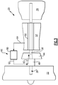
- Figure 3 illustrates an example buffer system 60 that can communicate a buffer cooling air 62 to a first portion of the gas turbine engine 20, such one or more bearing structures 38 (shown schematically in Figure 3 ) and a second portion of the gas turbine engine 20, such as to the inner shaft 40 (shown schematically in Figure 4 ) of the gas turbine engine 20.
- the buffer cooling air 62 pressurizes the outside of the bearing compartment(s) of the bearing structure(s) 38 to maintain sufficient pressure differential between the buffer cavity and the inner bearing compartment cavity and maintain bearing compartment seal leakage inflow at an acceptable temperature.
- the buffer cooling air 62 can also be used to cool the inner shaft 40 (and optionally the outer shaft 50, see Figure 1 ) to acceptable operating temperatures.
- the inner and outer shafts 40, 50 can be manufactured using relatively low temperature capable materials rather than exotic, high cost, and difficult to manufacture alloys.
- Example low temperature capable materials include steel or stainless steel among other known materials.
- the buffer system 60 of Figure 3 may include a bleed air supply 64 and a conditioning device 80.
- the bleed air supply 64 may be sourced from the fan section 22, the low pressure compressor 44 or the high pressure compressor 52. In the illustrated non-limiting example, the bleed air supply 64 is sourced from a middle stage of the high pressure compressor 52.
- the conditioning device 80 can cool and/or otherwise condition the bleed air supply 64 to render a buffer cooling air 62 having an acceptable temperature for buffering the environment surrounding the bearing structures 38 and the inner shaft 40.
- the conditioning device 80 could include an air-to-air heat exchanger, a fuel-to-air heat exchanger, or any other suitable heater exchanger.
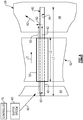
- the buffer cooling air 62 may be communicated from the conditioning device 80 to a bearing structure 38, then axially along an outer diameter 82 of the inner shaft 40 (i.e., between the inner shaft 40 and the outer shaft 50), and then downstream to the turbine section 28 to cool other bearing structures or for turbine ventilation purposes.
- the outer shaft 50 which in this example is a tie shaft that interconnects the high pressure compressor 52 and the high pressure turbine 54, isolates the inner shaft 40 from potentially hotter compressor ventilation airflow C supplied from the same or different source.
- the compressor ventilation airflow C may be hotter than the inner shaft 40 as a result of heat transfer with the hardware of the compressor section 24.
- the buffer cooling air 62 may also be simultaneously communicated axially along and through an inner diameter 84 of the inner shaft 40 where the inner shaft 40 is hollow. It should be understood that the buffer cooling air 62 may be communicated along the outer diameter 82, along the inner diameter 84, or both at the same time. The buffer cooling air 62 may condition the bearing structures 38 and the inner and outer shafts 40, 50 as it is communicated along this path. In this example, the buffer cooling air 62 is communicated substantially along an entire axial length L1 of the inner shaft 40 and an entire axial length L2 of the outer shaft 50. However, the buffer cooling air 62 could be communicated along only portions of the axial lengths L1, L2 depending on how and where the buffer cooling air 62 is piped to the inner shaft 40 and the outer shaft 50.
- the buffer cooling air 62 is communicated between the conditioning device 80, the bearing structures 38 and the inner and outer shafts 40, 50 via buffer tubing, conduits, or other passageways.
- Such tubing, conduits and/or passageways could be routed throughout the gas turbine engine 20. The type, location and configuration of such tubing, conduits and/or passageways are not intended to limit this disclosure.
- the buffer system 60 may also include a controller 70.
- the controller 70 can be programmed to selectively command the communication of buffer cooling air 62 during certain operating conditions.
- the controller 70 may also potentially generate a signal to command operation of the conditioning device 80 and/or a source-switching valve. Also, although shown as a separate feature, the controller functionality could be incorporated into the conditioning device 80.
- the buffer system 60 is operable to communicate buffer cooling air 162 for responding to any engine operating condition.
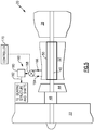
- Figure 5 illustrates another example buffer system 160 that may be used to supply a buffer cooling air 162 to pressurize a bearing structure 38 and cool the inner and outer shafts 40, 50 of the gas turbine engine 20.
- the buffer system 160 is a multi-source buffer system that includes a first bleed air supply 164 and a second bleed air supply 166.
- the first bleed air supply 164 is a low pressure bleed air supply
- the second bleed air supply 166 is a high pressure bleed air supply that includes a pressure that is greater than the pressure of the first bleed air supply 164.
- the first bleed air supply 164 may be sourced from the fan section 22, the low pressure compressor 44 or the high pressure compressor 52. In the illustrated non-limiting example, the first bleed air supply 164 is sourced from an upstream stage of the high pressure compressor 52. However, the first bleed air supply 164 could be sourced from any location that is upstream from the second bleed air supply 166.
- the second bleed air supply 166 may be sourced from the high pressure compressor 52, such as from a middle or downstream stage of the high pressure compressor 52. The second bleed air supply 166 could also be sourced from the low pressure compressor 44 or the fan section 22 depending on where the first bleed air supply 164 is sourced from.
- the buffer system 160 may also include a valve 168 that is in communication with both the first bleed air supply 164 and the second bleed air supply 166. Although shown schematically, the first bleed air supply 164 and the second bleed air supply 166 can be in fluid communication with the valve 168 via buffer tubing, conduits, or other passageways.
- the valve 168 may select between the first bleed air supply 164 and the second bleed air supply 166 to communicate a buffer cooling air 162 having a desired temperature and pressure to desired portions of the gas turbine engine 20.
- the valve 168 communicates either the first bleed air supply 164 or the second bleed air supply 168 to a conditioning device 180 to cool the air supply and render the buffer cooling air 162.
- the valve 168 can be a passive valve or a controller base valve.
- a passive valve operates like a pressure regulator that can switch between two or more sources without being commanded to do so by a controller, such as an engine control (EEC).
- EEC engine control
- the valve 168 of this example uses only a single input which is directly measured to switch between the first bleed air supply 164 and the second bleed air supply 661.
- the valve 168 could also be a controller based valve.
- the buffer system 160 could include a controller 170 in communication with the valve 168 for selecting between the first bleed air supply 164 and the second bleed air supply 166.
- the controller 170 is programmed with the necessary logic for selecting between the first bleed air supply 164 and the second bleed air supply 166 in response to detecting a pre-defined power condition of the gas turbine engine 20.
- the controller 170 could also be programmed with multiple inputs.
- the determination of whether to communicate the first bleed air supply 164 or the second bleed air supply 166 as the buffer cooling air 162 is based on a power condition of the gas turbine engine 20.
- the term "power condition" as used in this disclosure generally refers to an operability condition of the gas turbine engine 20.
- Gas turbine engine power conditions can include low power conditions and high power conditions.
- Example low power conditions include, but are not limited to, ground operation, ground idle and descent idle.
- Example high power conditions include, but are not limited to, takeoff, climb, and cruise conditions. It should be understood that other power conditions are also contemplated as within the scope of this disclosure.
- the valve 168 communicates the first bleed air supply 164 (which is a relatively lower pressure bleed air supply) to the conditioning device 180 in response to identifying a high power condition of a gas turbine engine 20.
- the second bleed air supply 166 (which is a relatively higher pressure bleed air supply) is selected by the valve 168 and communicated to the conditioning device 180 in response to detecting a low power condition of the gas turbine engine 20.
- Both sources of bleed air are intended to maintain the same minimum pressure delta across the bearing compartment seals. Low power conditions require a higher pressure stage source to maintain adequate pressure differential, while high power conditions can meet requirements with a lower stage pressure source. Use of the lowest possible compressor stage can to meet the pressure requirements and minimize supply temperature and any negative performance impact to the gas turbine engine 20.
- the conditioning device 180 of the buffer system 160 could include a heat exchanger or an ejector.
- An ejector adds pressure (using a small amount of the second bleed air supply 166) to the first bleed air supply 164 to prepare the buffer supply air 162.
Description
- This disclosure relates to a gas turbine engine, and more particularly to a buffer system that can provide buffer cooling air to cool portions of the gas turbine engine, including at least one shaft of the gas turbine engine.
- Gas turbine engines typically include at least a compressor section, a combustor section and a turbine section. During operation, air is pressurized in the compressor section and is mixed with fuel and burned in the combustor section to generate hot combustion gases. The hot combustion gases are communicated through the turbine section which extracts energy from the hot combustion gases to power the compressor section and other gas turbine engine modes.
- Gas turbine engines typically include shafts that support a plurality of airfoil supporting rotors of the compressor section and the turbine section. For example, in a two-spool turbofan engine, an inner shaft (i.e., a low speed shaft) and an outer shaft (i.e., a high speed shaft) can be incorporated. These shafts, in particular the inner shaft, can be exposed to relatively high torque loading and stresses that result from size limitations caused by the need for the shaft to traverse the rotor structure inboard of the radially inner disk bores.
-
GB 1,095,129 A FR1446066 US 2003/0046938 A1 describes apparatus and methods for controlling flow in turbomachinery.US 2,584,899 describes the construction of stator elements of turbines, compressors or similar machines. - The present invention relates to a gas turbine as laid out in claim 1.
- In a further embodiment of the foregoing gas turbine engine embodiment, the outer shaft can include a tie shaft.
- In a further embodiment of any of the foregoing gas turbine engine embodiments, the buffer cooling air can be communicated axially along an outer diameter of the inner shaft.
- In a further embodiment of any of the foregoing gas turbine engine embodiments, the buffer system can include a controller that selectively operates the conditioning device.
- In a further embodiment of any of the foregoing gas turbine engine embodiments, the gas turbine engine includes a compressor section, a combustor in fluid communication with the compressor section, a turbine section in fluid communication with the combustor, the inner and outer shaft that interconnect the portion of the compressor section and the turbine section, and a bearing structure that supports the inner or outer shaft. The bearing structure can include a bearing compartment. A buffer system can selectively communicate a buffer cooling air to the bearing structure and axially along the inner or outer shaft.
- In a further embodiment of any of the foregoing gas turbine engine embodiments, the conditioning device can include either a heat exchanger or an ejector.
- In a further embodiment of any of the foregoing gas turbine engine embodiments, the gas turbine engine can include a high bypass geared aircraft engine having a bypass ratio of greater than about six (6).
- In a further embodiment of any of the foregoing gas turbine engine embodiments, the gas turbine engine includes a low fan pressure ratio of less than about 1.45.
- The present invention relates also to a method as laid out in claim 6.
- In a further embodiment of the foregoing method embodiment, the step of communicating the buffer cooling air axially along at least a portion of the inner shaft can include communicating the buffer cooling air along an outer diameter of the inner shaft.
- In a further embodiment of any of the foregoing method embodiments, the step of communicating the buffer cooling air axially along at least a portion of the inner shaft can include communicating the buffer cooling air along each of an inner diameter and an outer diameter of the inner shaft.
- The various features and advantages of this disclosure will become apparent to those skilled in the art from the following detailed description. The drawings that accompany the detailed description can be briefly described as follows.
-
-
Figure 1 is a cross-section of a gas turbine engine. -
Figure 2 is a schematic cross-section a gas turbine engine. -
Figure 3 is a schematic of an example buffer system of the gas turbine engine. -
Figure 4 illustrates additional aspects of the buffer system ofFigure 3 . -
Figure 5 is a schematic of another example of a buffer system. -
Figure 1 is a cross-section of agas turbine engine 20. Thegas turbine engine 20 of this example is a two-spool turbofan engine that generally incorporates afan section 22, acompressor section 24, acombustor section 26 and aturbine section 28. Alternative engines might include an augmenter section (not shown) among other systems or features. Thefan section 22 drives air along a bypass flow path while thecompressor section 24 drives air along a core flow path for compression and communication into thecombustor section 26. The hot combustion gases generated in thecombustor section 26 are expanded through theturbine section 28. Although depicted as a turbofan gas turbine engine in the disclosed non-limiting embodiment, it should be understood that the concepts described herein are not limited to turbofan engines and these teachings could extend to other types of turbine engines, including but not limited to three-spool engine architectures and land based engines. - The
gas turbine engine 20 generally includes alow speed spool 30 and ahigh speed spool 32 mounted for rotation about an engine centerline longitudinal axis A relative to an enginestatic structure 36 viaseveral bearing structures 38. It should be understood thatvarious bearing structures 38 at various locations may alternatively or additionally be provided. - The
low speed spool 30 generally includes an inner shaft 40 (i.e., a low shaft) that interconnects afan 42, alow pressure compressor 44 and alow pressure turbine 46. Theinner shaft 40 can be connected to thefan 42 through a gearedarchitecture 48 to drive thefan 42 at a lower speed than thelow speed spool 30. Thehigh speed spool 32 includes an outer shaft 50 (i.e., a high shaft) that interconnects ahigh pressure compressor 52 and ahigh pressure turbine 54. In this example, theinner shaft 40 and theouter shaft 50 are supported at a plurality of axial locations bybearing structures 38 that are positioned within the enginestatic structure 36. - A
combustor 56 is arranged between thehigh pressure compressor 52 and thehigh pressure turbine 54. Amid-turbine frame 57 of the enginestatic structure 36 is arranged generally between thehigh pressure turbine 54 and thelow pressure turbine 46. Themid-turbine frame 57 can support one or more bearingstructures 38 in theturbine section 28. Theinner shaft 40 and theouter shaft 50 are concentric and rotate via thebearing structures 38 about the engine centerline longitudinal axis A, which is collinear with their longitudinal axes. Theinner shaft 40 and theouter shaft 50 can be either co-rotating or counter-rotating with respect to one another. - The core airflow is compressed by the
low pressure compressor 44 and thehigh pressure compressor 52, is mixed with fuel and burned in thecombustor 56, and is then expanded over thehigh pressure turbine 54 and thelow pressure turbine 46. Themid-turbine frame 57 includesairfoils 59 which are in the core airflow path. Thehigh pressure turbine 54 and thelow pressure turbine 46 rotationally drive the respectivelow speed spool 30 and thehigh speed spool 32 in response to the expansion. - In some non-limiting examples, the
gas turbine engine 20 is a high-bypass geared aircraft engine. In a further example, thegas turbine engine 20 bypass ratio is greater than about six (6:1). The gearedarchitecture 48 of the examplegas turbine engine 20 includes an epicyclic gear train, such as a planetary gear system or other gear system. The example epicyclic gear train has a gear reduction ratio of greater than about 2.3. The gearedarchitecture 48 enables operation of thelow speed spool 30 at higher speeds which can increase the operational efficiency of thelow pressure compressor 44 andlow pressure turbine 46 and render increased pressure in a fewer number of stages. - The
low pressure turbine 46 pressure ratio is pressure measured prior to inlet oflow pressure turbine 46 as related to the pressure at the outlet of thelow pressure turbine 46 of thegas turbine engine 20. In another non-limiting embodiment, the bypass ratio of thegas turbine engine 20 is greater than about ten (10:1), the fan diameter is significantly larger than that of thelow pressure compressor 44, and thelow pressure turbine 46 has a pressure ratio that is greater than about 5 (5:1). The gearedarchitecture 48 of yet another embodiment is an epicyclic gear train with a gear reduction ratio of greater than about 2.5:1. It should be understood, however, that the above parameters are only exemplary of one embodiment of a geared architecture engine and that the present disclosure is applicable to other gas turbine engines including direct drive turbofans. - In this embodiment of the example
gas turbine engine 20, a significant amount of thrust is provided by a bypass flow B due to the high bypass ratio. Thefan section 22 of thegas turbine engine 20 is designed for a particular flight conditiontypically cruise at about 0.8 Mach and about 10500 meters (35,000 feet). This flight condition, with thegas turbine engine 20 at its best fuel consumption, is also known as bucket cruise. TSFC (Thrust Specific Fuel Consumption) is an industry standard parameter of fuel consumption per unit of thrust. - Fan Pressure Ratio is the pressure ratio across the
fan section 22 without the use of a Fan Exit Guide Vane system. The low Fan Pressure Ratio according to one non-limiting embodiment of the examplegas turbine engine 20 is less than 1.45. - Low Corrected Fan Tip Speed is the actual fan tip speed divided by an industry standard temperature correction of "T" / 518.70.5. T represents the ambient temperature in degrees Rankine. The Low Corrected Fan Tip Speed according to one non-limiting embodiment of the example
gas turbine engine 20 is less than about 1150 fps (351 m/s). -
Figure 2 illustrates aportion 100 of a gas turbine engine, such as thegas turbine engine 20. Theportion 100 can include one ormore bearing structures 38. Only onebearing structure 38 is depicted inFigure 2 to schematically illustrate its features, but this is in no way intended to limit this disclosure. - The bearing
structure 38 supports ashaft 61, such as theouter shaft 50, which supports arotor assembly 63, such as a rotor assembly of thecompressor section 24 or theturbine section 28, through ahub 65. In this example, theshaft 61 is a tie shaft that that connects thehigh pressure compressor 52 to thehigh pressure turbine 54. Therotor assembly 63 carries at least oneairfoil 67 for adding or extracting energy from the core airflow. - The bearing
structure 38 defines a bearing compartment B that houses one ormore bearings 71. The bearing compartment B contains a lubricant for lubricating (and acting as a cooling medium to) thebearings 71. One or more seals 73 (two shown) contain the lubricant within the bearing compartment B. Theseals 73 of the bearing compartment B must be pressurized to prevent the lubricant from leaking out during certain flight conditions, both steady state and transient. A buffer system can be used to communicate buffer supply air to the bearing compartment B in order to provide adequate pressurization of theseals 73 without exceeding material and/or lubricant temperature limitations. Example buffer systems that can be used for this and other purposes, including cooling at least one shaft, are detailed below. -
Figure 3 illustrates anexample buffer system 60 that can communicate abuffer cooling air 62 to a first portion of thegas turbine engine 20, such one or more bearing structures 38 (shown schematically inFigure 3 ) and a second portion of thegas turbine engine 20, such as to the inner shaft 40 (shown schematically inFigure 4 ) of thegas turbine engine 20. Thebuffer cooling air 62 pressurizes the outside of the bearing compartment(s) of the bearing structure(s) 38 to maintain sufficient pressure differential between the buffer cavity and the inner bearing compartment cavity and maintain bearing compartment seal leakage inflow at an acceptable temperature. Thebuffer cooling air 62 can also be used to cool the inner shaft 40 (and optionally theouter shaft 50, seeFigure 1 ) to acceptable operating temperatures. By cooling the inner andouter shafts buffer cooling air 62, the inner andouter shafts - The
buffer system 60 ofFigure 3 may include ableed air supply 64 and aconditioning device 80. Thebleed air supply 64 may be sourced from thefan section 22, thelow pressure compressor 44 or thehigh pressure compressor 52. In the illustrated non-limiting example, thebleed air supply 64 is sourced from a middle stage of thehigh pressure compressor 52. Theconditioning device 80 can cool and/or otherwise condition thebleed air supply 64 to render abuffer cooling air 62 having an acceptable temperature for buffering the environment surrounding the bearingstructures 38 and theinner shaft 40. Theconditioning device 80 could include an air-to-air heat exchanger, a fuel-to-air heat exchanger, or any other suitable heater exchanger. - Referring to
Figure 4 , thebuffer cooling air 62 may be communicated from theconditioning device 80 to a bearingstructure 38, then axially along anouter diameter 82 of the inner shaft 40 (i.e., between theinner shaft 40 and the outer shaft 50), and then downstream to theturbine section 28 to cool other bearing structures or for turbine ventilation purposes. Theouter shaft 50, which in this example is a tie shaft that interconnects thehigh pressure compressor 52 and thehigh pressure turbine 54, isolates theinner shaft 40 from potentially hotter compressor ventilation airflow C supplied from the same or different source. The compressor ventilation airflow C may be hotter than theinner shaft 40 as a result of heat transfer with the hardware of thecompressor section 24. - The
buffer cooling air 62 may also be simultaneously communicated axially along and through aninner diameter 84 of theinner shaft 40 where theinner shaft 40 is hollow. It should be understood that thebuffer cooling air 62 may be communicated along theouter diameter 82, along theinner diameter 84, or both at the same time. Thebuffer cooling air 62 may condition the bearingstructures 38 and the inner andouter shafts buffer cooling air 62 is communicated substantially along an entire axial length L1 of theinner shaft 40 and an entire axial length L2 of theouter shaft 50. However, thebuffer cooling air 62 could be communicated along only portions of the axial lengths L1, L2 depending on how and where thebuffer cooling air 62 is piped to theinner shaft 40 and theouter shaft 50. - Although shown schematically, the
buffer cooling air 62 is communicated between theconditioning device 80, the bearingstructures 38 and the inner andouter shafts gas turbine engine 20. The type, location and configuration of such tubing, conduits and/or passageways are not intended to limit this disclosure. - The
buffer system 60 may also include acontroller 70. Thecontroller 70 can be programmed to selectively command the communication ofbuffer cooling air 62 during certain operating conditions. Thecontroller 70 may also potentially generate a signal to command operation of theconditioning device 80 and/or a source-switching valve. Also, although shown as a separate feature, the controller functionality could be incorporated into theconditioning device 80. Thebuffer system 60 is operable to communicate buffer cooling air 162 for responding to any engine operating condition. -
Figure 5 illustrates anotherexample buffer system 160 that may be used to supply a buffer cooling air 162 to pressurize a bearingstructure 38 and cool the inner andouter shafts gas turbine engine 20. In this example, thebuffer system 160 is a multi-source buffer system that includes a firstbleed air supply 164 and a secondbleed air supply 166. In the exemplary embodiment, the firstbleed air supply 164 is a low pressure bleed air supply and the secondbleed air supply 166 is a high pressure bleed air supply that includes a pressure that is greater than the pressure of the firstbleed air supply 164. - The first
bleed air supply 164 may be sourced from thefan section 22, thelow pressure compressor 44 or thehigh pressure compressor 52. In the illustrated non-limiting example, the firstbleed air supply 164 is sourced from an upstream stage of thehigh pressure compressor 52. However, the firstbleed air supply 164 could be sourced from any location that is upstream from the secondbleed air supply 166. The secondbleed air supply 166 may be sourced from thehigh pressure compressor 52, such as from a middle or downstream stage of thehigh pressure compressor 52. The secondbleed air supply 166 could also be sourced from thelow pressure compressor 44 or thefan section 22 depending on where the firstbleed air supply 164 is sourced from. - The
buffer system 160 may also include avalve 168 that is in communication with both the firstbleed air supply 164 and the secondbleed air supply 166. Although shown schematically, the firstbleed air supply 164 and the secondbleed air supply 166 can be in fluid communication with thevalve 168 via buffer tubing, conduits, or other passageways. - In the exemplary embodiment, the
valve 168 may select between the firstbleed air supply 164 and the secondbleed air supply 166 to communicate a buffer cooling air 162 having a desired temperature and pressure to desired portions of thegas turbine engine 20. Thevalve 168 communicates either the firstbleed air supply 164 or the secondbleed air supply 168 to aconditioning device 180 to cool the air supply and render the buffer cooling air 162. - The
valve 168 can be a passive valve or a controller base valve. A passive valve operates like a pressure regulator that can switch between two or more sources without being commanded to do so by a controller, such as an engine control (EEC). Thevalve 168 of this example uses only a single input which is directly measured to switch between the firstbleed air supply 164 and the second bleed air supply 661. - The
valve 168 could also be a controller based valve. For example, thebuffer system 160 could include acontroller 170 in communication with thevalve 168 for selecting between the firstbleed air supply 164 and the secondbleed air supply 166. Thecontroller 170 is programmed with the necessary logic for selecting between the firstbleed air supply 164 and the secondbleed air supply 166 in response to detecting a pre-defined power condition of thegas turbine engine 20. Thecontroller 170 could also be programmed with multiple inputs. - The determination of whether to communicate the first
bleed air supply 164 or the secondbleed air supply 166 as the buffer cooling air 162 is based on a power condition of thegas turbine engine 20. The term "power condition" as used in this disclosure generally refers to an operability condition of thegas turbine engine 20. Gas turbine engine power conditions can include low power conditions and high power conditions. Example low power conditions include, but are not limited to, ground operation, ground idle and descent idle. Example high power conditions include, but are not limited to, takeoff, climb, and cruise conditions. It should be understood that other power conditions are also contemplated as within the scope of this disclosure. - In one exemplary embodiment, the
valve 168 communicates the first bleed air supply 164 (which is a relatively lower pressure bleed air supply) to theconditioning device 180 in response to identifying a high power condition of agas turbine engine 20. The second bleed air supply 166 (which is a relatively higher pressure bleed air supply) is selected by thevalve 168 and communicated to theconditioning device 180 in response to detecting a low power condition of thegas turbine engine 20. Both sources of bleed air are intended to maintain the same minimum pressure delta across the bearing compartment seals. Low power conditions require a higher pressure stage source to maintain adequate pressure differential, while high power conditions can meet requirements with a lower stage pressure source. Use of the lowest possible compressor stage can to meet the pressure requirements and minimize supply temperature and any negative performance impact to thegas turbine engine 20. - The
conditioning device 180 of thebuffer system 160 could include a heat exchanger or an ejector. An ejector adds pressure (using a small amount of the second bleed air supply 166) to the firstbleed air supply 164 to prepare the buffer supply air 162. - Although the different examples have a specific component shown in the illustrations, embodiments of this disclosure are not limited to those particular combinations. It is possible to use some of the components or features from one of the examples in combination with features or components from another one of the examples.
- The foregoing description shall be interpreted as illustrative and not in any limiting sense. A worker of ordinary skill in the art would understand that certain modifications could come within the scope of this disclosure. For these reasons, the following claims should be studied to determine the true scope and content of this disclosure.
Claims (8)
- A gas turbine engine (20), comprising:a bearing structure;an inner shaft that interconnects a low pressure compressor and a low pressure turbine;an outer shaft that surrounds said inner shaft and a buffer cooling air is communicated between said inner shaft and said outer shaft, and interconnects a high pressure compressor and a high pressure turbine anda buffer system (60; 160) including:a first bleed air supply (64;164); anda conditioning device (80; 180) that conditions said first bleed air supply (64;164) to render the buffer cooling air at a temperature for pressurizing said bearing structure (38) and cooling said inner shaft and said outer shaft (40,50), and wherein said buffer cooling air is communicated axially through an inner diameter of said inner shaft to cool said inner shaft, and characterized by said buffer system (160) including a second bleed air supply (166) and a valve (168) that selects between said first bleed air supply (164) and said second bleed air supply (166) to communicate said buffer cooling air to said at least one bearing structure (38) and said inner and outer shafts (40,50).
- The gas turbine engine as recited in claim 1, wherein said outer shaft is a tie shaft.
- The gas turbine engine as recited in any preceding claim, wherein said buffer cooling air is communicated axially along an outer diameter of said inner shaft (40).
- The gas turbine engine as recited in any preceding claim, wherein said buffer system (60; 160) includes a controller (70;170) that selectively operates said conditioning device (80;180).
- The gas turbine engine of any preceding claim, comprising:a compressor section (24);a combustor (26) in fluid communication with said compressor section (24);a turbine section (28) in fluid communication with said combustor (26);a bearing structure (38) that supports said inner or outer shaft (40,50), wherein said bearing structure includes a bearing compartment (B); andsaid buffer system (60;160) communicating a buffer cooling air to said bearing structure (38) and axially along said inner or outer shaft (40,50) to pressurize said bearing compartment (B) and cool said inner or outer shaft (40,50).
- A method of cooling portions of a gas turbine engine, comprising:communicating a buffer cooling air to at least one bearing structure (38) of the gas turbine engine (20) to pressurize a bearing compartment (B) of the at least one bearing structure (38); andcommunicating the buffer cooling air axially through an inner diameter of an inner shaft (40) of the gas turbine engine (20), the inner shaft surrounded by an outer shaft, and communicating the buffer cooling air between said inner shaft and said outer shaft, and further comprising the step of:cooling a first bleed air supply (64; 164) prior to the steps of communicating the buffer cooling air, and characterized by said buffer system (160) including a second bleed air supply (166) and a valve (168) that selects between said first bleed air supply (164) and said second bleed air supply (166) to communicate said buffer cooling air to said at least one bearing structure (38) and said inner and outer shafts (40,50).
- The method as recited in claim 6, further comprising the step of communicating the buffer cooling air axially along at least a portion of the inner shaft (40), said step including communicating the buffer cooling air along an outer diameter of the inner shaft (40).
- The method as recited in claim 6 or 7, further comprising the step of communicating the buffer cooling air axially along at least a portion of the inner shaft (40), said step including communicating the buffer cooling air along each of an inner diameter and an outer diameter of the inner shaft (40).
Applications Claiming Priority (3)
| Application Number | Priority Date | Filing Date | Title |
|---|---|---|---|
| US201261592925P | 2012-01-31 | 2012-01-31 | |
| US13/366,447 US10415468B2 (en) | 2012-01-31 | 2012-02-06 | Gas turbine engine buffer system |
| PCT/US2013/021628 WO2013154630A1 (en) | 2012-01-31 | 2013-01-16 | Gas turbine engine buffer system |
Publications (3)
| Publication Number | Publication Date |
|---|---|
| EP2809918A1 EP2809918A1 (en) | 2014-12-10 |
| EP2809918A4 EP2809918A4 (en) | 2015-09-16 |
| EP2809918B1 true EP2809918B1 (en) | 2017-09-13 |
Family
ID=48869061
Family Applications (1)
| Application Number | Title | Priority Date | Filing Date |
|---|---|---|---|
| EP13774935.4A Active EP2809918B1 (en) | 2012-01-31 | 2013-01-16 | Gas turbine engine buffer system |
Country Status (3)
| Country | Link |
|---|---|
| US (3) | US10415468B2 (en) |
| EP (1) | EP2809918B1 (en) |
| WO (1) | WO2013154630A1 (en) |
Families Citing this family (24)
| Publication number | Priority date | Publication date | Assignee | Title |
|---|---|---|---|---|
| US9869190B2 (en) | 2014-05-30 | 2018-01-16 | General Electric Company | Variable-pitch rotor with remote counterweights |
| US10072510B2 (en) | 2014-11-21 | 2018-09-11 | General Electric Company | Variable pitch fan for gas turbine engine and method of assembling the same |
| US10100653B2 (en) | 2015-10-08 | 2018-10-16 | General Electric Company | Variable pitch fan blade retention system |
| US10247017B2 (en) * | 2016-06-29 | 2019-04-02 | General Electric Company | System and method for gas bearing support of turbine |
| US11203949B2 (en) * | 2016-08-11 | 2021-12-21 | General Electric Company | Mechanically driven air vehicle thermal management device |
| US10358221B2 (en) * | 2016-08-23 | 2019-07-23 | Ge Aviation Systems Llc | Hybrid method and aircraft for pre-cooling an environmental control system using a power generator four wheel turbo-machine |
| PL421044A1 (en) * | 2017-03-30 | 2018-10-08 | General Electric Company | System and method for an engine jet pump, powered by the interchangeable air-flow system |
| US10513938B2 (en) | 2017-04-25 | 2019-12-24 | United Technologies Corporation | Intershaft compartment buffering arrangement |
| EP3409903B1 (en) * | 2017-06-01 | 2021-09-01 | General Electric Company | Gas turbine system with an intercooler providing cooled fluid as bearing pressurization fluid |
| US11078843B2 (en) | 2018-05-31 | 2021-08-03 | Raytheon Technologies Corporation | Thermal management of a gas turbine engine shaft |
| US11428163B2 (en) * | 2018-12-18 | 2022-08-30 | Raytheon Technologies Corporation | Two tier lubrication system |
| US11274599B2 (en) | 2019-03-27 | 2022-03-15 | Pratt & Whitney Canada Corp. | Air system switching system to allow aero-engines to operate in standby mode |
| US11391219B2 (en) | 2019-04-18 | 2022-07-19 | Pratt & Whitney Canada Corp. | Health monitor for air switching system |
| US11274611B2 (en) | 2019-05-31 | 2022-03-15 | Pratt & Whitney Canada Corp. | Control logic for gas turbine engine fuel economy |
| US11859563B2 (en) | 2019-05-31 | 2024-01-02 | Pratt & Whitney Canada Corp. | Air system of multi-engine aircraft |
| WO2021039903A1 (en) * | 2019-08-30 | 2021-03-04 | 川崎重工業株式会社 | Gas turbine engine |
| US11326525B2 (en) * | 2019-10-11 | 2022-05-10 | Pratt & Whitney Canada Corp. | Aircraft bleed air systems and methods |
| US11668250B2 (en) * | 2019-11-11 | 2023-06-06 | Pratt & Whitney Canada Corp. | System and method for engine operation in a multi-engine aircraft |
| US11459909B2 (en) | 2020-09-15 | 2022-10-04 | Pratt & Whitney Canada Corp. | Rotating heat exchanger |
| US11674435B2 (en) | 2021-06-29 | 2023-06-13 | General Electric Company | Levered counterweight feathering system |
| US11795964B2 (en) | 2021-07-16 | 2023-10-24 | General Electric Company | Levered counterweight feathering system |
| US11834995B2 (en) | 2022-03-29 | 2023-12-05 | General Electric Company | Air-to-air heat exchanger potential in gas turbine engines |
| US11680530B1 (en) | 2022-04-27 | 2023-06-20 | General Electric Company | Heat exchanger capacity for one or more heat exchangers associated with a power gearbox of a turbofan engine |
| US11834992B2 (en) | 2022-04-27 | 2023-12-05 | General Electric Company | Heat exchanger capacity for one or more heat exchangers associated with an accessory gearbox of a turbofan engine |
Citations (1)
| Publication number | Priority date | Publication date | Assignee | Title |
|---|---|---|---|---|
| FR1446066A (en) * | 1964-09-04 | 1966-07-15 | Rolls Royce | Improvements to bearings, especially for gas turbine engines |
Family Cites Families (133)
| Publication number | Priority date | Publication date | Assignee | Title |
|---|---|---|---|---|
| US2258792A (en) | 1941-04-12 | 1941-10-14 | Westinghouse Electric & Mfg Co | Turbine blading |
| NL70901C (en) * | 1945-01-23 | |||
| BE488010A (en) | 1947-03-11 | 1900-01-01 | ||
| US3021731A (en) | 1951-11-10 | 1962-02-20 | Wilhelm G Stoeckicht | Planetary gear transmission |
| US2936655A (en) | 1955-11-04 | 1960-05-17 | Gen Motors Corp | Self-aligning planetary gearing |
| US3061657A (en) | 1960-12-07 | 1962-10-30 | Rca Corp | Thermoelectric compositions and devices utilizing them |
| US3194487A (en) | 1963-06-04 | 1965-07-13 | United Aircraft Corp | Noise abatement method and apparatus |
| GB1095129A (en) | 1965-05-10 | 1967-12-13 | Bristol Siddeley Engines Ltd | Improvements in gas turbine engines |
| US3287906A (en) | 1965-07-20 | 1966-11-29 | Gen Motors Corp | Cooled gas turbine vanes |
| US3352178A (en) | 1965-11-15 | 1967-11-14 | Gen Motors Corp | Planetary gearing |
| US3412560A (en) | 1966-08-03 | 1968-11-26 | Gen Motors Corp | Jet propulsion engine with cooled combustion chamber, fuel heater, and induced air-flow |
| US3527317A (en) * | 1969-04-18 | 1970-09-08 | Gen Electric | Sound control of turbofan engines |
| US3664612A (en) | 1969-12-22 | 1972-05-23 | Boeing Co | Aircraft engine variable highlight inlet |
| GB1350431A (en) | 1971-01-08 | 1974-04-18 | Secr Defence | Gearing |
| US3892358A (en) | 1971-03-17 | 1975-07-01 | Gen Electric | Nozzle seal |
| US3765623A (en) | 1971-10-04 | 1973-10-16 | Mc Donnell Douglas Corp | Air inlet |
| US3747343A (en) * | 1972-02-10 | 1973-07-24 | United Aircraft Corp | Low noise prop-fan |
| GB1418905A (en) | 1972-05-09 | 1975-12-24 | Rolls Royce | Gas turbine engines |
| US3843277A (en) | 1973-02-14 | 1974-10-22 | Gen Electric | Sound attenuating inlet duct |
| US3844110A (en) | 1973-02-26 | 1974-10-29 | Gen Electric | Gas turbine engine internal lubricant sump venting and pressurization system |
| US3925979A (en) | 1973-10-29 | 1975-12-16 | Gen Electric | Anti-icing system for a gas turbine engine |
| US3988889A (en) | 1974-02-25 | 1976-11-02 | General Electric Company | Cowling arrangement for a turbofan engine |
| US3932058A (en) | 1974-06-07 | 1976-01-13 | United Technologies Corporation | Control system for variable pitch fan propulsor |
| US3940092A (en) * | 1974-11-07 | 1976-02-24 | The Boeing Company | Jet flow deflector for aircraft |
| US3935558A (en) | 1974-12-11 | 1976-01-27 | United Technologies Corporation | Surge detector for turbine engines |
| US4130872A (en) | 1975-10-10 | 1978-12-19 | The United States Of America As Represented By The Secretary Of The Air Force | Method and system of controlling a jet engine for avoiding engine surge |
| GB1516041A (en) | 1977-02-14 | 1978-06-28 | Secr Defence | Multistage axial flow compressor stators |
| US4240250A (en) | 1977-12-27 | 1980-12-23 | The Boeing Company | Noise reducing air inlet for gas turbine engines |
| GB2041090A (en) | 1979-01-31 | 1980-09-03 | Rolls Royce | By-pass gas turbine engines |
| US4284174A (en) | 1979-04-18 | 1981-08-18 | Avco Corporation | Emergency oil/mist system |
| US4220171A (en) | 1979-05-14 | 1980-09-02 | The United States Of America As Represented By The Administrator Of The National Aeronautics And Space Administration | Curved centerline air intake for a gas turbine engine |
| US4289360A (en) | 1979-08-23 | 1981-09-15 | General Electric Company | Bearing damper system |
| DE2940446C2 (en) | 1979-10-05 | 1982-07-08 | B. Braun Melsungen Ag, 3508 Melsungen | Cultivation of animal cells in suspension and monolayer cultures in fermentation vessels |
| US4478551A (en) | 1981-12-08 | 1984-10-23 | United Technologies Corporation | Turbine exhaust case design |
| GB2111607B (en) * | 1981-12-08 | 1985-09-18 | Rolls Royce | Bearing chamber pressurisation system for a machine |
| FR2524064A1 (en) * | 1982-03-26 | 1983-09-30 | Snecma | LUBRICATION AND COOLING DEVICE FOR INTER-SHAFT BEARING OF A TURBOMACHINE |
| US4653267A (en) * | 1983-05-31 | 1987-03-31 | United Technologies Corporation | Thrust balancing and cooling system |
| US4709545A (en) * | 1983-05-31 | 1987-12-01 | United Technologies Corporation | Bearing compartment protection system |
| US4576547A (en) | 1983-11-03 | 1986-03-18 | United Technologies Corporation | Active clearance control |
| US4574584A (en) * | 1983-12-23 | 1986-03-11 | United Technologies Corporation | Method of operation for a gas turbine engine |
| US4722357A (en) | 1986-04-11 | 1988-02-02 | United Technologies Corporation | Gas turbine engine nacelle |
| US4696156A (en) | 1986-06-03 | 1987-09-29 | United Technologies Corporation | Fuel and oil heat management system for a gas turbine engine |
| US4782658A (en) | 1987-05-07 | 1988-11-08 | Rolls-Royce Plc | Deicing of a geared gas turbine engine |
| FR2621554B1 (en) | 1987-10-07 | 1990-01-05 | Snecma | NON-ROTATING INPUT COVER OF CENTRALLY FIXED TURBOREACTOR AND TURBOREACTOR THUS EQUIPPED |
| US4979362A (en) | 1989-05-17 | 1990-12-25 | Sundstrand Corporation | Aircraft engine starting and emergency power generating system |
| US5058617A (en) | 1990-07-23 | 1991-10-22 | General Electric Company | Nacelle inlet for an aircraft gas turbine engine |
| US5072781A (en) | 1990-07-30 | 1991-12-17 | United Technologies Corporation | Temperature control system |
| US5141400A (en) | 1991-01-25 | 1992-08-25 | General Electric Company | Wide chord fan blade |
| US5102379A (en) | 1991-03-25 | 1992-04-07 | United Technologies Corporation | Journal bearing arrangement |
| CA2076120A1 (en) | 1991-09-11 | 1993-03-12 | Adam Nelson Pope | System and method for improved engine cooling |
| US5472313A (en) | 1991-10-30 | 1995-12-05 | General Electric Company | Turbine disk cooling system |
| GB2263946A (en) * | 1992-02-04 | 1993-08-11 | Bmw Rolls Royce Gmbh | An arrangement for supplying cooling air to a gas turbine casing. |
| US5305616A (en) | 1992-03-23 | 1994-04-26 | General Electric Company | Gas turbine engine cooling system |
| US5317877A (en) | 1992-08-03 | 1994-06-07 | General Electric Company | Intercooled turbine blade cooling air feed system |
| US5447411A (en) | 1993-06-10 | 1995-09-05 | Martin Marietta Corporation | Light weight fan blade containment system |
| US5466198A (en) | 1993-06-11 | 1995-11-14 | United Technologies Corporation | Geared drive system for a bladed propulsor |
| US5361580A (en) | 1993-06-18 | 1994-11-08 | General Electric Company | Gas turbine engine rotor support system |
| US5524847A (en) | 1993-09-07 | 1996-06-11 | United Technologies Corporation | Nacelle and mounting arrangement for an aircraft engine |
| FR2712029B1 (en) | 1993-11-03 | 1995-12-08 | Snecma | Turbomachine provided with a means for reheating the turbine disks when running at high speed. |
| RU2082824C1 (en) | 1994-03-10 | 1997-06-27 | Московский государственный авиационный институт (технический университет) | Method of protection of heat-resistant material from effect of high-rapid gaseous flow of corrosive media (variants) |
| US5433674A (en) | 1994-04-12 | 1995-07-18 | United Technologies Corporation | Coupling system for a planetary gear train |
| US5778659A (en) | 1994-10-20 | 1998-07-14 | United Technologies Corporation | Variable area fan exhaust nozzle having mechanically separate sleeve and thrust reverser actuation systems |
| US5915917A (en) | 1994-12-14 | 1999-06-29 | United Technologies Corporation | Compressor stall and surge control using airflow asymmetry measurement |
| US5685158A (en) | 1995-03-31 | 1997-11-11 | General Electric Company | Compressor rotor cooling system for a gas turbine |
| US5573378A (en) | 1995-07-10 | 1996-11-12 | United Technologies Corporation | Gas turbine nose cone attachment |
| JP2969075B2 (en) | 1996-02-26 | 1999-11-02 | ジャパンゴアテックス株式会社 | Degassing device |
| US5634767A (en) | 1996-03-29 | 1997-06-03 | General Electric Company | Turbine frame having spindle mounted liner |
| US5857836A (en) | 1996-09-10 | 1999-01-12 | Aerodyne Research, Inc. | Evaporatively cooled rotor for a gas turbine engine |
| US5975841A (en) | 1997-10-03 | 1999-11-02 | Thermal Corp. | Heat pipe cooling for turbine stators |
| US5985470A (en) | 1998-03-16 | 1999-11-16 | General Electric Company | Thermal/environmental barrier coating system for silicon-based materials |
| US6035627A (en) * | 1998-04-21 | 2000-03-14 | Pratt & Whitney Canada Inc. | Turbine engine with cooled P3 air to impeller rear cavity |
| US6517341B1 (en) | 1999-02-26 | 2003-02-11 | General Electric Company | Method to prevent recession loss of silica and silicon-containing materials in combustion gas environments |
| US6410148B1 (en) | 1999-04-15 | 2002-06-25 | General Electric Co. | Silicon based substrate with environmental/ thermal barrier layer |
| DE19956919A1 (en) * | 1999-11-26 | 2001-05-31 | Rolls Royce Deutschland | Gas turbine engine with a storage chamber |
| US6315815B1 (en) | 1999-12-16 | 2001-11-13 | United Technologies Corporation | Membrane based fuel deoxygenator |
| US6223616B1 (en) | 1999-12-22 | 2001-05-01 | United Technologies Corporation | Star gear system with lubrication circuit and lubrication method therefor |
| US6318070B1 (en) | 2000-03-03 | 2001-11-20 | United Technologies Corporation | Variable area nozzle for gas turbine engines driven by shape memory alloy actuators |
| US6444335B1 (en) | 2000-04-06 | 2002-09-03 | General Electric Company | Thermal/environmental barrier coating for silicon-containing materials |
| EP1780387A3 (en) | 2000-09-05 | 2007-07-18 | Sudarshan Paul Dev | Nested core gas turbine engine |
| US6520742B1 (en) | 2000-11-27 | 2003-02-18 | General Electric Company | Circular arc multi-bore fan disk |
| US6550253B2 (en) | 2001-09-12 | 2003-04-22 | General Electric Company | Apparatus and methods for controlling flow in turbomachinery |
| US6708482B2 (en) | 2001-11-29 | 2004-03-23 | General Electric Company | Aircraft engine with inter-turbine engine frame |
| DE10159670A1 (en) | 2001-12-05 | 2003-06-18 | Rolls Royce Deutschland | Vortex rectifier in the high pressure compressor of a gas turbine |
| US6619030B1 (en) * | 2002-03-01 | 2003-09-16 | General Electric Company | Aircraft engine with inter-turbine engine frame supported counter rotating low pressure turbine rotors |
| US6732502B2 (en) | 2002-03-01 | 2004-05-11 | General Electric Company | Counter rotating aircraft gas turbine engine with high overall pressure ratio compressor |
| US6607165B1 (en) | 2002-06-28 | 2003-08-19 | General Electric Company | Aircraft engine mount with single thrust link |
| US6814541B2 (en) | 2002-10-07 | 2004-11-09 | General Electric Company | Jet aircraft fan case containment design |
| US7021042B2 (en) | 2002-12-13 | 2006-04-04 | United Technologies Corporation | Geartrain coupling for a turbofan engine |
| US6709492B1 (en) | 2003-04-04 | 2004-03-23 | United Technologies Corporation | Planar membrane deoxygenator |
| US7147440B2 (en) | 2003-10-31 | 2006-12-12 | General Electric Company | Methods and apparatus for cooling gas turbine engine rotor assemblies |
| US7817302B2 (en) * | 2004-03-26 | 2010-10-19 | Lexmark International, Inc. | Optimizing raster operation functions during print job processing |
| DE102004016246A1 (en) | 2004-04-02 | 2005-10-20 | Mtu Aero Engines Gmbh | Turbine, in particular low-pressure turbine, a gas turbine, in particular an aircraft engine |
| US7328580B2 (en) | 2004-06-23 | 2008-02-12 | General Electric Company | Chevron film cooled wall |
| US7377098B2 (en) | 2004-08-26 | 2008-05-27 | United Technologies Corporation | Gas turbine engine frame with an integral fluid reservoir and air/fluid heat exchanger |
| US7090466B2 (en) | 2004-09-14 | 2006-08-15 | General Electric Company | Methods and apparatus for assembling gas turbine engine rotor assemblies |
| US7287384B2 (en) * | 2004-12-13 | 2007-10-30 | Pratt & Whitney Canada Corp. | Bearing chamber pressurization system |
| US7448221B2 (en) | 2004-12-17 | 2008-11-11 | United Technologies Corporation | Turbine engine rotor stack |
| GB0506685D0 (en) | 2005-04-01 | 2005-05-11 | Hopkins David R | A design to increase and smoothly improve the throughput of fluid (air or gas) through the inlet fan (or fans) of an aero-engine system |
| US7374403B2 (en) | 2005-04-07 | 2008-05-20 | General Electric Company | Low solidity turbofan |
| EP1928943B1 (en) | 2005-09-28 | 2014-07-09 | Entrotech Composites, LLC. | Linerless prepregs, composite articles therefrom, and related methods |
| FR2898939B1 (en) | 2006-03-22 | 2008-05-09 | Snecma Sa | SYSTEM FOR DEFROSTING A TURBOMOTEUR INPUT CONE FOR AIRCRAFT |
| US7591754B2 (en) | 2006-03-22 | 2009-09-22 | United Technologies Corporation | Epicyclic gear train integral sun gear coupling design |
| BE1017135A3 (en) | 2006-05-11 | 2008-03-04 | Hansen Transmissions Int | A GEARBOX FOR A WIND TURBINE. |
| US20080003096A1 (en) | 2006-06-29 | 2008-01-03 | United Technologies Corporation | High coverage cooling hole shape |
| JP4911344B2 (en) | 2006-07-04 | 2012-04-04 | 株式会社Ihi | Turbofan engine |
| US8585538B2 (en) | 2006-07-05 | 2013-11-19 | United Technologies Corporation | Coupling system for a star gear train in a gas turbine engine |
| US7926260B2 (en) | 2006-07-05 | 2011-04-19 | United Technologies Corporation | Flexible shaft for gas turbine engine |
| US7632064B2 (en) | 2006-09-01 | 2009-12-15 | United Technologies Corporation | Variable geometry guide vane for a gas turbine engine |
| US20100162683A1 (en) | 2006-10-12 | 2010-07-01 | Grabowski Zbigniew M | Turbofan engine |
| US9038362B2 (en) | 2006-10-12 | 2015-05-26 | United Technologies Corporation | Turbofan engine with variable area fan nozzle and low spool generator for emergency power generation and method for providing emergency power |
| US7662059B2 (en) | 2006-10-18 | 2010-02-16 | United Technologies Corporation | Lubrication of windmilling journal bearings |
| US20080115503A1 (en) * | 2006-11-16 | 2008-05-22 | Honeywell International, Inc. | Multi-port bleed system with variable geometry ejector pump |
| US8020665B2 (en) | 2006-11-22 | 2011-09-20 | United Technologies Corporation | Lubrication system with extended emergency operability |
| US8017188B2 (en) | 2007-04-17 | 2011-09-13 | General Electric Company | Methods of making articles having toughened and untoughened regions |
| US7950237B2 (en) | 2007-06-25 | 2011-05-31 | United Technologies Corporation | Managing spool bearing load using variable area flow nozzle |
| US20120124964A1 (en) | 2007-07-27 | 2012-05-24 | Hasel Karl L | Gas turbine engine with improved fuel efficiency |
| US8347633B2 (en) * | 2007-07-27 | 2013-01-08 | United Technologies Corporation | Gas turbine engine with variable geometry fan exit guide vane system |
| US8256707B2 (en) | 2007-08-01 | 2012-09-04 | United Technologies Corporation | Engine mounting configuration for a turbofan gas turbine engine |
| US8205432B2 (en) | 2007-10-03 | 2012-06-26 | United Technologies Corporation | Epicyclic gear train for turbo fan engine |
| US8057157B2 (en) | 2007-10-22 | 2011-11-15 | General Electric Company | System for delivering air from a multi-stage compressor to a turbine portion of a gas turbine engine |
| US8128021B2 (en) | 2008-06-02 | 2012-03-06 | United Technologies Corporation | Engine mount system for a turbofan gas turbine engine |
| US20100092116A1 (en) | 2008-10-15 | 2010-04-15 | Honeywell International Inc. | Pressure balanced valve assembly and aircraft buffer cooler system employing the same |
| US7997868B1 (en) | 2008-11-18 | 2011-08-16 | Florida Turbine Technologies, Inc. | Film cooling hole for turbine airfoil |
| US20100162720A1 (en) | 2008-12-31 | 2010-07-01 | Bowman Ray F | Gas turbine engine |
| US8061657B2 (en) | 2008-12-31 | 2011-11-22 | General Electric Company | Method and apparatus for aircraft anti-icing |
| US20100170262A1 (en) | 2009-01-06 | 2010-07-08 | Kaslusky Scott F | Aircraft power and thermal management system with electric co-generation |
| US8307626B2 (en) | 2009-02-26 | 2012-11-13 | United Technologies Corporation | Auxiliary pump system for fan drive gear system |
| US8181441B2 (en) | 2009-02-27 | 2012-05-22 | United Technologies Corporation | Controlled fan stream flow bypass |
| US8172716B2 (en) | 2009-06-25 | 2012-05-08 | United Technologies Corporation | Epicyclic gear system with superfinished journal bearing |
| US8561411B2 (en) | 2009-09-02 | 2013-10-22 | United Technologies Corporation | Air particle separator for a gas turbine engine |
| US9170616B2 (en) | 2009-12-31 | 2015-10-27 | Intel Corporation | Quiet system cooling using coupled optimization between integrated micro porous absorbers and rotors |
| US8905713B2 (en) | 2010-05-28 | 2014-12-09 | General Electric Company | Articles which include chevron film cooling holes, and related processes |
| US8246292B1 (en) | 2012-01-31 | 2012-08-21 | United Technologies Corporation | Low noise turbine for geared turbofan engine |
-
2012
- 2012-02-06 US US13/366,447 patent/US10415468B2/en active Active
-
2013
- 2013-01-16 WO PCT/US2013/021628 patent/WO2013154630A1/en active Application Filing
- 2013-01-16 EP EP13774935.4A patent/EP2809918B1/en active Active
-
2019
- 2019-09-12 US US16/568,525 patent/US11286852B2/en active Active
-
2021
- 2021-09-08 US US17/469,025 patent/US11560839B2/en active Active
Patent Citations (1)
| Publication number | Priority date | Publication date | Assignee | Title |
|---|---|---|---|---|
| FR1446066A (en) * | 1964-09-04 | 1966-07-15 | Rolls Royce | Improvements to bearings, especially for gas turbine engines |
Also Published As
| Publication number | Publication date |
|---|---|
| WO2013154630A1 (en) | 2013-10-17 |
| EP2809918A4 (en) | 2015-09-16 |
| US20130192252A1 (en) | 2013-08-01 |
| US11286852B2 (en) | 2022-03-29 |
| US11560839B2 (en) | 2023-01-24 |
| US20210396177A1 (en) | 2021-12-23 |
| EP2809918A1 (en) | 2014-12-10 |
| US10415468B2 (en) | 2019-09-17 |
| US20200141315A1 (en) | 2020-05-07 |
Similar Documents
| Publication | Publication Date | Title |
|---|---|---|
| US11560839B2 (en) | Gas turbine engine buffer system | |
| US11499476B2 (en) | Gas turbine engine buffer system | |
| US10794275B2 (en) | Multi-circuit buffer system for a gas turbine engine | |
| US11098644B2 (en) | Gas turbine engine buffer system | |
| EP2809909B1 (en) | Gas turbine engine buffer system providing zoned ventilation | |
| US9027353B2 (en) | Gas turbine engine buffer system | |
| EP2809910B1 (en) | Gas turbine engine buffer system | |
| EP2855882B1 (en) | Lubrication arrangement for a gas turbine engine gear assembly | |
| EP2904231A1 (en) | Gas turbine engine including bleed system coupled to upstream and downstream locations of compressor |
Legal Events
| Date | Code | Title | Description |
|---|---|---|---|
| PUAI | Public reference made under article 153(3) epc to a published international application that has entered the european phase |
Free format text: ORIGINAL CODE: 0009012 |
|
| 17P | Request for examination filed |
Effective date: 20140818 |
|
| AK | Designated contracting states |
Kind code of ref document: A1 Designated state(s): AL AT BE BG CH CY CZ DE DK EE ES FI FR GB GR HR HU IE IS IT LI LT LU LV MC MK MT NL NO PL PT RO RS SE SI SK SM TR |
|
| AX | Request for extension of the european patent |
Extension state: BA ME |
|
| DAX | Request for extension of the european patent (deleted) | ||
| RA4 | Supplementary search report drawn up and despatched (corrected) |
Effective date: 20150819 |
|
| RIC1 | Information provided on ipc code assigned before grant |
Ipc: F01D 11/04 20060101ALI20150813BHEP Ipc: F01D 25/12 20060101ALI20150813BHEP Ipc: F01D 25/16 20060101ALI20150813BHEP Ipc: F02C 6/04 20060101ALI20150813BHEP Ipc: F02C 6/08 20060101ALI20150813BHEP Ipc: F02C 7/06 20060101ALI20150813BHEP Ipc: F02C 7/12 20060101AFI20150813BHEP Ipc: F02C 7/18 20060101ALI20150813BHEP Ipc: F02C 7/28 20060101ALI20150813BHEP Ipc: F02C 9/18 20060101ALI20150813BHEP Ipc: F02G 3/00 20060101ALI20150813BHEP |
|
| 17Q | First examination report despatched |
Effective date: 20160615 |
|
| RAP1 | Party data changed (applicant data changed or rights of an application transferred) |
Owner name: UNITED TECHNOLOGIES CORPORATION |
|
| GRAP | Despatch of communication of intention to grant a patent |
Free format text: ORIGINAL CODE: EPIDOSNIGR1 |
|
| INTG | Intention to grant announced |
Effective date: 20170405 |
|
| GRAS | Grant fee paid |
Free format text: ORIGINAL CODE: EPIDOSNIGR3 |
|
| GRAA | (expected) grant |
Free format text: ORIGINAL CODE: 0009210 |
|
| AK | Designated contracting states |
Kind code of ref document: B1 Designated state(s): AL AT BE BG CH CY CZ DE DK EE ES FI FR GB GR HR HU IE IS IT LI LT LU LV MC MK MT NL NO PL PT RO RS SE SI SK SM TR |
|
| REG | Reference to a national code |
Ref country code: GB Ref legal event code: FG4D |
|
| REG | Reference to a national code |
Ref country code: CH Ref legal event code: EP |
|
| REG | Reference to a national code |
Ref country code: IE Ref legal event code: FG4D |
|
| REG | Reference to a national code |
Ref country code: AT Ref legal event code: REF Ref document number: 928403 Country of ref document: AT Kind code of ref document: T Effective date: 20171015 |
|
| REG | Reference to a national code |
Ref country code: DE Ref legal event code: R096 Ref document number: 602013026607 Country of ref document: DE |
|
| REG | Reference to a national code |
Ref country code: FR Ref legal event code: PLFP Year of fee payment: 6 |
|
| REG | Reference to a national code |
Ref country code: NL Ref legal event code: MP Effective date: 20170913 |
|
| REG | Reference to a national code |
Ref country code: LT Ref legal event code: MG4D |
|
| PG25 | Lapsed in a contracting state [announced via postgrant information from national office to epo] |
Ref country code: LT Free format text: LAPSE BECAUSE OF FAILURE TO SUBMIT A TRANSLATION OF THE DESCRIPTION OR TO PAY THE FEE WITHIN THE PRESCRIBED TIME-LIMIT Effective date: 20170913 Ref country code: HR Free format text: LAPSE BECAUSE OF FAILURE TO SUBMIT A TRANSLATION OF THE DESCRIPTION OR TO PAY THE FEE WITHIN THE PRESCRIBED TIME-LIMIT Effective date: 20170913 Ref country code: SE Free format text: LAPSE BECAUSE OF FAILURE TO SUBMIT A TRANSLATION OF THE DESCRIPTION OR TO PAY THE FEE WITHIN THE PRESCRIBED TIME-LIMIT Effective date: 20170913 Ref country code: FI Free format text: LAPSE BECAUSE OF FAILURE TO SUBMIT A TRANSLATION OF THE DESCRIPTION OR TO PAY THE FEE WITHIN THE PRESCRIBED TIME-LIMIT Effective date: 20170913 Ref country code: NO Free format text: LAPSE BECAUSE OF FAILURE TO SUBMIT A TRANSLATION OF THE DESCRIPTION OR TO PAY THE FEE WITHIN THE PRESCRIBED TIME-LIMIT Effective date: 20171213 |
|
| REG | Reference to a national code |
Ref country code: AT Ref legal event code: MK05 Ref document number: 928403 Country of ref document: AT Kind code of ref document: T Effective date: 20170913 |
|
| PG25 | Lapsed in a contracting state [announced via postgrant information from national office to epo] |
Ref country code: GR Free format text: LAPSE BECAUSE OF FAILURE TO SUBMIT A TRANSLATION OF THE DESCRIPTION OR TO PAY THE FEE WITHIN THE PRESCRIBED TIME-LIMIT Effective date: 20171214 Ref country code: LV Free format text: LAPSE BECAUSE OF FAILURE TO SUBMIT A TRANSLATION OF THE DESCRIPTION OR TO PAY THE FEE WITHIN THE PRESCRIBED TIME-LIMIT Effective date: 20170913 Ref country code: BG Free format text: LAPSE BECAUSE OF FAILURE TO SUBMIT A TRANSLATION OF THE DESCRIPTION OR TO PAY THE FEE WITHIN THE PRESCRIBED TIME-LIMIT Effective date: 20171213 Ref country code: RS Free format text: LAPSE BECAUSE OF FAILURE TO SUBMIT A TRANSLATION OF THE DESCRIPTION OR TO PAY THE FEE WITHIN THE PRESCRIBED TIME-LIMIT Effective date: 20170913 Ref country code: ES Free format text: LAPSE BECAUSE OF FAILURE TO SUBMIT A TRANSLATION OF THE DESCRIPTION OR TO PAY THE FEE WITHIN THE PRESCRIBED TIME-LIMIT Effective date: 20170913 |
|
| PG25 | Lapsed in a contracting state [announced via postgrant information from national office to epo] |
Ref country code: NL Free format text: LAPSE BECAUSE OF FAILURE TO SUBMIT A TRANSLATION OF THE DESCRIPTION OR TO PAY THE FEE WITHIN THE PRESCRIBED TIME-LIMIT Effective date: 20170913 |
|
| PG25 | Lapsed in a contracting state [announced via postgrant information from national office to epo] |
Ref country code: RO Free format text: LAPSE BECAUSE OF FAILURE TO SUBMIT A TRANSLATION OF THE DESCRIPTION OR TO PAY THE FEE WITHIN THE PRESCRIBED TIME-LIMIT Effective date: 20170913 Ref country code: CZ Free format text: LAPSE BECAUSE OF FAILURE TO SUBMIT A TRANSLATION OF THE DESCRIPTION OR TO PAY THE FEE WITHIN THE PRESCRIBED TIME-LIMIT Effective date: 20170913 Ref country code: PL Free format text: LAPSE BECAUSE OF FAILURE TO SUBMIT A TRANSLATION OF THE DESCRIPTION OR TO PAY THE FEE WITHIN THE PRESCRIBED TIME-LIMIT Effective date: 20170913 |
|
| PG25 | Lapsed in a contracting state [announced via postgrant information from national office to epo] |
Ref country code: EE Free format text: LAPSE BECAUSE OF FAILURE TO SUBMIT A TRANSLATION OF THE DESCRIPTION OR TO PAY THE FEE WITHIN THE PRESCRIBED TIME-LIMIT Effective date: 20170913 Ref country code: AT Free format text: LAPSE BECAUSE OF FAILURE TO SUBMIT A TRANSLATION OF THE DESCRIPTION OR TO PAY THE FEE WITHIN THE PRESCRIBED TIME-LIMIT Effective date: 20170913 Ref country code: SK Free format text: LAPSE BECAUSE OF FAILURE TO SUBMIT A TRANSLATION OF THE DESCRIPTION OR TO PAY THE FEE WITHIN THE PRESCRIBED TIME-LIMIT Effective date: 20170913 Ref country code: IS Free format text: LAPSE BECAUSE OF FAILURE TO SUBMIT A TRANSLATION OF THE DESCRIPTION OR TO PAY THE FEE WITHIN THE PRESCRIBED TIME-LIMIT Effective date: 20180113 Ref country code: IT Free format text: LAPSE BECAUSE OF FAILURE TO SUBMIT A TRANSLATION OF THE DESCRIPTION OR TO PAY THE FEE WITHIN THE PRESCRIBED TIME-LIMIT Effective date: 20170913 Ref country code: SM Free format text: LAPSE BECAUSE OF FAILURE TO SUBMIT A TRANSLATION OF THE DESCRIPTION OR TO PAY THE FEE WITHIN THE PRESCRIBED TIME-LIMIT Effective date: 20170913 |
|
| REG | Reference to a national code |
Ref country code: DE Ref legal event code: R097 Ref document number: 602013026607 Country of ref document: DE |
|
| PLBE | No opposition filed within time limit |
Free format text: ORIGINAL CODE: 0009261 |
|
| STAA | Information on the status of an ep patent application or granted ep patent |
Free format text: STATUS: NO OPPOSITION FILED WITHIN TIME LIMIT |
|
| PG25 | Lapsed in a contracting state [announced via postgrant information from national office to epo] |
Ref country code: DK Free format text: LAPSE BECAUSE OF FAILURE TO SUBMIT A TRANSLATION OF THE DESCRIPTION OR TO PAY THE FEE WITHIN THE PRESCRIBED TIME-LIMIT Effective date: 20170913 |
|
| 26N | No opposition filed |
Effective date: 20180614 |
|
| REG | Reference to a national code |
Ref country code: CH Ref legal event code: PL |
|
| PG25 | Lapsed in a contracting state [announced via postgrant information from national office to epo] |
Ref country code: LU Free format text: LAPSE BECAUSE OF NON-PAYMENT OF DUE FEES Effective date: 20180116 |
|
| REG | Reference to a national code |
Ref country code: IE Ref legal event code: MM4A |
|
| REG | Reference to a national code |
Ref country code: BE Ref legal event code: MM Effective date: 20180131 |
|
| PG25 | Lapsed in a contracting state [announced via postgrant information from national office to epo] |
Ref country code: BE Free format text: LAPSE BECAUSE OF NON-PAYMENT OF DUE FEES Effective date: 20180131 Ref country code: SI Free format text: LAPSE BECAUSE OF FAILURE TO SUBMIT A TRANSLATION OF THE DESCRIPTION OR TO PAY THE FEE WITHIN THE PRESCRIBED TIME-LIMIT Effective date: 20170913 Ref country code: LI Free format text: LAPSE BECAUSE OF NON-PAYMENT OF DUE FEES Effective date: 20180131 Ref country code: CH Free format text: LAPSE BECAUSE OF NON-PAYMENT OF DUE FEES Effective date: 20180131 |
|
| PG25 | Lapsed in a contracting state [announced via postgrant information from national office to epo] |
Ref country code: IE Free format text: LAPSE BECAUSE OF NON-PAYMENT OF DUE FEES Effective date: 20180116 |
|
| PG25 | Lapsed in a contracting state [announced via postgrant information from national office to epo] |
Ref country code: MC Free format text: LAPSE BECAUSE OF FAILURE TO SUBMIT A TRANSLATION OF THE DESCRIPTION OR TO PAY THE FEE WITHIN THE PRESCRIBED TIME-LIMIT Effective date: 20170913 |
|
| PG25 | Lapsed in a contracting state [announced via postgrant information from national office to epo] |
Ref country code: MT Free format text: LAPSE BECAUSE OF NON-PAYMENT OF DUE FEES Effective date: 20180116 |
|
| PG25 | Lapsed in a contracting state [announced via postgrant information from national office to epo] |
Ref country code: TR Free format text: LAPSE BECAUSE OF FAILURE TO SUBMIT A TRANSLATION OF THE DESCRIPTION OR TO PAY THE FEE WITHIN THE PRESCRIBED TIME-LIMIT Effective date: 20170913 |
|
| PG25 | Lapsed in a contracting state [announced via postgrant information from national office to epo] |
Ref country code: PT Free format text: LAPSE BECAUSE OF FAILURE TO SUBMIT A TRANSLATION OF THE DESCRIPTION OR TO PAY THE FEE WITHIN THE PRESCRIBED TIME-LIMIT Effective date: 20170913 Ref country code: HU Free format text: LAPSE BECAUSE OF FAILURE TO SUBMIT A TRANSLATION OF THE DESCRIPTION OR TO PAY THE FEE WITHIN THE PRESCRIBED TIME-LIMIT; INVALID AB INITIO Effective date: 20130116 |
|
| PG25 | Lapsed in a contracting state [announced via postgrant information from national office to epo] |
Ref country code: CY Free format text: LAPSE BECAUSE OF FAILURE TO SUBMIT A TRANSLATION OF THE DESCRIPTION OR TO PAY THE FEE WITHIN THE PRESCRIBED TIME-LIMIT Effective date: 20170913 Ref country code: MK Free format text: LAPSE BECAUSE OF NON-PAYMENT OF DUE FEES Effective date: 20170913 |
|
| PG25 | Lapsed in a contracting state [announced via postgrant information from national office to epo] |
Ref country code: AL Free format text: LAPSE BECAUSE OF FAILURE TO SUBMIT A TRANSLATION OF THE DESCRIPTION OR TO PAY THE FEE WITHIN THE PRESCRIBED TIME-LIMIT Effective date: 20170913 |
|
| REG | Reference to a national code |
Ref country code: DE Ref legal event code: R081 Ref document number: 602013026607 Country of ref document: DE Owner name: RAYTHEON TECHNOLOGIES CORPORATION (N.D.GES.D.S, US Free format text: FORMER OWNER: UNITED TECHNOLOGIES CORPORATION, FARMINGTON, CONN., US |
|
| PGFP | Annual fee paid to national office [announced via postgrant information from national office to epo] |
Ref country code: DE Payment date: 20221220 Year of fee payment: 11 |
|
| P01 | Opt-out of the competence of the unified patent court (upc) registered |
Effective date: 20230520 |
|
| PGFP | Annual fee paid to national office [announced via postgrant information from national office to epo] |
Ref country code: GB Payment date: 20231219 Year of fee payment: 12 |
|
| PGFP | Annual fee paid to national office [announced via postgrant information from national office to epo] |
Ref country code: FR Payment date: 20231219 Year of fee payment: 12 |