EP3068981B1 - Flange relief for split casing - Google Patents
Flange relief for split casing Download PDFInfo
- Publication number
- EP3068981B1 EP3068981B1 EP14881097.1A EP14881097A EP3068981B1 EP 3068981 B1 EP3068981 B1 EP 3068981B1 EP 14881097 A EP14881097 A EP 14881097A EP 3068981 B1 EP3068981 B1 EP 3068981B1
- Authority
- EP
- European Patent Office
- Prior art keywords
- split
- case
- flange
- split case
- circumferential flange
- Prior art date
- Legal status (The legal status is an assumption and is not a legal conclusion. Google has not performed a legal analysis and makes no representation as to the accuracy of the status listed.)
- Active
Links
- 239000011800 void material Substances 0.000 claims description 32
- 238000000034 method Methods 0.000 claims description 4
- 239000000463 material Substances 0.000 claims description 2
- 239000000446 fuel Substances 0.000 description 4
- 238000000926 separation method Methods 0.000 description 4
- 230000000694 effects Effects 0.000 description 3
- 238000013461 design Methods 0.000 description 2
- 230000009467 reduction Effects 0.000 description 2
- 230000003068 static effect Effects 0.000 description 2
- 230000008901 benefit Effects 0.000 description 1
- 230000008859 change Effects 0.000 description 1
- 238000004891 communication Methods 0.000 description 1
- 230000006835 compression Effects 0.000 description 1
- 238000007906 compression Methods 0.000 description 1
- 230000008602 contraction Effects 0.000 description 1
- 238000001816 cooling Methods 0.000 description 1
- 238000012937 correction Methods 0.000 description 1
- 230000005489 elastic deformation Effects 0.000 description 1
- 238000010438 heat treatment Methods 0.000 description 1
- 238000010348 incorporation Methods 0.000 description 1
- 230000007246 mechanism Effects 0.000 description 1
- 238000012986 modification Methods 0.000 description 1
- 230000004048 modification Effects 0.000 description 1
- 230000004044 response Effects 0.000 description 1
- 239000007787 solid Substances 0.000 description 1
Images


Classifications
-
- F—MECHANICAL ENGINEERING; LIGHTING; HEATING; WEAPONS; BLASTING
- F01—MACHINES OR ENGINES IN GENERAL; ENGINE PLANTS IN GENERAL; STEAM ENGINES
- F01D—NON-POSITIVE DISPLACEMENT MACHINES OR ENGINES, e.g. STEAM TURBINES
- F01D25/00—Component parts, details, or accessories, not provided for in, or of interest apart from, other groups
- F01D25/24—Casings; Casing parts, e.g. diaphragms, casing fastenings
- F01D25/26—Double casings; Measures against temperature strain in casings
- F01D25/265—Vertically split casings; Clamping arrangements therefor
-
- F—MECHANICAL ENGINEERING; LIGHTING; HEATING; WEAPONS; BLASTING
- F01—MACHINES OR ENGINES IN GENERAL; ENGINE PLANTS IN GENERAL; STEAM ENGINES
- F01D—NON-POSITIVE DISPLACEMENT MACHINES OR ENGINES, e.g. STEAM TURBINES
- F01D25/00—Component parts, details, or accessories, not provided for in, or of interest apart from, other groups
- F01D25/24—Casings; Casing parts, e.g. diaphragms, casing fastenings
- F01D25/243—Flange connections; Bolting arrangements
-
- F—MECHANICAL ENGINEERING; LIGHTING; HEATING; WEAPONS; BLASTING
- F05—INDEXING SCHEMES RELATING TO ENGINES OR PUMPS IN VARIOUS SUBCLASSES OF CLASSES F01-F04
- F05D—INDEXING SCHEME FOR ASPECTS RELATING TO NON-POSITIVE-DISPLACEMENT MACHINES OR ENGINES, GAS-TURBINES OR JET-PROPULSION PLANTS
- F05D2220/00—Application
- F05D2220/30—Application in turbines
- F05D2220/32—Application in turbines in gas turbines
-
- F—MECHANICAL ENGINEERING; LIGHTING; HEATING; WEAPONS; BLASTING
- F05—INDEXING SCHEMES RELATING TO ENGINES OR PUMPS IN VARIOUS SUBCLASSES OF CLASSES F01-F04
- F05D—INDEXING SCHEME FOR ASPECTS RELATING TO NON-POSITIVE-DISPLACEMENT MACHINES OR ENGINES, GAS-TURBINES OR JET-PROPULSION PLANTS
- F05D2230/00—Manufacture
- F05D2230/60—Assembly methods
-
- F—MECHANICAL ENGINEERING; LIGHTING; HEATING; WEAPONS; BLASTING
- F05—INDEXING SCHEMES RELATING TO ENGINES OR PUMPS IN VARIOUS SUBCLASSES OF CLASSES F01-F04
- F05D—INDEXING SCHEME FOR ASPECTS RELATING TO NON-POSITIVE-DISPLACEMENT MACHINES OR ENGINES, GAS-TURBINES OR JET-PROPULSION PLANTS
- F05D2250/00—Geometry
- F05D2250/70—Shape
- F05D2250/71—Shape curved
Description
- The present disclosure relates generally to turbine engine cases, and more specifically to a split case for a turbine engine.
- The present invention relates to a split case for a gas turbine engine, to a gas turbine engine and to a method of reducing deflection in an adjacent turbine engine case component caused by thermal growth of a split case.
- Gas turbine engines include compressor, combustor and turbine sections that operate cooperatively to rotate a shaft. In an aircraft engine, the shaft rotation operates in conjunction with other engine systems, such as a fan, to generate thrust. Each of the turbine engine sections is encapsulated by a cylindrical, or approximately cylindrical, case structure that provides structural support for the components within the case, as well as protecting the components.
- One type of case commonly used for gas turbine engines is a split case. A split case includes two or more partial case components that are combined to form a full case. Each partial case component includes a pair of axially aligned flanges (referred to as split flanges). The split flanges of each partial case component are connected to split flanges of at least one other partial case component to form a complete split case. In some examples, a complete split case includes two partial case components. Alternate designs can include three or more case components. The complete split case includes a circumferential flange on each axial end. The circumferential flanges connect the case to an adjacent engine structure, such as a fan section or another case section.
- Due to the nature of split cases, split cases frequently have a condition in which assembly fits combined with thermal growth, cause separation in the split flange at an associated circumferential flange. The separation causes deflection in adjacent hardware, such as an adjacent gas turbine engine structure. The deflection, in turn, causes a corresponding high stress region in the adjacent gas turbine engine structure.
-
US 6 352 404 B1 discloses a prior art split case as set forth in the preamble of claim 1. - According to the invention, there is provided a split case for a gas turbine engine according to claim 1.
- In a further embodiment of the foregoing split case, the axially inward edge includes a curvature.
- In a further embodiment of the foregoing split case, the axially outward edge includes a curvature.
- In a further embodiment of the foregoing split case, the axially inward edge includes a chamfer.
- In a further embodiment of the foregoing split case, the axially outward edge includes a chamfer.
- There is further provided a gas turbine engine according to claim 6.
- An embodiment of the foregoing turbine engine includes at least the adjacent case structure, the split case structure is mechanically connected to the adjacent case structure via the circumferential flanges.
- A further embodiment of the foregoing turbine engine includes a material layer connecting the circumferential flanges to a circumferential flange of the adjacent case structure.
- In a further embodiment of the foregoing turbine engine, each of the relief voids is configured to reduce deflection in the adjacent case structure due to thermal expansion of the split case structure.
- There is further provided a method of reducing deflection in an adjacent turbine engine case component caused by thermal growth of a split case according to claim 10.
- The foregoing features and elements may be combined in any combination without exclusivity, unless expressly indicated otherwise.
- These and other features of the present invention can be best understood from the following specification and drawings, the following of which is a brief description.
-
-
Figure 1 schematically illustrates a gas turbine engine, according to an embodiment. -
Figure 2 schematically illustrates a side view of a split case for use in a gas turbine engine, according to an embodiment. -
Figure 3 schematically illustrates a connection between two axially adjacent split cases including a relief void, according to an embodiment. -
Figure 4 schematically illustrates a connection between two axially adjacent split cases absent a relief void, according to an embodiment. -
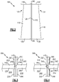
Figure 5A schematically illustrates a view of the relief void of a split case, such as the split case illustrated inFigure 2 , according to an embodiment. -
Figure 5B schematically illustrates an axially aligned view of the relief void ofFigure 5A , according to an embodiment. -
Figure 5C schematically illustrates a cross sectional view of the relief void ofFigure 5B along view line C, according to an embodiment. -
Figure 1 schematically illustrates agas turbine engine 20. Thegas turbine engine 20 is disclosed herein as a two-spool turbofan that generally incorporates afan section 22, acompressor section 24, acombustor section 26 and aturbine section 28. Alternative engines might include an augmentor section (not shown) among other systems or features. Thefan section 22 drives air along a bypass flow path B in a bypass duct defined within anacelle 15, while thecompressor section 24 drives air along a core flow path C for compression and communication into thecombustor section 26 then expansion through theturbine section 28. Although depicted as a two-spool turbofan gas turbine engine in the disclosed non-limiting embodiment, it should be understood that the concepts described herein are not limited to use with two-spool turbofans as the teachings may be applied to other types of turbine engines including three-spool architectures. - The
exemplary engine 20 generally includes alow speed spool 30 and ahigh speed spool 32 mounted for rotation about an engine central longitudinal axis A relative to an enginestatic structure 36 viaseveral bearing systems 38. It should be understood thatvarious bearing systems 38 at various locations may alternatively or additionally be provided, and the location ofbearing systems 38 may be varied as appropriate to the application. - The
low speed spool 30 generally includes aninner shaft 40 that interconnects afan 42, a first (or low)pressure compressor 44 and a first (or low)pressure turbine 46. Theinner shaft 40 is connected to thefan 42 through a speed change mechanism, which in exemplarygas turbine engine 20 is illustrated as a gearedarchitecture 48 to drive thefan 42 at a lower speed than thelow speed spool 30. Thehigh speed spool 32 includes anouter shaft 50 that interconnects a second (or high)pressure compressor 52 and a second (or high)pressure turbine 54. Acombustor 56 is arranged inexemplary gas turbine 20 between thehigh pressure compressor 52 and thehigh pressure turbine 54. Amid-turbine frame 57 of the enginestatic structure 36 is arranged generally between thehigh pressure turbine 54 and thelow pressure turbine 46. Themid-turbine frame 57 further supports bearingsystems 38 in theturbine section 28. Theinner shaft 40 and theouter shaft 50 are concentric and rotate viabearing systems 38 about the engine central longitudinal axis A which is collinear with their longitudinal axes. - The core airflow is compressed by the
low pressure compressor 44 then thehigh pressure compressor 52, mixed and burned with fuel in thecombustor 56, then expanded over thehigh pressure turbine 54 andlow pressure turbine 46. Themid-turbine frame 57 includesairfoils 59 which are in the core airflow path C. Theturbines low speed spool 30 andhigh speed spool 32 in response to the expansion. It will be appreciated that each of the positions of thefan section 22,compressor section 24,combustor section 26,turbine section 28, and fandrive gear system 48 may be varied. For example,gear system 48 may be located aft ofcombustor section 26 or even aft ofturbine section 28, andfan section 22 may be positioned forward or aft of the location ofgear system 48. - The
engine 20 in one example is a high-bypass geared aircraft engine. In a further example, theengine 20 bypass ratio is greater than about six, with an example embodiment being greater than about ten, the gearedarchitecture 48 is an epicyclic gear train, such as a planetary gear system or other gear system, with a gear reduction ratio of greater than about 2.3 and thelow pressure turbine 46 has a pressure ratio that is greater than about five. In one disclosed embodiment, theengine 20 bypass ratio is greater than about ten, the fan diameter is significantly larger than that of thelow pressure compressor 44, and thelow pressure turbine 46 has a pressure ratio that is greater than about five.Low pressure turbine 46 pressure ratio is pressure measured prior to inlet oflow pressure turbine 46 as related to the pressure at the outlet of thelow pressure turbine 46 prior to an exhaust nozzle. The gearedarchitecture 48 may be an epicycle gear train, such as a planetary gear system or other gear system, with a gear reduction ratio of greater than about 2.3:1. It should be understood, however, that the above parameters are only exemplary of one embodiment of a geared architecture engine and that the present invention is applicable to other gas turbine engines including direct drive turbofans. - A significant amount of thrust is provided by the bypass flow B due to the high bypass ratio. The
fan section 22 of theengine 20 is designed for a particular flight condition -- typically cruise at about 0.8 Mach and about 35,000 feet (10,668 m). The flight condition of 0.8 Mach and 35,000 ft (10,668 m), with the engine at its best fuel consumption - also known as "bucket cruise Thrust Specific Fuel Consumption ('TSFC')" - is the industry standard parameter of lbm of fuel being burned divided by lbf of thrust the engine produces at that minimum point. "Low fan pressure ratio" is the pressure ratio across the fan blade alone, without a Fan Exit Guide Vane ("FEGV") system. The low fan pressure ratio as disclosed herein according to one non-limiting embodiment is less than about 1.45. "Low corrected fan tip speed" is the actual fan tip speed in ft/sec divided by an industry standard temperature correction of [(Tram °R) / (518.7 °R)]0.5 (where °R = K x 9/5). The "Low corrected fan tip speed" as disclosed herein according to one non-limiting embodiment is less than about 1150 ft / second (350.5 m/s). -
Figure 2 schematically illustrates a side view of asplit case 100 for one of thecompressor section 24 or theturbine section 28 of thegas turbine engine 20 illustrated inFigure 1 , according to an embodiment. Thesplit case 100 includes twosections body portion 110, and two axially alignedsplit flanges 120. While only asingle split flange 120 of eachsection Figure 2 , it is understood that thesecond split flange 120 is located 180 degrees offset from thefirst split flange 120, and is hidden in the illustrated view. Each axially alignedsplit flange 120 is connected to acorresponding split flange 120 of theother section split case 100 is acircumferential flange 130. In an assembled gas turbine engine, such as thegas turbine engine 20 ofFigure 1 , each of thecircumferential flanges 130 is connected to an adjacent structural component, such as a fan case or an adjacent turbine engine splitcase 100. - Each of the
circumferential flanges 130 includes arelief void 140 positioned at thesplit flanges 120. Therelief Void 140 accommodates thermal growth and separation of thesplit flanges 120 that occurs during operation of thegas turbine engine 20, thereby reducing stresses imparted on an adjacent component by thermal growth of thesplit case 100. - During operation of the
gas turbine engine 20, thesplit case 100 undergoes heating and cooling, which results in thermal expansion and contraction along thesplit flange 120. The split flanges 120 are mechanically connected toadjacent split flanges 120, and therefore the split flanges are prevented from completely separating due to the thermal growth. The split flanges 120 are not mechanically connected at the axial ends of each split flange 120 (at the circumferential flanges 130). As a result, the thermal expansion within thesplit flanges 120 causes a separation at thecircumferential flanges 130, and forces a portion of thecircumferential flange 130 to protrude axially away from thesplit case 100. - Incorporation of the
relief void 140 in thecircumferential flanges 130, prevents the axially protruding portion of thecircumferential flanges 130 from contacting an adjacent component connected to thecircumferential flange 130 and causing stress on the adjacent component. - With continued reference to
Figure 1 ,Figure 4 illustrates the thermal growth of a joint 300 between asplit case 310 and aconnected case 312. As with the examples ofFigures 2 and 3 , thesplit case 310 includes splitflanges 320 that are connected to each other via any known flange connection arrangement. The split flanges 320 join thecircumferential flange 330, and there is no flange connection between thesplit flanges 320 at thecircumferential flange 330. - The illustrated embodiment of
Figure 4 includes anadjacent split case 312 connected to thesplit case 310 via a connection betweencircumferential flanges split case 310 can be connected to any adjacent turbine engine structure including alternate case configurations, an end wall, or any other turbine engine structure and the connection is not limited to a connection between split cases. - During operation of the
gas turbine engine 20, thesplit case 310 heats up, causing thermal growth in thesplit case 310 as described above. The pulling apart of thesplit flange 320 is illustrated by agap 342 between thesplit flanges 320. The pulling apart at thegap 342 causes an edge 344, or corner, thecircumferential flange 330 to protrude axially away from thesplit case 310. The axial protrusion extends into thecircumferential flange 350 of theadjacent case 312 causing deformation or stress at the contact point. A dashedline 346 indicates the position of the edge 344 of thecircumferential flange 330 when thesplit case 310 is not undergoing thermal growth. In the illustrated example ofFigure 4 , the protrusion of the edge 344 and thegap 342 between thesplit flanges 320 is exaggerated for illustrative effect. - With continued reference to
Figures 1 and2 , and with like numerals indicating like elements,Figure 3 illustrates aconnection 200 between asplit case 210 and anadjacent case 212, according to an embodiment. In alternate examples, thesplit case 210 can be connected to any adjacent turbine engine structure including alternate case configurations, an end wall, or any other turbine engine structure. Thesplit case 210 includes splitflanges 220 aligned axially with an axis defined by thesplit case 210. The split flanges 220 join with acircumferential flange 230 to form a unitary flange structure. Positioned in thecircumferential flange 230, at the joint between thesplit flanges 220 and thecircumferential flange 230, is arelief void 240. Therelief void 240 is a portion of thecircumferential flange 230 that is removed (i.e. a void) to allow for thermal growth of thesplit case 210 without stressing anadjacent case 212. In some examples, therelief void 240 is a groove. - The
circumferential flange 230 of thesplit case 210 is connected to acircumferential flange 250 of theadjacent case 212 via any known flange connection means. In one example thesplit case 210 and theadjacent case 212 are connected via bolts, or other fasteners, that protrude through the correspondingcircumferential flanges adjacent case 212 is a split case having axially alignedsplit flanges 260. In alternate embodiments, alternate case styles incorporating acircumferential flange 250 can be used as the adjacent case to the same effect. In yet further embodiments, thecircumferential flange 230 of thesplit case 210 can be connected to any adjacent engine structure, and is not limited to connecting to aflange 250 of anadjacent split case 212. - In the illustrated examples, a
third layer 270 is used according to known principles to enhance the connection between thecircumferential flanges third layer 270 may be omitted, or additional layers may be included. - With continued reference to
Figures 1-3 , and with like numerals indicating like elements, - Referring again to
Figure 3 , arelief void 240 is included in thecircumferential flange 230 at thesplit flange 220 in order to prevent the protrusion of anedge 244 into an adjacent component. When the illustratedsplit case 210 ofFigure 3 undergoes thermal growth, a gap opens at a joint between thesplit flanges 220 at anedge 244 illustrated in the example ofFigure 4 . The presence of therelief void 240 sets theedge 244 axially away from contact with the adjacentcircumferential flange 250 and thethird layer 270. As a result, when thesplit case 210 undergoes thermal growth and theedge 244 protrudes axially away from thesplit case 210, theedge 244 is prevented from deforming or stressing the adjacentcircumferential flange 250 orthird layer 270, and stress resulting from the thermal growth is thereby minimized. - With continued reference to
Figures 1-4 , and with like numerals indicating like elements,Figures 5A-5C illustrate arelief void portion 440 of asplit case 400 in greater detail. -
Figure 5A provides a radially inward looking external view of the joint between asplit flange 420 and thecircumferential flange 430 at arelief void 440. Therelief void 440 is defined by a groove on an external surface of thecircumferential flange 430 at thesplit flanges 420. The groove is radially aligned and extends inward from a radiallyoutward edge 441 of thecircumferential flange 430. The groove extends a partial radial length of the circumferential flange from a radially outward edge of the circumferential flange. The groove includes an axiallyinward edge 442. The axiallyinward edge 442 includes a curvature designed to allow the axiallyinward edge 442 to flex during thermal growth without causing elastic deformation of theedge 442. - The groove further includes an axially
outer edge 444. The illustrated axiallyouter edge 444 includes a small curvature to allow a gap to form without forcing the axiallyouter edge 444 to protrude into an adjacent structure. In alternate examples, the axiallyouter edge 444 can be a chamfered edge instead of a curve and achieve a similar function. -
Figure 5B illustrates an axially aligned view of thecircumferential flange 430 ofFigure 5A . The view ofFigure 5B shows an axially alignededge 446 of the groove defining therelief void 440. The axially alignededge 446 is curved similar to the axiallyinward edge 442, and achieves the same function. The groove defined by therelief void 440 extends only partially into thecircumferential flange 430 along the axis defined by the split flange case, thereby defining aback portion 447 of the groove. - In an alternate example, the axially aligned
edge 446 can be chamfered instead of curved. -
Figure 5C illustrates a cross sectional view of thecircumferential flange 430 and thesplit flange 420 ofFigure 5B along view line C. Thesplit flange 420 connects to thecircumferential flange 430 as illustrated inFigures 2-4 . The groove defining therelief void 440 includes asolid backing wall 447 that prevents the groove from breaking the circumferential flange. The radiallyinward edge 442 of the circumferential flange in the illustrated example connects the curve axially alignededge 446 to the axiallyouter edge 444. In alternate examples. The radiallyinward edge 442 can be a chamfered void instead of the curved void illustrated and achieve the same effect. - While the above described split
case bodies 110 of the case sections (seeFigure 2 ) could include additional features not illustrated in order to accommodate the contained gas turbine engine components, and still fall within the above disclosure. - It is further understood that any of the above described concepts can be used alone or in combination with any or all of the other above described concepts. Although an embodiment of this invention has been disclosed, a worker of ordinary skill in this art would recognize that certain modifications would come within the scope of this invention. For that reason, the following claims should be studied to determine the true scope and content of this invention.
Claims (10)
- A split case (100; 210; 310) for a gas turbine engine comprising:a plurality of split case portions (102, 104) defining a turbine engine case section;each of said split case portions (102, 104) in said plurality of split case portions (102, 104) including a first split flange (120; 220; 250; 320; 420) and a second split flange (120; 220; 250; 320; 420), wherein each of said first split flange (120; 220; 250; 320; 420) and said second split flange (120; 220; 250; 320; 420) are axially aligned;each of said first split flange (120; 220; 250; 320; 420) and said second split flange (120; 220; 250; 320; 420) is configured to mechanically connect to another split case portion (102, 104) in said plurality of split case portions (102, 104) defining said turbine engine case section; each of said split case portions (102, 104) in said plurality of split case portions (102, 104) including a circumferential flange portion (130; 230; 330; 430) located at an axial end, wherein the circumferential flange portion (130; 230; 330; 430) is configured to connect the turbine engine case section to an adjacent turbine engine component;each of said circumferential flanges (130; 230; 330; 430) including a thermal expansion relief void (140; 240; 340; 440) positioned at said split flanges (120; 220; 250; 320; 420); andthe thermal expansion relief void (140; 240; 340; 440) is configured to allow for thermal growth of the split case (100; 210; 310) without stressing an adjacent case (212; 312);characterised in that:each of said relief voids (140; 240; 340; 440) extends partially into said circumferential flange (130; 230; 330; 430), such that a radially aligned groove in said circumferential flange (130; 230; 330; 430) is defined;said radially aligned groove extends a partial radial length of the circumferential flange (130; 230; 330; 430) from a radially outward edge of the circumferential flange (130; 230; 330; 430) thereby defining a radially inward wall of the relief void (140; 240; 340; 440);said radially inward wall of the relief void (140; 240; 340; 440) comprises an axially inward edge (442) connected to a back portion (447) of the circumferential flange (130; 230; 330; 430), and an axially outward edge (444) connected to an axial end of the circumferential flange (130; 230; 330; 430); andthe radially aligned groove extends only partially into the circumferential flange (130; 230; 330; 430) along an axis defined by the split case (100; 210; 310), thereby defining the back portion (447).
- The split case (100; 210; 310) of claim 1, wherein said axially inward edge (442) comprises a curvature.
- The split case (100; 210; 310) of claim 1, wherein said axially inward edge (442) comprises a chamfer.
- The split case (100; 210; 310) of claim 1, 2 or 3, wherein said axially outward edge (444) comprises a curvature.
- The split case (100; 210; 310) of claim 1, 2 or 3, wherein said axially outward edge (444) comprises a chamfer.
- A gas turbine engine (20) comprising:
a split case structure (100; 210; 310) configured to circumferentially surround at least a portion of said gas turbine engine (20), the split case structure (100; 210; 310) comprising a split case (100; 210; 310) of any preceding claim, wherein the plurality of split case portions (102, 104) define the split case structure (100; 210; 310). - The gas turbine engine (20) of claim 6, further comprising at least the adjacent case structure (212; 312), wherein said split case structure (100; 210; 310) is mechanically connected to said adjacent case structure (212; 312) via said circumferential flanges (130; 230; 330; 430).
- The gas turbine engine (20) of claim 7, further comprising a material layer connecting said circumferential flanges (130; 230; 330; 430) to a circumferential flange (250; 350; 430) of said adjacent case structure (212; 312).
- The gas turbine engine (20) of claim 7 or 8, wherein each of said relief voids (140; 240; 340; 440) is configured to reduce deflection in said adjacent case structure (212; 312) due to thermal expansion of said split case structure (100; 210; 310).
- A method of reducing deflection in an adjacent turbine engine case component caused by thermal growth of a split case (100; 210; 310) comprising:disposing at least one relief void (140; 240; 340; 440) in a circumferential flange (130; 230; 330; 430) of the split case (100; 210; 310), said at least one relief void (140; 240; 340; 440) positioned circumferentially at a split flange joint of said circumferential flange (130; 230; 330; 430),wherein the at least one relief void (140; 240; 340; 440) is configured to allow for thermal growth of the split case (100; 210; 310) without stressing the adjacent turbine engine case component (212; 312);characterised in that:
disposing at least one relief void (140; 240; 340; 440) in said circumferential flange (130; 230; 330; 430) of the split case (100; 210; 310) comprises disposing a radially aligned groove in said circumferential flange (130; 230; 330; 430), the radially aligned groove extending a partial radial length of the circumferential flange (130; 230; 330; 430) from a radially outward edge of the circumferential flange (130; 230; 330; 430), thereby defining a radially inward wall of the relief void (140; 240; 340; 440), and said radially inward wall of the relief void (140; 240; 340; 440) is defined by an axially inward edge (442) connected a back portion (447) of the circumferential flange (130; 230; 330; 430) and an axially outward edge (444) connected to an axial end of the split case portion (102, 104), wherein the radially aligned groove extends only partially into the circumferential flange (130; 230; 330; 430) along an axis defined by the split case (100; 210; 310), thereby defining the back portion (447).
Applications Claiming Priority (2)
| Application Number | Priority Date | Filing Date | Title |
|---|---|---|---|
| US201361904158P | 2013-11-14 | 2013-11-14 | |
| PCT/US2014/064261 WO2015116277A2 (en) | 2013-11-14 | 2014-11-06 | Flange relief for split casing |
Publications (3)
| Publication Number | Publication Date |
|---|---|
| EP3068981A2 EP3068981A2 (en) | 2016-09-21 |
| EP3068981A4 EP3068981A4 (en) | 2017-01-18 |
| EP3068981B1 true EP3068981B1 (en) | 2022-08-17 |
Family
ID=53757895
Family Applications (1)
| Application Number | Title | Priority Date | Filing Date |
|---|---|---|---|
| EP14881097.1A Active EP3068981B1 (en) | 2013-11-14 | 2014-11-06 | Flange relief for split casing |
Country Status (3)
| Country | Link |
|---|---|
| US (1) | US10202870B2 (en) |
| EP (1) | EP3068981B1 (en) |
| WO (1) | WO2015116277A2 (en) |
Families Citing this family (4)
| Publication number | Priority date | Publication date | Assignee | Title |
|---|---|---|---|---|
| US11428124B2 (en) | 2018-11-21 | 2022-08-30 | Raytheon Technologies Corporation | Flange stress-reduction features |
| US11421555B2 (en) | 2018-12-07 | 2022-08-23 | Raytheon Technologies Corporation | Case flange with scallop features |
| US11092038B2 (en) * | 2019-03-26 | 2021-08-17 | Raytheon Technologies Corporation | Notched axial flange for a split case compressor |
| EP3715590A1 (en) * | 2019-03-27 | 2020-09-30 | Siemens Aktiengesellschaft | Turbomachinery housing assembly |
Family Cites Families (19)
| Publication number | Priority date | Publication date | Assignee | Title |
|---|---|---|---|---|
| CH499012A (en) * | 1968-12-03 | 1970-11-15 | Siemens Ag | Arrangement for the axially fixed and radially movable mounting of turbine housing parts |
| US4502809A (en) * | 1981-08-31 | 1985-03-05 | Carrier Corporation | Method and apparatus for controlling thermal growth |
| US4599147A (en) | 1984-07-11 | 1986-07-08 | Federal-Mogul Corporation | Method for making improved split bearings having masked relief areas |
| FR2607198B1 (en) | 1986-11-26 | 1990-05-04 | Snecma | COMPRESSOR HOUSING SUITABLE FOR ACTIVE PILOTAGE OF ITS EXPANSIONS AND MANUFACTURING METHOD THEREOF |
| US5354174A (en) | 1990-09-12 | 1994-10-11 | United Technologies Corporation | Backbone support structure for compressor |
| US5224824A (en) | 1990-09-12 | 1993-07-06 | United Technologies Corporation | Compressor case construction |
| US5131811A (en) | 1990-09-12 | 1992-07-21 | United Technologies Corporation | Fastener mounting for multi-stage compressor |
| US5503490A (en) * | 1994-05-13 | 1996-04-02 | United Technologies Corporation | Thermal load relief ring for engine case |
| US5593276A (en) * | 1995-06-06 | 1997-01-14 | General Electric Company | Turbine shroud hanger |
| US5605438A (en) * | 1995-12-29 | 1997-02-25 | General Electric Co. | Casing distortion control for rotating machinery |
| US6352404B1 (en) * | 2000-02-18 | 2002-03-05 | General Electric Company | Thermal control passages for horizontal split-line flanges of gas turbine engine casings |
| US6681577B2 (en) | 2002-01-16 | 2004-01-27 | General Electric Company | Method and apparatus for relieving stress in a combustion case in a gas turbine engine |
| US6896491B2 (en) | 2002-12-09 | 2005-05-24 | Caterpillar Inc | Bearing mounting flange having flexibility pocket |
| US7094029B2 (en) * | 2003-05-06 | 2006-08-22 | General Electric Company | Methods and apparatus for controlling gas turbine engine rotor tip clearances |
| US7121095B2 (en) * | 2003-08-11 | 2006-10-17 | General Electric Company | Combustor dome assembly of a gas turbine engine having improved deflector plates |
| US6941633B2 (en) * | 2003-08-28 | 2005-09-13 | United Technologies Corporation | Tooling provision for split cases |
| US20060263208A1 (en) | 2005-01-25 | 2006-11-23 | Stone Stephen S | Split case seals and methods |
| US8210802B2 (en) * | 2008-01-22 | 2012-07-03 | General Electric Company | Turbine casing |
| US8662819B2 (en) | 2008-12-12 | 2014-03-04 | United Technologies Corporation | Apparatus and method for preventing cracking of turbine engine cases |
-
2014
- 2014-11-06 EP EP14881097.1A patent/EP3068981B1/en active Active
- 2014-11-06 WO PCT/US2014/064261 patent/WO2015116277A2/en active Application Filing
- 2014-11-06 US US15/034,344 patent/US10202870B2/en active Active
Also Published As
| Publication number | Publication date |
|---|---|
| US20160281541A1 (en) | 2016-09-29 |
| WO2015116277A3 (en) | 2015-10-29 |
| WO2015116277A2 (en) | 2015-08-06 |
| US10202870B2 (en) | 2019-02-12 |
| EP3068981A4 (en) | 2017-01-18 |
| EP3068981A2 (en) | 2016-09-21 |
Similar Documents
| Publication | Publication Date | Title |
|---|---|---|
| EP3080419B1 (en) | Wrapped dog bone seal | |
| EP2975226B1 (en) | Turbine section support for a gas turbine engine | |
| EP3798427B1 (en) | Turbomachine geared architecture support assembly | |
| EP3034807B1 (en) | Gas turbine engine mid-turbine frame tie rod arrangement | |
| US10655499B2 (en) | Flexible preloaded ball bearing assembly | |
| EP3428408B1 (en) | Gas turbine engine variable vane end wall insert | |
| EP3068981B1 (en) | Flange relief for split casing | |
| EP3708791B1 (en) | Integrated fan inlet case and bearing support for a gas turbine engine | |
| EP2985419B1 (en) | Turbomachine blade assembly with blade root seals | |
| EP2930303B1 (en) | Gas turbine engine coupling stack | |
| EP3608514B1 (en) | Structural support for blade outer air seal assembly | |
| US11008879B2 (en) | Continuous wedge vane arm with failsafe retention clip | |
| EP3543469B1 (en) | Blade outer air seal assembly with feather seal | |
| EP3401515B1 (en) | Turbine vane with inner circumferential anti-rotation features | |
| EP2905427B1 (en) | Gas turbine engine sealing arrangement | |
| EP2971578B1 (en) | Method of assembling a gas turbine engine front architecture and corresponding gas turbine engine front architecture | |
| EP2900978B1 (en) | Compressor section comprising a seal hook mount structure with overlapped coating | |
| EP3101236B1 (en) | Trailing edge platform seals | |
| EP3760843B1 (en) | Duct assembly for a gas turbine engine | |
| EP3597870B1 (en) | Gas turbine engine | |
| EP3708773A2 (en) | Seal for a rotor stack, corresponding gas turbine engine and method of sealing a shaft relatively to a rotor disk | |
| EP3786417A1 (en) | Axial retention geometry for a turbine engine blade outer air seal | |
| US20210071544A1 (en) | Geometry for a turbine engine blade outer air seal |
Legal Events
| Date | Code | Title | Description |
|---|---|---|---|
| PUAI | Public reference made under article 153(3) epc to a published international application that has entered the european phase |
Free format text: ORIGINAL CODE: 0009012 |
|
| 17P | Request for examination filed |
Effective date: 20160614 |
|
| AK | Designated contracting states |
Kind code of ref document: A2 Designated state(s): AL AT BE BG CH CY CZ DE DK EE ES FI FR GB GR HR HU IE IS IT LI LT LU LV MC MK MT NL NO PL PT RO RS SE SI SK SM TR |
|
| AX | Request for extension of the european patent |
Extension state: BA ME |
|
| RAP1 | Party data changed (applicant data changed or rights of an application transferred) |
Owner name: UNITED TECHNOLOGIES CORPORATION |
|
| A4 | Supplementary search report drawn up and despatched |
Effective date: 20161219 |
|
| RIC1 | Information provided on ipc code assigned before grant |
Ipc: F02C 7/20 20060101ALI20161213BHEP Ipc: F01D 25/28 20060101ALI20161213BHEP Ipc: F01D 25/26 20060101AFI20161213BHEP Ipc: F01D 25/24 20060101ALI20161213BHEP |
|
| DAX | Request for extension of the european patent (deleted) | ||
| STAA | Information on the status of an ep patent application or granted ep patent |
Free format text: STATUS: EXAMINATION IS IN PROGRESS |
|
| 17Q | First examination report despatched |
Effective date: 20200702 |
|
| STAA | Information on the status of an ep patent application or granted ep patent |
Free format text: STATUS: EXAMINATION IS IN PROGRESS |
|
| RAP1 | Party data changed (applicant data changed or rights of an application transferred) |
Owner name: RAYTHEON TECHNOLOGIES CORPORATION |
|
| STAA | Information on the status of an ep patent application or granted ep patent |
Free format text: STATUS: EXAMINATION IS IN PROGRESS |
|
| GRAP | Despatch of communication of intention to grant a patent |
Free format text: ORIGINAL CODE: EPIDOSNIGR1 |
|
| STAA | Information on the status of an ep patent application or granted ep patent |
Free format text: STATUS: GRANT OF PATENT IS INTENDED |
|
| INTG | Intention to grant announced |
Effective date: 20220324 |
|
| GRAS | Grant fee paid |
Free format text: ORIGINAL CODE: EPIDOSNIGR3 |
|
| GRAA | (expected) grant |
Free format text: ORIGINAL CODE: 0009210 |
|
| STAA | Information on the status of an ep patent application or granted ep patent |
Free format text: STATUS: THE PATENT HAS BEEN GRANTED |
|
| AK | Designated contracting states |
Kind code of ref document: B1 Designated state(s): AL AT BE BG CH CY CZ DE DK EE ES FI FR GB GR HR HU IE IS IT LI LT LU LV MC MK MT NL NO PL PT RO RS SE SI SK SM TR |
|
| REG | Reference to a national code |
Ref country code: CH Ref legal event code: EP |
|
| REG | Reference to a national code |
Ref country code: DE Ref legal event code: R096 Ref document number: 602014084673 Country of ref document: DE |
|
| REG | Reference to a national code |
Ref country code: IE Ref legal event code: FG4D |
|
| REG | Reference to a national code |
Ref country code: AT Ref legal event code: REF Ref document number: 1512320 Country of ref document: AT Kind code of ref document: T Effective date: 20220915 |
|
| REG | Reference to a national code |
Ref country code: NL Ref legal event code: MP Effective date: 20220817 |
|
| REG | Reference to a national code |
Ref country code: LT Ref legal event code: MG9D |
|
| PG25 | Lapsed in a contracting state [announced via postgrant information from national office to epo] |
Ref country code: SE Free format text: LAPSE BECAUSE OF FAILURE TO SUBMIT A TRANSLATION OF THE DESCRIPTION OR TO PAY THE FEE WITHIN THE PRESCRIBED TIME-LIMIT Effective date: 20220817 Ref country code: RS Free format text: LAPSE BECAUSE OF FAILURE TO SUBMIT A TRANSLATION OF THE DESCRIPTION OR TO PAY THE FEE WITHIN THE PRESCRIBED TIME-LIMIT Effective date: 20220817 Ref country code: PT Free format text: LAPSE BECAUSE OF FAILURE TO SUBMIT A TRANSLATION OF THE DESCRIPTION OR TO PAY THE FEE WITHIN THE PRESCRIBED TIME-LIMIT Effective date: 20221219 Ref country code: NO Free format text: LAPSE BECAUSE OF FAILURE TO SUBMIT A TRANSLATION OF THE DESCRIPTION OR TO PAY THE FEE WITHIN THE PRESCRIBED TIME-LIMIT Effective date: 20221117 Ref country code: NL Free format text: LAPSE BECAUSE OF FAILURE TO SUBMIT A TRANSLATION OF THE DESCRIPTION OR TO PAY THE FEE WITHIN THE PRESCRIBED TIME-LIMIT Effective date: 20220817 Ref country code: LV Free format text: LAPSE BECAUSE OF FAILURE TO SUBMIT A TRANSLATION OF THE DESCRIPTION OR TO PAY THE FEE WITHIN THE PRESCRIBED TIME-LIMIT Effective date: 20220817 Ref country code: LT Free format text: LAPSE BECAUSE OF FAILURE TO SUBMIT A TRANSLATION OF THE DESCRIPTION OR TO PAY THE FEE WITHIN THE PRESCRIBED TIME-LIMIT Effective date: 20220817 Ref country code: FI Free format text: LAPSE BECAUSE OF FAILURE TO SUBMIT A TRANSLATION OF THE DESCRIPTION OR TO PAY THE FEE WITHIN THE PRESCRIBED TIME-LIMIT Effective date: 20220817 Ref country code: ES Free format text: LAPSE BECAUSE OF FAILURE TO SUBMIT A TRANSLATION OF THE DESCRIPTION OR TO PAY THE FEE WITHIN THE PRESCRIBED TIME-LIMIT Effective date: 20220817 |
|
| REG | Reference to a national code |
Ref country code: AT Ref legal event code: MK05 Ref document number: 1512320 Country of ref document: AT Kind code of ref document: T Effective date: 20220817 |
|
| PG25 | Lapsed in a contracting state [announced via postgrant information from national office to epo] |
Ref country code: PL Free format text: LAPSE BECAUSE OF FAILURE TO SUBMIT A TRANSLATION OF THE DESCRIPTION OR TO PAY THE FEE WITHIN THE PRESCRIBED TIME-LIMIT Effective date: 20220817 Ref country code: IS Free format text: LAPSE BECAUSE OF FAILURE TO SUBMIT A TRANSLATION OF THE DESCRIPTION OR TO PAY THE FEE WITHIN THE PRESCRIBED TIME-LIMIT Effective date: 20221217 Ref country code: HR Free format text: LAPSE BECAUSE OF FAILURE TO SUBMIT A TRANSLATION OF THE DESCRIPTION OR TO PAY THE FEE WITHIN THE PRESCRIBED TIME-LIMIT Effective date: 20220817 Ref country code: GR Free format text: LAPSE BECAUSE OF FAILURE TO SUBMIT A TRANSLATION OF THE DESCRIPTION OR TO PAY THE FEE WITHIN THE PRESCRIBED TIME-LIMIT Effective date: 20221118 |
|
| PG25 | Lapsed in a contracting state [announced via postgrant information from national office to epo] |
Ref country code: SM Free format text: LAPSE BECAUSE OF FAILURE TO SUBMIT A TRANSLATION OF THE DESCRIPTION OR TO PAY THE FEE WITHIN THE PRESCRIBED TIME-LIMIT Effective date: 20220817 Ref country code: RO Free format text: LAPSE BECAUSE OF FAILURE TO SUBMIT A TRANSLATION OF THE DESCRIPTION OR TO PAY THE FEE WITHIN THE PRESCRIBED TIME-LIMIT Effective date: 20220817 Ref country code: DK Free format text: LAPSE BECAUSE OF FAILURE TO SUBMIT A TRANSLATION OF THE DESCRIPTION OR TO PAY THE FEE WITHIN THE PRESCRIBED TIME-LIMIT Effective date: 20220817 Ref country code: CZ Free format text: LAPSE BECAUSE OF FAILURE TO SUBMIT A TRANSLATION OF THE DESCRIPTION OR TO PAY THE FEE WITHIN THE PRESCRIBED TIME-LIMIT Effective date: 20220817 Ref country code: AT Free format text: LAPSE BECAUSE OF FAILURE TO SUBMIT A TRANSLATION OF THE DESCRIPTION OR TO PAY THE FEE WITHIN THE PRESCRIBED TIME-LIMIT Effective date: 20220817 |
|
| REG | Reference to a national code |
Ref country code: DE Ref legal event code: R097 Ref document number: 602014084673 Country of ref document: DE |
|
| PG25 | Lapsed in a contracting state [announced via postgrant information from national office to epo] |
Ref country code: SK Free format text: LAPSE BECAUSE OF FAILURE TO SUBMIT A TRANSLATION OF THE DESCRIPTION OR TO PAY THE FEE WITHIN THE PRESCRIBED TIME-LIMIT Effective date: 20220817 Ref country code: EE Free format text: LAPSE BECAUSE OF FAILURE TO SUBMIT A TRANSLATION OF THE DESCRIPTION OR TO PAY THE FEE WITHIN THE PRESCRIBED TIME-LIMIT Effective date: 20220817 |
|
| PLBE | No opposition filed within time limit |
Free format text: ORIGINAL CODE: 0009261 |
|
| STAA | Information on the status of an ep patent application or granted ep patent |
Free format text: STATUS: NO OPPOSITION FILED WITHIN TIME LIMIT |
|
| P01 | Opt-out of the competence of the unified patent court (upc) registered |
Effective date: 20230520 |
|
| PG25 | Lapsed in a contracting state [announced via postgrant information from national office to epo] |
Ref country code: MC Free format text: LAPSE BECAUSE OF FAILURE TO SUBMIT A TRANSLATION OF THE DESCRIPTION OR TO PAY THE FEE WITHIN THE PRESCRIBED TIME-LIMIT Effective date: 20220817 Ref country code: AL Free format text: LAPSE BECAUSE OF FAILURE TO SUBMIT A TRANSLATION OF THE DESCRIPTION OR TO PAY THE FEE WITHIN THE PRESCRIBED TIME-LIMIT Effective date: 20220817 |
|
| REG | Reference to a national code |
Ref country code: CH Ref legal event code: PL |
|
| 26N | No opposition filed |
Effective date: 20230519 |
|
| REG | Reference to a national code |
Ref country code: BE Ref legal event code: MM Effective date: 20221130 |
|
| PG25 | Lapsed in a contracting state [announced via postgrant information from national office to epo] |
Ref country code: LI Free format text: LAPSE BECAUSE OF NON-PAYMENT OF DUE FEES Effective date: 20221130 Ref country code: CH Free format text: LAPSE BECAUSE OF NON-PAYMENT OF DUE FEES Effective date: 20221130 |
|
| PG25 | Lapsed in a contracting state [announced via postgrant information from national office to epo] |
Ref country code: SI Free format text: LAPSE BECAUSE OF FAILURE TO SUBMIT A TRANSLATION OF THE DESCRIPTION OR TO PAY THE FEE WITHIN THE PRESCRIBED TIME-LIMIT Effective date: 20220817 Ref country code: LU Free format text: LAPSE BECAUSE OF NON-PAYMENT OF DUE FEES Effective date: 20221106 |
|
| PG25 | Lapsed in a contracting state [announced via postgrant information from national office to epo] |
Ref country code: IE Free format text: LAPSE BECAUSE OF NON-PAYMENT OF DUE FEES Effective date: 20221106 |
|
| PG25 | Lapsed in a contracting state [announced via postgrant information from national office to epo] |
Ref country code: BE Free format text: LAPSE BECAUSE OF NON-PAYMENT OF DUE FEES Effective date: 20221130 |
|
| PGFP | Annual fee paid to national office [announced via postgrant information from national office to epo] |
Ref country code: GB Payment date: 20231019 Year of fee payment: 10 |
|
| PGFP | Annual fee paid to national office [announced via postgrant information from national office to epo] |
Ref country code: FR Payment date: 20231019 Year of fee payment: 10 Ref country code: DE Payment date: 20231019 Year of fee payment: 10 |
|
| PG25 | Lapsed in a contracting state [announced via postgrant information from national office to epo] |
Ref country code: HU Free format text: LAPSE BECAUSE OF FAILURE TO SUBMIT A TRANSLATION OF THE DESCRIPTION OR TO PAY THE FEE WITHIN THE PRESCRIBED TIME-LIMIT; INVALID AB INITIO Effective date: 20141106 |