EP3300615B1 - Hand-held cigarette-making machine - Google Patents
Hand-held cigarette-making machine Download PDFInfo
- Publication number
- EP3300615B1 EP3300615B1 EP17190642.3A EP17190642A EP3300615B1 EP 3300615 B1 EP3300615 B1 EP 3300615B1 EP 17190642 A EP17190642 A EP 17190642A EP 3300615 B1 EP3300615 B1 EP 3300615B1
- Authority
- EP
- European Patent Office
- Prior art keywords
- tobacco
- sliding member
- cigarette tube
- cigarette
- empty
- Prior art date
- Legal status (The legal status is an assumption and is not a legal conclusion. Google has not performed a legal analysis and makes no representation as to the accuracy of the status listed.)
- Active
Links
Images


Classifications
-
- A—HUMAN NECESSITIES
- A24—TOBACCO; CIGARS; CIGARETTES; SIMULATED SMOKING DEVICES; SMOKERS' REQUISITES
- A24C—MACHINES FOR MAKING CIGARS OR CIGARETTES
- A24C5/00—Making cigarettes; Making tipping materials for, or attaching filters or mouthpieces to, cigars or cigarettes
- A24C5/40—Hand-driven apparatus for making cigarettes
- A24C5/42—Pocket cigarette-fillers
- A24C5/425—Pocket cigarette-fillers for obtaining cigarettes of various lengths
-
- A—HUMAN NECESSITIES
- A24—TOBACCO; CIGARS; CIGARETTES; SIMULATED SMOKING DEVICES; SMOKERS' REQUISITES
- A24C—MACHINES FOR MAKING CIGARS OR CIGARETTES
- A24C5/00—Making cigarettes; Making tipping materials for, or attaching filters or mouthpieces to, cigars or cigarettes
- A24C5/02—Cigarette-filling machines
- A24C5/06—Cigarette-filling machines with pressing-chamber
Definitions
- This invention relates to handheld cigarette-making machines.
- Handheld cigarette making machines are used to economically and efficiently fill empty filter-tipped cigarette tubes with tobacco. Since smokers typically prefer cigarettes (and use corresponding empty cigarette tubes) in two different filter lengths which result in two different tobacco-receiving portion lengths or in two different overall cigarette tube lengths, various approaches have been suggested to enable handheld cigarette making machines to accommodate the different tobacco-receiving portions of the tubes. These approaches are typically implemented in handheld machines that are complex and expensive to manufacture and use since it has been universally believed in the past that it is necessary to adjust the length of the cavity for receiving tobacco, the length of the tamper for compressing tobacco in the machine, and the length of the movement or throw distance of the device on filling a cigarette tube to correspond to different tube tobacco-receiving portion lengths.
- Embodiments of the present invention comprise such easy to manufacture and use handheld cigarette making machines using a single throw distance and a single tamper length.
- US 2004/0099276 A1 describes a machine for filling cigarette tubes, the machine comprising a spoon receiving a load of tobacco and shaping it into a cylinder, an endpiece on which a cigarette tube is placed, a clamping device suitable for clamping such a tube onto the endpiece, and a slide which carries said endpiece and which is movable in translation along the spoon, the machine further comprising an end abutment arrangement for the tobacco, the arrangement being directed in such a manner as to hold the tobacco in the direction of the tube to be filled, said abutment arrangement comprising a contact piece making contact with the tobacco, which contact piece is movable between at least two positions, one position in which said contact piece occupies a portion of the tobacco-receiving zone in the spoon, and another position in which it leaves said portion empty, such that the extent of the fill of tobacco introduced into a tube differs depending on the position of said piece.
- US 5398701 A describes a device for filling prefabricated cigarette tubes, having a housing, a tobacco chamber, a trough-shaped tobacco holder, a compression bar, a stop for one end of the plug of tobacco, a finger or bushing on which one end of a cigarette tube can be placed and a sliding cover.
- the length of the plug of tobacco formed can be adjusted to fit cigarette tubes of different lengths by adjusting the length of the tobacco chamber and the length of the compression bar.
- the stop defining one end of the tobacco chamber is adjustable in a direction parallel to the longitudinal axis of the tobacco holder and that at least two movable sections of the compression bar, each of different length and each capable of acting as an extension to a stationary part of the bar, are mounted on a rotatable component whose axis of rotation is parallel to the surface of the compression bar.
- the invention provides a handheld cigarette-making machine comprising: a base; a member mounted in the base for sliding longitudinally a throw distance between a distal loading position in which loose tobacco may be placed in the machine and a proximal filling position in which the tobacco fills an empty cigarette tube having a predetermined first shorter empty cigarette tube tobacco-receiving portion or a predetermined second longer empty cigarette tube tobacco-receiving portion, the sliding member having an elongated cavity for receiving the loose tobacco and a cigarette tube holding assembly for attaching an empty cigarette tube; a top member mounted to the sliding member for pivoting between an open position and a closed position, the top member having an elongated tamping member attached to its lower surface to compress the loose tobacco in the sliding member cavity when the top member is pivoted to its closed position, the tamping member having a fixed length corresponding to the first shorter empty cigarette tube tobacco-receiving portion; and an adjustment member mounted in the sliding member for adjusting the length of the elongated cavity as
- the adjustment member may have a distal face and the base may have a tobacco abutment member with a distal end that cooperates with the adjustment member distal face to form a proximal end of the tobacco receiving cavity.
- the adjustment member may have at least one downwardly directed protuberance and the sliding member may have a sidewall with spaced slots for engaging the protuberance in distal and proximal positions corresponding to shorter and longer cigarette tube tobacco-receiving portion lengths.
- the invention also provides a method of filling empty cigarette tubes according to claim 9.
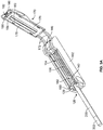
- Machine 100 includes a base 102 and a sliding member 104 that is mounted to the base 102 as will be described below.
- Sliding member 104 has sidewalls 105 at its opposite lateral edges. The sidewalls have outwardly directed ribs 106.
- Base 102 in turn has upstanding opposite inner sidewalls 118 with inwardly directed ribs 120 near the bottom of each of the inner sidewalls. Ribs 120 define a slot 107 between the bottom surface of the ribs and a bottom wall 119 that is positioned in the bottom of the base as it is placed into the tobacco receiving cavity.
- Ribs 106 of the sliding member are dimensioned to be received in slots 107 to permit the sliding member to be moved proximally and distally in the base.
- the full range of movement of the sliding member is its "throw distance" between its initial distal loading position in which loose tobacco may be placed in the machine and its proximal filling in which tobacco is loaded into an empty tube. Once the cigarette tube is filled the sliding member is returned to its initial or distal loading position so that the tobacco filled cigarette tube may be removed from the machine.
- a concave spoon 108 is mounted to base 102 with a tobacco abutment member 110 positioned at the proximal end of the spoon.
- the spoon is designed to rest in a concave receiving surface of pin holder block 114 that is mounted in a receiving cavity 116 in bottom wall 119 of the base.
- the proximal end of the spoon is captured between tobacco abutment member 110 and pin holder block 114 and held in place by downwardly directed abutment pins 112 which pass through a pair of holes 109 in the spoon and are affixed in pin holder block 114.
- the abutment member includes a circular portion 113.
- the pin holder block 114 includes a distal surface 115 that cooperates with sliding member surface ( Figure 2 ) to limit proximal movement of the sliding member on the base.
- Inner sidewalls 118 of base 102 also include inwardly directed ribs 121 running along the top edges of the sidewalls. Inwardly directed ribs 121 limit lateral movement of the sliding member within the base as it moves proximally and distally therein.
- Base 102 also includes outer sidewalls 124 with elliptical depressions 124a to assist the user in grasping and holding the base.
- the base has a front end 126 with a cigarette tube clearance slot 128.
- a cigarette tube holding nipple assembly 132 is mounted in nipple assembly side rail receiving slots 140 in sliding member 104.
- the assembly includes a throughhole 134 and nipple side rails 136 that are received in slots 140.
- the assembly further includes a tube portion 137 dimensioned to be received in the open end of an empty cigarette paper tube 200 ( Figure 4A ) or 200a ( Figure 5E ) with a filter 202 at its distal end.
- Sliding member 104 has an inner generally rectangular tobacco receiving cavity 142 of adjustable length into which loose tobacco will be placed by a user before compressing and transferring the tobacco into the empty filter-tipped cigarette tube, as will be explained below.
- the tobacco receiving cavity has a circular bottom surface 143 ( Figure 5A ) abutting the bottom surface of spoon 108.
- Tobacco receiving cavity 142 includes downwardly directed curved inner walls 144 which help direct the loose tobacco into the bottom of the tobacco receiving cavity as it is placed into the tobacco receiving cavity and lightly compressed, as appropriate, before closing pivoting top member 170.
- distal movement of the sliding member on the base is a limited by engagement between abutment surface 147 of the sliding member and abutment end 149 of base rib 121.
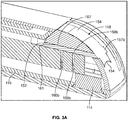
- Handheld cigarette making machine 100 includes an adjustment member 148 which is illustrated, inter alia, in Figures 1 , 2 and 3B-3C .
- Adjustment member 148 has a proximal end 150, a distal end 152, and hemispherical cut-outs 153 and 154 in its proximal distal and proximal end walls.
- the adjustment member also includes a convex, proximally facing top surface 155 and a generally flat distal abutment surface 156 above cut out 153.
- adjustment member 148 has outwardly directed ribs 157a and 157b and downwardly directed protuberances 158a and 158b ( Figure 3A ). When the adjustment member is in position in the sliding member, ribs 157a and 157b will be positioned in slots 167 of sliding member sidewalls 105 to enable the adjustment member to be moved proximately and distally in sliding member 104.
- Adjustment member 148 insures that the amount of loose tobacco 142 will correspond to the empty tobacco-receiving portion of the cigarette tube chosen.
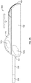
- Handheld cigarette making machine 100 has a top pivoting member 170 ( Figure 1 ) with a pair of rearwardly directed pivot arms 172. Member 170 is attached to sliding member 104 for pivoting movement with respect to the sliding member. An elongated downwardly directed cigarette tamping member 178 is located on the bottom surface 176 of pivoting top member 170 as can be seen, for example, in Figure 5A .
- the tamping member has a concave elongated lower surface 180 of a single length corresponding to the shorter pre-determined length of tobacco receiving cavity 142 when the adjustment member is in its distal position, as will be explained below.
- a downwardly directed elastomeric cigarette tube holding member 182 is also positioned on bottom surface 176 ( Figure 5A ).
- This elastomeric cigarette tube holding member has a concave surface 184 positioned to engage the outer surface of the open end of a cigarette tube when it is mounted to nipple tube portion 137 to prevent the tube from pulling away from the machine as compressed tobacco is being moved into the tube.
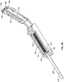
- Cigarette making machine 100 is shown in a bottom perspective view in Figure 2 , with bottom wall 119 of base 102 removed to facilitate viewing of adjustment member 148 in a pre-assembly position.
- adjustment member 148 When the adjustment member is assembled in the sliding member, its ribs 157a and 157b will be positioned in slots 167 of sliding member sidewalls 105.
- This view also shows proximal vertically oriented protuberance-receiving slots 159a and 159b and vertically oriented distal protuberance-receiving slots 160a and 160b in internal sidewalls 146 of sliding member 104.
- slots receive protuberances 158a and 158b as adjustment member 148 is moved between its proximal and distal positions acting as temporary stops for the sliding member in its proximal and distal positions. Since the protuberances are rounded, the slots resist movement of the adjustment member only until a user applies sufficient force to move the rounded edges of the protuberances up along an edge of the slot to displace the protuberances from the pair of slots in which they are then resting and moved into engagement with the other pair of slots.
- This view also illustrates downwardly directed adjustment member stop 162 which abuts the inner surface 163 of proximal wall 165 of the sliding member when the adjustment member is in its proximal position with protuberances 158a and 158b sitting in proximal protuberance-receiving slots 159a and 159b.
- outwardly directed adjustment member ribs 157a and 157b will abut endpoints 169 of slots 167, to prevent distal movement beyond this point.
- Stops 171 which project inwardly from sliding member internal sidewalls 146 further limit distal movement of the adjustment member by engaging the protuberances adjacent to distal protuberance receiving slots 169a and 169b.
- Figure 3A shows adjustment member 148 in its proximal position which, as will be explained below, will enable the machine to accommodate and fill the longer of two cigarette tube lengths.
- top surface 155 of the adjustment number is flush with the corresponding proximal contour of the sliding member which prevents any inadvertent movement of the adjustment member during the handling of the machine.
- Protuberances 158a (not shown in this view) and 158b rest in the top edge of corresponding slots 159a (not shown in this view) and 159b in sidewalls 146.
- Distal end 152 of the sliding member includes a flat distal abutment surface 156 as shown which extends into cavity 142 of the sliding member ( Figure 5A ) to act as a movable proximal end of the cavity to enable adjustment of the length of the cavity.
- the cavity is in its larger longitudinal dimension for filling a longer cigarette/cigarette tube.
- adjustment member 148 distally until it reaches and is locked in its most distal position. This can be done by pressing the proximally facing top surface 155 of the adjustment member with the tip of the user's finger 206 as shown in Figure 5C to apply force to overcome the resistance of the protuberances resting in proximal slots 159a and 159b to thereby move the adjustment member to the position illustrated in Figure 3B . As can be seen in this figure, protuberances 158a and 158b have been moved into engagement with the top edges of slots 160a and 160b.
- Figures 4 , 5A and 5B show cigarette machine 100 with an empty cigarette tube 200 mounted to the machine.
- Tube 200 has a filter 202 at its distal end which engages tobacco inserted into the tube at its proximal end, acting as a backstop to facilitate compaction of the tobacco as it is moved into the empty portion of the tube by the machine.
- top pivoting member 170 is shown pivoted away from sliding member 104 to reveal empty tobacco receiving cavity 142.
- Adjustment member 148 is in its proximal position so that the tobacco receiving aperture is in its larger or elongated longitudinal configuration and ready to receive a sufficient amount of loose tobacco to fill the longer portion of empty cigarette tube 200.
- Distal face 111 of abutment member 110 cooperates with distal end 152 of the adjustment member to close off or form the proximal end of the tobacco receiving cavity in this configuration.
- Figure 5B shows the same view, but with loose tobacco 204 generally filling the tobacco receiving cavity.
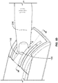
- the loose cigarette tobacco in cavity 142 may be tamped in place with a tool like tamper accessory 210 which is illustrated in Figure 6 .
- Tamper accessory 210 is particularly adapted for use with machine 10 since it includes opposed tamping edges 212 and 214 of two different lengths corresponding to the two different lengths of tobacco receiving cavity 142 obtained by moving adjustment member 148 between its proximal and distal positions to fill two different cigarette tube tobacco-receiving portion lengths.
- the tamper accessory may be gripped by the user placing his/her thumb and forefinger on opposite sides of the tamper midsection 216 while orienting the appropriately sized tamper edge opposite the loose tobacco in the cavity and manipulating and compressing the loose tobacco to ensure that an appropriate amount of tobacco will be available to fill the empty portion of the cigarette tube.
- a user will press the proximally facing top surface 155 of adjustment member 148 distally, moving it to its most distal position, thereby reconfiguring tobacco receiving cavity 142 to its smaller longitudinal configuration as shown in Figures 5D and 5E .
- cigarette tube 200a with the shorter empty portion will be affixed to nipple tube portion 137 of the machine.
- loose tobacco will be placed in the shortened empty cavity as illustrated in Figure 5F to fill the shorter empty portion of cigarette tube 200a.
- adjustment member 148 is pressed distally as shown in Figure 5D and the process proceeds as described above.
- the amount of tobacco loaded into tobacco receiving cavity 142 is limited by the shortening of that cavity which extends to the distally displaced distal end 152 of the adjustment member.
- the two different cigarette tube empty portions can be filled by this machine using a single throw distance corresponding to the movement of the sliding member from its rest position of Figures 4 , 5A and 5B and the full fill position of Figure 5G.
- a properly filled cigarette tube will be obtained without any adjustment in the throw distance of the sliding member.
- a base 218 which may be used with hand-held cigarette making machine 10 is illustrated in Figure 7 .
- the base is made from an elastomeric material like TPE rubber which is resilient and has a high coefficient of friction, although it may be made from any appropriate material.
- base 218 is configured to accept and be used with machine 10, it may be configured to accept and be used with any handheld cigarette making machine that is designed to be loaded with loose tobacco from the top and to longitudinally draw an empty cigarette tube over a compressed cylinder of tobacco formed by the machine.
- Base 218 includes an elongated machine-receiving cavity 220 with lateral inner sidewalls 222 and 224, a back wall 226 and a front wall 228.
- Front wall 228 includes a preferably circular passage 230 dimensioned and positioned to enable a cigarette tube to move across the front wall during the tube filling process.
- Base 218 has a support surface 232, lateral outer sidewalls 234 and 236 as well as a rear end wall 238 and a front end wall 240. It is preferred that the outer sidewalls, rear end wall and front end wall are angled away from machine-receiving cavity 220 to increase the size and hence surface area of support surface 232 to thereby increase the stability of the base. It is also preferred that outer sidewalls 234 and 236 be generally inwardly rounded as shown to facilitate gripping of the base during operation of the machine. Finally, the lateral outer sidewalls 234 and 236 include elliptical gripping areas 242 with raised lines as shown to facilitate gripping of the base during the operation of the machine.
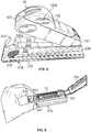
- Insertion of machine 10 into base 218 is illustrated in Figure 8 .
- the proximal end 101 of the machine may be inserted into base machine-receiving cavity 220 first and the machine is rotated downwardly. The downward motion of the machine is continued until the distal end 103 of the machine is fully received in the cavity. Insertion may alternatively begin at the distal end of the machine.
- the retention of the machine in the base is enhanced by the friction between sidewalls 222 and 224 as well as back in front walls 226 and 228 and the corresponding outer surfaces of the machine.
- base 218 of the assembly may be placed on a tabletop or other appropriate support surface 242 ( Figure 10 ) where it will remain during the introduction of the tobacco and the tube filling operation.
- the base is made of an elastomeric material
- the enhanced coefficient of friction of bottom surface 232 on the tabletop or other appropriate support surface helps minimize sliding of the assembly further enhancing the operation of the combined tabletop base and machine assembly.
- FIG 9 machine 10 mounted in base 218 is shown with pivoting top member 170 open, as in Figures 5A and 5E above, prior to insertion of loose tobacco into the tobacco receiving cavity of the machine as depicted in Figures 5B and 5F .
- the user may conveniently grip base 218 at gripping areas 242.
- the pivoting top member is closed and the machine is ready to be operated as depicted in Figure 4B above.
- the user conveniently grips base 236 at eliptical gripping areas 242 which stabilizes the tabletop base and machine assembly while the user also grips the machine at depressions 124b of the sliding member and moves the sliding member distally to draw cigarette tube 200 along the prepared and waiting tobacco within the machine, as explained above.
Landscapes
- Packaging Of Annular Or Rod-Shaped Articles, Wearing Apparel, Cassettes, Or The Like (AREA)
- Cigarettes, Filters, And Manufacturing Of Filters (AREA)
- Vending Machines For Individual Products (AREA)
- Manufacturing Of Cigar And Cigarette Tobacco (AREA)
Priority Applications (1)
| Application Number | Priority Date | Filing Date | Title |
|---|---|---|---|
| PL17190642T PL3300615T3 (pl) | 2016-09-12 | 2017-09-12 | Podręczne urządzenie do wytwarzania papierosów |
Applications Claiming Priority (1)
| Application Number | Priority Date | Filing Date | Title |
|---|---|---|---|
| US15/262,527 US10231480B1 (en) | 2016-09-12 | 2016-09-12 | Handheld cigarette-making machine |
Publications (3)
| Publication Number | Publication Date |
|---|---|
| EP3300615A2 EP3300615A2 (en) | 2018-04-04 |
| EP3300615A3 EP3300615A3 (en) | 2018-06-20 |
| EP3300615B1 true EP3300615B1 (en) | 2020-03-11 |
Family
ID=59858584
Family Applications (1)
| Application Number | Title | Priority Date | Filing Date |
|---|---|---|---|
| EP17190642.3A Active EP3300615B1 (en) | 2016-09-12 | 2017-09-12 | Hand-held cigarette-making machine |
Country Status (8)
| Country | Link |
|---|---|
| US (1) | US10231480B1 (pl) |
| EP (1) | EP3300615B1 (pl) |
| CN (1) | CN107811325B (pl) |
| AU (1) | AU2017228516C1 (pl) |
| CA (1) | CA2978911C (pl) |
| ES (1) | ES2784460T3 (pl) |
| HU (1) | HUE049208T2 (pl) |
| PL (1) | PL3300615T3 (pl) |
Families Citing this family (6)
| Publication number | Priority date | Publication date | Assignee | Title |
|---|---|---|---|---|
| USD881464S1 (en) * | 2017-07-05 | 2020-04-14 | Republic Tobacco L.P. | Cigarette making machine |
| CN110547501B (zh) | 2018-05-31 | 2022-06-10 | 共和品牌集团 | 由位于机器一侧的把手可操作的手动制香烟机 |
| JP7252349B2 (ja) * | 2019-05-31 | 2023-04-04 | ジェイティー インターナショナル エス.エイ. | 管状スリーブにカット植物材料を充填するためのデバイス及び方法 |
| USD952938S1 (en) | 2020-08-18 | 2022-05-24 | Republic Brands L.P. | Cigarette-making machine |
| EP4029385A1 (en) * | 2021-01-14 | 2022-07-20 | JT International SA | Manual cigarette making device with flavour application |
| CN113519891B (zh) * | 2021-08-04 | 2022-05-24 | 胡阳兵 | 一种药膳香烟及其制备方法和设备 |
Family Cites Families (5)
| Publication number | Priority date | Publication date | Assignee | Title |
|---|---|---|---|---|
| DE4110830C1 (pl) | 1991-04-04 | 1992-05-27 | Gizeh-Werk Gmbh, 5275 Bergneustadt, De | |
| FR2847429B1 (fr) | 2002-11-25 | 2006-06-23 | Republic Technologies Na Llc | Machine a garnir des tubes de cigarettes ayant differentes longueurs |
| CA2424881A1 (en) | 2003-04-08 | 2004-10-08 | Ctc Canada Inc. | Convertible compact cigarette making machine |
| DE202008012816U1 (de) | 2008-09-26 | 2010-03-04 | Gizeh Raucherbedarf Gmbh | Vorrichtung zum Stopfen von Zigarettenhülsen |
| DE202012102605U1 (de) | 2012-07-13 | 2013-10-14 | Gizeh Raucherbedarf Gmbh | Vorrichtung zum Stopfen von Zigarettenhülsen |
-
2016
- 2016-09-12 US US15/262,527 patent/US10231480B1/en active Active
-
2017
- 2017-09-11 CA CA2978911A patent/CA2978911C/en active Active
- 2017-09-11 AU AU2017228516A patent/AU2017228516C1/en active Active
- 2017-09-12 ES ES17190642T patent/ES2784460T3/es active Active
- 2017-09-12 HU HUE17190642A patent/HUE049208T2/hu unknown
- 2017-09-12 PL PL17190642T patent/PL3300615T3/pl unknown
- 2017-09-12 EP EP17190642.3A patent/EP3300615B1/en active Active
- 2017-09-12 CN CN201710818857.8A patent/CN107811325B/zh active Active
Non-Patent Citations (1)
| Title |
|---|
| None * |
Also Published As
| Publication number | Publication date |
|---|---|
| EP3300615A3 (en) | 2018-06-20 |
| AU2017228516C1 (en) | 2019-12-12 |
| HUE049208T2 (hu) | 2020-09-28 |
| CN107811325B (zh) | 2021-05-11 |
| ES2784460T3 (es) | 2020-09-25 |
| EP3300615A2 (en) | 2018-04-04 |
| PL3300615T3 (pl) | 2020-06-29 |
| CA2978911C (en) | 2019-12-31 |
| CA2978911A1 (en) | 2018-03-12 |
| CN107811325A (zh) | 2018-03-20 |
| AU2017228516B2 (en) | 2019-07-25 |
| US10231480B1 (en) | 2019-03-19 |
| AU2017228516A1 (en) | 2018-03-29 |
Similar Documents
| Publication | Publication Date | Title |
|---|---|---|
| EP3300615B1 (en) | Hand-held cigarette-making machine | |
| AU2007200694B2 (en) | Cigarette-making machine | |
| US3491768A (en) | Cigarette making apparatus | |
| US4771793A (en) | Compact cigarette making machine | |
| US7905235B2 (en) | Cigarette rolling machine | |
| JP2000516487A (ja) | ばね付勢された変形可能な眼内レンズ注入装置 | |
| EP2328430B1 (en) | Cigarette rolling and forming devices | |
| US20160058068A1 (en) | Tabletop automatic cigarette-making machine | |
| US6978789B2 (en) | Convertible compact cigarette making machine | |
| CN102164514B (zh) | 用于填塞烟管的装置 | |
| JP7429814B2 (ja) | 前部及び後部変位機構を連行するハンドルを有するインジェクタ | |
| CN110547501B (zh) | 由位于机器一侧的把手可操作的手动制香烟机 | |
| US4632129A (en) | Cigarette making machine | |
| US20130192612A1 (en) | Illuminated cigarette rolling and forming devices | |
| US20200375242A1 (en) | Cigarette-rolling kit system and method | |
| CN106723328A (zh) | 一种滑动式细支卷烟烟丝填充装置 | |
| HU219101B (hu) | Eljárás és berendezés cigarettapapír-hüvelyek dohánnyal való megtöltésére, illetve megtömésére, valamint dohánnyal töltött törzshüvelyek | |
| EP1512334A1 (de) | Stopfvorrichtung zur Selbstfertigung von Zigaretten | |
| HK1109840A (en) | Cigarette-making machine |
Legal Events
| Date | Code | Title | Description |
|---|---|---|---|
| PUAI | Public reference made under article 153(3) epc to a published international application that has entered the european phase |
Free format text: ORIGINAL CODE: 0009012 |
|
| STAA | Information on the status of an ep patent application or granted ep patent |
Free format text: STATUS: THE APPLICATION HAS BEEN PUBLISHED |
|
| AK | Designated contracting states |
Kind code of ref document: A2 Designated state(s): AL AT BE BG CH CY CZ DE DK EE ES FI FR GB GR HR HU IE IS IT LI LT LU LV MC MK MT NL NO PL PT RO RS SE SI SK SM TR |
|
| AX | Request for extension of the european patent |
Extension state: BA ME |
|
| PUAL | Search report despatched |
Free format text: ORIGINAL CODE: 0009013 |
|
| AK | Designated contracting states |
Kind code of ref document: A3 Designated state(s): AL AT BE BG CH CY CZ DE DK EE ES FI FR GB GR HR HU IE IS IT LI LT LU LV MC MK MT NL NO PL PT RO RS SE SI SK SM TR |
|
| AX | Request for extension of the european patent |
Extension state: BA ME |
|
| RIC1 | Information provided on ipc code assigned before grant |
Ipc: A24C 5/42 20060101AFI20180511BHEP |
|
| STAA | Information on the status of an ep patent application or granted ep patent |
Free format text: STATUS: REQUEST FOR EXAMINATION WAS MADE |
|
| 17P | Request for examination filed |
Effective date: 20181105 |
|
| RBV | Designated contracting states (corrected) |
Designated state(s): AL AT BE BG CH CY CZ DE DK EE ES FI FR GB GR HR HU IE IS IT LI LT LU LV MC MK MT NL NO PL PT RO RS SE SI SK SM TR |
|
| STAA | Information on the status of an ep patent application or granted ep patent |
Free format text: STATUS: EXAMINATION IS IN PROGRESS |
|
| 17Q | First examination report despatched |
Effective date: 20190125 |
|
| GRAP | Despatch of communication of intention to grant a patent |
Free format text: ORIGINAL CODE: EPIDOSNIGR1 |
|
| STAA | Information on the status of an ep patent application or granted ep patent |
Free format text: STATUS: GRANT OF PATENT IS INTENDED |
|
| RIC1 | Information provided on ipc code assigned before grant |
Ipc: A24C 5/06 20060101ALI20190926BHEP Ipc: A24C 5/42 20060101AFI20190926BHEP |
|
| INTG | Intention to grant announced |
Effective date: 20191025 |
|
| GRAS | Grant fee paid |
Free format text: ORIGINAL CODE: EPIDOSNIGR3 |
|
| GRAA | (expected) grant |
Free format text: ORIGINAL CODE: 0009210 |
|
| STAA | Information on the status of an ep patent application or granted ep patent |
Free format text: STATUS: THE PATENT HAS BEEN GRANTED |
|
| AK | Designated contracting states |
Kind code of ref document: B1 Designated state(s): AL AT BE BG CH CY CZ DE DK EE ES FI FR GB GR HR HU IE IS IT LI LT LU LV MC MK MT NL NO PL PT RO RS SE SI SK SM TR |
|
| REG | Reference to a national code |
Ref country code: GB Ref legal event code: FG4D |
|
| REG | Reference to a national code |
Ref country code: CH Ref legal event code: EP |
|
| REG | Reference to a national code |
Ref country code: AT Ref legal event code: REF Ref document number: 1242038 Country of ref document: AT Kind code of ref document: T Effective date: 20200315 |
|
| REG | Reference to a national code |
Ref country code: IE Ref legal event code: FG4D |
|
| REG | Reference to a national code |
Ref country code: DE Ref legal event code: R096 Ref document number: 602017012840 Country of ref document: DE |
|
| REG | Reference to a national code |
Ref country code: NL Ref legal event code: FP |
|
| PG25 | Lapsed in a contracting state [announced via postgrant information from national office to epo] |
Ref country code: FI Free format text: LAPSE BECAUSE OF FAILURE TO SUBMIT A TRANSLATION OF THE DESCRIPTION OR TO PAY THE FEE WITHIN THE PRESCRIBED TIME-LIMIT Effective date: 20200311 Ref country code: RS Free format text: LAPSE BECAUSE OF FAILURE TO SUBMIT A TRANSLATION OF THE DESCRIPTION OR TO PAY THE FEE WITHIN THE PRESCRIBED TIME-LIMIT Effective date: 20200311 Ref country code: NO Free format text: LAPSE BECAUSE OF FAILURE TO SUBMIT A TRANSLATION OF THE DESCRIPTION OR TO PAY THE FEE WITHIN THE PRESCRIBED TIME-LIMIT Effective date: 20200611 |
|
| PG25 | Lapsed in a contracting state [announced via postgrant information from national office to epo] |
Ref country code: HR Free format text: LAPSE BECAUSE OF FAILURE TO SUBMIT A TRANSLATION OF THE DESCRIPTION OR TO PAY THE FEE WITHIN THE PRESCRIBED TIME-LIMIT Effective date: 20200311 Ref country code: BG Free format text: LAPSE BECAUSE OF FAILURE TO SUBMIT A TRANSLATION OF THE DESCRIPTION OR TO PAY THE FEE WITHIN THE PRESCRIBED TIME-LIMIT Effective date: 20200611 Ref country code: GR Free format text: LAPSE BECAUSE OF FAILURE TO SUBMIT A TRANSLATION OF THE DESCRIPTION OR TO PAY THE FEE WITHIN THE PRESCRIBED TIME-LIMIT Effective date: 20200612 Ref country code: SE Free format text: LAPSE BECAUSE OF FAILURE TO SUBMIT A TRANSLATION OF THE DESCRIPTION OR TO PAY THE FEE WITHIN THE PRESCRIBED TIME-LIMIT Effective date: 20200311 Ref country code: LV Free format text: LAPSE BECAUSE OF FAILURE TO SUBMIT A TRANSLATION OF THE DESCRIPTION OR TO PAY THE FEE WITHIN THE PRESCRIBED TIME-LIMIT Effective date: 20200311 |
|
| REG | Reference to a national code |
Ref country code: LT Ref legal event code: MG4D |
|
| REG | Reference to a national code |
Ref country code: ES Ref legal event code: FG2A Ref document number: 2784460 Country of ref document: ES Kind code of ref document: T3 Effective date: 20200925 |
|
| REG | Reference to a national code |
Ref country code: HU Ref legal event code: AG4A Ref document number: E049208 Country of ref document: HU |
|
| PG25 | Lapsed in a contracting state [announced via postgrant information from national office to epo] |
Ref country code: CZ Free format text: LAPSE BECAUSE OF FAILURE TO SUBMIT A TRANSLATION OF THE DESCRIPTION OR TO PAY THE FEE WITHIN THE PRESCRIBED TIME-LIMIT Effective date: 20200311 Ref country code: PT Free format text: LAPSE BECAUSE OF FAILURE TO SUBMIT A TRANSLATION OF THE DESCRIPTION OR TO PAY THE FEE WITHIN THE PRESCRIBED TIME-LIMIT Effective date: 20200805 Ref country code: RO Free format text: LAPSE BECAUSE OF FAILURE TO SUBMIT A TRANSLATION OF THE DESCRIPTION OR TO PAY THE FEE WITHIN THE PRESCRIBED TIME-LIMIT Effective date: 20200311 Ref country code: IS Free format text: LAPSE BECAUSE OF FAILURE TO SUBMIT A TRANSLATION OF THE DESCRIPTION OR TO PAY THE FEE WITHIN THE PRESCRIBED TIME-LIMIT Effective date: 20200711 Ref country code: SK Free format text: LAPSE BECAUSE OF FAILURE TO SUBMIT A TRANSLATION OF THE DESCRIPTION OR TO PAY THE FEE WITHIN THE PRESCRIBED TIME-LIMIT Effective date: 20200311 Ref country code: SM Free format text: LAPSE BECAUSE OF FAILURE TO SUBMIT A TRANSLATION OF THE DESCRIPTION OR TO PAY THE FEE WITHIN THE PRESCRIBED TIME-LIMIT Effective date: 20200311 Ref country code: EE Free format text: LAPSE BECAUSE OF FAILURE TO SUBMIT A TRANSLATION OF THE DESCRIPTION OR TO PAY THE FEE WITHIN THE PRESCRIBED TIME-LIMIT Effective date: 20200311 Ref country code: LT Free format text: LAPSE BECAUSE OF FAILURE TO SUBMIT A TRANSLATION OF THE DESCRIPTION OR TO PAY THE FEE WITHIN THE PRESCRIBED TIME-LIMIT Effective date: 20200311 |
|
| REG | Reference to a national code |
Ref country code: DE Ref legal event code: R097 Ref document number: 602017012840 Country of ref document: DE |
|
| PLBE | No opposition filed within time limit |
Free format text: ORIGINAL CODE: 0009261 |
|
| STAA | Information on the status of an ep patent application or granted ep patent |
Free format text: STATUS: NO OPPOSITION FILED WITHIN TIME LIMIT |
|
| PG25 | Lapsed in a contracting state [announced via postgrant information from national office to epo] |
Ref country code: DK Free format text: LAPSE BECAUSE OF FAILURE TO SUBMIT A TRANSLATION OF THE DESCRIPTION OR TO PAY THE FEE WITHIN THE PRESCRIBED TIME-LIMIT Effective date: 20200311 Ref country code: IT Free format text: LAPSE BECAUSE OF FAILURE TO SUBMIT A TRANSLATION OF THE DESCRIPTION OR TO PAY THE FEE WITHIN THE PRESCRIBED TIME-LIMIT Effective date: 20200311 |
|
| 26N | No opposition filed |
Effective date: 20201214 |
|
| PG25 | Lapsed in a contracting state [announced via postgrant information from national office to epo] |
Ref country code: SI Free format text: LAPSE BECAUSE OF FAILURE TO SUBMIT A TRANSLATION OF THE DESCRIPTION OR TO PAY THE FEE WITHIN THE PRESCRIBED TIME-LIMIT Effective date: 20200311 |
|
| REG | Reference to a national code |
Ref country code: CH Ref legal event code: PL |
|
| PG25 | Lapsed in a contracting state [announced via postgrant information from national office to epo] |
Ref country code: CH Free format text: LAPSE BECAUSE OF NON-PAYMENT OF DUE FEES Effective date: 20200930 Ref country code: LI Free format text: LAPSE BECAUSE OF NON-PAYMENT OF DUE FEES Effective date: 20200930 Ref country code: IE Free format text: LAPSE BECAUSE OF NON-PAYMENT OF DUE FEES Effective date: 20200912 |
|
| REG | Reference to a national code |
Ref country code: LU Ref legal event code: HC Owner name: REPUBLIC BRANDS L.P.; US Free format text: FORMER OWNER: REPUBLIC TOBACCO L.P. Effective date: 20210913 |
|
| REG | Reference to a national code |
Ref country code: ES Ref legal event code: PC2A Owner name: REPUBLIC BRANDS L.P Effective date: 20211215 |
|
| REG | Reference to a national code |
Ref country code: DE Ref legal event code: R081 Ref document number: 602017012840 Country of ref document: DE Owner name: REPUBLIC BRANDS L.P., GLENVIEW, US Free format text: FORMER OWNER: REPUBLIC TOBACCO L.P., GLENVIEW, ILL., US |
|
| REG | Reference to a national code |
Ref country code: BE Ref legal event code: HC Owner name: REPUBLIC BRANDS L.P.; US Free format text: DETAILS ASSIGNMENT: CHANGE OF OWNER(S), CHANGE OF OWNER(S) NAME; FORMER OWNER NAME: REPUBLIC TOBACCO L.P. Effective date: 20211108 |
|
| REG | Reference to a national code |
Ref country code: AT Ref legal event code: HC Ref document number: 1242038 Country of ref document: AT Kind code of ref document: T Owner name: REPUBLIC BRANDS L.P., US Effective date: 20220119 |
|
| REG | Reference to a national code |
Ref country code: NL Ref legal event code: HC Owner name: REPUBLIC BRANDS L.P.; US Free format text: DETAILS ASSIGNMENT: CHANGE OF OWNER(S), CHANGE OF OWNER(S) NAME; FORMER OWNER NAME: REPUBLIC TOBACCO L.P. Effective date: 20220329 |
|
| PG25 | Lapsed in a contracting state [announced via postgrant information from national office to epo] |
Ref country code: MT Free format text: LAPSE BECAUSE OF FAILURE TO SUBMIT A TRANSLATION OF THE DESCRIPTION OR TO PAY THE FEE WITHIN THE PRESCRIBED TIME-LIMIT Effective date: 20200311 Ref country code: CY Free format text: LAPSE BECAUSE OF FAILURE TO SUBMIT A TRANSLATION OF THE DESCRIPTION OR TO PAY THE FEE WITHIN THE PRESCRIBED TIME-LIMIT Effective date: 20200311 |
|
| PG25 | Lapsed in a contracting state [announced via postgrant information from national office to epo] |
Ref country code: MK Free format text: LAPSE BECAUSE OF FAILURE TO SUBMIT A TRANSLATION OF THE DESCRIPTION OR TO PAY THE FEE WITHIN THE PRESCRIBED TIME-LIMIT Effective date: 20200311 Ref country code: MC Free format text: LAPSE BECAUSE OF FAILURE TO SUBMIT A TRANSLATION OF THE DESCRIPTION OR TO PAY THE FEE WITHIN THE PRESCRIBED TIME-LIMIT Effective date: 20200311 Ref country code: AL Free format text: LAPSE BECAUSE OF FAILURE TO SUBMIT A TRANSLATION OF THE DESCRIPTION OR TO PAY THE FEE WITHIN THE PRESCRIBED TIME-LIMIT Effective date: 20200311 |
|
| P01 | Opt-out of the competence of the unified patent court (upc) registered |
Effective date: 20231009 |
|
| REG | Reference to a national code |
Ref country code: AT Ref legal event code: UEP Ref document number: 1242038 Country of ref document: AT Kind code of ref document: T Effective date: 20200311 |
|
| PGFP | Annual fee paid to national office [announced via postgrant information from national office to epo] |
Ref country code: DE Payment date: 20250929 Year of fee payment: 9 |
|
| PGFP | Annual fee paid to national office [announced via postgrant information from national office to epo] |
Ref country code: PL Payment date: 20250822 Year of fee payment: 9 Ref country code: TR Payment date: 20250822 Year of fee payment: 9 Ref country code: LU Payment date: 20250929 Year of fee payment: 9 Ref country code: NL Payment date: 20250926 Year of fee payment: 9 |
|
| PGFP | Annual fee paid to national office [announced via postgrant information from national office to epo] |
Ref country code: HU Payment date: 20250822 Year of fee payment: 9 Ref country code: BE Payment date: 20250929 Year of fee payment: 9 Ref country code: GB Payment date: 20250929 Year of fee payment: 9 |
|
| PGFP | Annual fee paid to national office [announced via postgrant information from national office to epo] |
Ref country code: AT Payment date: 20250929 Year of fee payment: 9 Ref country code: FR Payment date: 20250925 Year of fee payment: 9 |
|
| PGFP | Annual fee paid to national office [announced via postgrant information from national office to epo] |
Ref country code: ES Payment date: 20251001 Year of fee payment: 9 |