EP3300339A1 - Topologiebasierte internetprotokoll (ip)-adressierung - Google Patents
Topologiebasierte internetprotokoll (ip)-adressierung Download PDFInfo
- Publication number
- EP3300339A1 EP3300339A1 EP17186386.3A EP17186386A EP3300339A1 EP 3300339 A1 EP3300339 A1 EP 3300339A1 EP 17186386 A EP17186386 A EP 17186386A EP 3300339 A1 EP3300339 A1 EP 3300339A1
- Authority
- EP
- European Patent Office
- Prior art keywords
- group
- address
- local network
- devices
- identifier
- Prior art date
- Legal status (The legal status is an assumption and is not a legal conclusion. Google has not performed a legal analysis and makes no representation as to the accuracy of the status listed.)
- Granted
Links
- 238000000034 method Methods 0.000 claims abstract description 58
- 238000004891 communication Methods 0.000 claims description 14
- 230000001052 transient effect Effects 0.000 claims description 12
- 230000005540 biological transmission Effects 0.000 claims description 2
- 239000003999 initiator Substances 0.000 abstract description 39
- 230000008569 process Effects 0.000 abstract description 37
- 238000011144 upstream manufacturing Methods 0.000 description 16
- 238000004519 manufacturing process Methods 0.000 description 8
- 230000006870 function Effects 0.000 description 6
- 230000009471 action Effects 0.000 description 3
- 230000008859 change Effects 0.000 description 3
- 238000011161 development Methods 0.000 description 3
- 238000010586 diagram Methods 0.000 description 3
- 230000000644 propagated effect Effects 0.000 description 3
- 238000012986 modification Methods 0.000 description 2
- 230000004048 modification Effects 0.000 description 2
- 230000006855 networking Effects 0.000 description 2
- 239000000356 contaminant Substances 0.000 description 1
- 238000013480 data collection Methods 0.000 description 1
- 230000001934 delay Effects 0.000 description 1
- 230000003111 delayed effect Effects 0.000 description 1
- 230000007613 environmental effect Effects 0.000 description 1
- 230000008676 import Effects 0.000 description 1
- 230000010354 integration Effects 0.000 description 1
- 238000005259 measurement Methods 0.000 description 1
- 238000012806 monitoring device Methods 0.000 description 1
- 238000012544 monitoring process Methods 0.000 description 1
- 238000004886 process control Methods 0.000 description 1
- 230000010076 replication Effects 0.000 description 1
- 238000012163 sequencing technique Methods 0.000 description 1
- 230000035939 shock Effects 0.000 description 1
- 230000003068 static effect Effects 0.000 description 1
Images


Classifications
-
- H—ELECTRICITY
- H04—ELECTRIC COMMUNICATION TECHNIQUE
- H04L—TRANSMISSION OF DIGITAL INFORMATION, e.g. TELEGRAPHIC COMMUNICATION
- H04L61/00—Network arrangements, protocols or services for addressing or naming
- H04L61/50—Address allocation
- H04L61/5007—Internet protocol [IP] addresses
- H04L61/5014—Internet protocol [IP] addresses using dynamic host configuration protocol [DHCP] or bootstrap protocol [BOOTP]
-
- H—ELECTRICITY
- H04—ELECTRIC COMMUNICATION TECHNIQUE
- H04L—TRANSMISSION OF DIGITAL INFORMATION, e.g. TELEGRAPHIC COMMUNICATION
- H04L61/00—Network arrangements, protocols or services for addressing or naming
- H04L61/50—Address allocation
- H04L61/5038—Address allocation for local use, e.g. in LAN or USB networks, or in a controller area network [CAN]
-
- H—ELECTRICITY
- H04—ELECTRIC COMMUNICATION TECHNIQUE
- H04L—TRANSMISSION OF DIGITAL INFORMATION, e.g. TELEGRAPHIC COMMUNICATION
- H04L41/00—Arrangements for maintenance, administration or management of data switching networks, e.g. of packet switching networks
- H04L41/12—Discovery or management of network topologies
-
- H—ELECTRICITY
- H04—ELECTRIC COMMUNICATION TECHNIQUE
- H04L—TRANSMISSION OF DIGITAL INFORMATION, e.g. TELEGRAPHIC COMMUNICATION
- H04L2101/00—Indexing scheme associated with group H04L61/00
- H04L2101/60—Types of network addresses
- H04L2101/618—Details of network addresses
- H04L2101/622—Layer-2 addresses, e.g. medium access control [MAC] addresses
-
- H—ELECTRICITY
- H04—ELECTRIC COMMUNICATION TECHNIQUE
- H04L—TRANSMISSION OF DIGITAL INFORMATION, e.g. TELEGRAPHIC COMMUNICATION
- H04L45/00—Routing or path finding of packets in data switching networks
- H04L45/02—Topology update or discovery
-
- H—ELECTRICITY
- H04—ELECTRIC COMMUNICATION TECHNIQUE
- H04L—TRANSMISSION OF DIGITAL INFORMATION, e.g. TELEGRAPHIC COMMUNICATION
- H04L45/00—Routing or path finding of packets in data switching networks
- H04L45/74—Address processing for routing
- H04L45/741—Routing in networks with a plurality of addressing schemes, e.g. with both IPv4 and IPv6
-
- H—ELECTRICITY
- H04—ELECTRIC COMMUNICATION TECHNIQUE
- H04L—TRANSMISSION OF DIGITAL INFORMATION, e.g. TELEGRAPHIC COMMUNICATION
- H04L61/00—Network arrangements, protocols or services for addressing or naming
-
- H—ELECTRICITY
- H04—ELECTRIC COMMUNICATION TECHNIQUE
- H04L—TRANSMISSION OF DIGITAL INFORMATION, e.g. TELEGRAPHIC COMMUNICATION
- H04L61/00—Network arrangements, protocols or services for addressing or naming
- H04L61/09—Mapping addresses
- H04L61/10—Mapping addresses of different types
-
- H—ELECTRICITY
- H04—ELECTRIC COMMUNICATION TECHNIQUE
- H04L—TRANSMISSION OF DIGITAL INFORMATION, e.g. TELEGRAPHIC COMMUNICATION
- H04L61/00—Network arrangements, protocols or services for addressing or naming
- H04L61/50—Address allocation
- H04L61/5092—Address allocation by self-assignment, e.g. picking addresses at random and testing if they are already in use
-
- H—ELECTRICITY
- H04—ELECTRIC COMMUNICATION TECHNIQUE
- H04W—WIRELESS COMMUNICATION NETWORKS
- H04W84/00—Network topologies
- H04W84/18—Self-organising networks, e.g. ad-hoc networks or sensor networks
Definitions
- the present invention relates to the field of industrial control systems, and more particularly, to a system and method for assigning Internet Protocol (IP) addresses to industrial control devices in a local network group.
- IP Internet Protocol
- Industrial controllers are specialized computer systems used for the control of industrial processes or machinery, for example, in a factory environment.
- an industrial controller executes a stored control program that reads inputs from a variety of sensors associated with the controlled process or machine and, sensing the conditions of the process or machine, and based on those inputs and a stored control program, calculates a set of outputs used to control actuators controlling the process or machine.
- Special control languages such as "relay ladder logic" are normally used to facilitate programming of the device.
- a processor of the industrial controller periodically examines the state of input devices and updates the state of output devices. In order to ensure predictable control of a machine or process, the control program must be highly reliable and deterministic, that is, executing at well-defined time periods.
- Industrial controllers differ from conventional computers in a number of ways. Physically, they are constructed to be substantially more robust against shock and damage and to better resist external contaminants and extreme environmental conditions than conventional computers.
- the processors and operating systems are optimized for real-time control and are programmed with languages designed to permit rapid development of control programs tailored to a constantly varying set of machine control or process control applications.
- control networks suitable for highly reliable and available real-time communication.
- control networks for example, EtherNet/IP, DeviceNet and ControlNet
- industrial controllers may employ I/O modules or devices dedicated to a particular type of electrical signal and function, for example, detecting input AC or DC signals or controlling output AC or DC signals.
- I/O modules or devices may have a connector system allowing them to be installed in different combinations in a housing or rack along with other selected I/O modules or devices to match the demands of the particular application.
- Multiple or individual I/O modules or devices may be located at convenient control points near the controlled process or machine to communicate with a central industrial controller via the control network.
- Control networks may employ "connected messaging” in which the bandwidth of the network and buffer space is pre-allocated to dedicated "connections” to detect lost or unpredictably delayed data control message transfers or to guarantee client/server transaction integrity as in common Ethernet usage.
- An example of connected messaging is embodied within Common Industrial Protocol (CIP), which is a media independent industrial protocol for industrial automation applications supported by the Open DeviceNet Vendors Association (ODVA).
- CIP is described in " The Common Industrial Protocol (CIP) and the Family of CIP Networks," Copyright 2006. Open DeviceNet Vendor Association, Inc. . which document is incorporated herein by reference in its entirety.
- CIP encompasses a comprehensive suite of messages and services for the collection of manufacturing automation applications, including control, safety, synchronization, motion, configuration and other information.
- Application extensions to CIP include: CIP Safety, providing a communication between nodes such as safety I/O blocks, safety interlock switches, safety light curtains and safety PLC's in safety applications up to Safety Integrity Level (SIL) 3 according to IEC 61508 standards; CIP Motion, allowing integration of field devices and motion drives on the same network thereby eliminating the need for a separate motion optimized network; and CIP Sync, a time synchronization extension to CIP based on the recent IEEE-1588 standard - Precision Clock Synchronization Protocol for Networked Measurement and Control Systems - providing increased control coordination for sequencing demanding events recording, distributed motion control and other distributed applications.
- CIP maximizes compatibility among devices in an industrial system, and typical control networks implementing CIP include EtherNet/IP, DeviceNct, ControlNet and similar networks whose specifications are published and whose protocols are used broadly by a number of manufacturers and
- IP Internet Protocol
- EtherNet/IP EtherNet/IP network
- Constrained devices are devices typically having limited power, computational capability, memory, communication rates or are otherwise resource constrained, and in some instances, may be devices that are battery powered. Examples of constrained devices may include electronic overload relays, pushbuttons, contactors, proximity sensors and other I/O elements.
- constrained devices might not have received IP addresses at all.
- the constrained nature of such devices often prevents the ability to support Dynamic Host Configuration Protocol (DHCP) or Bootstrap Protocol software, or to support hardware switches for static IP address assignment, and as a result, inhibits IP address assignment via existing addressing methods altogether.
- DHCP Dynamic Host Configuration Protocol
- Bootstrap Protocol software may still be undesirable in industrial control systems as DHCP assignments generally inhibit maintaining fixed IP addresses for specific devices, which is often an important function in industrial control systems.
- devices may also be configured in parts of the system according to different network topologies, such as linear, ring and/or star topologies.
- network topologies such as linear, ring and/or star topologies.
- constrained devices are usually present in large amounts.
- assigning IP addresses to each individual device such as by using DHCP software or hardware switches where feasible, may be inefficient and/or ineffective due to, for example, the need for increased time to set up the network, difficulty in ensuring IP address uniqueness, and the like.
- the possibility of applying changes to the system, including updating hardware or software, replacing devices, and so forth also complicates maintaining a fault tolerant addressing scheme.
- IP addresses may be allocated to devices in an industrial control system by applying starting address information in combination with each device's relative position in a local network.
- the starting address information which may include an IP subnet address, gateway address, subnet mask, subnet size, and/or local network group identifier, may be provided to a first positioned, or "initiator," device in a local network.
- the initiator device may determine its IP address by applying the starting address information and knowledge of being the first positioned device.
- the initiator device may send the position information and at least a portion of the starting address information to a next device, which may determine its relative position based on the received position information, and which may apply its relative position with the portion of the starting address information to determine its IP address. This process may continue sequentially for each device in the local network until each device has an IP address.
- IP addresses may be assigned to a wider variety of devices, including constrained devices. Also, network device changes may be more quickly resolved.
- a first device in the group may function as an "initiator" device.
- the initiator device may be provided with global network information.
- the initiator device may then execute a position-based sequential IP addressing process.
- the Network ID, Group ID and updateable GDID may be provided to every device via addressing command messages.
- Each device may then generate its GDID based on its position in the network. With a determined GDID, each device may then also determine an IP address according to the Network ID, the Group ID and its GDID taken together.
- topology information (which may include a list of devices with corresponding IP addresses, MAC addresses, device ID's and/or position ID's and/or a total number of devices) and/or "status information” (which may communicate a topology change and/or device fault in the group, if any) may be returned as an addressing result to each of the devices via an "addressing complete message.”
- IPv4 Internet Protocol version 4
- IPv6 Internet Protocol version 6
- the network may be divided according to "sub-networks" and "groups."
- Sub-networks may be collections of devices which connect through a common switch in the network.
- Groups may be a collection of devices which locally connect to one another in a "sub-network.”
- Each group may implement its own topology, such as: (1) a linear topology in which devices physically connect one after another in a daisy chain; (2) a ring topology in which devices physically connect one after another to form a closed loop; or (3) a star topology in which each device physically connects point to point with a common connection point.
- topologies of groups may differ from one another in a single network.
- IP address assignment according to the present invention may be useful in instances where a new network is being commissioned, a portion of the network is being updated or upgraded, and/or one or more devices of the network are being replaced.
- IP addresses may be generated based on the physical topology of groups.
- the IP addresses may consists of (1) a "Network ID” / "network information” (which may be assigned by the router for the connected subnet, and which may include a gateway address, subnet mask, subnet ID or prefix (e.g., 192.168.1), and subnet size (e.g., 256)); (2) a "Group ID” / "group information” (which may be assigned by the switch for the group, and which may include a group ID and/or group size); and (3) a “Group Device ID” (GDID) (which may be based on a device's position in the group relative to a first device in the group functioning as an "initiator” device for the linear or ring topology, or which port of a common connection point the device may be connected to for the star topology).
- GDID Group Device ID
- a first device in the group may function as an "initiator" device.
- the initiator device may be provided with start address information, including the Network ID, the Group ID and a starting GDID.
- the start address information could come from a switch, a remote DHCP server, or a user tool.
- a user could set up a group size (number of devices in the network group) and a device's IP parameters (IP Address, Net Mask, Gateway address, and so forth) with a user tool to generate the start address information.
- the initiator device may then execute a position-based sequential IP addressing process which may be commanded by a user via a hardware or software interface.
- the IP addressing process may allow, among other things: (1) addressing all devices in a network for a newly commissioned system; (2) addressing newly added devices in a network, such as for a system upgrade; and/or (3) addressing replaced devices in a network, such as for a faulted device replacement.
- the addressing process may be executed, for example, via layer-2 addressing messages (the data link layer of the well-known seven-layer Open Systems Interconnection (OSI) model for computer networking).
- the Network ID, Group ID and updatcable GDID may be provided to every device via addressing command messages. Each device may then generate its GDID based on its position in the network.
- each device may then also determine an IP address according to the Network ID, the Group ID and its GDID taken together.
- the "topology information” (which may include a list of devices with corresponding IP addresses, MAC addresses, device ID's and/or position ID's and/or a total number of devices) and/or "status information” (which may communicate a topology change and/or device fault in the group, if any) may be returned as an addressing result to each of the devices via an "addressing complete message.”
- Other devices in the system such as workstations, controllers, and the like, may retrieve such information for different purposes, such as to display the topology, set IP addresses in an industrial controller's configuration, and so forth.
- the initiator device may access or receive a Network ID, Group ID and starting GDID.
- the initiator device could be, for example, an industrial controller accessing a default Network ID, Group ID and/or starting GDID stored locally in the device.
- the initiator device could also be, for example, a common managed industrial network switch accessing multiple sets of Network ID, Group ID and/or starting GDID stored locally for different groups. Applying the aforementioned sequential IP address assignment process, the initiator device may determine a starting IP address from the Network ID, Group ID and starting GDID.
- the initiator device may then forward the Network ID, Group ID and GDID to a next device in the group in an "addressing command message.”
- the next device may receive the "addressing command message” and determine its GDID based on its position in the network relative to the initiator.
- the next device may then also determine its IP address based on the Network ID, Group ID and its GDID taken together.
- the next device may then forward the Network ID, Group ID and its GDID (updated) to its next device in the group, continuing the "addressing command message.” This sequence continues through each device until all of the devices in the group have determined a GDID and IP address.
- the "topology information" and/or “status information” may be returned through the devices in the group to complete the IP address assignment via the "addressing complete message.”
- an upstream element may access or receive a Network ID, Group ID and/or starting GDID.
- the upstream element could be, for example, a common managed network switch for the sub-network accessing a default Network ID, Group ID and/or starting GDID stored locally in the switch.
- the upstream element for example, a common switch for the sub-network, may store multiple sets of Network ID, Group ID and/or starting GDID for different initiators.
- the upstream element may provide the Network ID, Group ID and/or starting GDID to the initiator device.
- the initiator device may apply the aforementioned sequential IP address assignment process, including sending the "addressing command messages" and receiving the "addressing complete message.” as described above with respect to Concept 1.
- an upstream element may access or receive a Network ID, Group ID and/or starting GDID.
- the upstream element could be, for example, a common managed network switch for the sub-network accessing a default Network ID, Group ID and/or starting GDID stored locally in the switch.
- the upstream element for example, a common switch for the sub-network, may store multiple sets of Network ID, Group ID and/or starting GDID for different initiators.
- the upstream element may implement a DHCP server for allocating IP addresses based on an optional Network ID, optional Group ID and/or GDID taken together for devices in the group.
- the upstream element may provide the Network ID, Group ID and/or starting GDID to the initiator device.
- the initiator device may apply the aforementioned sequential IP address assignment process, including sending the "addressing command message” and receiving the "addressing complete message,” as described above with respect to Concept 1.
- each next device may communicate its determined GDID to the upstream element implementing the DHCP server, and the upstream element implementing the DHCP server may determine the IP address for the device and provide the device with an IP address and other "network information".
- an upstream element may access or receive a Network ID, Group ID and/or starting GDID.
- the upstream element could be, for example, a common managed network switch for the sub-network accessing a default Network ID, Group ID and/or starting GDID stored locally in the switch.
- the upstream element for example, a common switch for the sub-network, may store multiple sets of Network ID, Group ID and/or starting GDID for different initiators.
- a separate DHCP server may also be provided in the system for allocating IP addresses based on Network ID, Group ID and GDID taken together for devices in the group.
- the upstream element may provide an optional Network ID, Group ID and/or starting GDID to the initiator device.
- the initiator device may apply the aforementioned sequential IP address assignment process, including sending the "addressing command message” and receiving the "addressing complete message,” as described above with respect to Concept 1.
- each next device instead of each next device determining its IP address, each next device communicates its determined GDID and Group ID to the DHCP server, and the DHCP server may determine the IP address for the device and provide the device with an IP address and other "network information.”
- one aspect of the present invention provides a method for assigning Internet Protocol (IP) addresses to industrial control devices in a local network group connected to a switch, the local network group being part of an industrial control network connected to a router.
- the method may include: (a) providing starting address information to a first device in the local network group, the starting address information including: (i) an IP subnet address for the router; and (ii) a group device identifier for distinguishing the first device from other devices in the local network group, the group device identifier initially indicating that the first device is positioned first in the local network group;(b) sending an addressing command message from the first device to a second device in the local network group, the addressing command message including the IP subnet address and the group device identifier for the first device; (c) determining a position for the second device in the local network group and updating the group device identifier in the addressing command message to produce an updated group device identifier for the second device; and (d) determining an IP address for the second device by applying the
- Another aspect may provide an industrial control system including: a router; a switch connected to the router; and first and second devices connected in a local network group, the local network group being connected to the switch.
- the first device may be operable to receive starting address information including: (i) an IP subnet address for the router; and (ii) a group device identifier for distinguishing the first device from other devices in the local network group, the group device identifier initially indicating that the first device is positioned first in the local network group.
- the first device may be further operable to execute a program stored in a non-transient medium operable to send an addressing command message to the second device in the local network group, the addressing command message including the IP subnet address and the group device identifier for the first device.
- the second device may be operable to execute a program stored in a non-transient medium operable to: (a) determine a position for the second device in the local network group and update the group device identifier in the addressing command message to produce an updated group device identifier for the second device; and (b) determine an IP address for the second device by applying the IP subnet address and the updated group device identifier to produce the IP address.
- Another aspect may provide an industrial control system including: a router; a switch connected to the router; and first and second devices connected in a local network group, the local network group being connected to the switch, wherein the first device is operable to receive starting address information including: (i) an IP subnet address for the router; and (ii) a group device identifier for distinguishing the first device from other devices in the local network group, the group device identifier initially indicating that the first device is positioned first in the local network group.
- the first device may be further operable to execute a program stored in a non-transient medium operable to send an addressing command message to the second device in the local network group, the addressing command message including the IP subnet address and the group device identifier for the first device.
- the second device may be operable to execute a program stored in a non-transient medium operable to: (a) determine a position for the second device in the local network group and update the group device identifier in the addressing command message to produce an updated group device identifier for the second device; (b) send the updated group device identifier to an address assigning device for applying the IP subnet address and the updated group device identifier to produce an IP address; and (c) receive the IP address from the address assigning device.
- a program stored in a non-transient medium operable to: (a) determine a position for the second device in the local network group and update the group device identifier in the addressing command message to produce an updated group device identifier for the second device; (b) send the updated group device identifier to an address assigning device for applying the IP subnet address and the updated group device identifier to produce an IP address; and (c) receive the IP address from the address assigning device.
- a system may be provided in which a position for each device (relative to other devices) in a topology, and a corresponding device ID for each device, may be predetermined. Then, the predetermined position and corresponding device ID for each device may be compared to actual devices in a topology having preprogrammed device ID's and pre-assigned IP addresses. If the comparison produces a match, the pre-assigned IP addresses in the actual devices may be utilized. However, if the comparison does not produce a match, the condition may be reported for further action.
- IP address assignment according to the present invention may be useful in instances where a new network is being commissioned, a portion of the network is being updated or upgraded, and/or one or more devices of the network are being replaced. IP address assignment according to the present invention may advantageously avoid the need for reconfiguring IP address settings in industrial controller for each system when identical machines are installed in adjacent working cells.
- an industrial control program and device configuration for linear or ring topology portions of a system may be developed by a user offline with a configuration software, such as the Studio 5000 environment available from Rockwell Automation.
- a linear topology may be a topology in which devices physically connect one after another in a daisy chain.
- a ring topology may be a topology in which devices physically connect one after another to form a closed loop.
- the control program may allow operation of devices to control an industrial process using sensors and actuators as known in the art.
- the device configuration may reflect a predetermined position for each device (relative to other devices in the topology) and a corresponding predetermined device ID for each device.
- the predetermined device ID may preferably include one or more Common Industrial Protocol (CIP) product keys (such as a vendor ID, device ID, product code, major revision, minor revision, and the like), which may avoid the need for reconfiguring IP address settings in industrial controller for each system when identical machines are installed in adjacent working cells, though in other aspects a MAC address could be used.
- CIP Common Industrial Protocol
- a corresponding IP address for each device may be left open pending an assignment (e.g., set to "WaitForAutoSetting").
- the control program and device configuration may then be installed on an industrial controller connected to devices implementing a topology, and the industrial controller may hold the control program in an "idle" mode pending resolution of IP addresses for such devices.
- the industrial controller may then initiate an automatic device IP addressing process in which the industrial controller individually discovers and/or determines information from each device, such as: (1) each device's position in the topology (relative to other devices in the topology); (2) each device's device ID (such as a CIP product key or MAC address); and (3) each device's IP address assigned during the automatic device IP addressing process.
- This may be accomplished, for example, by the industrial controller communicating an "auto-IP command message" through each device in the linear chain and receiving an "auto-IP complete message.”
- the industrial controller compares the position and device ID discovered for each device with the predetermined position and device ID in the device configuration installed on the industrial controller.
- This comparison attempts to correlate identical positions of devices with identical corresponding device ID's between what has been predetermined in the device configuration and what has been discovered in the topology. If the predetermined topology information in the device configuration matches the discovered topology information, the industrial controller writes the device IP addresses to the device configuration, confirms the devices in the topology are available, and places the control program in a "run" mode for normal operations using the IP addresses to communicate with the devices in the topology. However, if the predetermined topology information in the device configuration does not match the discovered topology information, the industrial controller reports the condition to a user for further action.
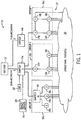
- FIG. 1 a block diagram of an exemplar industrial control system 10 which may implement a method for assigning Internet Protocol (IP) addresses to devices in the system is provided in accordance with an embodiment of the invention.
- the system 10 may include a router 12 which may connect to Wide Area Network (WAN) for connecting to other devices, such as another system similar to the system 10 and/or the Internet.
- WAN Wide Area Network
- the router 12 may be a networking device configured to forward data packets between industrial control networks.
- the router 12 may connect to one or more switches 14 (illustrated in FIG. 1 as switches 14a and 14b, corresponding to "Switch 1" and “Switch 2,” respectively, shown by way of example) in the system 10. Accordingly, each switch 14 may establish a IP sub-network in the system 10, such as "sub-network 1" associated with Switch 1. "sub network 2" associated with Switch 2, and so forth. Each switch 14, in turn, may connect to one or more local network groups 16 (illustrated in FIG. 1 as local network groups 16a, 16b and 16c, corresponding to "Group 1,” “Group 2” and “Group 3,” respectively, shown by way of example). Each local network group 16 may include multiple industrial control devices 18 (illustrated in FIG.
- Devices 18 may include industrial controllers, drives, I/O modules and the like, as well as constrained devices (which may have limited power, computational capability, memory, communication rates or be otherwise resource constrained), such as electronic overload relays, pushbuttons, contactors, proximity sensors and other I/O elements. Accordingly, devices 18 may include various connections 22 to sensors for sensing conditions of the process or machine 20 and/or actuators for controlling the industrial process or machine 20 as known in the art.
- the local network groups 16, within a sub-network may each implement a variety of network topologies, such as star, linear and/or ring topologies.
- the local network group 16a may include a switch or hub 19 for implementing a star topology with the devices 18a, 18b and 18c. Accordingly, the star topology may physically connect each of the devices 18a, 18b and 18c point to point with the switch or hub 19.
- the local network group 16b may implement a linear topology with the devices 18d, 18c and 18f. Accordingly, the linear topology may physically connect the devices 18d, 18c and 18f one after another in a daisy chain.
- the local network group 16c may implement a ring topology with the devices 18f, 18h, 18i and 18j. Accordingly, the ring topology may physically connect the devices 18f, 18h, 18i and 18j one after another to form a closed loop.
- the local network group 16c may employ a ring topology that is normally opened by a ring supervisor, such as device 18g (also identified in FIG. 1 as device "1"), at the ring supervisor.
- a ring supervisor such as device 18g (also identified in FIG. 1 as device "1"
- the ring supervisor may reconnect the ring to provide an alternative transmission path around the failure point.
- a computing device or server 26 may be provided in the system 10.
- the server 26 may connect to the switch 14a.
- the server 26 may have a processor executing a program stored in a non-transient medium to allow a user to provide control in the system 10, such as via a keyboard, monitor and/or other I/O as known in the art.
- the server 26 may implement a Dynamic Host Configuration Protocol (DHCP) program 28, as known in the art, for address assignment in the system 10 as will be further described.
- DHCP Dynamic Host Configuration Protocol
- the server 26 may implement the Studio 5000 environment available from Rockwell Automation and/or other program modules useful in the system 10, such as for providing start address information, developing an industrial control program, and/or developing a device configuration as will be further described.
- a Human Machine Interface (HMI) 30 may be provided in the system 10.
- the HMI 30 may connect to the switch 14a.
- the HMI 30 may have a processor executing a program stored in a non-transient medium to allow a user to provide control in the system 10 similar to the server 26.
- IP addresses may be assigned in accordance with an aspect of the invention.
- a first device in each of the groups such as device 18d in the local network group 16b, and/or device 18g in the local network group 16c, may function as an "initiator" device for the group.
- the initiator device may be provided with global network information. The initiator device may then execute a position-based sequential IP addressing process for subsequent devices in the group.
- a Network ID (“network identifier”), a Group ID (“group identifier”) and an updateable Group Device ID (GDID, or "group device identifier”) may be provided to every device in the group via addressing command messages.
- Each device may then generate its group device identifier based on its position in the network. With a determined group device identifier, each device may then also determine an IP address according to the network identifier, the group identifier and its group device identifier taken together.
- topology information (which may include a list of devices with corresponding IP addresses, MAC addresses, device ID's and/or position ID's and/or a total number of devices) and/or "status information” (which may communicate a topology change and/or device fault in the group, if any) may then be returned as an addressing result to each of the devices via an addressing complete message.
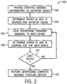
- FIG. 2 a flow chart illustrating an exemplar process 100 for assigning IP addresses is provided in accordance with an embodiment of the invention.
- the process 100 will be described by way of example with respect to the local network group 16b and the devices 18d, 18e and 18f. However, it will be appreciated that the process 100 or similar processes may be used in a variety of control network configurations having more or less devices 18 and varying network topologies, such as the local network group 16c and the devices 18g, 18h, 18i and 18j.
- starting address information may be provided to an initiator device, such as the first device 18d, in the local network group 16b.
- the starting address information may be provided, for example, by the switch 14a connected to the local network group 16b, the server 26 (which may implement a user tool), the HMI 30, or another upstream element.
- the starting address information may include a network identifier 120, a group identifier 122 and/or an updateable group device identifier 124.
- the network identifier 120 may include global network information for the system 10, which may originate from the router 12, including for example, an IP subnet address 120a or prefix (such as 192.168.1.0), an IP subnet size 120b (such as 256), an IP gateway address 120c (such as 0.0.0.0) and/or an IP subnet mask 120d (such as 255.255.255.00), as known in the art.
- the group identifier 122 may include group network information which may augment the global network information, including for example, a group identification number 122a (such as 0 or 1), which may correspond to the local network group 16a for distinguishing from other local network groups connected to the switch in the system 10, and/or a group size 122b (which may be equal to the IP subnet size).
- the group device identifier 124 may further augment the global network information by providing a unique device number based on a relative position for each device 18 in the local network group 16b.
- the group device identifier 124 may be updateable by each device 18 so that a relative position for each device in the local network group 16b may be provided.
- the starting address information may indicate that the initiator device, or first device 18d, is positioned first in the local network group 16 and is therefore an initiator device.
- the first device 18d may execute a program stored in a non-transient medium operable to determine its position in the local network group 16. relative to other devices 18 in the local network group 16b, by referencing the group device identifier 124 and/or the starting address information.
- the group device identifier 124 may be initially set to indicate that the first device 18d is positioned first in the local network group 16b.
- the first device 18d may acquire an IP address by applying an address assignment system 130, shown by way of example, or by communicating with another device applying the address assignment system 130.
- structure of the address assignment system 130 may be implemented, for example, in the devices 18, the server 26 (such as via the DHCP program 28) and/or the HMI 30, by hardware, software, or combination thereof.
- the address assignment system 130 at least a portion of the network identifier 120, such as the IP subnet address 120a, at least a portion of the group identifier 122, such as the group identification number 122a, and the group device identifier 124 may be applied to an applicator 132.
- the first device 18d may follow a direct path 134 to the applicator 132.
- the applicator 132 may apply the at least a portion of the network identifier 120, the at least a portion of the group identifier 122 and the group device identifier 124 to produce an IP address 136 for the first device 18d.
- the applicator 132 may implement summation logic.
- the first device 18d may further execute to send an addressing command message to the second device 18c in the local network group 16.
- the addressing command message may include the at least a portion of the network identifier 120, the at least a portion of the group identifier 122, and/or the group device identifier 124.
- the addressing command message may be communicated as an Open Systems Interconnection (OSI) model data link layer message as known in the art.
- OSI Open Systems Interconnection
- the second device 18e may execute a program stored in a non-transient medium operable to determine its position in the local network group 16b, relative to other devices 18 in the local network group 16b, and adjust the group device identifier 124.
- the second device 18e may determine its position and apply an adjustor 138 to adjust the group device identifier 124 to produce an updated group device identifier 124'.
- the adjustor 138 may increment the group device identifier 124. Accordingly, the goup device identifier 124 may follow an indirect path 140, through the adjustor 138, to the applicator 132.
- the applicator 132 may similarly apply the at least a portion of the network identifier 120, the at least a portion of the group identifier 122 and/or the updated group device identifier 124' to produce an IP address 136 for the second device 18e.
- the group device identifier 124 could be adjusted by the first device 18d before being sent to the second device 18e.
- the second device 18e it is determined whether the second device 18e is the last device in the local network group 16b. If the second device 18e is not the last device in the local network group ("NO" in FIG. 2 ), the second device 18e may further execute to send the addressing command message to a third device 18f, and the process may return to step 106.
- the third device 18f may similarly execute to determine its position, acquire an IP address, and so forth.
- the process may continue instead to step 112 in which an addressing complete message may be sent through each of the devices 18 in the local network group 16b.
- the addressing complete message may include a data collection for each device 18 in the local network group 16, corresponding to the position of the device 18, including for example, the IP address 136, a Media Access Control (MAC) address/ID and/or status field 144, the updated group device identifier 124' and/or a Common Industrial Protocol (CIP) identity object 146.
- IP IP address
- MAC Media Access Control
- CIP Common Industrial Protocol
- the CIP identity object 146 may provide an attribute for distinguishing a device 18 from among multiple devices 18, such as one or more of a Vendor ID, Device Type, Product Code and/or Serial Number, as described in " The Common Industrial Protocol (CIP) and the Family of CIP Networks," Copyright 2006, Open DeviceNet Vendor Association, Inc. , which document is incorporated herein by reference in its entirety.
- CIP Common Industrial Protocol
- the addressing complete message may also be communicated as an OSI model data link layer message as known in the art.
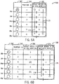
- a first column 162 may indicate devices 18 (shown by way of example as circles and identified as devices 18k through 18p in FIG. 6A ) in a local network group 16, such as in the system 10.
- the devices 18 may be in a linear or ring topology as illustrated by connections between the devices 18 in the table 160.
- the first device in the first column 162 (the device 18k also identified as "P1" in FIG. 6A ) may serve as an initiator device in the local network group.
- the first device could be, for example, an industrial controller, and in particular, a PLC, and if configured in a ring topology, could also be a ring supervisor.
- the remaining devices in the first column 162 could be, for example, industrial control devices, such as drives, I/O modules, constrained devices, and the like, which may be in communication with an industrial process or machine via sensors and/or actuators.
- a second column 164 may indicate an actual, relative position (or "Position ID") for each device 18 in the local network group.
- a third column 166 may indicate execution of an addressing process to produce group device identifiers (and in turn, IP addresses) in accordance with an embodiment of the invention.
- an addressing command message 170 may be propagated through the devices 18, the devices 18 may receive unique group identifiers, such as "1,” "2,” “3,” “4,” “5" and “6,” and an addressing complete message 172 may be returned through the devices 18.
- the group device identifier produced in the third column 166 may be equal to the Position ID in the second column 164.
- certain devices 18 may be upgraded or replaced as indicated in the first updated table 160'. This may include, for example, maintaining the same hardware while upgraded software and/or firmware, or replacing hardware with substantially similar hardware.
- the third column 166 may indicate that the third device 18m and the fifth device 18o have been changed (upgraded or replaced) and, as a result, the group device identifiers may be outdated.
- a fourth column 174 may indicate execution of a subsequent addressing process to produce updated group device identifiers (and in turn, IP addresses) in accordance with an embodiment of the invention.
- a subsequent addressing command message 176 may be propagated through the devices 18.
- Devices 18 which already have a group device identifier may retain their current group device identifier. However, the changed devices may each receive the same group device identifier previously assigned. Accordingly, the third device 18m may again receive the group device identifier "3,” and the fifth device 18o may again receive the group device identifier "5.” Finally, a subsequent addressing complete message 178 may be returned through the devices 18.
- new devices 180 may be added to the local network group 16 as indicated in the second updated table 160".
- a first new device 180a may be installed between the second and third devices 181 and 18m, respectively
- a second new device 180b may be installed between the fifth and sixth devices 18o and 18p, respectively
- a third new device 180c may be installed after the sixth device 18p. Accordingly, the Position ID's in the second column 164 have changed, and the group device identifiers in the third column 166 arc outdated.
- a fourth column 182 may indicate execution of a subsequent addressing process to produce updated group device identifiers (and in turn, IP addresses) in accordance with an embodiment of the invention.
- a subsequent addressing command message 184 may be propagated through the devices 18 and the new devices 180.
- Devices 18 which already have a group device identifier may retain their current group device identifier.
- the new devices 180 may each receive an adjusted group device identifier, which may be adjusted based on the last group device identifier to be assigned.
- the first new device encountered in the sequence which is the first new device 180a
- the second new device encountered in the sequence which is the second new device 180b
- the third new device encountered in the sequence which is the third new device 180c
- a subsequent addressing complete message 186 may be returned through the devices 18 and the devices 180. It will be appreciated that a combination of upgrading, replacing, adding and/or subtracting of devices may be provided, with device identifiers (and in turn, IP addresses) being updated, within the scope of the invention.
- a flow chart illustrating an exemplar process 200 for addressing devices in a local network group including an industrial controller which may be a PLC is provided in another aspect of the invention.
- a position for each device 18 (relative to other devices 18) in a topology, and a corresponding device ID for each device 18, may be predetermined.
- the predetermined position and corresponding device ID for each device may be compared to actual devices 18 in a topology having preprogrammed device ID's and pre-assigned IP addresses. If the comparison produces a match, the pre-assigned IP addresses in the actual devices may be utilized. However, if the comparison does not produce a match, the condition may be reported for further action.
- a device configuration may be developed offline, such as by a user operating the server 26 and/or the HMI 30, either of which may be executing the Studio 5000 environment, for providing a predetermined topology.
- the device configuration may predetermined relative positions for devices in a local network group, such as devices 18 in a local network group 16 of FIG. 1 , and may predetermined device identifiers corresponding to the predetermined relative positions, respectively.
- the predetermined device identifiers may provide attributes for distinguishing each of the devices from other devices.
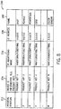
- an exemplar device configuration 230 is provided with parameters in tabular form.
- a first column 232 of the device configuration 230 may identify devices 18 in a linear or ring topology according to predetermined relative positions in a local network group. For example. "1" may refer to an initiator device or first device 18, while “n” may refer to a last device positioned in the topology.
- a second column 234 of the device configuration 230 may identify predetermined device identifiers (identified in FIG. 8 as "Product Key 1,'' "Product Key 2.'' and so forth) corresponding to the predetermined relative positions, respectively. The predetermined device identifiers may provide attributes for distinguishing devices from one another.
- a device identifier could be CIP identity object, such as a Vendor ID, Device Type, Product Code or Serial Number.
- CIP identity object such as a Vendor ID, Device Type, Product Code or Serial Number.
- other device identifiers capable of distinguishing industrial control devices from one another may be used within the scope of the invention.
- a third column 236 may indicate a current IP addressing mode for each device, which in the development environment may simply be waiting for an automatic IP address assignment configuration such as the method described above with respect to FIG. 2 .
- a fourth column 238 may indicate current IP addresses for each device, which in the development environment may simply be unassigned or default IP addresses.
- a fifth column 240 may indicate a name, function and/or any other useful parameter for each device.
- the device configuration may be provided to an industrial controller in a local network group that is believed to implement the predetermined topology, such as the device 18d of FIG. 1 or the device 18k of FIG. 6A .
- the local network group could be, for example, one of many replications of a working cell.
- an industrial control program may be developed offline, such as by a user operating the server 26 and/or the HMI 30, either of which may be executing the Studio 5000 environment, for controlling an industrial process or machine, such as the industrial process or machine 20.
- the control program may be configured to control devices in the local network group.
- the control program may also be being configured to reference the devices in the local network group using the device configuration, such as by referencing the predetermined relative positions in the first column 232 and/or the predetermined device identifiers in the second column 234.
- the control program After the control program is developed, it may also be provided to the industrial controller in the local network group believed to implement the predetermined topology.
- an addressing command message may be sent to the devices in the local network group.
- the addressing command message may be configured to generate IP addresses for the devices in the local network group and produce an addressing complete message.
- an addressing complete message may be received.
- the addressing complete message may provide, among other things, actual relative positions for the devices in the local network group, actual device identifiers corresponding to the actual relative positions, respectively; and IP addresses for the devices in the local network group.
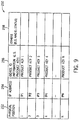
- the addressing complete message may provide an exemplar device collection 250 with parameters as illustrated in tabular form.
- a first column 252 of the device configuration 230 may identify devices 18 in a linear or ring topology according to actual relative positions for the devices in the local network group. For example, “1" may refer to an initiator device or first device 18, while “n” may refer to a last device positioned in the topology, as found in the system.
- a second column 254 may indicate currently assigned IP addresses for the devices, such as according to the method described above with respect to FIG. 2 .
- a third column 256 of the device configuration 230 may identify actual device identifiers (identified in FIG.
- a fourth column 258 may indicate Media Access Control (MAC) addresses/IDs and/or status fields for the devices and/or any other useful parameters as found in the system.
- MAC Media Access Control
- the process may continue to decision block 210 in which the predetermined topology, such as according to the device configuration 230, is compared to the actual topology, such as according to the device collection 250.
- the predetermined relative positions and the predetermined device identifiers from the predetermined topology may be compared to the actual relative positions and the actual device identifiers from the actual topology, respectively, to determine a match.
- the predetermined relative positions in the first column 232 and the predetermined device identifiers in the second column 234, each with respect to the device configuration 230 of FIG. 8 may be determined to match in order and content the actual relative positions in the first column 252 and the actual device identifiers in the third column 256, each with respect to the device collection 250 of FIG. 9 .
- the process 200 may continue to step 212 in which the industrial controller may accept the currently assigned IP addresses for the devices and begin executing the control program to control the devices in the local network group by using the currently assigned IP addresses corresponding to the devices. However, upon failing to determine a match ("NO" in FIG. 7 ), the process 200 may continue instead to step 214 in which the control program is prevented from executing and step 216 in which an alert message is sent to the user, such as via the server 26 and/or the HMI 30.
- references to "a microprocessor” and "a processor” or “the microprocessor” and “the processor” can be understood to include one or more microprocessors that can communicate in a stand-alone and/or a distributed environment(s), and can thus be configured to communicate via wired or wireless communications with other processors, where such one or more processors can be configured to operate on one or more processor-controlled devices that can be similar or different devices.
- references to memory can include one or more processor-readable and accessible memory elements and/or components that can be internal to the processor-controlled device, external to the processor-controlled device, and/or can be accessed via a wired or wireless network.
Landscapes
- Engineering & Computer Science (AREA)
- Computer Networks & Wireless Communication (AREA)
- Signal Processing (AREA)
- Small-Scale Networks (AREA)
Applications Claiming Priority (1)
| Application Number | Priority Date | Filing Date | Title |
|---|---|---|---|
| US15/271,591 US10412042B2 (en) | 2016-09-21 | 2016-09-21 | Topology based internet protocol (IP) addressing |
Publications (2)
| Publication Number | Publication Date |
|---|---|
| EP3300339A1 true EP3300339A1 (de) | 2018-03-28 |
| EP3300339B1 EP3300339B1 (de) | 2020-02-19 |
Family
ID=59799190
Family Applications (1)
| Application Number | Title | Priority Date | Filing Date |
|---|---|---|---|
| EP17186386.3A Active EP3300339B1 (de) | 2016-09-21 | 2017-08-16 | Topologiebasierte internetprotokoll (ip)-adressierung |
Country Status (3)
| Country | Link |
|---|---|
| US (1) | US10412042B2 (de) |
| EP (1) | EP3300339B1 (de) |
| CN (1) | CN107864230B (de) |
Cited By (2)
| Publication number | Priority date | Publication date | Assignee | Title |
|---|---|---|---|---|
| CN108712286A (zh) * | 2018-05-22 | 2018-10-26 | 华为技术有限公司 | 网络拓扑结构的确定方法、装置和存储介质 |
| LU102271B1 (de) * | 2020-11-27 | 2022-05-30 | Phoenix Contact Gmbh & Co | Zuweisungsverfahren zum Zuweisen von Geräte- Identifikationen und hierzu eingerichtetes Netzwerkgerät |
Families Citing this family (9)
| Publication number | Priority date | Publication date | Assignee | Title |
|---|---|---|---|---|
| US11288510B2 (en) * | 2017-09-15 | 2022-03-29 | Kimberly-Clark Worldwide, Inc. | Washroom device augmented reality installation system |
| GB2572982C (en) * | 2018-04-18 | 2021-01-20 | Gurulogic Microsystems Oy | System and method for creating group networks between network devices |
| EP3611876A1 (de) * | 2018-08-13 | 2020-02-19 | Siemens Aktiengesellschaft | Verfahren zur konfiguration, verfahren zur bereitstellung von topologie-informationen, verwendung, gerät, computerprogramm und computerlesbares medium |
| DE102019211843A1 (de) * | 2019-08-07 | 2021-02-11 | Kuka Deutschland Gmbh | Kommunikation mit automatisierbaren industriellen Vorrichtungen oder Anlagen oder mit deren Steuerung |
| US11277173B2 (en) * | 2019-10-15 | 2022-03-15 | Ricardo Matias De Goycoechea | Radio distribution system |
| CN110995483B (zh) * | 2019-11-29 | 2022-11-01 | 杭州迪普科技股份有限公司 | 网络拓扑的发现方法和装置 |
| US11483282B1 (en) * | 2021-12-10 | 2022-10-25 | Amazon Technologies, Inc. | Monitoring internet protocol address utilization to apply unified network policy |
| CN115604231B (zh) * | 2022-09-14 | 2024-08-09 | Oppo广东移动通信有限公司 | 网络地址的配置方法、路由设备、节点设备和存储介质 |
| US20240118676A1 (en) * | 2022-10-06 | 2024-04-11 | VirTeca, LLC | Segmented industrial control system architecture and related methods |
Citations (5)
| Publication number | Priority date | Publication date | Assignee | Title |
|---|---|---|---|---|
| DE19750470A1 (de) * | 1997-11-14 | 1999-06-02 | Woehr Otto Gmbh | Verfahren zur Adressierung von Baugruppensteuerungen einer Parkanlage für Kraftfahrzeuge |
| DE10038783A1 (de) * | 1999-08-25 | 2001-03-01 | Keba Ges M B H & Co Linz | Bussystem und Verfahren zur automatischen Adreßvergabe |
| US20100185784A1 (en) * | 2007-07-20 | 2010-07-22 | Nxp B.V. | Automatic address assignment for communiation bus |
| US20100274945A1 (en) * | 2009-04-27 | 2010-10-28 | Abl Ip Holding Llc | Automatic self-addressing method for wired network nodes |
| US8244838B2 (en) | 2009-03-30 | 2012-08-14 | Rockwell Automation Technologies, Inc. | Industrial controller employing the network ring topology |
Family Cites Families (16)
| Publication number | Priority date | Publication date | Assignee | Title |
|---|---|---|---|---|
| JP2000201183A (ja) * | 1999-01-08 | 2000-07-18 | Sony Corp | デ―タ送信方法 |
| US6801949B1 (en) * | 1999-04-12 | 2004-10-05 | Rainfinity, Inc. | Distributed server cluster with graphical user interface |
| US8032833B1 (en) * | 1999-07-27 | 2011-10-04 | Samsung Electronics Co., Ltd. | Home network device information architecture |
| ATE410875T1 (de) | 2004-01-23 | 2008-10-15 | Siemens Ag | Verfahren zur zuordnung einer ip-adresse zu einem gerät |
| US20070195729A1 (en) * | 2006-02-17 | 2007-08-23 | Hongbing Li | System and method for self-configuring adaptive wireless router network |
| US20080028865A1 (en) * | 2006-08-07 | 2008-02-07 | Steele David H | Portable Deflection Instrument for Testing Installed Planks |
| US20080288654A1 (en) * | 2007-05-17 | 2008-11-20 | Nokia Corporation | Node and method to provide and keep real-time up-to-date data in a distributed hash table |
| US8265144B2 (en) * | 2007-06-30 | 2012-09-11 | Microsoft Corporation | Innovations in video decoder implementations |
| US7885233B2 (en) * | 2007-07-31 | 2011-02-08 | Symbol Technologies, Inc. | Forwarding broadcast/multicast data when wireless clients layer 3 roam across IP subnets in a WLAN |
| US20090125637A1 (en) * | 2007-11-09 | 2009-05-14 | Nokia Corporation | Method, Apparatus and Computer Program Product for Providing Data Management in a P2P Network |
| WO2009071971A2 (en) * | 2007-12-05 | 2009-06-11 | Nokia Corporation | Method, apparatus, and computer program product for providing a smooth transition between peer-to-peer node types |
| CN101572692A (zh) * | 2008-04-28 | 2009-11-04 | 华为技术有限公司 | 一种ip地址分配方法、系统及设备 |
| EP2420907B1 (de) | 2010-08-16 | 2013-10-02 | Siemens Aktiengesellschaft | Verfahren zur Konfiguration von Feldbusteilnehmern |
| CN104506669B (zh) * | 2014-12-30 | 2018-02-16 | 中国科学院信息工程研究所 | 一种面向分布式网络仿真平台的ip地址分配系统及方法 |
| US9806970B2 (en) * | 2015-02-06 | 2017-10-31 | Crestron Electronics, Inc. | IP address conflict resolution system and method |
| US10110488B2 (en) * | 2015-04-23 | 2018-10-23 | Qualcomm Incorporated | Data link interface internet protocol (IP) address generation |
-
2016
- 2016-09-21 US US15/271,591 patent/US10412042B2/en active Active
-
2017
- 2017-08-16 EP EP17186386.3A patent/EP3300339B1/de active Active
- 2017-08-30 CN CN201710764124.0A patent/CN107864230B/zh active Active
Patent Citations (5)
| Publication number | Priority date | Publication date | Assignee | Title |
|---|---|---|---|---|
| DE19750470A1 (de) * | 1997-11-14 | 1999-06-02 | Woehr Otto Gmbh | Verfahren zur Adressierung von Baugruppensteuerungen einer Parkanlage für Kraftfahrzeuge |
| DE10038783A1 (de) * | 1999-08-25 | 2001-03-01 | Keba Ges M B H & Co Linz | Bussystem und Verfahren zur automatischen Adreßvergabe |
| US20100185784A1 (en) * | 2007-07-20 | 2010-07-22 | Nxp B.V. | Automatic address assignment for communiation bus |
| US8244838B2 (en) | 2009-03-30 | 2012-08-14 | Rockwell Automation Technologies, Inc. | Industrial controller employing the network ring topology |
| US20100274945A1 (en) * | 2009-04-27 | 2010-10-28 | Abl Ip Holding Llc | Automatic self-addressing method for wired network nodes |
Non-Patent Citations (1)
| Title |
|---|
| "The Common Industrial Protocol (CIP) and the Family of CIP Networks", 2006, OPEN DEVICENET VENDOR ASSOCIATION, INC. |
Cited By (3)
| Publication number | Priority date | Publication date | Assignee | Title |
|---|---|---|---|---|
| CN108712286A (zh) * | 2018-05-22 | 2018-10-26 | 华为技术有限公司 | 网络拓扑结构的确定方法、装置和存储介质 |
| LU102271B1 (de) * | 2020-11-27 | 2022-05-30 | Phoenix Contact Gmbh & Co | Zuweisungsverfahren zum Zuweisen von Geräte- Identifikationen und hierzu eingerichtetes Netzwerkgerät |
| WO2022112507A1 (de) * | 2020-11-27 | 2022-06-02 | Phoenix Contact Gmbh & Co.Kg | Zuweisungsverfahren zum zuweisen von geräte-identifikationen und hierzu eingerichtetes netzwerkgerät |
Also Published As
| Publication number | Publication date |
|---|---|
| US20180083917A1 (en) | 2018-03-22 |
| US10412042B2 (en) | 2019-09-10 |
| CN107864230A (zh) | 2018-03-30 |
| CN107864230B (zh) | 2020-08-11 |
| EP3300339B1 (de) | 2020-02-19 |
Similar Documents
| Publication | Publication Date | Title |
|---|---|---|
| EP3300339A1 (de) | Topologiebasierte internetprotokoll (ip)-adressierung | |
| EP3300338B1 (de) | Internetprotokoll (ip)-adressierung mittels eines industriellen steuerprogramms | |
| JP7009560B2 (ja) | プロセス制御システムに冗長性を提供するための方法および装置 | |
| US6982953B1 (en) | Automatic determination of correct IP address for network-connected devices | |
| EP1307823B1 (de) | Vernetzungssystem für die industrielle automatsieurung | |
| JP4271160B2 (ja) | 生産システムにおけるネットワーク開通方法 | |
| JP6419389B2 (ja) | 産業用オートメーションシステムのモジュール式制御装置の設定方法およびモジュール式制御装置 | |
| JP6665444B2 (ja) | 情報処理装置、情報処理装置の制御プログラム、制御方法及び情報処理システム | |
| US10735478B2 (en) | Controller and method for setting up communication links to redundantly operated controllers in an industrial automation system | |
| US10594551B2 (en) | Modular industrial automation device and method for configuring a modular industrial automation device | |
| US11669075B2 (en) | Automation device, computer program, computer-readable medium and method for automatically configuring an automation device | |
| KR20060121237A (ko) | 라우터 기능성을 자동으로 전송하는 방법 | |
| US11456992B2 (en) | Method for automatically configuring a router, method for automatic address configuration, router, computer program and computer-readable medium | |
| US11513483B2 (en) | Systems and methods for emulating a network device | |
| KR20080110216A (ko) | 동시 분산제어 및 독립제어 시스템 | |
| EP3761615A1 (de) | Verfahren zur automatischen belegung von steuergeräten und steuerbarer knoten in einem hierarchisches steuerungssystem |
Legal Events
| Date | Code | Title | Description |
|---|---|---|---|
| PUAI | Public reference made under article 153(3) epc to a published international application that has entered the european phase |
Free format text: ORIGINAL CODE: 0009012 |
|
| STAA | Information on the status of an ep patent application or granted ep patent |
Free format text: STATUS: THE APPLICATION HAS BEEN PUBLISHED |
|
| AK | Designated contracting states |
Kind code of ref document: A1 Designated state(s): AL AT BE BG CH CY CZ DE DK EE ES FI FR GB GR HR HU IE IS IT LI LT LU LV MC MK MT NL NO PL PT RO RS SE SI SK SM TR |
|
| AX | Request for extension of the european patent |
Extension state: BA ME |
|
| STAA | Information on the status of an ep patent application or granted ep patent |
Free format text: STATUS: REQUEST FOR EXAMINATION WAS MADE |
|
| 17P | Request for examination filed |
Effective date: 20180913 |
|
| RBV | Designated contracting states (corrected) |
Designated state(s): AL AT BE BG CH CY CZ DE DK EE ES FI FR GB GR HR HU IE IS IT LI LT LU LV MC MK MT NL NO PL PT RO RS SE SI SK SM TR |
|
| STAA | Information on the status of an ep patent application or granted ep patent |
Free format text: STATUS: EXAMINATION IS IN PROGRESS |
|
| 17Q | First examination report despatched |
Effective date: 20190227 |
|
| GRAP | Despatch of communication of intention to grant a patent |
Free format text: ORIGINAL CODE: EPIDOSNIGR1 |
|
| STAA | Information on the status of an ep patent application or granted ep patent |
Free format text: STATUS: GRANT OF PATENT IS INTENDED |
|
| INTG | Intention to grant announced |
Effective date: 20191007 |
|
| RAP1 | Party data changed (applicant data changed or rights of an application transferred) |
Owner name: ROCKWELL AUTOMATION TECHNOLOGIES, INC. |
|
| RIN1 | Information on inventor provided before grant (corrected) |
Inventor name: XU, DAYIN Inventor name: YU, YI Inventor name: BATKE, BRIAN A. Inventor name: WHITEHEAD, CLIFFORD J. Inventor name: BRANDT, DAVID |
|
| GRAS | Grant fee paid |
Free format text: ORIGINAL CODE: EPIDOSNIGR3 |
|
| GRAA | (expected) grant |
Free format text: ORIGINAL CODE: 0009210 |
|
| STAA | Information on the status of an ep patent application or granted ep patent |
Free format text: STATUS: THE PATENT HAS BEEN GRANTED |
|
| AK | Designated contracting states |
Kind code of ref document: B1 Designated state(s): AL AT BE BG CH CY CZ DE DK EE ES FI FR GB GR HR HU IE IS IT LI LT LU LV MC MK MT NL NO PL PT RO RS SE SI SK SM TR |
|
| REG | Reference to a national code |
Ref country code: CH Ref legal event code: EP |
|
| REG | Reference to a national code |
Ref country code: DE Ref legal event code: R096 Ref document number: 602017011882 Country of ref document: DE |
|
| REG | Reference to a national code |
Ref country code: AT Ref legal event code: REF Ref document number: 1236275 Country of ref document: AT Kind code of ref document: T Effective date: 20200315 |
|
| REG | Reference to a national code |
Ref country code: IE Ref legal event code: FG4D |
|
| REG | Reference to a national code |
Ref country code: NL Ref legal event code: MP Effective date: 20200219 |
|
| PG25 | Lapsed in a contracting state [announced via postgrant information from national office to epo] |
Ref country code: NO Free format text: LAPSE BECAUSE OF FAILURE TO SUBMIT A TRANSLATION OF THE DESCRIPTION OR TO PAY THE FEE WITHIN THE PRESCRIBED TIME-LIMIT Effective date: 20200519 Ref country code: RS Free format text: LAPSE BECAUSE OF FAILURE TO SUBMIT A TRANSLATION OF THE DESCRIPTION OR TO PAY THE FEE WITHIN THE PRESCRIBED TIME-LIMIT Effective date: 20200219 Ref country code: FI Free format text: LAPSE BECAUSE OF FAILURE TO SUBMIT A TRANSLATION OF THE DESCRIPTION OR TO PAY THE FEE WITHIN THE PRESCRIBED TIME-LIMIT Effective date: 20200219 |
|
| REG | Reference to a national code |
Ref country code: LT Ref legal event code: MG4D |
|
| PG25 | Lapsed in a contracting state [announced via postgrant information from national office to epo] |
Ref country code: IS Free format text: LAPSE BECAUSE OF FAILURE TO SUBMIT A TRANSLATION OF THE DESCRIPTION OR TO PAY THE FEE WITHIN THE PRESCRIBED TIME-LIMIT Effective date: 20200619 Ref country code: BG Free format text: LAPSE BECAUSE OF FAILURE TO SUBMIT A TRANSLATION OF THE DESCRIPTION OR TO PAY THE FEE WITHIN THE PRESCRIBED TIME-LIMIT Effective date: 20200519 Ref country code: HR Free format text: LAPSE BECAUSE OF FAILURE TO SUBMIT A TRANSLATION OF THE DESCRIPTION OR TO PAY THE FEE WITHIN THE PRESCRIBED TIME-LIMIT Effective date: 20200219 Ref country code: LV Free format text: LAPSE BECAUSE OF FAILURE TO SUBMIT A TRANSLATION OF THE DESCRIPTION OR TO PAY THE FEE WITHIN THE PRESCRIBED TIME-LIMIT Effective date: 20200219 Ref country code: SE Free format text: LAPSE BECAUSE OF FAILURE TO SUBMIT A TRANSLATION OF THE DESCRIPTION OR TO PAY THE FEE WITHIN THE PRESCRIBED TIME-LIMIT Effective date: 20200219 Ref country code: GR Free format text: LAPSE BECAUSE OF FAILURE TO SUBMIT A TRANSLATION OF THE DESCRIPTION OR TO PAY THE FEE WITHIN THE PRESCRIBED TIME-LIMIT Effective date: 20200520 |
|
| PG25 | Lapsed in a contracting state [announced via postgrant information from national office to epo] |
Ref country code: NL Free format text: LAPSE BECAUSE OF FAILURE TO SUBMIT A TRANSLATION OF THE DESCRIPTION OR TO PAY THE FEE WITHIN THE PRESCRIBED TIME-LIMIT Effective date: 20200219 |
|
| PG25 | Lapsed in a contracting state [announced via postgrant information from national office to epo] |
Ref country code: LT Free format text: LAPSE BECAUSE OF FAILURE TO SUBMIT A TRANSLATION OF THE DESCRIPTION OR TO PAY THE FEE WITHIN THE PRESCRIBED TIME-LIMIT Effective date: 20200219 Ref country code: CZ Free format text: LAPSE BECAUSE OF FAILURE TO SUBMIT A TRANSLATION OF THE DESCRIPTION OR TO PAY THE FEE WITHIN THE PRESCRIBED TIME-LIMIT Effective date: 20200219 Ref country code: ES Free format text: LAPSE BECAUSE OF FAILURE TO SUBMIT A TRANSLATION OF THE DESCRIPTION OR TO PAY THE FEE WITHIN THE PRESCRIBED TIME-LIMIT Effective date: 20200219 Ref country code: SK Free format text: LAPSE BECAUSE OF FAILURE TO SUBMIT A TRANSLATION OF THE DESCRIPTION OR TO PAY THE FEE WITHIN THE PRESCRIBED TIME-LIMIT Effective date: 20200219 Ref country code: RO Free format text: LAPSE BECAUSE OF FAILURE TO SUBMIT A TRANSLATION OF THE DESCRIPTION OR TO PAY THE FEE WITHIN THE PRESCRIBED TIME-LIMIT Effective date: 20200219 Ref country code: EE Free format text: LAPSE BECAUSE OF FAILURE TO SUBMIT A TRANSLATION OF THE DESCRIPTION OR TO PAY THE FEE WITHIN THE PRESCRIBED TIME-LIMIT Effective date: 20200219 Ref country code: SM Free format text: LAPSE BECAUSE OF FAILURE TO SUBMIT A TRANSLATION OF THE DESCRIPTION OR TO PAY THE FEE WITHIN THE PRESCRIBED TIME-LIMIT Effective date: 20200219 Ref country code: DK Free format text: LAPSE BECAUSE OF FAILURE TO SUBMIT A TRANSLATION OF THE DESCRIPTION OR TO PAY THE FEE WITHIN THE PRESCRIBED TIME-LIMIT Effective date: 20200219 Ref country code: PT Free format text: LAPSE BECAUSE OF FAILURE TO SUBMIT A TRANSLATION OF THE DESCRIPTION OR TO PAY THE FEE WITHIN THE PRESCRIBED TIME-LIMIT Effective date: 20200712 |
|
| REG | Reference to a national code |
Ref country code: AT Ref legal event code: MK05 Ref document number: 1236275 Country of ref document: AT Kind code of ref document: T Effective date: 20200219 |
|
| REG | Reference to a national code |
Ref country code: DE Ref legal event code: R097 Ref document number: 602017011882 Country of ref document: DE |
|
| PLBE | No opposition filed within time limit |
Free format text: ORIGINAL CODE: 0009261 |
|
| STAA | Information on the status of an ep patent application or granted ep patent |
Free format text: STATUS: NO OPPOSITION FILED WITHIN TIME LIMIT |
|
| 26N | No opposition filed |
Effective date: 20201120 |
|
| PG25 | Lapsed in a contracting state [announced via postgrant information from national office to epo] |
Ref country code: IT Free format text: LAPSE BECAUSE OF FAILURE TO SUBMIT A TRANSLATION OF THE DESCRIPTION OR TO PAY THE FEE WITHIN THE PRESCRIBED TIME-LIMIT Effective date: 20200219 Ref country code: AT Free format text: LAPSE BECAUSE OF FAILURE TO SUBMIT A TRANSLATION OF THE DESCRIPTION OR TO PAY THE FEE WITHIN THE PRESCRIBED TIME-LIMIT Effective date: 20200219 |
|
| PG25 | Lapsed in a contracting state [announced via postgrant information from national office to epo] |
Ref country code: SI Free format text: LAPSE BECAUSE OF FAILURE TO SUBMIT A TRANSLATION OF THE DESCRIPTION OR TO PAY THE FEE WITHIN THE PRESCRIBED TIME-LIMIT Effective date: 20200219 Ref country code: PL Free format text: LAPSE BECAUSE OF FAILURE TO SUBMIT A TRANSLATION OF THE DESCRIPTION OR TO PAY THE FEE WITHIN THE PRESCRIBED TIME-LIMIT Effective date: 20200219 |
|
| PG25 | Lapsed in a contracting state [announced via postgrant information from national office to epo] |
Ref country code: MC Free format text: LAPSE BECAUSE OF FAILURE TO SUBMIT A TRANSLATION OF THE DESCRIPTION OR TO PAY THE FEE WITHIN THE PRESCRIBED TIME-LIMIT Effective date: 20200219 |
|
| REG | Reference to a national code |
Ref country code: CH Ref legal event code: PL |
|
| PG25 | Lapsed in a contracting state [announced via postgrant information from national office to epo] |
Ref country code: CH Free format text: LAPSE BECAUSE OF NON-PAYMENT OF DUE FEES Effective date: 20200831 Ref country code: LI Free format text: LAPSE BECAUSE OF NON-PAYMENT OF DUE FEES Effective date: 20200831 Ref country code: LU Free format text: LAPSE BECAUSE OF NON-PAYMENT OF DUE FEES Effective date: 20200816 |
|
| REG | Reference to a national code |
Ref country code: BE Ref legal event code: MM Effective date: 20200831 |
|
| PG25 | Lapsed in a contracting state [announced via postgrant information from national office to epo] |
Ref country code: IE Free format text: LAPSE BECAUSE OF NON-PAYMENT OF DUE FEES Effective date: 20200816 Ref country code: BE Free format text: LAPSE BECAUSE OF NON-PAYMENT OF DUE FEES Effective date: 20200831 |
|
| REG | Reference to a national code |
Ref country code: DE Ref legal event code: R079 Ref document number: 602017011882 Country of ref document: DE Free format text: PREVIOUS MAIN CLASS: H04L0029120000 Ipc: H04L0067286900 |
|
| PG25 | Lapsed in a contracting state [announced via postgrant information from national office to epo] |
Ref country code: TR Free format text: LAPSE BECAUSE OF FAILURE TO SUBMIT A TRANSLATION OF THE DESCRIPTION OR TO PAY THE FEE WITHIN THE PRESCRIBED TIME-LIMIT Effective date: 20200219 Ref country code: MT Free format text: LAPSE BECAUSE OF FAILURE TO SUBMIT A TRANSLATION OF THE DESCRIPTION OR TO PAY THE FEE WITHIN THE PRESCRIBED TIME-LIMIT Effective date: 20200219 Ref country code: CY Free format text: LAPSE BECAUSE OF FAILURE TO SUBMIT A TRANSLATION OF THE DESCRIPTION OR TO PAY THE FEE WITHIN THE PRESCRIBED TIME-LIMIT Effective date: 20200219 |
|
| PG25 | Lapsed in a contracting state [announced via postgrant information from national office to epo] |
Ref country code: MK Free format text: LAPSE BECAUSE OF FAILURE TO SUBMIT A TRANSLATION OF THE DESCRIPTION OR TO PAY THE FEE WITHIN THE PRESCRIBED TIME-LIMIT Effective date: 20200219 Ref country code: AL Free format text: LAPSE BECAUSE OF FAILURE TO SUBMIT A TRANSLATION OF THE DESCRIPTION OR TO PAY THE FEE WITHIN THE PRESCRIBED TIME-LIMIT Effective date: 20200219 |
|
| P01 | Opt-out of the competence of the unified patent court (upc) registered |
Effective date: 20230404 |
|
| PGFP | Annual fee paid to national office [announced via postgrant information from national office to epo] |
Ref country code: GB Payment date: 20230720 Year of fee payment: 7 |
|
| PGFP | Annual fee paid to national office [announced via postgrant information from national office to epo] |
Ref country code: FR Payment date: 20230720 Year of fee payment: 7 Ref country code: DE Payment date: 20230720 Year of fee payment: 7 |