EP3300233A1 - Gleichstrom-elektromotor ohne wischblätter für scheibenreinigungssystem eines kraftfahrzeugs - Google Patents
Gleichstrom-elektromotor ohne wischblätter für scheibenreinigungssystem eines kraftfahrzeugs Download PDFInfo
- Publication number
- EP3300233A1 EP3300233A1 EP17182115.0A EP17182115A EP3300233A1 EP 3300233 A1 EP3300233 A1 EP 3300233A1 EP 17182115 A EP17182115 A EP 17182115A EP 3300233 A1 EP3300233 A1 EP 3300233A1
- Authority
- EP
- European Patent Office
- Prior art keywords
- electric motor
- layers
- axial
- multipole
- multipolar
- Prior art date
- Legal status (The legal status is an assumption and is not a legal conclusion. Google has not performed a legal analysis and makes no representation as to the accuracy of the status listed.)
- Granted
Links
- 230000005405 multipole Effects 0.000 claims abstract description 54
- 230000005355 Hall effect Effects 0.000 claims description 13
- 230000005284 excitation Effects 0.000 claims description 5
- 230000005415 magnetization Effects 0.000 claims description 2
- BGPVFRJUHWVFKM-UHFFFAOYSA-N N1=C2C=CC=CC2=[N+]([O-])C1(CC1)CCC21N=C1C=CC=CC1=[N+]2[O-] Chemical compound N1=C2C=CC=CC2=[N+]([O-])C1(CC1)CCC21N=C1C=CC=CC1=[N+]2[O-] BGPVFRJUHWVFKM-UHFFFAOYSA-N 0.000 description 6
- 230000007704 transition Effects 0.000 description 5
- 238000000926 separation method Methods 0.000 description 2
- 244000007853 Sarothamnus scoparius Species 0.000 description 1
- 241001080024 Telles Species 0.000 description 1
- 230000003247 decreasing effect Effects 0.000 description 1
- 238000009434 installation Methods 0.000 description 1
- 238000012544 monitoring process Methods 0.000 description 1
Images

Classifications
-
- H—ELECTRICITY
- H02—GENERATION; CONVERSION OR DISTRIBUTION OF ELECTRIC POWER
- H02K—DYNAMO-ELECTRIC MACHINES
- H02K29/00—Motors or generators having non-mechanical commutating devices, e.g. discharge tubes or semiconductor devices
- H02K29/06—Motors or generators having non-mechanical commutating devices, e.g. discharge tubes or semiconductor devices with position sensing devices
- H02K29/08—Motors or generators having non-mechanical commutating devices, e.g. discharge tubes or semiconductor devices with position sensing devices using magnetic effect devices, e.g. Hall-plates, magneto-resistors
-
- B—PERFORMING OPERATIONS; TRANSPORTING
- B60—VEHICLES IN GENERAL
- B60S—SERVICING, CLEANING, REPAIRING, SUPPORTING, LIFTING, OR MANOEUVRING OF VEHICLES, NOT OTHERWISE PROVIDED FOR
- B60S1/00—Cleaning of vehicles
- B60S1/02—Cleaning windscreens, windows or optical devices
- B60S1/04—Wipers or the like, e.g. scrapers
- B60S1/06—Wipers or the like, e.g. scrapers characterised by the drive
- B60S1/08—Wipers or the like, e.g. scrapers characterised by the drive electrically driven
-
- H—ELECTRICITY
- H02—GENERATION; CONVERSION OR DISTRIBUTION OF ELECTRIC POWER
- H02K—DYNAMO-ELECTRIC MACHINES
- H02K11/00—Structural association of dynamo-electric machines with electric components or with devices for shielding, monitoring or protection
- H02K11/20—Structural association of dynamo-electric machines with electric components or with devices for shielding, monitoring or protection for measuring, monitoring, testing, protecting or switching
- H02K11/21—Devices for sensing speed or position, or actuated thereby
- H02K11/215—Magnetic effect devices, e.g. Hall-effect or magneto-resistive elements
-
- H—ELECTRICITY
- H02—GENERATION; CONVERSION OR DISTRIBUTION OF ELECTRIC POWER
- H02K—DYNAMO-ELECTRIC MACHINES
- H02K2211/00—Specific aspects not provided for in the other groups of this subclass relating to measuring or protective devices or electric components
- H02K2211/03—Machines characterised by circuit boards, e.g. pcb
Definitions
- the subject of the invention is a brushless direct current electric motor for a motor vehicle wiper system.
- Such an electric motor mainly comprises a rotor and a stator.
- the stator comprises a plurality of electromagnetic excitation coils of the rotor while the rotor comprises a multipole magnet, in particular a magnet comprising two opposite magnetic poles, north and south.
- the electric motor is configured so that when the coils are energized with electric current, a magnetic field is created, causing a rotational movement of the multipolar magnet about an axis of rotation.
- the electric motor is also provided with a device for determining the position of the rotor, which makes it possible to ensure an electronic commutation of the supply of the coils according to the angle of the rotor, thus avoiding the presence of of brooms.
- the installation of the brushless electric motor in a wiper system for a motor vehicle needs to take into account spatial constraints since it is desirable to reduce as much as possible the size of the electric motor.
- the size of the multipolar magnet can not be decreased because, for a magnet narrow multipole, position sensors do not work properly and are not capable of detecting magnetic pole transitions of the magnet reliably.
- the object of the invention is to remedy at least partially this disadvantage.
- the subject of the invention is a brushless direct current electric motor for a motor vehicle wiper system, comprising a stator and a rotor, the stator comprising a plurality of electromagnetic excitation coils of the rotor and the rotor comprising a multipole magnet mounted to be rotated about an axis of rotation and provided with at least three multipolar axial layers, two end layers being disposed along the axis of rotation of the part and another of a central layer, the electric motor comprising a rotor position determining device, said rotor position determining device comprising at least three position sensors of one of said at least three axial multipole layers, each position being respectively associated with one of the multipolar axial layers, the sensor associated with the central layer being called central sensor and each a sensor associated with one of the extremal layers being called an extremal sensor, the position sensors being installed in a plane containing a direction parallel to the axis of rotation of the multipole magnet while being aligned relative to each other, the central sensor being mounted centered axial
- the invention also relates to a wiper system for a motor vehicle, comprising an electric motor as described above.
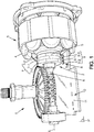
- the subject of the invention is a brushless DC electric motor for a motor vehicle wiper system, referenced 1 in the figure 1 .
- the electric motor 1 comprises a rotor 2 and a stator 3.
- the stator 3 comprises a plurality of electromagnetic excitation coils 4 of the rotor 2.
- the rotor 2 comprises a multipole magnet 5 mounted to be driven in a rotational movement about an axis of rotation.
- the axis of rotation is called later longitudinal axis, and referenced L.
- the electric motor 1 is configured so that the rotor 2 rotates in the stator 3, which causes a rotation of a motor shaft 6 integral with the multipole magnet 5.
- the driving shaft 6 extends along the longitudinal axis L.
- the multipole magnet 5 is provided with at least three multipolar axial layers 7.
- the multipole magnet 5 comprises three multipole axial layers 7, referenced 7-1, 7-2 and 7-3.
- each multipole axial layer 7 is in the form of a ring.
- the layers 7 are called "axial" layers because the rings are arranged one after the other along the longitudinal axis L.
- the rings 7 are contiguous to each other along the longitudinal axis L.
- the rings 7 are parts of the same monobloc element.
- the multipolar axial layers 7 follow one another along the longitudinal axis L.
- the central multipolar axial layer is referenced 7-1 while two extreme multipole layers are referenced 7-2 and 7-3.
- the two extreme multipolar layers 7-2 and 7-3 are arranged on either side of the central multipole axial layer 7-1.
- the juxtaposition of the rings 7 reduces the size of the electric motor 1.
- the motor shaft 6 passes through the crowns 7 in their center.
- Each multipolar axial layer 7 is configured to rotate about the longitudinal axis L.
- the three position sensors 9 are distributed so as to determine the six switching times of the electromagnetic excitation coils of the stator by 360 ° rotation.
- the six switching steps correspond to a rotation of 360 ° electrical, that is to say a complete rotation of 360 ° of the rotor in the case where the permanent magnet comprises a single pair of poles.
- the six switching steps, corresponding to 360 ° electrical correspond to a rotation of 180 ° of the rotor and in the case of a magnet comprising three pairs of poles, the six switching steps, corresponding to 360 ° electrical, correspond to a rotation of 120 ° of the rotor. Switching from one switching to another is therefore performed at each rotation of an electrical angle of 60 ° of the drive shaft 6.
- the multipolar axial layers 7 are furthermore arranged in such a way that there is an angular offset between the poles of the same type (north and south) on at least two successive multipole axial layers 7, preferably on the three multipolar axial layers. successive.
- This angular offset between the magnets of two or three successive multipolar axial layers is a function of the number of pairs of poles of the multipole axial layers 7, and also a function of the distance y referenced in FIG. figure 2 and described below.
- each axial layer 7 comprises six poles.
- the configurations with two or four poles as those described above, are quite possible, as well as configurations with more than three pairs of poles.
- the electric motor 1 comprises also a device for determining the position of the rotor, referenced 8.
- the device for determining the position of the rotor 8 comprises a plurality of position sensors 9 of one of the multipole axial layers 7, each position sensor 9 being respectively associated with one of the multipole axial layers 7.
- each position sensor 9 is a Hall effect sensor.
- a Hall effect sensor referenced 9-1 is associated with the central multipole axial layer 7-1
- a Hall effect sensor referenced 9-2 is associated with the extreme multipole axial layer 7-2
- a sensor Hall effect referenced 9-3 is associated with the extreme multipole axial layer 7-3.
- the Hall effect sensors 9 are installed in a plane P containing a direction parallel to the longitudinal axis L while being aligned.
- the electric motor 1 also comprises a printed circuit board 10.
- One of the faces 11 of the printed circuit board 10 contains the plane P.
- the face 11 is disposed facing the rotor 2.
- the Hall effect sensors 9 are arranged on the face 11 of the printed circuit board 10.
- Each Hall effect sensor 9 is mounted so as to detect the successive transitions of the opposite poles during the rotation of the rotor 2 in the stator 3.
- each ring 7 comprises a longitudinal wall 12 that a plane of symmetry orthogonal to the longitudinal axis L divides virtually into two similar regions.
- the plane of symmetry comprises a median line 14 along the longitudinal wall 12.
- the center line of the multipolar axial layer 7-1 is referenced 14-1
- the center line of the multipole axial layer 7-2 is referenced 14-2
- the center line of the multipolar axial layer 7-3 is referenced 14-3. .
- a center 15-1 of the Hall effect sensor 9-1 is arranged opposite the center line 14-1 of the multipolar axial layer 7-1.
- the central Hall effect sensor 9-1 is centered axially relative to the central multipolar axial layer 7-1.
- the end sensor 9-2 is axially off-center relative to the axial multipolar axial layer 7-2.
- a center 15-2 of the end sensor 9-2 is offset with respect to the center line 14-2 of the multipolar axial layer 7-2.
- end sensor 9-3 is axially off-center relative to the extreme multipole axial layer 7-3.
- a center 15-3 of the end sensor 9-3 is shifted relative to the center line 14-3 of the multipolar axial layer 7-3.
- This configuration makes it possible to reduce a thickness of the extreme multipole axial layers 7-2 and 7-3.
- the multipolar magnet requires less material and the electric motor 1 is short, which reduces the overall size of the electric motor 1.
- the distance d between the center 15-2 of the end sensor 9-2 and the center 15-1 of the central sensor 9-1 is greater than the distance D between the median line 14-2 of the axial layer multipolar 9-2 and the central line 14-1 of the central multipolar axial layer 7-1.
- the sensors 9-1 and 9-2 are farther apart than a centered position of the sensor 9-2 relative to the center line 14-2.
- This separation of the sensors 9-1 and 9-2 ensures that the end sensor 9-2 is not sensitive to the magnetic transitions of the central multipole axial layer 7-1 even in the case of a small thickness of the extreme multipolar axial layer 7. 2 and / or the central multipolar axial layer 7-1.
- the distance dd between the center 15-3 of the extremal sensor 9-3 and the center 15-1 of the central sensor 9-1 is greater than the distance DD between the median line 14-3 of the multipole axial extremal layer. 9-3 and the centerline 14-1 of the central multipolar axial layer 7-1.
- the sensors 9-1 and 9-3 are farther apart from one another than a centered position of the sensor 9-3 relative to the center line 14-3.
- This separation of the sensors 9-1 and 9-3 ensures that the extremal sensor 9-3 is not sensitive to the magnetic transitions of the central multipolar axial layer 7-1, even in the case of a small thickness of the extreme multipolar axial layer 7. 3 and / or the central multipolar axial layer 7-1.
- the central multipolar axial layer 7-1 has a thickness, noted E1, greater than the thicknesses of the axial multipole axial layers 7-2 and 7-3, denoted respectively E2 and E3.
- the two extreme layers 7-2, 7-3 are of different thicknesses.
- the multipole axial layers 7-1 to 7-3 are of identical thickness.
- the end sensor 9-2 is preferably disposed in a zone 16-2 off-center axially, that is to say relative to the center line 14-2.
- the zone 16-2 consists of two regions 17 and 18.
- the first region 17 is disposed from a position facing the centerline 14-2, excluding it, to the multipolar axial layer 7-1.
- the region 18 is disposed from the median line 14-2, excluding it, towards one end of the multipolar axial layer 7-2 opposite to the multipolar axial layer 7-1.
- the end sensor 9-2 is preferably disposed at a distance from the center 15-2 within a range of values:] 0.38%] E 2.
- the end sensor 9-2 is preferably disposed at a distance from the center 15-2 within a range of values:] 0.63%] E 2.
- the senor is arranged not facing the multipole axial layer 9-2 but instead is shifted outwardly of the multipole magnet 5.
- the thickness E2 of the extreme multipole axial layer 7-2 can be chosen particularly low.
- the thickness E1 of the central multipolar axial layer 7-1 can be chosen particularly low.
- the zone 16-3 consists of two regions 19 and 20.
- the first region 19 is disposed from the center line 14-3, excluding it, to the multipolar axial layer 7-1.
- the region 20 is disposed from a position facing the median line 14-3, excluding it, towards one end of the multipolar axial layer 7-3 opposite to the multipole axial layer 7-1 .
- the end sensor 9-3 is disposed at a distance from the center 15-3 within a range of values:] 0.38%] E 3.
- the end sensor 9-3 is disposed at a distance from the center 15-3 within a range of values:] 0.63%] E 3.
- the senor is arranged not facing the multipolar axial layer 9-3 but instead is shifted outwards of the multipole magnet 5.
- the thickness E3 is of the order of a few millimeters, preferably between 3 mm and 10 mm, advantageously 4 mm.
- the thickness E3 of the extreme multipole axial layer 7-3 can be chosen particularly low.
- the thickness E1 of the central multipolar axial layer 7-1 can be chosen particularly low.
- the configuration according to the present invention it is possible to reduce the size, in particular the thickness, of the multipolar axial layers of the multipolar magnet while monitoring the position of each of the layers.
- the end layers are advantageously of smaller thicknesses, which reduces the overall size of the electric motor.
Applications Claiming Priority (1)
| Application Number | Priority Date | Filing Date | Title |
|---|---|---|---|
| FR1658928A FR3056354B1 (fr) | 2016-09-22 | 2016-09-22 | Moteur electrique a courant continu sans balais pour systeme d'essuyage de vehicule automobile |
Publications (2)
| Publication Number | Publication Date |
|---|---|
| EP3300233A1 true EP3300233A1 (de) | 2018-03-28 |
| EP3300233B1 EP3300233B1 (de) | 2022-05-11 |
Family
ID=57485700
Family Applications (1)
| Application Number | Title | Priority Date | Filing Date |
|---|---|---|---|
| EP17182115.0A Active EP3300233B1 (de) | 2016-09-22 | 2017-07-19 | Gleichstrom-elektromotor ohne wischblätter für scheibenreinigungssystem eines kraftfahrzeugs |
Country Status (3)
| Country | Link |
|---|---|
| EP (1) | EP3300233B1 (de) |
| JP (1) | JP7039225B2 (de) |
| FR (1) | FR3056354B1 (de) |
Citations (6)
| Publication number | Priority date | Publication date | Assignee | Title |
|---|---|---|---|---|
| US4319188A (en) * | 1978-02-28 | 1982-03-09 | Nippon Electric Co., Ltd. | Magnetic rotary encoder for detection of incremental angular displacement |
| EP0212662A2 (de) * | 1985-08-27 | 1987-03-04 | Kabushiki Kaisha S.G. | Gerät zur absoluten Drehpositionserkennung |
| EP0474904A1 (de) * | 1990-09-12 | 1992-03-18 | Siemens Aktiengesellschaft | Kommutator-Getriebe-Antriebseinheit, insbesondere Fensterheberantrieb für ein Kraftfahrzeug, und Verfahren zu deren Herstellung |
| EP0723136A1 (de) * | 1995-01-20 | 1996-07-24 | MAX STEGMANN Gmbh ANTRIEBSTECHNIK - ELEKTRONIK | Messeinrichtung für einen Drehwinkel |
| DE29901686U1 (de) * | 1999-02-01 | 1999-04-08 | Bosch Gmbh Robert | Scheibenwischerantriebsanordnung |
| US20150002001A1 (en) * | 2012-02-01 | 2015-01-01 | Valeo Systèmes d'Essuyage | Arrangement for determining the angular position of a shaft of an electric motor, and windscreen wiper motor with an arrangement for determining the angular position |
Family Cites Families (4)
| Publication number | Priority date | Publication date | Assignee | Title |
|---|---|---|---|---|
| JPH0634390A (ja) * | 1992-07-15 | 1994-02-08 | Hitachi Ltd | 位置検出装置 |
| US6935193B2 (en) * | 1999-12-06 | 2005-08-30 | Robert Bosch Gmbh | Device for measuring the angle and/or the angular velocity of a rotatable body and/or the torque acting upon said body |
| EP1883787A4 (de) * | 2005-05-25 | 2013-12-18 | Continental Automotive Canada Inc | Doppelpolmagnetstruktur mit zwei um 90 grad phasenverschobenen magneten zur positionserfassung in einem stellglied |
| JP2008267868A (ja) * | 2007-04-17 | 2008-11-06 | Ntn Corp | 回転検出装置および回転検出装置付き軸受 |
-
2016
- 2016-09-22 FR FR1658928A patent/FR3056354B1/fr active Active
-
2017
- 2017-07-19 EP EP17182115.0A patent/EP3300233B1/de active Active
- 2017-09-21 JP JP2017181293A patent/JP7039225B2/ja active Active
Patent Citations (6)
| Publication number | Priority date | Publication date | Assignee | Title |
|---|---|---|---|---|
| US4319188A (en) * | 1978-02-28 | 1982-03-09 | Nippon Electric Co., Ltd. | Magnetic rotary encoder for detection of incremental angular displacement |
| EP0212662A2 (de) * | 1985-08-27 | 1987-03-04 | Kabushiki Kaisha S.G. | Gerät zur absoluten Drehpositionserkennung |
| EP0474904A1 (de) * | 1990-09-12 | 1992-03-18 | Siemens Aktiengesellschaft | Kommutator-Getriebe-Antriebseinheit, insbesondere Fensterheberantrieb für ein Kraftfahrzeug, und Verfahren zu deren Herstellung |
| EP0723136A1 (de) * | 1995-01-20 | 1996-07-24 | MAX STEGMANN Gmbh ANTRIEBSTECHNIK - ELEKTRONIK | Messeinrichtung für einen Drehwinkel |
| DE29901686U1 (de) * | 1999-02-01 | 1999-04-08 | Bosch Gmbh Robert | Scheibenwischerantriebsanordnung |
| US20150002001A1 (en) * | 2012-02-01 | 2015-01-01 | Valeo Systèmes d'Essuyage | Arrangement for determining the angular position of a shaft of an electric motor, and windscreen wiper motor with an arrangement for determining the angular position |
Also Published As
| Publication number | Publication date |
|---|---|
| EP3300233B1 (de) | 2022-05-11 |
| FR3056354B1 (fr) | 2018-09-07 |
| JP7039225B2 (ja) | 2022-03-22 |
| FR3056354A1 (fr) | 2018-03-23 |
| JP2018079917A (ja) | 2018-05-24 |
Similar Documents
| Publication | Publication Date | Title |
|---|---|---|
| EP0162780B1 (de) | Einrichtung zum Feststellen der Rotordrehstelle einer drehenden Maschine | |
| EP0514530B1 (de) | Magnetischer lage- und geschwindigkeitssensor mit hallsonde | |
| EP1808609A1 (de) | Magnetlageranordnung eines Rotors mit einem elektromagnetischen Axiallager | |
| EP1408603B1 (de) | Vorrichtung zur Steuerung eines elektronisch kommutierten Motors mittels eines Positionssignals | |
| FR2948451A1 (fr) | Procede et dispositif pour determiner la position de reglage d'un element deplacable d'un vehicule automobile | |
| EP2153076A1 (de) | Mit einer indexierung ausgestattete tragevorrichtung | |
| EP3542450A1 (de) | Getriebemotor, zugehöriges wischersystem und zugehöriges steuerungsverfahren | |
| WO2009103870A2 (fr) | Dispositif d'etancheite a codeur magnetique integre comprenant au moins une levre en contact radial frottant | |
| EP1857783B1 (de) | Kodierer für Positionsmelder mit stabilisierendem Effekt auf das Gegen-Null-Gehen der magnetischen Induktion | |
| FR3059852A1 (fr) | Machine electrique tournante integrant un capteur de position magnetique. | |
| EP0487405B1 (de) | Drehzahlmessaufnehmer und Wälzlager, ausgerüstet mit einem solchen Aufnehmer | |
| FR3056845A1 (fr) | Moteur electrique a courant continu sans balais pour systeme d'essuyage de vehicule automobile | |
| FR2844591A1 (fr) | Dispositif de determination du deplacement d'un arbre | |
| EP3300233B1 (de) | Gleichstrom-elektromotor ohne wischblätter für scheibenreinigungssystem eines kraftfahrzeugs | |
| FR2796679A1 (fr) | Palier a roulement instrumente | |
| EP1693677A1 (de) | Vorrichtung zur Erfassung von Parametern der Drehung von zwei Elementen | |
| EP3300232B1 (de) | Gleichstrom-elektromotor ohne wischblätter für scheibenreinigungssystem eines kraftfahrzeugs | |
| WO2004084402A1 (fr) | Dispositif de commutation, palier a roulement et moteur electrique utilisant un tel dispositif | |
| WO2020084260A1 (fr) | Machine electrique avec mesurement plus precise | |
| FR2838186A1 (fr) | Dispositif de capteur magnetique de position angulaire | |
| WO2019207240A1 (fr) | Stator d'une machine electrique tournante comprenant un aimant à volume optimise | |
| EP1780875A2 (de) | Elektrische Maschine mit Hallsonden | |
| FR3074979A1 (fr) | Moteur electrique a courant continu sans balais pour systeme d'essuyage de vehicule automobile | |
| FR2646028A1 (fr) | Moteur electrique a commutation electronique | |
| FR3106449A1 (fr) | Machine électrique à flux transverse à aimants permanents au stator |
Legal Events
| Date | Code | Title | Description |
|---|---|---|---|
| PUAI | Public reference made under article 153(3) epc to a published international application that has entered the european phase |
Free format text: ORIGINAL CODE: 0009012 |
|
| STAA | Information on the status of an ep patent application or granted ep patent |
Free format text: STATUS: REQUEST FOR EXAMINATION WAS MADE |
|
| 17P | Request for examination filed |
Effective date: 20170719 |
|
| AK | Designated contracting states |
Kind code of ref document: A1 Designated state(s): AL AT BE BG CH CY CZ DE DK EE ES FI FR GB GR HR HU IE IS IT LI LT LU LV MC MK MT NL NO PL PT RO RS SE SI SK SM TR |
|
| AX | Request for extension of the european patent |
Extension state: BA ME |
|
| STAA | Information on the status of an ep patent application or granted ep patent |
Free format text: STATUS: EXAMINATION IS IN PROGRESS |
|
| 17Q | First examination report despatched |
Effective date: 20190807 |
|
| STAA | Information on the status of an ep patent application or granted ep patent |
Free format text: STATUS: EXAMINATION IS IN PROGRESS |
|
| GRAP | Despatch of communication of intention to grant a patent |
Free format text: ORIGINAL CODE: EPIDOSNIGR1 |
|
| STAA | Information on the status of an ep patent application or granted ep patent |
Free format text: STATUS: GRANT OF PATENT IS INTENDED |
|
| RIC1 | Information provided on ipc code assigned before grant |
Ipc: G01R 15/20 20060101ALN20211207BHEP Ipc: B60S 1/08 20060101ALN20211207BHEP Ipc: H02K 11/215 20160101ALN20211207BHEP Ipc: H02K 29/08 20060101AFI20211207BHEP |
|
| INTG | Intention to grant announced |
Effective date: 20211223 |
|
| GRAS | Grant fee paid |
Free format text: ORIGINAL CODE: EPIDOSNIGR3 |
|
| GRAA | (expected) grant |
Free format text: ORIGINAL CODE: 0009210 |
|
| STAA | Information on the status of an ep patent application or granted ep patent |
Free format text: STATUS: THE PATENT HAS BEEN GRANTED |
|
| AK | Designated contracting states |
Kind code of ref document: B1 Designated state(s): AL AT BE BG CH CY CZ DE DK EE ES FI FR GB GR HR HU IE IS IT LI LT LU LV MC MK MT NL NO PL PT RO RS SE SI SK SM TR |
|
| REG | Reference to a national code |
Ref country code: GB Ref legal event code: FG4D Free format text: NOT ENGLISH |
|
| REG | Reference to a national code |
Ref country code: CH Ref legal event code: EP |
|
| REG | Reference to a national code |
Ref country code: AT Ref legal event code: REF Ref document number: 1492326 Country of ref document: AT Kind code of ref document: T Effective date: 20220515 |
|
| REG | Reference to a national code |
Ref country code: DE Ref legal event code: R096 Ref document number: 602017057246 Country of ref document: DE |
|
| REG | Reference to a national code |
Ref country code: IE Ref legal event code: FG4D Free format text: LANGUAGE OF EP DOCUMENT: FRENCH |
|
| REG | Reference to a national code |
Ref country code: LT Ref legal event code: MG9D |
|
| REG | Reference to a national code |
Ref country code: NL Ref legal event code: MP Effective date: 20220511 |
|
| REG | Reference to a national code |
Ref country code: AT Ref legal event code: MK05 Ref document number: 1492326 Country of ref document: AT Kind code of ref document: T Effective date: 20220511 |
|
| PG25 | Lapsed in a contracting state [announced via postgrant information from national office to epo] |
Ref country code: SE Free format text: LAPSE BECAUSE OF FAILURE TO SUBMIT A TRANSLATION OF THE DESCRIPTION OR TO PAY THE FEE WITHIN THE PRESCRIBED TIME-LIMIT Effective date: 20220511 Ref country code: PT Free format text: LAPSE BECAUSE OF FAILURE TO SUBMIT A TRANSLATION OF THE DESCRIPTION OR TO PAY THE FEE WITHIN THE PRESCRIBED TIME-LIMIT Effective date: 20220912 Ref country code: NO Free format text: LAPSE BECAUSE OF FAILURE TO SUBMIT A TRANSLATION OF THE DESCRIPTION OR TO PAY THE FEE WITHIN THE PRESCRIBED TIME-LIMIT Effective date: 20220811 Ref country code: NL Free format text: LAPSE BECAUSE OF FAILURE TO SUBMIT A TRANSLATION OF THE DESCRIPTION OR TO PAY THE FEE WITHIN THE PRESCRIBED TIME-LIMIT Effective date: 20220511 Ref country code: LT Free format text: LAPSE BECAUSE OF FAILURE TO SUBMIT A TRANSLATION OF THE DESCRIPTION OR TO PAY THE FEE WITHIN THE PRESCRIBED TIME-LIMIT Effective date: 20220511 Ref country code: HR Free format text: LAPSE BECAUSE OF FAILURE TO SUBMIT A TRANSLATION OF THE DESCRIPTION OR TO PAY THE FEE WITHIN THE PRESCRIBED TIME-LIMIT Effective date: 20220511 Ref country code: GR Free format text: LAPSE BECAUSE OF FAILURE TO SUBMIT A TRANSLATION OF THE DESCRIPTION OR TO PAY THE FEE WITHIN THE PRESCRIBED TIME-LIMIT Effective date: 20220812 Ref country code: FI Free format text: LAPSE BECAUSE OF FAILURE TO SUBMIT A TRANSLATION OF THE DESCRIPTION OR TO PAY THE FEE WITHIN THE PRESCRIBED TIME-LIMIT Effective date: 20220511 Ref country code: ES Free format text: LAPSE BECAUSE OF FAILURE TO SUBMIT A TRANSLATION OF THE DESCRIPTION OR TO PAY THE FEE WITHIN THE PRESCRIBED TIME-LIMIT Effective date: 20220511 Ref country code: BG Free format text: LAPSE BECAUSE OF FAILURE TO SUBMIT A TRANSLATION OF THE DESCRIPTION OR TO PAY THE FEE WITHIN THE PRESCRIBED TIME-LIMIT Effective date: 20220811 Ref country code: AT Free format text: LAPSE BECAUSE OF FAILURE TO SUBMIT A TRANSLATION OF THE DESCRIPTION OR TO PAY THE FEE WITHIN THE PRESCRIBED TIME-LIMIT Effective date: 20220511 |
|
| PG25 | Lapsed in a contracting state [announced via postgrant information from national office to epo] |
Ref country code: RS Free format text: LAPSE BECAUSE OF FAILURE TO SUBMIT A TRANSLATION OF THE DESCRIPTION OR TO PAY THE FEE WITHIN THE PRESCRIBED TIME-LIMIT Effective date: 20220511 Ref country code: PL Free format text: LAPSE BECAUSE OF FAILURE TO SUBMIT A TRANSLATION OF THE DESCRIPTION OR TO PAY THE FEE WITHIN THE PRESCRIBED TIME-LIMIT Effective date: 20220511 Ref country code: LV Free format text: LAPSE BECAUSE OF FAILURE TO SUBMIT A TRANSLATION OF THE DESCRIPTION OR TO PAY THE FEE WITHIN THE PRESCRIBED TIME-LIMIT Effective date: 20220511 Ref country code: IS Free format text: LAPSE BECAUSE OF FAILURE TO SUBMIT A TRANSLATION OF THE DESCRIPTION OR TO PAY THE FEE WITHIN THE PRESCRIBED TIME-LIMIT Effective date: 20220911 |
|
| PG25 | Lapsed in a contracting state [announced via postgrant information from national office to epo] |
Ref country code: SM Free format text: LAPSE BECAUSE OF FAILURE TO SUBMIT A TRANSLATION OF THE DESCRIPTION OR TO PAY THE FEE WITHIN THE PRESCRIBED TIME-LIMIT Effective date: 20220511 Ref country code: SK Free format text: LAPSE BECAUSE OF FAILURE TO SUBMIT A TRANSLATION OF THE DESCRIPTION OR TO PAY THE FEE WITHIN THE PRESCRIBED TIME-LIMIT Effective date: 20220511 Ref country code: RO Free format text: LAPSE BECAUSE OF FAILURE TO SUBMIT A TRANSLATION OF THE DESCRIPTION OR TO PAY THE FEE WITHIN THE PRESCRIBED TIME-LIMIT Effective date: 20220511 Ref country code: EE Free format text: LAPSE BECAUSE OF FAILURE TO SUBMIT A TRANSLATION OF THE DESCRIPTION OR TO PAY THE FEE WITHIN THE PRESCRIBED TIME-LIMIT Effective date: 20220511 Ref country code: DK Free format text: LAPSE BECAUSE OF FAILURE TO SUBMIT A TRANSLATION OF THE DESCRIPTION OR TO PAY THE FEE WITHIN THE PRESCRIBED TIME-LIMIT Effective date: 20220511 Ref country code: CZ Free format text: LAPSE BECAUSE OF FAILURE TO SUBMIT A TRANSLATION OF THE DESCRIPTION OR TO PAY THE FEE WITHIN THE PRESCRIBED TIME-LIMIT Effective date: 20220511 |
|
| REG | Reference to a national code |
Ref country code: DE Ref legal event code: R097 Ref document number: 602017057246 Country of ref document: DE |
|
| PG25 | Lapsed in a contracting state [announced via postgrant information from national office to epo] |
Ref country code: MC Free format text: LAPSE BECAUSE OF FAILURE TO SUBMIT A TRANSLATION OF THE DESCRIPTION OR TO PAY THE FEE WITHIN THE PRESCRIBED TIME-LIMIT Effective date: 20220511 |
|
| REG | Reference to a national code |
Ref country code: CH Ref legal event code: PL |
|
| PLBE | No opposition filed within time limit |
Free format text: ORIGINAL CODE: 0009261 |
|
| STAA | Information on the status of an ep patent application or granted ep patent |
Free format text: STATUS: NO OPPOSITION FILED WITHIN TIME LIMIT |
|
| REG | Reference to a national code |
Ref country code: BE Ref legal event code: MM Effective date: 20220731 |
|
| PG25 | Lapsed in a contracting state [announced via postgrant information from national office to epo] |
Ref country code: AL Free format text: LAPSE BECAUSE OF FAILURE TO SUBMIT A TRANSLATION OF THE DESCRIPTION OR TO PAY THE FEE WITHIN THE PRESCRIBED TIME-LIMIT Effective date: 20220511 |
|
| 26N | No opposition filed |
Effective date: 20230214 |
|
| GBPC | Gb: european patent ceased through non-payment of renewal fee |
Effective date: 20220811 |
|
| PG25 | Lapsed in a contracting state [announced via postgrant information from national office to epo] |
Ref country code: LU Free format text: LAPSE BECAUSE OF NON-PAYMENT OF DUE FEES Effective date: 20220719 Ref country code: LI Free format text: LAPSE BECAUSE OF NON-PAYMENT OF DUE FEES Effective date: 20220731 Ref country code: CH Free format text: LAPSE BECAUSE OF NON-PAYMENT OF DUE FEES Effective date: 20220731 |
|
| PG25 | Lapsed in a contracting state [announced via postgrant information from national office to epo] |
Ref country code: SI Free format text: LAPSE BECAUSE OF FAILURE TO SUBMIT A TRANSLATION OF THE DESCRIPTION OR TO PAY THE FEE WITHIN THE PRESCRIBED TIME-LIMIT Effective date: 20220511 Ref country code: BE Free format text: LAPSE BECAUSE OF NON-PAYMENT OF DUE FEES Effective date: 20220731 |
|
| P01 | Opt-out of the competence of the unified patent court (upc) registered |
Effective date: 20230528 |
|
| PG25 | Lapsed in a contracting state [announced via postgrant information from national office to epo] |
Ref country code: IE Free format text: LAPSE BECAUSE OF NON-PAYMENT OF DUE FEES Effective date: 20220719 |
|
| PG25 | Lapsed in a contracting state [announced via postgrant information from national office to epo] |
Ref country code: GB Free format text: LAPSE BECAUSE OF NON-PAYMENT OF DUE FEES Effective date: 20220811 |
|
| PGFP | Annual fee paid to national office [announced via postgrant information from national office to epo] |
Ref country code: FR Payment date: 20230727 Year of fee payment: 7 Ref country code: DE Payment date: 20230712 Year of fee payment: 7 |
|
| PG25 | Lapsed in a contracting state [announced via postgrant information from national office to epo] |
Ref country code: IT Free format text: LAPSE BECAUSE OF FAILURE TO SUBMIT A TRANSLATION OF THE DESCRIPTION OR TO PAY THE FEE WITHIN THE PRESCRIBED TIME-LIMIT Effective date: 20220511 |
|
| PG25 | Lapsed in a contracting state [announced via postgrant information from national office to epo] |
Ref country code: HU Free format text: LAPSE BECAUSE OF FAILURE TO SUBMIT A TRANSLATION OF THE DESCRIPTION OR TO PAY THE FEE WITHIN THE PRESCRIBED TIME-LIMIT; INVALID AB INITIO Effective date: 20170719 |