EP3300201A1 - Procédé et dispositif destinés à la surveillance d'un dispositif de transmission d'énergie - Google Patents
Procédé et dispositif destinés à la surveillance d'un dispositif de transmission d'énergie Download PDFInfo
- Publication number
- EP3300201A1 EP3300201A1 EP16190346.3A EP16190346A EP3300201A1 EP 3300201 A1 EP3300201 A1 EP 3300201A1 EP 16190346 A EP16190346 A EP 16190346A EP 3300201 A1 EP3300201 A1 EP 3300201A1
- Authority
- EP
- European Patent Office
- Prior art keywords
- measured value
- frequency
- current
- frequency band
- monitoring
- Prior art date
- Legal status (The legal status is an assumption and is not a legal conclusion. Google has not performed a legal analysis and makes no representation as to the accuracy of the status listed.)
- Withdrawn
Links
Images

Classifications
-
- G—PHYSICS
- G01—MEASURING; TESTING
- G01R—MEASURING ELECTRIC VARIABLES; MEASURING MAGNETIC VARIABLES
- G01R31/00—Arrangements for testing electric properties; Arrangements for locating electric faults; Arrangements for electrical testing characterised by what is being tested not provided for elsewhere
- G01R31/50—Testing of electric apparatus, lines, cables or components for short-circuits, continuity, leakage current or incorrect line connections
-
- G—PHYSICS
- G01—MEASURING; TESTING
- G01R—MEASURING ELECTRIC VARIABLES; MEASURING MAGNETIC VARIABLES
- G01R31/00—Arrangements for testing electric properties; Arrangements for locating electric faults; Arrangements for electrical testing characterised by what is being tested not provided for elsewhere
- G01R31/08—Locating faults in cables, transmission lines, or networks
- G01R31/081—Locating faults in cables, transmission lines, or networks according to type of conductors
- G01R31/086—Locating faults in cables, transmission lines, or networks according to type of conductors in power transmission or distribution networks, i.e. with interconnected conductors
-
- G—PHYSICS
- G01—MEASURING; TESTING
- G01R—MEASURING ELECTRIC VARIABLES; MEASURING MAGNETIC VARIABLES
- G01R31/00—Arrangements for testing electric properties; Arrangements for locating electric faults; Arrangements for electrical testing characterised by what is being tested not provided for elsewhere
- G01R31/50—Testing of electric apparatus, lines, cables or components for short-circuits, continuity, leakage current or incorrect line connections
- G01R31/52—Testing for short-circuits, leakage current or ground faults
-
- G—PHYSICS
- G01—MEASURING; TESTING
- G01R—MEASURING ELECTRIC VARIABLES; MEASURING MAGNETIC VARIABLES
- G01R31/00—Arrangements for testing electric properties; Arrangements for locating electric faults; Arrangements for electrical testing characterised by what is being tested not provided for elsewhere
- G01R31/50—Testing of electric apparatus, lines, cables or components for short-circuits, continuity, leakage current or incorrect line connections
- G01R31/54—Testing for continuity
-
- H—ELECTRICITY
- H02—GENERATION; CONVERSION OR DISTRIBUTION OF ELECTRIC POWER
- H02H—EMERGENCY PROTECTIVE CIRCUIT ARRANGEMENTS
- H02H3/00—Emergency protective circuit arrangements for automatic disconnection directly responsive to an undesired change from normal electric working condition with or without subsequent reconnection ; integrated protection
- H02H3/16—Emergency protective circuit arrangements for automatic disconnection directly responsive to an undesired change from normal electric working condition with or without subsequent reconnection ; integrated protection responsive to fault current to earth, frame or mass
- H02H3/17—Emergency protective circuit arrangements for automatic disconnection directly responsive to an undesired change from normal electric working condition with or without subsequent reconnection ; integrated protection responsive to fault current to earth, frame or mass by means of an auxiliary voltage injected into the installation to be protected
-
- H—ELECTRICITY
- H02—GENERATION; CONVERSION OR DISTRIBUTION OF ELECTRIC POWER
- H02H—EMERGENCY PROTECTIVE CIRCUIT ARRANGEMENTS
- H02H5/00—Emergency protective circuit arrangements for automatic disconnection directly responsive to an undesired change from normal non-electric working conditions with or without subsequent reconnection
- H02H5/10—Emergency protective circuit arrangements for automatic disconnection directly responsive to an undesired change from normal non-electric working conditions with or without subsequent reconnection responsive to mechanical injury, e.g. rupture of line, breakage of earth connection
-
- H—ELECTRICITY
- H02—GENERATION; CONVERSION OR DISTRIBUTION OF ELECTRIC POWER
- H02H—EMERGENCY PROTECTIVE CIRCUIT ARRANGEMENTS
- H02H7/00—Emergency protective circuit arrangements specially adapted for specific types of electric machines or apparatus or for sectionalised protection of cable or line systems, and effecting automatic switching in the event of an undesired change from normal working conditions
- H02H7/26—Sectionalised protection of cable or line systems, e.g. for disconnecting a section on which a short-circuit, earth fault, or arc discharge has occured
- H02H7/261—Sectionalised protection of cable or line systems, e.g. for disconnecting a section on which a short-circuit, earth fault, or arc discharge has occured involving signal transmission between at least two stations
-
- H—ELECTRICITY
- H02—GENERATION; CONVERSION OR DISTRIBUTION OF ELECTRIC POWER
- H02J—CIRCUIT ARRANGEMENTS OR SYSTEMS FOR SUPPLYING OR DISTRIBUTING ELECTRIC POWER; SYSTEMS FOR STORING ELECTRIC ENERGY
- H02J50/00—Circuit arrangements or systems for wireless supply or distribution of electric power
- H02J50/10—Circuit arrangements or systems for wireless supply or distribution of electric power using inductive coupling
- H02J50/12—Circuit arrangements or systems for wireless supply or distribution of electric power using inductive coupling of the resonant type
-
- G—PHYSICS
- G01—MEASURING; TESTING
- G01R—MEASURING ELECTRIC VARIABLES; MEASURING MAGNETIC VARIABLES
- G01R31/00—Arrangements for testing electric properties; Arrangements for locating electric faults; Arrangements for electrical testing characterised by what is being tested not provided for elsewhere
- G01R31/08—Locating faults in cables, transmission lines, or networks
- G01R31/081—Locating faults in cables, transmission lines, or networks according to type of conductors
- G01R31/085—Locating faults in cables, transmission lines, or networks according to type of conductors in power transmission or distribution lines, e.g. overhead
Definitions
- the invention relates to a method for monitoring an energy transmission device, in particular a power transmission line or a power distribution network, via which or the electric power is transmitted at a predetermined network frequency.
- the invention has for its object to provide a method for monitoring an energy transmission device, which allows a reliable error detection, especially for those with a rigid neutral earthing.
- the invention provides that an electrical measurement signal with at least one non-network frequency, ie a frequency which differs from the mains frequency, or a non-network frequency band at a predetermined point of the energy transfer device is fed into this, at the predetermined location or another location of the energy transmission device is measured on the non-power frequency or the non-power frequency frequency band measured electrical quantity to form at least one measured value or frequency band-related Meßwertverlaufs and an error signal is generated if the measured value, the frequency band-related measurement, a with the measured value or The comparison value or comparison value course formed in the course of the measurement value indicates an error in the energy transmission device.
- a significant advantage of the method according to the invention is that even high-impedance errors with a rigid neutral point can be reliably detected by the inventively provided, targeted feeding of measurement signals with non-network frequency or with a non-mains frequency band, because high-impedance error at other frequencies as the network frequency - as inventors found - can make significantly more noticeable than at the mains frequency.
- the method can be carried out in a particularly simple and thus advantageous manner if the measured value or the frequency band-related measured value profile is detected while forming a reference value or reference profile at a time which is assumed to be free of errors.
- An error signal is preferably generated if the current measured value or the current frequency band-related measured value profile and / or a current comparison value or current comparison value profile formed with the current measured value or the current frequency band-related measured value profile deviates from the reference value or reference profile over a predetermined amount.
- an electrical voltage with non-mains frequency is fed and measured at the same place as the non-mains frequency measurement of the current in magnitude and / or phase.
- the measurement signal is fed to the energy transmission device at a predetermined point, referred to below as the first point, and the measured value or measured value profile is measured at another point, referred to below as the second point becomes.
- the line impedance, the line impedance characteristic, the characteristic impedance, the characteristic impedance curve in the frequency band, the attenuation of the energy transmission device or the attenuation curve of the energy transmission device in the frequency band can be advantageously formed.
- the current measured value or the current frequency band-related measured value profile as comparative value or comparative value profile
- the current line impedance, the current line impedance profile, the current one Characteristic impedance, the current characteristic impedance curve in the frequency band, the current attenuation of the energy transmission device and / or the attenuation curve of the energy transmission device in the frequency band is determined.
- the latter variant is particularly easy to carry out with regard to an evaluation in terms of characteristic impedance and / or damping, if the feeding and measuring takes place at different locations.
- the frequency of the voltage is traversed within a predetermined non-mainsfrequency frequency band and the current is measured in magnitude and / or phase for the frequency band.
- a first and a second monitoring device are in a communication connection, in particular based on transmitted via the energy transmission means non-network frequency communication signals or the measurement signals themselves (if they are also used as communication signals).
- the feeding of the measuring signal and the detection of the measured value or measured value course is preferably synchronized via the communication connection.
- the measured value, measured value profile, comparison value or comparative value profile is transmitted from the second monitoring device to the first monitoring device, in particular via the energy transmission device by means of a non-mains frequency communication signal, and the first monitoring device generates the error signal if the measured value, measured value course current Comparison value or current comparison value history indicates an error in the energy transmission device.
- the power transmission device at different locations two or more monitoring devices are connected, with each of which non-network frequency measurement signals are fed into the energy transmission device and / or non-network frequency measurements or measured value curves are detected and / or current comparison values or current comparison value curves are formed and / or monitoring device individually auxiliary error signals are generated.
- the measured values, the measured value profiles, the current comparison values, the current comparison value profiles and / or the auxiliary device error signals generated individually by the monitoring device are preferably transmitted to a central protection device.
- the central protection device preferably generates the error signal if one or more of the measured values or one or more of the measured value profiles or one or more of the current comparison values or one or more of the current comparative value profiles indicate an error in the energy transmission device.
- the non-power frequency of the electrical measurement signal or the non-power frequency band is preferably in a frequency range between 30 kHz and 30 MHz, in particular between 100 kHz and 500 kHz.
- the method preferably monitors a voltage network, in particular a medium-voltage network, with a rigid neutral point earthing.
- a medium-voltage network is understood here to mean a network with a mains voltage between 1 kV and 60 kV.
- the invention also relates to a monitoring device for monitoring an energy transmission device, in particular a power transmission line or a power distribution network, is transmitted via the electric power at a predetermined power frequency.
- the monitoring device has a measuring device which transmits to a non-network frequency or a non-network frequency band
- the measured electrical variable can be measured to form at least one measured value or frequency band-related measured value profile
- the monitoring device has an evaluation device which generates an error signal if the measured value, the frequency band-related measured value profile, a comparison value or comparison value profile formed with the measured value or the measured value profile point to an error in the Energy transmission device indicates.
- the monitoring device additionally has a measurement signal generation unit which can feed an electrical measurement signal with at least one non-network frequency, ie a frequency which differs from the network frequency, or a non-network frequency band at a predetermined point of the energy transmission device.
- a measurement signal generation unit which can feed an electrical measurement signal with at least one non-network frequency, ie a frequency which differs from the network frequency, or a non-network frequency band at a predetermined point of the energy transmission device.
- the monitoring device preferably also has a communication device which can transmit measured values, measured value profiles, current comparison values formed therewith, current comparison value profiles or auxiliary error signals generated monitoring device-individually to one or more other monitoring devices or a central protection device. It is also possible for the measurement signals to be generated in the form of communication signals, that is to say the measurement signals themselves form communication signals; In such a case, the measurement signal generation unit and the communication device may be constituted by one and the same unit.
- the invention further relates to a monitoring arrangement for monitoring a power transmission device, in particular a power transmission line or an energy distribution network over which electrical power is transmitted at a predetermined network frequency.
- the invention has at least one monitoring device as described above and at least one measuring signal generating unit which has an electrical measuring signal with at least one non-network frequency, ie a frequency which differs from the network frequency. or a non-power frequency band can feed into the energy transmission device.
- the measuring signal generating unit is preferably formed by a component of said monitoring device or a component of another monitoring device arranged at a different point of the energy transmission device.
- the monitoring arrangement has a central protection device with which the at least one monitoring device is connected and to which the measured values or measured value profiles, current comparison values formed therewith, current comparison value profiles or auxiliary error signals generated individually by the monitoring device are transmitted, and the central one Protective device is designed such that it generates the error signal when one or more of the measured values or one or more of the measured value curves or one or more of the current comparison values or one or more of the current comparison value curves indicate an error in the energy transfer device or receive a monitoring device individually generated auxiliary error signal becomes.
- the invention also relates to a power transmission device.
- At least one monitoring device as described above and / or a monitoring arrangement as described above are connected to the energy transmission device.
- the energy transmission device is preferably monitored by the monitoring device and / or the monitoring device according to a method as described above.
- the energy transfer device is preferably a medium-voltage network with a rigid star point grounding, a medium-voltage range of a power distribution network with a rigid star point grounding or a medium-voltage power transmission line with a rigid star point grounding.
- the FIG. 1 shows an embodiment of an energy distribution network 10, of which in the FIG. 1 a medium voltage range MV, a high voltage range HV and two low voltage ranges LV1 and LV2 are shown.
- the two low-voltage areas LV1 and LV2 are connected via a respective transformer 11 and 12 to the medium voltage range MV.
- the medium-voltage region MV is connected to the high-voltage region HV via a transformer 13 in connection.
- a first monitoring device 21 of a monitoring arrangement 20 having a plurality of monitoring devices 21 to 24 is connected to the medium-voltage region MV of the energy distribution network 10.
- a second monitoring device 22 is connected to the medium-voltage region MV of the energy distribution network 10 at a second location P2, and third and fourth monitoring devices 23 and 24 are connected to the medium-voltage region MV of the energy distribution network 10 at a third location P3 or at a fourth location P4 Connection.
- the first monitoring device 21 and the second monitoring device 22 include a power transmission line 14 of the medium voltage range MV between them;
- This energy transmission line 14 is equipped with a switch 30, which enables a shutdown of the power transmission line 14 and thus an electrical separation of the medium voltage range MV and the low voltage ranges LV1 and LV2 of the high voltage range HV.
- the first monitoring device 21 measures with one for reasons of clarity in FIG. 1 measuring device, also not shown, a related to the non-frequency frequency of the measurement signal S electrical measured variable M to form a measured value.
- the frequency of the measuring signal S is traversed by the measuring signal generating unit within a predetermined non-mainsfrequency frequency band; Such a passage through the frequency band makes it possible for the measuring device of the first monitoring device 21 to measure the electrical measured variable M to form a frequency band-related measured value profile.
- the first monitoring device 21 will evaluate the frequency band-related measured value profile and generate an error signal F if the frequency band-related measured value profile indicates an error in the energy distribution network 10, in particular the energy transmission line 14.
- the check of the frequency band-related measured value profile with a view to a possible error is preferably based on a reference curve RV (see. FIG. 2 performed by measuring the measured quantity M in the non-power frequency band at a time or in a time window, which is assumed to be error-free or was actually error-free.
- the impedance curve in the frequency band can be advantageously formed.
- the current impedance curve in the frequency band is preferably determined using the current frequency band-related measured value profile as the comparison value profile.
- FIG. 2 an embodiment for a reference curve RV over the frequency f is shown.
- the first monitoring device 21 will generate the error signal F, for example, if the current frequency band-related measured value profile or a comparison value profile formed therewith (eg the current characteristic impedance or attenuation profile) deviates from the reference profile RV beyond a predefined level.
- a tolerance band TB is shown, which represents a tolerable degree of deviations from the reference profile RV.
- the first monitoring device 21 can feed an electrical voltage at the first location P1 into the energy distribution network 10; It is - as explained above - preferably the frequency of the voltage within the in the FIG. 2 example shown non-power frequency bands between the lower frequency f1 and the upper frequency f2.
- the first monitoring device 21 can measure, for example, the current in terms of magnitude and / or phase for the non-mains frequency band and the currently measured current waveform in terms of magnitude and / or phase compare the previously determined reference curve RV - again in terms of magnitude and / or phase - for the current and / or determine with the current profile according to magnitude and / or phase (and the corresponding voltage curve) as a comparison value course an impedance curve, which is based on the comparison below.
- the comparison may be made using conventional mathematical techniques, such as cross-correlation functions, pattern recognition, (linear or non-linearly weighted) summation, or integration of deviation values over the trace, etc., and more particularly, neural network based the basis of a model-based (substitute model of the electric network) state estimation.
- the monitoring device 21 will assume that no error has occurred in the power distribution network 10 or on the energy transmission line 14 and waive the generation of an error signal F.
- the first monitoring device 21 detects that the current measured according to magnitude and / or phase or the current comparison value profile of the reference profile RV according to FIG. 2 Deviates beyond the tolerance band TB, so it will close an error and generate the error signal F.
- the error signal F can serve, for example, as a switching signal for the switch 30, which opens in the presence of the error signal F and separates the energy transmission line 14 from the high-voltage region HV or from the transformer 13.
- the monitoring devices 22, 23 and 24 connected at the points P2, P3 and P4 can be operated in an analogous manner or the same way as the first monitoring device 21. In other words, they can also be self-employed feed an electrical measurement signal S and measure an electrical parameter M and in response to the measured parameter M close to an error.
- the measuring signals S of the monitoring devices 21, 22, 23 and 24 connected at the points P1, P2, P3 and P4 preferably differ in the time-frequency range with a view to distinguishing the signals.
- Such a synchronization preferably takes place via communication signals KS, which are transmitted via a separate communication network or particularly preferably via the energy distribution network 10.
- communication signals KS can be made of known communication techniques, as they are known, for example, under the technical term power line carrier technology.
- Devices are connected, for example via the already mentioned communication signals KS.
- the monitoring devices 22 to 24 can transmit the measured values or measured value profiles, comparison values or comparison value profiles or possibly already generated monitoring device-specific auxiliary error signals to the first monitoring device 21 functioning as a central protection device, which subsequently evaluates the obtained measured value profiles or comparison value profiles and / or in case of reception
- a supervising device-individually generated auxiliary error signal generates a central error signal F for switching off the switch 30.
- the first monitoring device 21 can measure the measured variable M for the non-power frequency band and measure a frequency band-related measured value profile which relates to the measurement signal S of the second monitoring device 22. Subsequently, the first monitoring device 21, the frequency band-related measured value profile with a reference curve RV (see FIG. 2 ), which it has recorded in advance for a time assumed to be free of errors when the measuring signal S is fed in by the second monitoring device 22. If the first monitoring device 21 determines that the currently recorded Frequency band-related measured value course or the current comparison value over a predetermined amount deviates from the reference curve RV, it generates the error signal F, as already mentioned above in connection with the FIGS. 1 to 2 has been explained.
- the first monitoring device 21 can cooperate with the third monitoring device 23 and the fourth monitoring device 24 and record measured variables which relate to measuring signals which have been fed by the third and fourth monitoring devices 23 and 24, respectively.
- the first monitoring device 21 can be used to feed in the electrical measuring signal S, and the remaining monitoring devices 22 to 24 receive measured values or frequency band-related measured value profiles, as has been explained above.
- the monitoring devices 22 to 24 it is advantageous for the monitoring devices 22 to 24 to evaluate the measured values or measured value profiles themselves and to generate a monitoring device-specific auxiliary error signal if currently measured measured value profiles or current comparison value profiles formed therefrom deviate from stored reference profiles RV over a predefined level.
- the monitoring device individually generated auxiliary error signals are preferably transmitted to the acting as a central protection device first monitoring device 21, which can subsequently generate the central error signal F to turn off the switch 30.
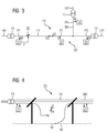
- the monitoring devices 23 and 24 can carry out measurements parallel to the first monitoring device and possibly a monitoring device-specific auxiliary error signal generate when the second monitoring device generates the measurement signal S (see FIG. 3 ). The same applies to feeding a measurement signal through the first, third or fourth monitoring device 21, 23 and 24, respectively.
- the frequency of the measuring signal S can be passed through the non-mains frequency band, so that the different frequencies are generated in succession.
- FIG. 4 shows by way of example a high-impedance fault at a fault location PF in the medium voltage range MV of the energy distribution network 10 according to FIGS FIGS. 1 and 3 closer in detail. It can be seen that a phase conductor 14a of the three-phase power transmission line 14 has cracked and made ground contact to the ground 40. If the medium-voltage region MV is a medium-voltage network with a rigid star point grounding, then such an error (cf., for example, the monitoring device 21 in FIG FIG. 4 ) generally high impedance and difficult to see. Due to the above related to the FIGS.
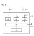
- FIG. 5 shows an embodiment of a monitoring device 100, as one of the monitoring devices 21 to 24 of the monitoring arrangement 20 according to the FIGS. 1 to 4 can be used.
- the monitoring device 100 has a measurement signal generating device 110 which has an electrical measurement signal S with at least one non-network frequency or a non-network frequency band at a predetermined location of an energy transmission device, for example the energy distribution network 10 or the energy transmission line 14 the FIGS. 1 to 4 can feed.
- an energy transmission device for example the energy distribution network 10 or the energy transmission line 14 the FIGS. 1 to 4 can feed.
- the monitoring device 100 has a measuring device 120, which can measure an electrical measured variable M while forming at least one measured value or frequency band-related measured value profile.
- an evaluation device 130 Connected to the measuring signal generating device 110 and the measuring device 120 is an evaluation device 130, which activates the measuring signal generating device and evaluates the measuring results of the measuring device 120, for example, by forming current comparison value profiles.
- a memory 140 is preferably connected, in which reference values or reference curves RV are stored, which have been measured at times that are assumed to be error-free. Based on reference values or reference curves, the evaluation device 130 can generate an error signal F (for example, if it works as a master device) or a monitoring device-specific auxiliary error signal Fi (for example, if it works as a slave device) when comparing current measured values or measured value curves or current comparison value values or current comparison value profiles with the stored reference values or stored reference curves on an error closes.
- F for example, if it works as a master device
- Fi for example, if it works as a slave device
- the monitoring device 100 also preferably has a communication device 150, which allows communication with other monitoring devices and / or a central protection device.
- the communication device 150 is preferably suitable for outputting measured values or measured value profiles and / or monitoring device-individually generated auxiliary error signals Fi by means of communication signals KS. If the monitoring device 100 operates as a central protection device, it preferably outputs error signals F at a separate error signal output A100.
- the measuring signal generating unit 110, the measuring device 120 and the evaluation device 130 may be formed by software modules of a data processing device, which preferably comprises one or more microprocessors.
Landscapes
- Physics & Mathematics (AREA)
- General Physics & Mathematics (AREA)
- Engineering & Computer Science (AREA)
- Power Engineering (AREA)
- Computer Networks & Wireless Communication (AREA)
- Remote Monitoring And Control Of Power-Distribution Networks (AREA)
- Locating Faults (AREA)
Priority Applications (5)
| Application Number | Priority Date | Filing Date | Title |
|---|---|---|---|
| EP16190346.3A EP3300201A1 (fr) | 2016-09-23 | 2016-09-23 | Procédé et dispositif destinés à la surveillance d'un dispositif de transmission d'énergie |
| CA2978932A CA2978932C (fr) | 2016-09-23 | 2017-09-12 | Methode et dispositif de surveillance d'un appareil de transmission d'energie |
| BR102017019836-7A BR102017019836B1 (pt) | 2016-09-23 | 2017-09-15 | Método para o monitoramento de um dispositivo de transmissão de energia, dispositivo e disposição de monitoramento, e, disposição de transmissão de energia |
| SA117380881A SA117380881B1 (ar) | 2016-09-23 | 2017-09-20 | طرق وجهاز لمراقبة جهاز نقل طاقة |
| US15/713,928 US10514414B2 (en) | 2016-09-23 | 2017-09-25 | Method and device for monitoring an energy transmission device |
Applications Claiming Priority (1)
| Application Number | Priority Date | Filing Date | Title |
|---|---|---|---|
| EP16190346.3A EP3300201A1 (fr) | 2016-09-23 | 2016-09-23 | Procédé et dispositif destinés à la surveillance d'un dispositif de transmission d'énergie |
Publications (1)
| Publication Number | Publication Date |
|---|---|
| EP3300201A1 true EP3300201A1 (fr) | 2018-03-28 |
Family
ID=56990335
Family Applications (1)
| Application Number | Title | Priority Date | Filing Date |
|---|---|---|---|
| EP16190346.3A Withdrawn EP3300201A1 (fr) | 2016-09-23 | 2016-09-23 | Procédé et dispositif destinés à la surveillance d'un dispositif de transmission d'énergie |
Country Status (4)
| Country | Link |
|---|---|
| US (1) | US10514414B2 (fr) |
| EP (1) | EP3300201A1 (fr) |
| CA (1) | CA2978932C (fr) |
| SA (1) | SA117380881B1 (fr) |
Cited By (1)
| Publication number | Priority date | Publication date | Assignee | Title |
|---|---|---|---|---|
| US10768243B2 (en) | 2017-10-27 | 2020-09-08 | Siemens Aktiengesellschaft | Method and detection device for detecting a high-impedance ground fault in an electrical energy supply network with a grounded neutral point |
Families Citing this family (1)
| Publication number | Priority date | Publication date | Assignee | Title |
|---|---|---|---|---|
| EP3557728A1 (fr) * | 2018-04-19 | 2019-10-23 | Siemens Aktiengesellschaft | Système de récupération de puissance dynamique |
Citations (5)
| Publication number | Priority date | Publication date | Assignee | Title |
|---|---|---|---|---|
| WO2003016850A2 (fr) * | 2001-08-15 | 2003-02-27 | Abb Inc. | Systeme et procede de localisation d'un defaut dans des reseaux de distribution d'energie non mis a la terre, et mis a la terre a forte impedance |
| WO2005050229A1 (fr) * | 2003-11-24 | 2005-06-02 | Dipl.-Ing. Walther Bender Gmbh & Co. Kg | Procede pour determiner la resistance d'isolement ohmique |
| EP1669767A1 (fr) * | 2004-12-10 | 2006-06-14 | General Electric Company | Système et procédé de localisation d'un défaut de mise à la terre dans un système de distribution d'énergie électrique |
| WO2015168260A1 (fr) * | 2014-04-29 | 2015-11-05 | The University Of Akron | Réseau de capteurs intelligents permettant de surveiller l'état d'un réseau électrique |
| US20160276820A1 (en) * | 2013-03-18 | 2016-09-22 | Win Ms | Device for protecting electrical networks |
Family Cites Families (1)
| Publication number | Priority date | Publication date | Assignee | Title |
|---|---|---|---|---|
| US6245065B1 (en) * | 1998-09-10 | 2001-06-12 | Scimed Life Systems, Inc. | Systems and methods for controlling power in an electrosurgical probe |
-
2016
- 2016-09-23 EP EP16190346.3A patent/EP3300201A1/fr not_active Withdrawn
-
2017
- 2017-09-12 CA CA2978932A patent/CA2978932C/fr active Active
- 2017-09-20 SA SA117380881A patent/SA117380881B1/ar unknown
- 2017-09-25 US US15/713,928 patent/US10514414B2/en active Active
Patent Citations (5)
| Publication number | Priority date | Publication date | Assignee | Title |
|---|---|---|---|---|
| WO2003016850A2 (fr) * | 2001-08-15 | 2003-02-27 | Abb Inc. | Systeme et procede de localisation d'un defaut dans des reseaux de distribution d'energie non mis a la terre, et mis a la terre a forte impedance |
| WO2005050229A1 (fr) * | 2003-11-24 | 2005-06-02 | Dipl.-Ing. Walther Bender Gmbh & Co. Kg | Procede pour determiner la resistance d'isolement ohmique |
| EP1669767A1 (fr) * | 2004-12-10 | 2006-06-14 | General Electric Company | Système et procédé de localisation d'un défaut de mise à la terre dans un système de distribution d'énergie électrique |
| US20160276820A1 (en) * | 2013-03-18 | 2016-09-22 | Win Ms | Device for protecting electrical networks |
| WO2015168260A1 (fr) * | 2014-04-29 | 2015-11-05 | The University Of Akron | Réseau de capteurs intelligents permettant de surveiller l'état d'un réseau électrique |
Cited By (1)
| Publication number | Priority date | Publication date | Assignee | Title |
|---|---|---|---|---|
| US10768243B2 (en) | 2017-10-27 | 2020-09-08 | Siemens Aktiengesellschaft | Method and detection device for detecting a high-impedance ground fault in an electrical energy supply network with a grounded neutral point |
Also Published As
| Publication number | Publication date |
|---|---|
| BR102017019836A8 (pt) | 2022-08-30 |
| CA2978932A1 (fr) | 2018-03-23 |
| CA2978932C (fr) | 2020-09-22 |
| SA117380881B1 (ar) | 2020-05-06 |
| BR102017019836A2 (pt) | 2018-05-02 |
| US20180088167A1 (en) | 2018-03-29 |
| US10514414B2 (en) | 2019-12-24 |
Similar Documents
| Publication | Publication Date | Title |
|---|---|---|
| DE102011076320B4 (de) | Erdungsüberwachungs-Vorrichtung und Ladesystem | |
| EP2996157B1 (fr) | Procédé de détection et dispositif de détection d'arcs électriques dans une installation photovoltaïque | |
| EP2585841B1 (fr) | Dispositif et procédé de surveillance d'une installation photovoltaïque | |
| EP2887081B1 (fr) | Dispositif destiné à la surveillance d'isolation | |
| EP1941285B1 (fr) | Procédé d'élaboration d'une série de données et appareil de terrain ainsi que système de détection de la qualité électro-énergétique d'un réseau d'alimentation en énergie | |
| EP3193420A1 (fr) | Procede, dispositif et systeme destines a localiser un defaut sur une ligne d'un reseau d'alimentation electrique | |
| EP2863553B1 (fr) | Dispositif de couplage pour coupler un dispositif de courant porteur en ligne et un dispositif de mesure à un réseau d'alimentation, et un noeud de mesure | |
| EP3968037B1 (fr) | Procédé et dispositif de détermination d'un emplacement défectueux dans un réseau de distribution d'énergie électrique | |
| DE102015214615A1 (de) | Verfahren und Vorrichtungen zur erweiterten Isolationsfehlersuche mit multifunktionalem Prüfstrom | |
| EP3069359B1 (fr) | Procédé et dispositif de surveillance de condensateurs de traversée pour réseau de courant alternatif triphasé | |
| EP3589964A1 (fr) | Procédé et dispositif pour surveiller les facteurs de pertes de traversées de condensateurs | |
| EP3658927A1 (fr) | Procédé et système permettant d'identifier des décharges partielles sur un équipement électrique | |
| WO1999056140A1 (fr) | Procede et dispositif pour la surveillance d'une ligne d'electrode d'une installation bipolaire de transport de courant continu a haute tension (c.c.h.t) | |
| EP2866041A1 (fr) | Noeuds de mesure, système et procédé de surveillance de l'état d'un réseau d'alimentation électrique | |
| EP2289137A1 (fr) | Ensemble et procédé pour produire un signal d erreur | |
| EP3300201A1 (fr) | Procédé et dispositif destinés à la surveillance d'un dispositif de transmission d'énergie | |
| EP3747098A1 (fr) | Dispositif de détection de défaut d'une station de réseau local et système d'annonce d'un défaut à un dispositif de commande central | |
| DE2604311A1 (de) | Phasenvergleichsrelais | |
| EP3819162B1 (fr) | Système d'alimentation électrique ferroviaire et procédé de surveillance de l'intégrité d'au moins un conducteur de raccordement de retour d'une connection de retour pour le courant de traction | |
| WO2009010084A1 (fr) | Concentrateur de données, système de protection redondant et procédé de surveillance d'un objet à protéger dans un réseau d'alimentation en énergie électrique | |
| EP3745146B1 (fr) | Procédé, dispositif et système de détermination d'une propriété d'une ligne de transmission d'énergie | |
| EP3042805B1 (fr) | Dispositif de surveillance d'un réseau de bord | |
| DE112019006585T5 (de) | Lichtbogen-erdungsfehler-detektionseinrichtung | |
| AT509241A1 (de) | Verfahren zum überprüfen der schalter bzw. der kabel einer überwachungseinrichtung des antriebs von schienenweichen sowie vorrichtung zur durchführung dieses verfahrens | |
| WO2009012800A1 (fr) | Appareil de protection et procédé de fonctionnement d'un appareil de protection |
Legal Events
| Date | Code | Title | Description |
|---|---|---|---|
| PUAI | Public reference made under article 153(3) epc to a published international application that has entered the european phase |
Free format text: ORIGINAL CODE: 0009012 |
|
| AK | Designated contracting states |
Kind code of ref document: A1 Designated state(s): AL AT BE BG CH CY CZ DE DK EE ES FI FR GB GR HR HU IE IS IT LI LT LU LV MC MK MT NL NO PL PT RO RS SE SI SK SM TR |
|
| AX | Request for extension of the european patent |
Extension state: BA ME |
|
| STAA | Information on the status of an ep patent application or granted ep patent |
Free format text: STATUS: THE APPLICATION IS DEEMED TO BE WITHDRAWN |
|
| 18D | Application deemed to be withdrawn |
Effective date: 20180929 |