EP3300201A1 - Method and device for monitoring an energy transmission device - Google Patents
Method and device for monitoring an energy transmission device Download PDFInfo
- Publication number
- EP3300201A1 EP3300201A1 EP16190346.3A EP16190346A EP3300201A1 EP 3300201 A1 EP3300201 A1 EP 3300201A1 EP 16190346 A EP16190346 A EP 16190346A EP 3300201 A1 EP3300201 A1 EP 3300201A1
- Authority
- EP
- European Patent Office
- Prior art keywords
- measured value
- frequency
- current
- frequency band
- monitoring
- Prior art date
- Legal status (The legal status is an assumption and is not a legal conclusion. Google has not performed a legal analysis and makes no representation as to the accuracy of the status listed.)
- Withdrawn
Links
Images

Classifications
-
- G—PHYSICS
- G01—MEASURING; TESTING
- G01R—MEASURING ELECTRIC VARIABLES; MEASURING MAGNETIC VARIABLES
- G01R31/00—Arrangements for testing electric properties; Arrangements for locating electric faults; Arrangements for electrical testing characterised by what is being tested not provided for elsewhere
- G01R31/50—Testing of electric apparatus, lines, cables or components for short-circuits, continuity, leakage current or incorrect line connections
-
- G—PHYSICS
- G01—MEASURING; TESTING
- G01R—MEASURING ELECTRIC VARIABLES; MEASURING MAGNETIC VARIABLES
- G01R31/00—Arrangements for testing electric properties; Arrangements for locating electric faults; Arrangements for electrical testing characterised by what is being tested not provided for elsewhere
- G01R31/08—Locating faults in cables, transmission lines, or networks
- G01R31/081—Locating faults in cables, transmission lines, or networks according to type of conductors
- G01R31/086—Locating faults in cables, transmission lines, or networks according to type of conductors in power transmission or distribution networks, i.e. with interconnected conductors
-
- G—PHYSICS
- G01—MEASURING; TESTING
- G01R—MEASURING ELECTRIC VARIABLES; MEASURING MAGNETIC VARIABLES
- G01R31/00—Arrangements for testing electric properties; Arrangements for locating electric faults; Arrangements for electrical testing characterised by what is being tested not provided for elsewhere
- G01R31/50—Testing of electric apparatus, lines, cables or components for short-circuits, continuity, leakage current or incorrect line connections
- G01R31/52—Testing for short-circuits, leakage current or ground faults
-
- G—PHYSICS
- G01—MEASURING; TESTING
- G01R—MEASURING ELECTRIC VARIABLES; MEASURING MAGNETIC VARIABLES
- G01R31/00—Arrangements for testing electric properties; Arrangements for locating electric faults; Arrangements for electrical testing characterised by what is being tested not provided for elsewhere
- G01R31/50—Testing of electric apparatus, lines, cables or components for short-circuits, continuity, leakage current or incorrect line connections
- G01R31/54—Testing for continuity
-
- H—ELECTRICITY
- H02—GENERATION; CONVERSION OR DISTRIBUTION OF ELECTRIC POWER
- H02H—EMERGENCY PROTECTIVE CIRCUIT ARRANGEMENTS
- H02H3/00—Emergency protective circuit arrangements for automatic disconnection directly responsive to an undesired change from normal electric working condition with or without subsequent reconnection ; integrated protection
- H02H3/16—Emergency protective circuit arrangements for automatic disconnection directly responsive to an undesired change from normal electric working condition with or without subsequent reconnection ; integrated protection responsive to fault current to earth, frame or mass
- H02H3/17—Emergency protective circuit arrangements for automatic disconnection directly responsive to an undesired change from normal electric working condition with or without subsequent reconnection ; integrated protection responsive to fault current to earth, frame or mass by means of an auxiliary voltage injected into the installation to be protected
-
- H—ELECTRICITY
- H02—GENERATION; CONVERSION OR DISTRIBUTION OF ELECTRIC POWER
- H02H—EMERGENCY PROTECTIVE CIRCUIT ARRANGEMENTS
- H02H5/00—Emergency protective circuit arrangements for automatic disconnection directly responsive to an undesired change from normal non-electric working conditions with or without subsequent reconnection
- H02H5/10—Emergency protective circuit arrangements for automatic disconnection directly responsive to an undesired change from normal non-electric working conditions with or without subsequent reconnection responsive to mechanical injury, e.g. rupture of line, breakage of earth connection
-
- H—ELECTRICITY
- H02—GENERATION; CONVERSION OR DISTRIBUTION OF ELECTRIC POWER
- H02H—EMERGENCY PROTECTIVE CIRCUIT ARRANGEMENTS
- H02H7/00—Emergency protective circuit arrangements specially adapted for specific types of electric machines or apparatus or for sectionalised protection of cable or line systems, and effecting automatic switching in the event of an undesired change from normal working conditions
- H02H7/26—Sectionalised protection of cable or line systems, e.g. for disconnecting a section on which a short-circuit, earth fault, or arc discharge has occured
- H02H7/261—Sectionalised protection of cable or line systems, e.g. for disconnecting a section on which a short-circuit, earth fault, or arc discharge has occured involving signal transmission between at least two stations
-
- H—ELECTRICITY
- H02—GENERATION; CONVERSION OR DISTRIBUTION OF ELECTRIC POWER
- H02J—CIRCUIT ARRANGEMENTS OR SYSTEMS FOR SUPPLYING OR DISTRIBUTING ELECTRIC POWER; SYSTEMS FOR STORING ELECTRIC ENERGY
- H02J50/00—Circuit arrangements or systems for wireless supply or distribution of electric power
- H02J50/10—Circuit arrangements or systems for wireless supply or distribution of electric power using inductive coupling
- H02J50/12—Circuit arrangements or systems for wireless supply or distribution of electric power using inductive coupling of the resonant type
-
- G—PHYSICS
- G01—MEASURING; TESTING
- G01R—MEASURING ELECTRIC VARIABLES; MEASURING MAGNETIC VARIABLES
- G01R31/00—Arrangements for testing electric properties; Arrangements for locating electric faults; Arrangements for electrical testing characterised by what is being tested not provided for elsewhere
- G01R31/08—Locating faults in cables, transmission lines, or networks
- G01R31/081—Locating faults in cables, transmission lines, or networks according to type of conductors
- G01R31/085—Locating faults in cables, transmission lines, or networks according to type of conductors in power transmission or distribution lines, e.g. overhead
Definitions
- the invention relates to a method for monitoring an energy transmission device, in particular a power transmission line or a power distribution network, via which or the electric power is transmitted at a predetermined network frequency.
- the invention has for its object to provide a method for monitoring an energy transmission device, which allows a reliable error detection, especially for those with a rigid neutral earthing.
- the invention provides that an electrical measurement signal with at least one non-network frequency, ie a frequency which differs from the mains frequency, or a non-network frequency band at a predetermined point of the energy transfer device is fed into this, at the predetermined location or another location of the energy transmission device is measured on the non-power frequency or the non-power frequency frequency band measured electrical quantity to form at least one measured value or frequency band-related Meßwertverlaufs and an error signal is generated if the measured value, the frequency band-related measurement, a with the measured value or The comparison value or comparison value course formed in the course of the measurement value indicates an error in the energy transmission device.
- a significant advantage of the method according to the invention is that even high-impedance errors with a rigid neutral point can be reliably detected by the inventively provided, targeted feeding of measurement signals with non-network frequency or with a non-mains frequency band, because high-impedance error at other frequencies as the network frequency - as inventors found - can make significantly more noticeable than at the mains frequency.
- the method can be carried out in a particularly simple and thus advantageous manner if the measured value or the frequency band-related measured value profile is detected while forming a reference value or reference profile at a time which is assumed to be free of errors.
- An error signal is preferably generated if the current measured value or the current frequency band-related measured value profile and / or a current comparison value or current comparison value profile formed with the current measured value or the current frequency band-related measured value profile deviates from the reference value or reference profile over a predetermined amount.
- an electrical voltage with non-mains frequency is fed and measured at the same place as the non-mains frequency measurement of the current in magnitude and / or phase.
- the measurement signal is fed to the energy transmission device at a predetermined point, referred to below as the first point, and the measured value or measured value profile is measured at another point, referred to below as the second point becomes.
- the line impedance, the line impedance characteristic, the characteristic impedance, the characteristic impedance curve in the frequency band, the attenuation of the energy transmission device or the attenuation curve of the energy transmission device in the frequency band can be advantageously formed.
- the current measured value or the current frequency band-related measured value profile as comparative value or comparative value profile
- the current line impedance, the current line impedance profile, the current one Characteristic impedance, the current characteristic impedance curve in the frequency band, the current attenuation of the energy transmission device and / or the attenuation curve of the energy transmission device in the frequency band is determined.
- the latter variant is particularly easy to carry out with regard to an evaluation in terms of characteristic impedance and / or damping, if the feeding and measuring takes place at different locations.
- the frequency of the voltage is traversed within a predetermined non-mainsfrequency frequency band and the current is measured in magnitude and / or phase for the frequency band.
- a first and a second monitoring device are in a communication connection, in particular based on transmitted via the energy transmission means non-network frequency communication signals or the measurement signals themselves (if they are also used as communication signals).
- the feeding of the measuring signal and the detection of the measured value or measured value course is preferably synchronized via the communication connection.
- the measured value, measured value profile, comparison value or comparative value profile is transmitted from the second monitoring device to the first monitoring device, in particular via the energy transmission device by means of a non-mains frequency communication signal, and the first monitoring device generates the error signal if the measured value, measured value course current Comparison value or current comparison value history indicates an error in the energy transmission device.
- the power transmission device at different locations two or more monitoring devices are connected, with each of which non-network frequency measurement signals are fed into the energy transmission device and / or non-network frequency measurements or measured value curves are detected and / or current comparison values or current comparison value curves are formed and / or monitoring device individually auxiliary error signals are generated.
- the measured values, the measured value profiles, the current comparison values, the current comparison value profiles and / or the auxiliary device error signals generated individually by the monitoring device are preferably transmitted to a central protection device.
- the central protection device preferably generates the error signal if one or more of the measured values or one or more of the measured value profiles or one or more of the current comparison values or one or more of the current comparative value profiles indicate an error in the energy transmission device.
- the non-power frequency of the electrical measurement signal or the non-power frequency band is preferably in a frequency range between 30 kHz and 30 MHz, in particular between 100 kHz and 500 kHz.
- the method preferably monitors a voltage network, in particular a medium-voltage network, with a rigid neutral point earthing.
- a medium-voltage network is understood here to mean a network with a mains voltage between 1 kV and 60 kV.
- the invention also relates to a monitoring device for monitoring an energy transmission device, in particular a power transmission line or a power distribution network, is transmitted via the electric power at a predetermined power frequency.
- the monitoring device has a measuring device which transmits to a non-network frequency or a non-network frequency band
- the measured electrical variable can be measured to form at least one measured value or frequency band-related measured value profile
- the monitoring device has an evaluation device which generates an error signal if the measured value, the frequency band-related measured value profile, a comparison value or comparison value profile formed with the measured value or the measured value profile point to an error in the Energy transmission device indicates.
- the monitoring device additionally has a measurement signal generation unit which can feed an electrical measurement signal with at least one non-network frequency, ie a frequency which differs from the network frequency, or a non-network frequency band at a predetermined point of the energy transmission device.
- a measurement signal generation unit which can feed an electrical measurement signal with at least one non-network frequency, ie a frequency which differs from the network frequency, or a non-network frequency band at a predetermined point of the energy transmission device.
- the monitoring device preferably also has a communication device which can transmit measured values, measured value profiles, current comparison values formed therewith, current comparison value profiles or auxiliary error signals generated monitoring device-individually to one or more other monitoring devices or a central protection device. It is also possible for the measurement signals to be generated in the form of communication signals, that is to say the measurement signals themselves form communication signals; In such a case, the measurement signal generation unit and the communication device may be constituted by one and the same unit.
- the invention further relates to a monitoring arrangement for monitoring a power transmission device, in particular a power transmission line or an energy distribution network over which electrical power is transmitted at a predetermined network frequency.
- the invention has at least one monitoring device as described above and at least one measuring signal generating unit which has an electrical measuring signal with at least one non-network frequency, ie a frequency which differs from the network frequency. or a non-power frequency band can feed into the energy transmission device.
- the measuring signal generating unit is preferably formed by a component of said monitoring device or a component of another monitoring device arranged at a different point of the energy transmission device.
- the monitoring arrangement has a central protection device with which the at least one monitoring device is connected and to which the measured values or measured value profiles, current comparison values formed therewith, current comparison value profiles or auxiliary error signals generated individually by the monitoring device are transmitted, and the central one Protective device is designed such that it generates the error signal when one or more of the measured values or one or more of the measured value curves or one or more of the current comparison values or one or more of the current comparison value curves indicate an error in the energy transfer device or receive a monitoring device individually generated auxiliary error signal becomes.
- the invention also relates to a power transmission device.
- At least one monitoring device as described above and / or a monitoring arrangement as described above are connected to the energy transmission device.
- the energy transmission device is preferably monitored by the monitoring device and / or the monitoring device according to a method as described above.
- the energy transfer device is preferably a medium-voltage network with a rigid star point grounding, a medium-voltage range of a power distribution network with a rigid star point grounding or a medium-voltage power transmission line with a rigid star point grounding.
- the FIG. 1 shows an embodiment of an energy distribution network 10, of which in the FIG. 1 a medium voltage range MV, a high voltage range HV and two low voltage ranges LV1 and LV2 are shown.
- the two low-voltage areas LV1 and LV2 are connected via a respective transformer 11 and 12 to the medium voltage range MV.
- the medium-voltage region MV is connected to the high-voltage region HV via a transformer 13 in connection.
- a first monitoring device 21 of a monitoring arrangement 20 having a plurality of monitoring devices 21 to 24 is connected to the medium-voltage region MV of the energy distribution network 10.
- a second monitoring device 22 is connected to the medium-voltage region MV of the energy distribution network 10 at a second location P2, and third and fourth monitoring devices 23 and 24 are connected to the medium-voltage region MV of the energy distribution network 10 at a third location P3 or at a fourth location P4 Connection.
- the first monitoring device 21 and the second monitoring device 22 include a power transmission line 14 of the medium voltage range MV between them;
- This energy transmission line 14 is equipped with a switch 30, which enables a shutdown of the power transmission line 14 and thus an electrical separation of the medium voltage range MV and the low voltage ranges LV1 and LV2 of the high voltage range HV.
- the first monitoring device 21 measures with one for reasons of clarity in FIG. 1 measuring device, also not shown, a related to the non-frequency frequency of the measurement signal S electrical measured variable M to form a measured value.
- the frequency of the measuring signal S is traversed by the measuring signal generating unit within a predetermined non-mainsfrequency frequency band; Such a passage through the frequency band makes it possible for the measuring device of the first monitoring device 21 to measure the electrical measured variable M to form a frequency band-related measured value profile.
- the first monitoring device 21 will evaluate the frequency band-related measured value profile and generate an error signal F if the frequency band-related measured value profile indicates an error in the energy distribution network 10, in particular the energy transmission line 14.
- the check of the frequency band-related measured value profile with a view to a possible error is preferably based on a reference curve RV (see. FIG. 2 performed by measuring the measured quantity M in the non-power frequency band at a time or in a time window, which is assumed to be error-free or was actually error-free.
- the impedance curve in the frequency band can be advantageously formed.
- the current impedance curve in the frequency band is preferably determined using the current frequency band-related measured value profile as the comparison value profile.
- FIG. 2 an embodiment for a reference curve RV over the frequency f is shown.
- the first monitoring device 21 will generate the error signal F, for example, if the current frequency band-related measured value profile or a comparison value profile formed therewith (eg the current characteristic impedance or attenuation profile) deviates from the reference profile RV beyond a predefined level.
- a tolerance band TB is shown, which represents a tolerable degree of deviations from the reference profile RV.
- the first monitoring device 21 can feed an electrical voltage at the first location P1 into the energy distribution network 10; It is - as explained above - preferably the frequency of the voltage within the in the FIG. 2 example shown non-power frequency bands between the lower frequency f1 and the upper frequency f2.
- the first monitoring device 21 can measure, for example, the current in terms of magnitude and / or phase for the non-mains frequency band and the currently measured current waveform in terms of magnitude and / or phase compare the previously determined reference curve RV - again in terms of magnitude and / or phase - for the current and / or determine with the current profile according to magnitude and / or phase (and the corresponding voltage curve) as a comparison value course an impedance curve, which is based on the comparison below.
- the comparison may be made using conventional mathematical techniques, such as cross-correlation functions, pattern recognition, (linear or non-linearly weighted) summation, or integration of deviation values over the trace, etc., and more particularly, neural network based the basis of a model-based (substitute model of the electric network) state estimation.
- the monitoring device 21 will assume that no error has occurred in the power distribution network 10 or on the energy transmission line 14 and waive the generation of an error signal F.
- the first monitoring device 21 detects that the current measured according to magnitude and / or phase or the current comparison value profile of the reference profile RV according to FIG. 2 Deviates beyond the tolerance band TB, so it will close an error and generate the error signal F.
- the error signal F can serve, for example, as a switching signal for the switch 30, which opens in the presence of the error signal F and separates the energy transmission line 14 from the high-voltage region HV or from the transformer 13.
- the monitoring devices 22, 23 and 24 connected at the points P2, P3 and P4 can be operated in an analogous manner or the same way as the first monitoring device 21. In other words, they can also be self-employed feed an electrical measurement signal S and measure an electrical parameter M and in response to the measured parameter M close to an error.
- the measuring signals S of the monitoring devices 21, 22, 23 and 24 connected at the points P1, P2, P3 and P4 preferably differ in the time-frequency range with a view to distinguishing the signals.
- Such a synchronization preferably takes place via communication signals KS, which are transmitted via a separate communication network or particularly preferably via the energy distribution network 10.
- communication signals KS can be made of known communication techniques, as they are known, for example, under the technical term power line carrier technology.
- Devices are connected, for example via the already mentioned communication signals KS.
- the monitoring devices 22 to 24 can transmit the measured values or measured value profiles, comparison values or comparison value profiles or possibly already generated monitoring device-specific auxiliary error signals to the first monitoring device 21 functioning as a central protection device, which subsequently evaluates the obtained measured value profiles or comparison value profiles and / or in case of reception
- a supervising device-individually generated auxiliary error signal generates a central error signal F for switching off the switch 30.
- the first monitoring device 21 can measure the measured variable M for the non-power frequency band and measure a frequency band-related measured value profile which relates to the measurement signal S of the second monitoring device 22. Subsequently, the first monitoring device 21, the frequency band-related measured value profile with a reference curve RV (see FIG. 2 ), which it has recorded in advance for a time assumed to be free of errors when the measuring signal S is fed in by the second monitoring device 22. If the first monitoring device 21 determines that the currently recorded Frequency band-related measured value course or the current comparison value over a predetermined amount deviates from the reference curve RV, it generates the error signal F, as already mentioned above in connection with the FIGS. 1 to 2 has been explained.
- the first monitoring device 21 can cooperate with the third monitoring device 23 and the fourth monitoring device 24 and record measured variables which relate to measuring signals which have been fed by the third and fourth monitoring devices 23 and 24, respectively.
- the first monitoring device 21 can be used to feed in the electrical measuring signal S, and the remaining monitoring devices 22 to 24 receive measured values or frequency band-related measured value profiles, as has been explained above.
- the monitoring devices 22 to 24 it is advantageous for the monitoring devices 22 to 24 to evaluate the measured values or measured value profiles themselves and to generate a monitoring device-specific auxiliary error signal if currently measured measured value profiles or current comparison value profiles formed therefrom deviate from stored reference profiles RV over a predefined level.
- the monitoring device individually generated auxiliary error signals are preferably transmitted to the acting as a central protection device first monitoring device 21, which can subsequently generate the central error signal F to turn off the switch 30.
- the monitoring devices 23 and 24 can carry out measurements parallel to the first monitoring device and possibly a monitoring device-specific auxiliary error signal generate when the second monitoring device generates the measurement signal S (see FIG. 3 ). The same applies to feeding a measurement signal through the first, third or fourth monitoring device 21, 23 and 24, respectively.
- the frequency of the measuring signal S can be passed through the non-mains frequency band, so that the different frequencies are generated in succession.
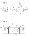
- FIG. 4 shows by way of example a high-impedance fault at a fault location PF in the medium voltage range MV of the energy distribution network 10 according to FIGS FIGS. 1 and 3 closer in detail. It can be seen that a phase conductor 14a of the three-phase power transmission line 14 has cracked and made ground contact to the ground 40. If the medium-voltage region MV is a medium-voltage network with a rigid star point grounding, then such an error (cf., for example, the monitoring device 21 in FIG FIG. 4 ) generally high impedance and difficult to see. Due to the above related to the FIGS.
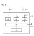
- FIG. 5 shows an embodiment of a monitoring device 100, as one of the monitoring devices 21 to 24 of the monitoring arrangement 20 according to the FIGS. 1 to 4 can be used.
- the monitoring device 100 has a measurement signal generating device 110 which has an electrical measurement signal S with at least one non-network frequency or a non-network frequency band at a predetermined location of an energy transmission device, for example the energy distribution network 10 or the energy transmission line 14 the FIGS. 1 to 4 can feed.
- an energy transmission device for example the energy distribution network 10 or the energy transmission line 14 the FIGS. 1 to 4 can feed.
- the monitoring device 100 has a measuring device 120, which can measure an electrical measured variable M while forming at least one measured value or frequency band-related measured value profile.
- an evaluation device 130 Connected to the measuring signal generating device 110 and the measuring device 120 is an evaluation device 130, which activates the measuring signal generating device and evaluates the measuring results of the measuring device 120, for example, by forming current comparison value profiles.
- a memory 140 is preferably connected, in which reference values or reference curves RV are stored, which have been measured at times that are assumed to be error-free. Based on reference values or reference curves, the evaluation device 130 can generate an error signal F (for example, if it works as a master device) or a monitoring device-specific auxiliary error signal Fi (for example, if it works as a slave device) when comparing current measured values or measured value curves or current comparison value values or current comparison value profiles with the stored reference values or stored reference curves on an error closes.
- F for example, if it works as a master device
- Fi for example, if it works as a slave device
- the monitoring device 100 also preferably has a communication device 150, which allows communication with other monitoring devices and / or a central protection device.
- the communication device 150 is preferably suitable for outputting measured values or measured value profiles and / or monitoring device-individually generated auxiliary error signals Fi by means of communication signals KS. If the monitoring device 100 operates as a central protection device, it preferably outputs error signals F at a separate error signal output A100.
- the measuring signal generating unit 110, the measuring device 120 and the evaluation device 130 may be formed by software modules of a data processing device, which preferably comprises one or more microprocessors.
Abstract
Die Erfindung bezieht sich u. a. auf ein Verfahren zum Überwachen einer Energieübertragungseinrichtung, insbesondere einer Energieübertragungsleitung (14) oder eines Energieverteilnetzes (10), über die oder das elektrischer Strom mit einer vorgegebenen Netzfrequenz übertragen wird. Erfindungsgemäß ist vorgesehen, dass ein elektrisches Messsignal (S) mit zumindest einer nicht-netzfrequenten Frequenz, also einer Frequenz, die sich von der Netzfrequenz unterscheidet, oder einem nicht-netzfrequenten Frequenzband an einer vorgegebenen Stelle (P1-P4) der Energieübertragungseinrichtung in diese eingespeist wird, an der vorgegebenen Stelle (P1-P4) oder einer anderen Stelle (P1-P4) der Energieübertragungseinrichtung eine auf die nicht-netzfrequente Frequenz oder das nicht-netzfrequente Frequenzband bezogene elektrische Messgröße (M) unter Bildung zumindest eines Messwerts oder frequenzbandbezogenen Messwertverlaufs gemessen wird und ein Fehlersignal (F) erzeugt wird, wenn der Messwert, der frequenzbandbezogene Messwertverlauf, ein mit dem Messwert oder dem Messwertverlauf gebildeter Vergleichswert oder Vergleichswertverlauf auf einen Fehler in der Energieübertragungseinrichtung hindeutet.The invention relates u. a. to a method for monitoring an energy transmission device, in particular a power transmission line (14) or an energy distribution network (10) over which or the electric power is transmitted at a predetermined network frequency. According to the invention, an electrical measurement signal (S) with at least one non-network frequency, ie a frequency which differs from the network frequency, or a non-network frequency band at a predetermined point (P1-P4) of the energy transmission device is fed into the latter is measured at the predetermined location (P1-P4) or another location (P1-P4) of the energy transmission device on the non-network frequency or the non-power frequency frequency band related electrical measurement (M) to form at least one measured value or frequency band-related measurement curve and an error signal (F) is generated when the measured value, the frequency band-related measured value profile, a comparison value or comparison value profile formed with the measured value or the measured value profile indicates an error in the energy transmission device.
Description
Die Erfindung bezieht sich auf ein Verfahren zum Überwachen einer Energieübertragungseinrichtung, insbesondere einer Energieübertragungsleitung oder eines Energieverteilnetzes, über die oder das elektrischer Strom mit einer vorgegebenen Netzfrequenz übertragen wird.The invention relates to a method for monitoring an energy transmission device, in particular a power transmission line or a power distribution network, via which or the electric power is transmitted at a predetermined network frequency.
Im Falle eines Leiterbruchs einer Energieübertragungsleitung oder eines Phasenleiters der Energieübertragungsleitung und im Falle eines nachfolgenden Herunterfallens eines Leitungsendes auf den Boden können, insbesondere bei hohem Erdwiderstand, sehr hochohmige Fehler auftreten. Insbesondere in Mittelspannungsnetzen mit starrer Sternpunkterdung stellen hochohmige Fehler ein großes Problem dar, weil diese Fehler schwer zu erkennen sind und die nach Fehlereintritt ggf. noch anliegende hohe Berührungsspannung Personen gefährden kann. In Nordamerika und in Teilen von Afrika, in denen starr geerdete Mittelspannungsnetze vorwiegend in Form von Freileitungen üblich sind, ereignen sich jährlich zahlreiche Unfälle mit Todesfolge durch solche hochohmigen Fehler.In the case of a conductor break of a power transmission line or a phase conductor of the power transmission line and in the case of a subsequent fall of a line end to the ground, especially at high earth resistance, very high-impedance errors can occur. High-impedance faults are a major problem, especially in medium-voltage networks with a rigid neutral earthing, because these faults are difficult to recognize and the high contact voltage which may still be present after the fault has occurred can endanger persons. In North America and parts of Africa where rigidly grounded medium-voltage grids are predominantly used in the form of overhead lines, numerous fatal accidents occur every year due to such high-impedance faults.
Die Erkennung der hochohmigen Fehler wird insbesondere durch folgende Faktoren erschwert:
- Die Fehlerströme sind in ihrer Höhe schwer von den Betriebsströmen/Lastströmen im fehlerfreien Fall zu unterscheiden.
- Durch die starre Sternpunkterdung des Einspeisetransformators in das Mittelspannungsnetz resultiert im einpoligen Fehlerfall keine Spannungsverlagerung, die durch ein Spannungsrelais, wie sie bei kompensierten Netzen in Europa im Einsatz sind, detektiert werden könnte.
- Im Betrieb werden die Netze im Allgemeinen unsymmetrisch belastet; folglich eignet sich der Reststrom über den Transformatorsternpunkt eines das Mittelspannungsnetz speisenden Transformators als Erkennungskriterium im Allgemeinen nicht.
- The fault currents are difficult to differentiate in height from the operating currents / load currents in the fault-free case.
- Due to the rigid star point earthing of the feed transformer in the medium-voltage network results in a single-pole fault, no voltage shift, which could be detected by a voltage relay, as they are in compensated networks in Europe, used.
- In operation, the networks are generally unbalanced; Consequently, the residual current through the transformer star point of a medium-voltage network is suitable feeding transformer as a recognition criterion in general not.
Der Erfindung liegt die Aufgabe zugrunde, ein Verfahren zum Überwachen einer Energieübertragungseinrichtung anzugeben, das eine zuverlässige Fehlererkennung ermöglicht, insbesondere für solche mit starrer Sternpunkterdung.The invention has for its object to provide a method for monitoring an energy transmission device, which allows a reliable error detection, especially for those with a rigid neutral earthing.
Diese Aufgabe wird erfindungsgemäß durch ein Verfahren mit den Merkmalen gemäß Patentanspruch 1 gelöst. Vorteilhafte Ausgestaltungen des erfindungsgemäßen Verfahrens sind in Unteransprüchen angegeben.This object is achieved by a method having the features according to claim 1. Advantageous embodiments of the method according to the invention are specified in subclaims.
Danach ist erfindungsgemäß vorgesehen, dass ein elektrisches Messsignal mit zumindest einer nicht-netzfrequenten Frequenz, also einer Frequenz, die sich von der Netzfrequenz unterscheidet, oder einem nicht-netzfrequenten Frequenzband an einer vorgegebenen Stelle der Energieübertragungseinrichtung in diese eingespeist wird, an der vorgegebenen Stelle oder einer anderen Stelle der Energieübertragungseinrichtung eine auf die nicht-netzfrequente Frequenz oder das nicht-netzfrequente Frequenzband bezogene elektrische Messgröße unter Bildung zumindest eines Messwerts oder frequenzbandbezogenen Messwertverlaufs gemessen wird und ein Fehlersignal erzeugt wird, wenn der Messwert, der frequenzbandbezogene Messwertverlauf, ein mit dem Messwert oder dem Messwertverlauf gebildeter Vergleichswert oder Vergleichswertverlauf auf einen Fehler in der Energieübertragungseinrichtung hindeutet.Thereafter, the invention provides that an electrical measurement signal with at least one non-network frequency, ie a frequency which differs from the mains frequency, or a non-network frequency band at a predetermined point of the energy transfer device is fed into this, at the predetermined location or another location of the energy transmission device is measured on the non-power frequency or the non-power frequency frequency band measured electrical quantity to form at least one measured value or frequency band-related Meßwertverlaufs and an error signal is generated if the measured value, the frequency band-related measurement, a with the measured value or The comparison value or comparison value course formed in the course of the measurement value indicates an error in the energy transmission device.
Ein wesentlicher Vorteil des erfindungsgemäßen Verfahrens besteht darin, dass durch das erfindungsgemäß vorgesehene, gezielte Einspeisen von Messsignalen mit nicht-netzfrequenter Frequenz bzw. mit einem nicht-netzfrequenten Frequenzband auch hochohmige Fehler mit starrer Sternpunkterdung sicher detektiert werden können, weil sich hochohmige Fehler bei anderen Frequenzen als der Netzfrequenz - wie erfinderseitig festgestellt wurde - signifikanter bemerkbar machen können als bei der Netzfrequenz.A significant advantage of the method according to the invention is that even high-impedance errors with a rigid neutral point can be reliably detected by the inventively provided, targeted feeding of measurement signals with non-network frequency or with a non-mains frequency band, because high-impedance error at other frequencies as the network frequency - as inventors found - can make significantly more noticeable than at the mains frequency.
Besonders einfach und damit vorteilhaft lässt sich das Verfahren durchführen, wenn der Messwert oder der frequenzbandbezogene Messwertverlauf unter Bildung eines Referenzwertes oder Referenzverlaufs zu einem Zeitpunkt erfasst wird, der als fehlerfrei angenommen wird. Ein Fehlersignal wird vorzugsweise erzeugt, wenn der aktuelle Messwert oder der aktuelle frequenzbandbezogene Messwertverlauf und/oder ein mit dem aktuellen Messwert oder dem aktuellen frequenzbandbezogenen Messwertverlauf gebildeter aktueller Vergleichswert oder aktueller Vergleichswertverlauf über ein vorgegebenes Maß vom Referenzwert oder Referenzverlauf abweicht.The method can be carried out in a particularly simple and thus advantageous manner if the measured value or the frequency band-related measured value profile is detected while forming a reference value or reference profile at a time which is assumed to be free of errors. An error signal is preferably generated if the current measured value or the current frequency band-related measured value profile and / or a current comparison value or current comparison value profile formed with the current measured value or the current frequency band-related measured value profile deviates from the reference value or reference profile over a predetermined amount.
Bei einer bevorzugten Ausführungsvariante ist vorgesehen, dass an der vorgegebenen Stelle als elektrisches Messsignal eine elektrische Spannung mit nicht-netzfrequenter Frequenz eingespeist wird und an derselben Stelle als die nicht-netzfrequente Messgröße der Strom nach Betrag und/oder Phase gemessen wird.In a preferred embodiment, it is provided that at the predetermined point as an electrical measurement signal, an electrical voltage with non-mains frequency is fed and measured at the same place as the non-mains frequency measurement of the current in magnitude and / or phase.
Alternativ oder zusätzlich kann im Rahmen einer weiteren vorteilhaften Ausgestaltung des Verfahrens vorgesehen sein, dass das Messsignal an einer vorgegebenen Stelle, nachfolgend erste Stelle genannt, der Energieübertragungseinrichtung eingespeist wird und an einer anderen Stelle, nachfolgend zweite Stelle genannt, der Energieübertragungseinrichtung der Messwert oder Messwertverlauf gemessen wird.Alternatively or additionally, it can be provided within the scope of a further advantageous embodiment of the method that the measurement signal is fed to the energy transmission device at a predetermined point, referred to below as the first point, and the measured value or measured value profile is measured at another point, referred to below as the second point becomes.
Als Referenzwert oder Referenzverlauf kann in vorteilhafter Weise die Leitungsimpedanz, der Leitungsimpedanzverlauf, der Wellenwiderstand, der Wellenwiderstandsverlauf in dem Frequenzband, die Dämpfung der Energieübertragungseinrichtung oder der Dämpfungsverlauf der Energieübertragungseinrichtung in dem Frequenzband gebildet werden. Bei dieser Ausgestaltung ist es vorteilhaft, wenn mit dem aktuellen Messwert oder dem aktuellen frequenzbandbezogenen Messwertverlauf (als Vergleichswert oder Vergleichswertverlauf) die aktuelle Leitungsimpedanz, der aktuelle Leitungsimpedanzverlauf, der aktuelle Wellenwiderstand, der aktuelle Wellenwiderstandsverlauf in dem Frequenzband, die aktuelle Dämpfung der Energieübertragungseinrichtung und/oder der Dämpfungsverlauf der Energieübertragungseinrichtung in dem Frequenzband ermittelt wird. Die letztgenannte Variante ist mit Blick auf eine Auswertung bezüglich Wellenwiderstand und/oder Dämpfung besonders einfach durchführbar, wenn das Einspeisen und Messen an unterschiedlichen Stellen erfolgt.As a reference value or reference curve, the line impedance, the line impedance characteristic, the characteristic impedance, the characteristic impedance curve in the frequency band, the attenuation of the energy transmission device or the attenuation curve of the energy transmission device in the frequency band can be advantageously formed. In this refinement, it is advantageous if, with the current measured value or the current frequency band-related measured value profile (as comparative value or comparative value profile), the current line impedance, the current line impedance profile, the current one Characteristic impedance, the current characteristic impedance curve in the frequency band, the current attenuation of the energy transmission device and / or the attenuation curve of the energy transmission device in the frequency band is determined. The latter variant is particularly easy to carry out with regard to an evaluation in terms of characteristic impedance and / or damping, if the feeding and measuring takes place at different locations.
Bezüglich der Auswertung der Messwerte wird es als vorteilhaft angesehen, wenn während der Messung die Frequenz der Spannung innerhalb eines vorgegebenen nicht-netzfrequenten Frequenzbands durchfahren wird und der Strom nach Betrag und/oder Phase für das Frequenzband gemessen wird.With regard to the evaluation of the measured values, it is considered advantageous if, during the measurement, the frequency of the voltage is traversed within a predetermined non-mainsfrequency frequency band and the current is measured in magnitude and / or phase for the frequency band.
Vorzugsweise stehen eine erste und eine zweite Überwachungseinrichtung in einer Kommunikationsverbindung, die insbesondere auf über die Energieübertragungseinrichtung übermittelten nicht-netzfrequenten Kommunikationssignalen oder den Messsignalen selbst (sofern sie zusätzlich als Kommunikationssignale verwendet werden) beruht. Das Einspeisen des Messsignals und das Erfassen des Messwerts oder Messwertverlaufs wird bevorzugt über die Kommunikationsverbindung synchronisiert.Preferably, a first and a second monitoring device are in a communication connection, in particular based on transmitted via the energy transmission means non-network frequency communication signals or the measurement signals themselves (if they are also used as communication signals). The feeding of the measuring signal and the detection of the measured value or measured value course is preferably synchronized via the communication connection.
Besonders vorteilhaft ist es, wenn der Messwert, Messwertverlauf, Vergleichswert oder Vergleichswertverlauf von der zweiten Überwachungseinrichtung zu der ersten Überwachungseinrichtung übertragen wird, insbesondere über die Energieübertragungseinrichtung mittels eines nicht-netzfrequenten Kommunikationssignals, und die erste Überwachungseinrichtung das Fehlersignal erzeugt, wenn der Messwert, Messwertverlauf aktuelle Vergleichswert oder aktuelle Vergleichswertverlauf auf einen Fehler in der Energieübertragungseinrichtung hindeutet.It is particularly advantageous if the measured value, measured value profile, comparison value or comparative value profile is transmitted from the second monitoring device to the first monitoring device, in particular via the energy transmission device by means of a non-mains frequency communication signal, and the first monitoring device generates the error signal if the measured value, measured value course current Comparison value or current comparison value history indicates an error in the energy transmission device.
Mit Blick auf eine besonders zuverlässige, insbesondere netzweite, Überwachung wird es als vorteilhaft angesehen, wenn an die Energieübertragungseinrichtung an verschiedenen Stellen zwei oder mehr Überwachungseinrichtungen angeschlossen sind, mit denen jeweils nicht-netzfrequente Messsignale in die Energieübertragungseinrichtung eingespeist und/oder nicht-netzfrequente Messwerte oder Messwertverläufe erfasst werden und/oder aktuelle Vergleichswerte oder aktuelle Vergleichswertverläufe gebildet werden und/oder überwachungseinrichtungsindividuell Hilfsfehlersignale erzeugt werden. Die Messwerte, die Messwertverläufe, die aktuellen Vergleichswerte, die aktuellen Vergleichswertverläufe und/oder die überwachungseinrichtungsindividuell erzeugten Hilfsfehlersignale werden bevorzugt zu einer zentralen Schutzeinrichtung übertragen. Die zentrale Schutzeinrichtung erzeugt vorzugsweise das Fehlersignal, wenn einer oder mehrere der Messwerte oder einer oder mehrere der Messwertverläufe oder einer oder mehrere der aktuellen Vergleichswerte oder einer oder mehrere der aktuellen Vergleichswertverläufe auf einen Fehler in der Energieübertragungseinrichtung hindeuten.With a view to a particularly reliable, in particular network-wide, monitoring, it is considered advantageous if to the power transmission device at different locations two or more monitoring devices are connected, with each of which non-network frequency measurement signals are fed into the energy transmission device and / or non-network frequency measurements or measured value curves are detected and / or current comparison values or current comparison value curves are formed and / or monitoring device individually auxiliary error signals are generated. The measured values, the measured value profiles, the current comparison values, the current comparison value profiles and / or the auxiliary device error signals generated individually by the monitoring device are preferably transmitted to a central protection device. The central protection device preferably generates the error signal if one or more of the measured values or one or more of the measured value profiles or one or more of the current comparison values or one or more of the current comparative value profiles indicate an error in the energy transmission device.
Die nicht-netzfrequente Frequenz des elektrischen Messsignals oder das nicht-netzfrequente Frequenzband liegt vorzugsweise in einem Frequenzbereich zwischen 30 kHz und 30 MHz, insbesondere zwischen 100 kHz und 500 kHz.The non-power frequency of the electrical measurement signal or the non-power frequency band is preferably in a frequency range between 30 kHz and 30 MHz, in particular between 100 kHz and 500 kHz.
Mit dem Verfahren wird vorzugsweise ein Spannungsnetz, insbesondere ein Mittelspannungsnetz, mit starrer Sternpunkterdung überwacht. Unter einem Mittelspannungsnetz wird hier ein Netz mit einer Netzspannung zwischen 1 kV und 60 kV verstanden.The method preferably monitors a voltage network, in particular a medium-voltage network, with a rigid neutral point earthing. A medium-voltage network is understood here to mean a network with a mains voltage between 1 kV and 60 kV.
Die Erfindung bezieht sich darüber hinaus auf eine Überwachungseinrichtung zum Überwachen einer Energieübertragungseinrichtung, insbesondere einer Energieübertragungsleitung oder eines Energieverteilnetzes, über die elektrischer Strom mit einer vorgegebenen Netzfrequenz übertragen wird.The invention also relates to a monitoring device for monitoring an energy transmission device, in particular a power transmission line or a power distribution network, is transmitted via the electric power at a predetermined power frequency.
Bezüglich einer solchen Überwachungseinrichtung ist erfindungsgemäß vorgesehen, dass die Überwachungseinrichtung eine Messeinrichtung aufweist, die eine auf eine nicht-netzfrequente Frequenz oder ein nicht-netzfrequentes Frequenzband bezogene elektrische Messgröße unter Bildung zumindest eines Messwerts oder frequenzbandbezogenen Messwertverlaufs messen kann, und die Überwachungseinrichtung eine Auswerteinrichtung aufweist, die ein Fehlersignal erzeugt, wenn der Messwert, der frequenzbandbezogene Messwertverlauf, ein mit dem Messwert oder dem Messwertverlauf gebildeter Vergleichswert oder Vergleichswertverlauf auf einen Fehler in der Energieübertragungseinrichtung hindeutet.With regard to such a monitoring device, it is provided according to the invention that the monitoring device has a measuring device which transmits to a non-network frequency or a non-network frequency band The measured electrical variable can be measured to form at least one measured value or frequency band-related measured value profile, and the monitoring device has an evaluation device which generates an error signal if the measured value, the frequency band-related measured value profile, a comparison value or comparison value profile formed with the measured value or the measured value profile point to an error in the Energy transmission device indicates.
Bezüglich der Vorteile der erfindungsgemäßen Überwachungseinrichtung sei auf die obigen Ausführungen im Zusammenhang mit dem erfindungsgemäßen Verfahren verwiesen.With regard to the advantages of the monitoring device according to the invention, reference is made to the above statements in connection with the method according to the invention.
Vorzugsweise weist die Überwachungseinrichtung zusätzlich eine Messsignalerzeugungseinheit auf, die ein elektrisches Messsignal mit zumindest einer nicht-netzfrequenten Frequenz, also einer Frequenz, die sich von der Netzfrequenz unterscheidet, oder einem nicht-netzfrequenten Frequenzband an einer vorgegebenen Stelle der Energieübertragungseinrichtung in diese einspeisen kann.Preferably, the monitoring device additionally has a measurement signal generation unit which can feed an electrical measurement signal with at least one non-network frequency, ie a frequency which differs from the network frequency, or a non-network frequency band at a predetermined point of the energy transmission device.
Vorzugsweise weist die Überwachungseinrichtung außerdem eine Kommunikationseinrichtung auf, die Messwerte, Messwertverläufe, mit diesen gebildete aktuelle Vergleichswerte, aktuelle Vergleichswertverläufe oder überwachungseinrichtungsindividuell erzeugte Hilfsfehlersignale an eine oder mehrere andere Überwachungseinrichtungen oder eine zentrale Schutzeinrichtung übermitteln kann. Auch ist es möglich, dass die Messsignale in Form von Kommunikationssignalen erzeugt werden, also die Messsignale selbst Kommunikationssignale bilden; in einem solchen Falle können die Messsignalerzeugungseinheit und die Kommunikationseinrichtung durch ein und dieselbe Einheit bzw. Einrichtung gebildet werden.The monitoring device preferably also has a communication device which can transmit measured values, measured value profiles, current comparison values formed therewith, current comparison value profiles or auxiliary error signals generated monitoring device-individually to one or more other monitoring devices or a central protection device. It is also possible for the measurement signals to be generated in the form of communication signals, that is to say the measurement signals themselves form communication signals; In such a case, the measurement signal generation unit and the communication device may be constituted by one and the same unit.
Die Erfindung bezieht sich darüber hinaus auf eine Überwachungsanordnung zum Überwachen einer Energieübertragungseinrichtung, insbesondere einer Energieübertragungsleitung oder eines Energieverteilnetzes, über die elektrischer Strom mit einer vorgegebenen Netzfrequenz übertragen wird.The invention further relates to a monitoring arrangement for monitoring a power transmission device, in particular a power transmission line or an energy distribution network over which electrical power is transmitted at a predetermined network frequency.
Bezüglich einer solchen Überwachungsanordnung ist erfindungsgemäß vorgesehen, dass diese zumindest eine Überwachungseinrichtung , wie sie oben beschrieben worden ist, und zumindest eine Messsignalerzeugungseinheit aufweist, die ein elektrisches Messsignal mit zumindest einer nicht-netzfrequenten Frequenz, also einer Frequenz, die sich von der Netzfrequenz unterscheidet, oder einem nicht-netzfrequenten Frequenzband in die Energieübertragungseinrichtung einspeisen kann.With regard to such a monitoring arrangement, it is provided according to the invention that it has at least one monitoring device as described above and at least one measuring signal generating unit which has an electrical measuring signal with at least one non-network frequency, ie a frequency which differs from the network frequency. or a non-power frequency band can feed into the energy transmission device.
Die Messsignalerzeugungseinheit wird vorzugsweise durch einen Bestandteil der genannten Überwachungseinrichtung oder einen Bestandteil einer anderen, an einer anderen Stelle der Energieübertragungseinrichtung angeordneten, Überwachungseinrichtung gebildet.The measuring signal generating unit is preferably formed by a component of said monitoring device or a component of another monitoring device arranged at a different point of the energy transmission device.
Als besonders vorteilhaft wird es angesehen, wenn die Überwachungsanordnung eine zentrale Schutzeinrichtung aufweist, mit der die zumindest eine Überwachungseinrichtung in Verbindung steht und zu der die Messwerte oder Messwertverläufe, mit diesen gebildete aktuelle Vergleichswerte, aktuelle Vergleichswertverläufe oder überwachungseinrichtungsindividuell erzeugte Hilfsfehlersignale übertragen werden, und die zentrale Schutzeinrichtung derart ausgestaltet ist, dass sie das Fehlersignal erzeugt, wenn einer oder mehrere der Messwerte oder einer oder mehrere der Messwertverläufe oder einer oder mehrere der aktuellen Vergleichswerte oder einer oder mehrere der aktuellen Vergleichswertverläufe auf einen Fehler in der Energieübertragungseinrichtung hindeuten oder ein überwachungseinrichtungsindividuell erzeugtes Hilfsfehlersignal empfangen wird.It is considered to be particularly advantageous if the monitoring arrangement has a central protection device with which the at least one monitoring device is connected and to which the measured values or measured value profiles, current comparison values formed therewith, current comparison value profiles or auxiliary error signals generated individually by the monitoring device are transmitted, and the central one Protective device is designed such that it generates the error signal when one or more of the measured values or one or more of the measured value curves or one or more of the current comparison values or one or more of the current comparison value curves indicate an error in the energy transfer device or receive a monitoring device individually generated auxiliary error signal becomes.
Die Erfindung bezieht sich außerdem auf eine Energieübertragungseinrichtung.The invention also relates to a power transmission device.
Erfindungsgemäß ist vorgesehen, dass an die Energieübertragungseinrichtung zumindest eine Überwachungseinrichtung wie oben beschrieben und/oder eine Überwachungsanordnung wie oben beschrieben angeschlossen ist. Die Energieübertragungseinrichtung wird mit der Überwachungseinrichtung und/oder der Überwachungsanordnung vorzugsweise nach einem Verfahren wie oben beschrieben überwacht.According to the invention, at least one monitoring device as described above and / or a monitoring arrangement as described above are connected to the energy transmission device. The energy transmission device is preferably monitored by the monitoring device and / or the monitoring device according to a method as described above.
Die Energieübertragungseinrichtung ist vorzugsweise ein Mittelspannungsnetz mit starrer Sternpunkterdung, ein Mittelspannungsbereich eines Energieverteilnetzes mit starrer Sternpunkterdung oder eine Mittelspannungsenergieübertragungsleitung mit starrer Sternpunkterdung.The energy transfer device is preferably a medium-voltage network with a rigid star point grounding, a medium-voltage range of a power distribution network with a rigid star point grounding or a medium-voltage power transmission line with a rigid star point grounding.
Die Erfindung wird nachfolgend anhand von Ausführungsbeispielen näher erläutert; dabei zeigen beispielhaft
- Figur 1
- ein Ausführungsbeispiel für eine erfindungsgemäße Überwachungsanordnung, anhand derer beispielhaft auch ein Ausführungsbeispiel für das erfindungsgemäße Verfahren erläutert wird,
- Figur 2
- einen Referenzverlauf, anhand dessen eine Prüfung vorgenommen werden kann, ob ein Fehler vorliegt und ein Fehlersignal zu erzeugen ist,
- Figur 3
- anhand der Überwachungsanordnung gemäß
Figur 1 eine andere Variante für einen Betrieb von Überwachungseinrichtungen der Überwachungsanordnung, - Figur 4
- einen Abschnitt einer Energieübertragungsleitung eines Energieverteilnetzes, das von der Überwachungsanordnung gemäß
Figur 1 überwacht wird, im Falle eines hochohmigen Fehlers einer Phasenleitung der Energieübertragungsleitung, und - Figur 5
- ein Ausführungsbeispiel für eine erfindungsgemäße Überwachungseinrichtung näher im Detail.
- FIG. 1
- An exemplary embodiment of a monitoring arrangement according to the invention, with reference to which an exemplary embodiment of the method according to the invention is explained by way of example,
- FIG. 2
- a reference curve, by means of which a check can be made as to whether an error exists and an error signal is to be generated,
- FIG. 3
- according to the surveillance arrangement according to
FIG. 1 another variant for operation of monitoring devices of the monitoring arrangement, - FIG. 4
- a portion of a power transmission line of a power distribution network, the of the monitoring arrangement according to
FIG. 1 is monitored, in the case of a high-impedance fault of a phase line of the power transmission line, and - FIG. 5
- An embodiment of a monitoring device according to the invention in more detail.
In den Figuren werden der Übersicht halber für identische oder vergleichbare Komponenten stets dieselben Bezugszeichen verwendet.For the sake of clarity, the same reference numbers are always used in the figures for identical or comparable components.
Die
Die beiden Niederspannungsbereiche LV1 und LV2 sind über jeweils einen Transformator 11 bzw. 12 an den Mittelspannungsbereich MV angeschlossen. Der Mittelspannungsbereich MV steht mit dem Hochspannungsbereich HV über einen Transformator 13 in Verbindung.The two low-voltage areas LV1 and LV2 are connected via a
An einer ersten Stelle P1 ist eine erste Überwachungseinrichtung 21 einer mehrere Überwachungseinrichtungen 21 bis 24 aufweisenden Überwachungsanordnung 20 an den Mittelspannungsbereich MV des Energieverteilnetzes 10 angeschlossen. Eine zweite Überwachungseinrichtung 22 ist an einer zweiten Stelle P2 mit dem Mittelspannungsbereich MV des Energieverteilnetzes 10 verbunden, und eine dritte und eine vierte Überwachungseinrichtung 23 und 24 stehen an einer dritten Stelle P3 bzw. an einer vierten Stelle P4 mit dem Mittelspannungsbereich MV des Energieverteilnetzes 10 in Verbindung.At a first location P1, a
Die erste Überwachungseinrichtung 21 und die zweite Überwachungseinrichtung 22 schließen eine Energieübertragungsleitung 14 des Mittelspannungsbereichs MV zwischen sich ein; diese Energieübertragungsleitung 14 ist mit einem Schalter 30 ausgestattet, der ein Abschalten der Energieübertragungsleitung 14 und damit ein elektrisches Abtrennen des Mittelspannungsbereichs MV sowie der Niederspannungsbereiche LV1 und LV2 von dem Hochspannungsbereich HV ermöglicht.The
Die Überwachungsanordnung 20 kann zum Schutz des Energieverteilnetzes 10, insbesondere des Mittelspannungsbereichs MV des Energieverteilnetzes 10, beispielsweise wie folgt betrieben werden:
Die erste Überwachungseinrichtung 21 speist mittels einer in derFigur 1 aus Gründen der Übersicht nicht weiter dargestellten Messsignalerzeugungseinheit ein elektrisches Messsignal S mit einer nicht-netzfrequenten Frequenz, also einer Frequenz, die sich von der Netzfrequenz des Energieverteilnetzes 10, insbesondere des Mittelspannungsbereichs MV, unterscheidet, an der ersten Stelle P1 indas Energieverteilnetz 10 ein.
- The
first monitoring device 21 feeds by means of a in theFIG. 1 For reasons of clarity not shown measurement signal generating unit, an electrical measurement signal S with a non-network frequency, ie a frequency that differs from the network frequency of theenergy distribution network 10, in particular the medium voltage range MV, at the first point P1 in the energy distribution network 10 a.
An der ersten Stelle P1 misst die erste Überwachungseinrichtung 21 mit einer aus Gründen der Übersicht in der
Besonders vorteilhaft ist es, wenn während der Messung durch die Messeinrichtung der Überwachungseinrichtung 21 die Frequenz des Messsignals S von der Messsignalerzeugungseinheit innerhalb eines vorgegebenen nicht-netzfrequenten Frequenzbands durchfahren wird; ein solches Durchfahren des Frequenzbands ermöglicht es der Messeinrichtung der ersten Überwachungseinrichtung 21, die elektrische Messgröße M unter Bildung eines frequenzbandbezogenen Messwertverlaufs zu messen.It is particularly advantageous if, during the measurement by the measuring device of the
Die erste Überwachungseinrichtung 21 wird den frequenzbandbezogenen Messwertverlauf auswerten und ein Fehlersignal F erzeugen, wenn der frequenzbandbezogene Messwertverlauf auf einen Fehler in dem Energieverteilnetz 10, insbesondere der Energieübertragungsleitung 14, hindeutet. Die Überprüfung des frequenzbandbezogenen Messwertverlaufs mit Blick auf einen etwaigen Fehler wird vorzugsweise anhand eines Referenzverlaufs RV (vgl.
Als Referenzverlauf RV kann in vorteilhafter Weise der Impedanzverlauf in dem Frequenzband gebildet werden. Bei dieser Ausgestaltung wird mit dem aktuellen frequenzbandbezogenen Messwertverlauf als Vergleichswertverlauf vorzugsweise der aktuelle Impedanzverlauf in dem Frequenzband ermittelt.As reference curve RV, the impedance curve in the frequency band can be advantageously formed. In this refinement, the current impedance curve in the frequency band is preferably determined using the current frequency band-related measured value profile as the comparison value profile.
In der
Die erste Überwachungseinrichtung 21 wird das Fehlersignal F beispielsweise erzeugen, wenn der aktuelle frequenzbandbezogene Messwertverlauf oder ein mit diesem gebildeter Vergleichswertverlauf (z. B. der aktuelle Wellenwiderstands- oder Dämpfungsverlauf) vom Referenzverlauf RV über ein vorgegebenes Maß hinaus abweicht. In der
Als elektrisches Messsignal S kann die erste Überwachungseinrichtung 21 eine elektrische Spannung an der ersten Stelle P1 in das Energieverteilnetz 10 einspeisen; dabei wird sie - wie oben erläutert - vorzugsweise die Frequenz der Spannung innerhalb des in der
Als Messgröße M kann die erste Überwachungseinrichtung 21 beispielsweise den Strom nach Betrag und/oder Phase für das nicht-netzfrequente Frequenzband messen und den jeweils aktuell gemessenen Stromverlauf nach Betrag und/oder Phase mit dem vorab ermittelten Referenzverlauf RV - wiederum nach Betrag und/oder Phase - für den Strom vergleichen und/oder mit dem Stromverlauf nach Betrag und/oder Phase (sowie dem korrespondierenden Spannungsverlauf) als Vergleichswertverlauf einen Impedanzverlauf ermitteln, der nachfolgend dem Vergleich zugrunde gelegt wird. Der Vergleich kann unter Heranziehung üblicher mathematischer Verfahren erfolgen, wie zum Beispiel auf der Basis von Kreuzkorrelationsfunktionen, von Mustererkennung, durch (linear oder nichtlinear gewichtete) Aufsummierung oder Integration von Abweichungswerten über dem Verlauf usw., und insbesondere auch auf der Basis von neuronalen Netzen auf der Basis einer modellgestützten (Ersatzmodell des elektrischen Netzes) Zustandsschätzung.As a measured variable M, the
Liegt der aktuell gemessene Stromverlauf nach Betrag und/oder Phase bzw. der aktuelle Vergleichswertverlauf innerhalb des Toleranzbands TB für den Referenzverlauf RV in
Stellt die erste Überwachungseinrichtung 21 hingegen fest, dass der aktuell gemessene Strom nach Betrag und/oder Phase bzw. der aktuelle Vergleichswertverlauf von dem Referenzverlauf RV gemäß
Das Fehlersignal F kann beispielsweise als Schaltsignal für den Schalter 30 dienen, der bei Vorliegen des Fehlersignals F öffnet und die Energieübertragungsleitung 14 vom Hochspannungsbereich HV bzw. vom Transformator 13 trennt.The error signal F can serve, for example, as a switching signal for the
Die an den Stellen P2, P3 und P4 angeschlossenen Überwachungseinrichtungen 22, 23 und 24 können in analoger Weise bzw. genauso wie die erste Überwachungseinrichtung 21 betrieben werden. Mit anderen Worten können sie auch selbständig ein elektrisches Messsignal S einspeisen und eine elektrische Messgröße M messen und in Abhängigkeit von der gemessenen Messgröße M auf einen Fehler schließen. Die Messsignale S der an den Stellen P1, P2, P3 und P4 angeschlossenen Überwachungseinrichtungen 21, 22, 23 und 24 unterscheiden sich mit Blick auf eine Unterscheidung der Signale vorzugsweise im Zeit-Frequenz-Bereich.The
Um zu vermeiden, dass die Überwachungseinrichtungen 21 bis 24 zu beliebigen Zeitpunkten elektrische Messsignale einspeisen und sich gegenseitig stören und es dadurch zu einer Verfälschung der Messergebnisse kommt, wird es als vorteilhaft angesehen, wenn sich die Überwachungseinrichtungen 21 bis 24 untereinander synchronisieren. Ein solches Synchronisieren erfolgt vorzugsweise über Kommunikationssignale KS, die über ein separates Kommunikationsnetz oder besonders bevorzugt über das Energieverteilnetz 10 übertragen werden. Bezüglich der Übertragung der Kommunikationssignale KS über das Energieverteilnetz 10 kann auf bekannte Kommunikationstechniken zurückgegriffen werden, wie sie beispielsweise unter dem Fachbegriff Power-Line-Carrier-Technologie bekannt sind.In order to avoid that the
Mit Blick auf den Betrieb der Überwachungsanordnung 20 wird es als besonders vorteilhaft angesehen, wenn eine der Überwachungseinrichtungen 21 bis 24, beispielsweise die erste Überwachungseinrichtung 21, als zentrale Schutzeinrichtung bzw. Master-Einrichtung fungiert, mit der die übrigen Überwachungseinrichtungen 22 bis 24 als Slave-Einrichtungen in Verbindung stehen, beispielsweise über die bereits erwähnten Kommunikationssignale KS. Mittels der Kommunikationssignale KS können die Überwachungseinrichtungen 22 bis 24 die von ihnen aufgenommenen Messwerte oder Messwertverläufe, Vergleichswerte oder Vergleichswertverläufe oder ggf. bereits überwachungseinrichtungsindividuell erzeugte Hilfsfehlersignale zu der als zentrale Schutzeinrichtung fungierenden ersten Überwachungseinrichtung 21 übertragen, die nachfolgend die Auswertung der erhaltenen Messwertverläufe oder Vergleichswertverläufe vornimmt und/oder im Falle eines Empfangs eines überwachungseinrichtungsindividuell erzeugten Hilfsfehlersignals ein zentrales Fehlersignal F zum Ausschalten des Schalters 30 erzeugt.With regard to the operation of the
Im Zusammenhang mit einem möglichen Betriebsverfahren der Überwachungsanordnung 20 gemäß
- Bei der Darstellung gemäß
Figur 3 wird beispielhaft davon ausgegangen, dass die zweite Überwachungseinrichtung 22 an der zweiten Stelle P2 ein Messsignal S indas Energieverteilnetz 10 bzw. dieEnergieübertragungsleitung 14 einspeist. Das Einspeisen des Messsignals S erfolgt vorzugsweise derart, dass die Frequenz des Messsignals S innerhalb eines vorgegebenen nicht-netzfrequenten Frequenzbands, beispielsweise dem Frequenzband zwischen der unteren Frequenz f1 und der oberen Frequenz f2 gemäßFigur 2 , durchfahren wird.
- In the presentation according to
FIG. 3 By way of example, it is assumed that thesecond monitoring device 22 feeds a measuring signal S into theenergy distribution network 10 or theenergy transmission line 14 at the second location P2. The feeding of the measuring signal S is preferably carried out such that the frequency of the measuring signal S within a predetermined non-mains frequency band, for example, the frequency band between the lower frequency f1 and the upper frequency f2 according toFIG. 2 , is passed through.
Synchronisiert zu dem Messsignal S - vorzugsweise durch ein Kommunikationssignal KS - kann die erste Überwachungseinrichtung 21 die Messgröße M für das nicht-netzfrequente Frequenzband messen und einen frequenzbandbezogenen Messwertverlauf messen, der sich auf das Messsignal S der zweiten Überwachungseinrichtung 22 bezieht. Nachfolgend kann die erste Überwachungseinrichtung 21 den frequenzbandbezogenen Messwertverlauf mit einem Referenzverlauf RV (siehe
In entsprechender Weise kann die erste Überwachungseinrichtung 21 mit der dritten Überwachungseinrichtung 23 und der vierten Überwachungseinrichtung 24 kooperieren und Messgrößen aufnehmen, die sich auf Messsignale beziehen, die von der dritten bzw. vierten Überwachungseinrichtung 23 bzw. 24 eingespeist worden sind.In a corresponding manner, the
Darüber hinaus ist es möglich, Einspeisestellen und Messstellen zu vertauschen. So kann beispielsweise die erste Überwachungseinrichtung 21 zum Einspeisen des elektrischen Messsignals S dienen, und die übrigen Überwachungseinrichtungen 22 bis 24 nehmen Messwerte oder frequenzbandbezogene Messwertverläufe auf, wie dies oben erläutert worden ist. Bei der letztgenannten Fallgestaltung ist es vorteilhaft, wenn die Überwachungseinrichtungen 22 bis 24 die Messwerte bzw. Messwertverläufe jeweils selbst auswerten und ein überwachungseinrichtungsindividuelles Hilfsfehlersignal erzeugen, wenn aktuell gemessene Messwertverläufe oder damit gebildete aktuelle Vergleichswertverläufe von abgespeicherten Referenzverläufen RV über ein vorgegebenes Maß abweichen. Die überwachungseinrichtungsindividuell erzeugten Hilfsfehlersignale werden vorzugsweise zu der als zentrale Schutzeinrichtung fungierenden ersten Überwachungseinrichtung 21 übertragen, die nachfolgend das zentrale Fehlersignal F zum Ausschalten des Schalters 30 erzeugen kann.In addition, it is possible to exchange feed-in points and measuring points. For example, the
Auch ist es möglich, dass stets alle anderen Überwachungseinrichtungen Messgrößen M erfassen, wenn eine der Überwachungseinrichtungen aktiv ein Messsignal S einspeist: Beispielsweise können die Überwachungseinrichtungen 23 und 24 parallel zu der ersten Überwachungseinrichtung Messungen vornehmen und ggf. ein überwachungseinrichtungsindividuelles Hilfsfehlersignal erzeugen, wenn die zweite Überwachungseinrichtung das Messsignal S erzeugt (siehe
Bei der Aufnahme der Referenzverläufe und der Messung der aktuellen Messwertverläufe kann die Frequenz des Messsignals S durch das nicht-netzfrequente Frequenzband hindurchgefahren werden, so dass die verschiedenen Frequenzen zeitlich nacheinander erzeugt werden. Alternativ ist es möglich, ein breitbandiges Messsignal S zu erzeugen, das das gesamte nicht-netzfrequente Frequenzband (oder Abschnitte davon) während der Messung gleichzeitig abdeckt; im letztgenannten Fall wird die Messgröße vorzugsweise frequenzselektiv mittels Filterung gemessen oder zumindest frequenzselektiv ausgewertet.When recording the reference curves and the measurement of the current measured value profiles, the frequency of the measuring signal S can be passed through the non-mains frequency band, so that the different frequencies are generated in succession. Alternatively, it is possible to generate a broadband measurement signal S covering the entire non-power frequency band (or portions thereof) simultaneously during the measurement; in the latter case, the measured variable is preferably measured frequency-selectively by means of filtering or at least frequency-selectively evaluated.
Die
Die
Es lässt sich erkennen, dass die Überwachungseinrichtung 100 eine Messsignalerzeugungseinrichtung 110 aufweist, die ein elektrisches Messsignal S mit zumindest einer nicht-netzfrequenten Frequenz oder einem nicht-netzfrequenten Frequenzband an einer vorgegebenen Stelle einer Energieübertragungseinrichtung, also beispielsweise des Energieverteilnetzes 10 bzw. der Energieübertragungsleitung 14 gemäß den
Die Überwachungseinrichtung 100 weist darüber hinaus eine Messeinrichtung 120 auf, die eine elektrische Messgröße M unter Bildung zumindest eines Messwerts oder frequenzbandbezogenen Messwertverlaufs messen kann.In addition, the
Mit der Messsignalerzeugungseinrichtung 110 und der Messeinrichtung 120 steht eine Auswerteinrichtung 130 in Verbindung, die die Messsignalerzeugungseinrichtung ansteuert und die Messergebnisse der Messeinrichtung 120 beispielsweise unter Bildung von aktuellen Vergleichswertverläufen auswertet.Connected to the measuring
Mit der Auswerteinrichtung 130 ist vorzugsweise ein Speicher 140 verbunden, in dem Referenzwerte oder Referenzverläufe RV gespeichert sind, die zu Zeitpunkten gemessen worden sind, die als fehlerfrei angenommen werden. Anhand von Referenzwerten oder Referenzverläufen kann die Auswerteinrichtung 130 ein Fehlersignal F (beispielsweise, wenn sie als Master-Einrichtung arbeitet) oder ein überwachungseinrichtungsindividuelles Hilfsfehlersignal Fi (beispielsweise, wenn sie als Slave-Einrichtung arbeitet) erzeugen, wenn sie bei einem Vergleich von aktuell aufgenommenen Messwerten bzw. Messwertverläufen bzw. aktuellen Vergleichswertwerten oder aktuellen Vergleichswertverläufen mit den abgespeicherten Referenzwerten oder abgespeicherten Referenzverläufen auf einen Fehler schließt.With the
Die Überwachungseinrichtung 100 weist darüber hinaus vorzugsweise eine Kommunikationseinrichtung 150 auf, die eine Kommunikation mit anderen Überwachungseinrichtungen und/oder einer zentralen Schutzeinrichtung ermöglicht. Die Kommunikationseinrichtung 150 ist vorzugsweise geeignet, mittels Kommunikationssignalen KS Messwerte oder Messwertverläufe und/oder überwachungseinrichtungsindividuell erzeugte Hilfsfehlersignale Fi auszugeben. Arbeitet die Überwachungseinrichtung 100 als zentrale Schutzeinrichtung, so gibt sie Fehlersignale F vorzugsweise an einem separaten Fehlersignalausgang A100 aus.The
Die Messsignalerzeugungseinheit 110, die Messeinrichtung 120 sowie die Auswerteinrichtung 130 können durch Softwaremodule einer Datenverarbeitungseinrichtung gebildet sein, die vorzugsweise einen oder mehrere Mikroprozessoren umfasst.The measuring
Obwohl die Erfindung im Detail durch bevorzugte Ausführungsbeispiele näher illustriert und beschrieben wurde, so ist die Erfindung nicht durch die offenbarten Beispiele eingeschränkt und andere Variationen können vom Fachmann hieraus abgeleitet werden, ohne den Schutzumfang der Erfindung zu verlassen.While the invention has been further illustrated and described in detail by way of preferred embodiments, the invention is not limited by the disclosed examples, and other variations can be derived therefrom by those skilled in the art without departing from the scope of the invention.
- 1010
- Energieverteilnetzenergy distribution
- 1111
- Transformatortransformer
- 1212
- Transformatortransformer
- 1313
- Transformatortransformer
- 1414
- EnergieübertragungsleitungPower transmission line
- 14a14a
- Phasenleiterphase conductor
- 2020
- Überwachungsanordnungsupervision order
- 2121
- Überwachungseinrichtungmonitoring device
- 2222
- Überwachungseinrichtungmonitoring device
- 2323
- Überwachungseinrichtungmonitoring device
- 2424
- Überwachungseinrichtungmonitoring device
- 3030
- Schalterswitch
- 4040
- Erdeearth
- 100100
- Überwachungseinrichtungmonitoring device
- 110110
- MesssignalerzeugungseinrichtungMeasuring signal generator
- 120120
- Messeinrichtungmeasuring device
- 130130
- Auswerteinrichtungevaluation
- 140140
- SpeicherStorage
- 150150
- Kommunikationseinrichtungcommunicator
- A100A100
- FehlersignalausgangError signal output
- FF
- Fehlersignalerror signal
- FiFi
- HilfsfehlersignalAuxiliary error signal
- ff
- Frequenzfrequency
- f1f1
- untere Frequenzlower frequency
- f2f2
- obere Frequenzupper frequency
- HVHV
- HochspannungsbereichHigh voltage range
- KSKS
- Kommunikationssignalecommunication signals
- LV1LV1
- NiederspannungsbereichThe low voltage range
- LV2LV2
- NiederspannungsbereichThe low voltage range
- MM
- Messgrößemeasurand
- MVMV
- MittelspannungsbereichMedium voltage range
- PFPF
- Fehlerstellefault location
- P1P1
- StelleJob
- P2P2
- StelleJob
- P3P3
- StelleJob
- P4P4
- StelleJob
- PFPF
- Fehlerstellefault location
- RVRV
- Referenzverlaufreference course
- SS
- Messsignalmeasuring signal
- TBTB
- Toleranzbandtolerance band
Claims (15)
dadurch gekennzeichnet, dass
characterized in that
dadurch gekennzeichnet, dass
characterized in that
dadurch gekennzeichnet, dass
characterized in that
dadurch gekennzeichnet, dass
characterized in that
dadurch gekennzeichnet, dass
characterized in that
dadurch gekennzeichnet, dass
characterized in that
dadurch gekennzeichnet, dass die erste und zweite Überwachungseinrichtung (21-22) in einer Kommunikationsverbindung, die insbesondere auf über die Energieübertragungseinrichtung übermittelten nicht-netzfrequenten Kommunikationssignalen (KS) und/oder auf Messsignalen, die zusätzlich als Kommunikationssignale dienen, beruht, stehen und das Einspeisen des Messsignals (S) und das Erfassen des Messwerts oder Messwertverlaufs über die Kommunikationsverbindung synchronisiert wird.Method according to claim 6,
characterized in that the first and second monitoring device (21-22) in a communication connection, in particular based on the power transmission device transmitted non-network frequency communication signals (KS) and / or measurement signals, which additionally serve as communication signals, stand, and the feeding of the measuring signal (S) and the detection of the measured value or measured value course is synchronized via the communication connection.
dadurch gekennzeichnet, dass
characterized in that
dadurch gekennzeichnet, dass
characterized in that
dadurch gekennzeichnet, dass die nicht-netzfrequente Frequenz des elektrisches Messsignals (S) oder das nicht-netzfrequente Frequenzband in einem Frequenzbereich zwischen 30 kHz und 30 MHz, insbesondere zwischen 100 kHz und 500 kHz, liegt.Method according to one of the preceding claims,
characterized in that the non-power frequency of the electrical measurement signal (S) or the non-power frequency band is in a frequency range between 30 kHz and 30 MHz, in particular between 100 kHz and 500 kHz.
dadurch gekennzeichnet, dass mit dem Verfahren ein Spannungsnetz, insbesondere ein Mittelspannungsnetz, mit starrer Sternpunkterdung überwacht wird.Method according to one of the preceding claims,
characterized in that the method is used to monitor a voltage network, in particular a medium-voltage network, with a rigid neutral point earthing.
dadurch gekennzeichnet, dass
characterized in that
dadurch gekennzeichnet, dass die Überwachungsanordnung (20) zumindest eine Überwachungseinrichtung (21-24) nach Anspruch 12 und zumindest eine Messsignalerzeugungseinheit (110) aufweist, die ein elektrisches Messsignal (S) mit zumindest einer nicht-netzfrequenten Frequenz oder einem nicht-netzfrequenten Frequenzband in die Energieübertragungseinrichtung einspeisen kann.Monitoring arrangement (20) for monitoring a power transmission device, in particular a power transmission line (14) or a power distribution network (10) via which or the electric power is transmitted at a predetermined network frequency,
characterized in that the monitoring arrangement (20) comprises at least one monitoring device (21-24) according to claim 12 and at least one measuring signal generating unit (110) an electrical measurement signal (S) with at least one non-line-frequency frequency or a non-line-frequency frequency band in can feed the energy transmission device.
dadurch gekennzeichnet, dass
characterized in that
dadurch gekennzeichnet, dass
characterized in that
Priority Applications (5)
| Application Number | Priority Date | Filing Date | Title |
|---|---|---|---|
| EP16190346.3A EP3300201A1 (en) | 2016-09-23 | 2016-09-23 | Method and device for monitoring an energy transmission device |
| CA2978932A CA2978932C (en) | 2016-09-23 | 2017-09-12 | Method and device for monitoring an energy transmission device |
| BR102017019836-7A BR102017019836B1 (en) | 2016-09-23 | 2017-09-15 | METHOD FOR MONITORING A POWER TRANSMISSION DEVICE, MONITORING DEVICE AND ARRANGEMENT, AND, POWER TRANSMISSION ARRANGEMENT |
| SA117380881A SA117380881B1 (en) | 2016-09-23 | 2017-09-20 | Method and device for monitoring an energy transmission device |
| US15/713,928 US10514414B2 (en) | 2016-09-23 | 2017-09-25 | Method and device for monitoring an energy transmission device |
Applications Claiming Priority (1)
| Application Number | Priority Date | Filing Date | Title |
|---|---|---|---|
| EP16190346.3A EP3300201A1 (en) | 2016-09-23 | 2016-09-23 | Method and device for monitoring an energy transmission device |
Publications (1)
| Publication Number | Publication Date |
|---|---|
| EP3300201A1 true EP3300201A1 (en) | 2018-03-28 |
Family
ID=56990335
Family Applications (1)
| Application Number | Title | Priority Date | Filing Date |
|---|---|---|---|
| EP16190346.3A Withdrawn EP3300201A1 (en) | 2016-09-23 | 2016-09-23 | Method and device for monitoring an energy transmission device |
Country Status (4)
| Country | Link |
|---|---|
| US (1) | US10514414B2 (en) |
| EP (1) | EP3300201A1 (en) |
| CA (1) | CA2978932C (en) |
| SA (1) | SA117380881B1 (en) |
Cited By (1)
| Publication number | Priority date | Publication date | Assignee | Title |
|---|---|---|---|---|
| US10768243B2 (en) | 2017-10-27 | 2020-09-08 | Siemens Aktiengesellschaft | Method and detection device for detecting a high-impedance ground fault in an electrical energy supply network with a grounded neutral point |
Families Citing this family (1)
| Publication number | Priority date | Publication date | Assignee | Title |
|---|---|---|---|---|
| EP3557728A1 (en) * | 2018-04-19 | 2019-10-23 | Siemens Aktiengesellschaft | Dynamic power harvesting system |
Citations (5)
| Publication number | Priority date | Publication date | Assignee | Title |
|---|---|---|---|---|
| WO2003016850A2 (en) * | 2001-08-15 | 2003-02-27 | Abb Inc. | System and method for locating a fault on ungrounded and high-impedance grounded power systems |
| WO2005050229A1 (en) * | 2003-11-24 | 2005-06-02 | Dipl.-Ing. Walther Bender Gmbh & Co. Kg | Method for determining ohmic insulation resistance |
| EP1669767A1 (en) * | 2004-12-10 | 2006-06-14 | General Electric Company | System and method of locating ground fault in electrical power distribution system |
| WO2015168260A1 (en) * | 2014-04-29 | 2015-11-05 | The University Of Akron | Smart sensor network for power grid health monitoring |
| US20160276820A1 (en) * | 2013-03-18 | 2016-09-22 | Win Ms | Device for protecting electrical networks |
Family Cites Families (1)
| Publication number | Priority date | Publication date | Assignee | Title |
|---|---|---|---|---|
| US6245065B1 (en) * | 1998-09-10 | 2001-06-12 | Scimed Life Systems, Inc. | Systems and methods for controlling power in an electrosurgical probe |
-
2016
- 2016-09-23 EP EP16190346.3A patent/EP3300201A1/en not_active Withdrawn
-
2017
- 2017-09-12 CA CA2978932A patent/CA2978932C/en active Active
- 2017-09-20 SA SA117380881A patent/SA117380881B1/en unknown
- 2017-09-25 US US15/713,928 patent/US10514414B2/en active Active
Patent Citations (5)
| Publication number | Priority date | Publication date | Assignee | Title |
|---|---|---|---|---|
| WO2003016850A2 (en) * | 2001-08-15 | 2003-02-27 | Abb Inc. | System and method for locating a fault on ungrounded and high-impedance grounded power systems |
| WO2005050229A1 (en) * | 2003-11-24 | 2005-06-02 | Dipl.-Ing. Walther Bender Gmbh & Co. Kg | Method for determining ohmic insulation resistance |
| EP1669767A1 (en) * | 2004-12-10 | 2006-06-14 | General Electric Company | System and method of locating ground fault in electrical power distribution system |
| US20160276820A1 (en) * | 2013-03-18 | 2016-09-22 | Win Ms | Device for protecting electrical networks |
| WO2015168260A1 (en) * | 2014-04-29 | 2015-11-05 | The University Of Akron | Smart sensor network for power grid health monitoring |
Cited By (1)
| Publication number | Priority date | Publication date | Assignee | Title |
|---|---|---|---|---|
| US10768243B2 (en) | 2017-10-27 | 2020-09-08 | Siemens Aktiengesellschaft | Method and detection device for detecting a high-impedance ground fault in an electrical energy supply network with a grounded neutral point |
Also Published As
| Publication number | Publication date |
|---|---|
| SA117380881B1 (en) | 2020-05-06 |
| BR102017019836A2 (en) | 2018-05-02 |
| BR102017019836A8 (en) | 2022-08-30 |
| CA2978932C (en) | 2020-09-22 |
| US10514414B2 (en) | 2019-12-24 |
| US20180088167A1 (en) | 2018-03-29 |
| CA2978932A1 (en) | 2018-03-23 |
Similar Documents
| Publication | Publication Date | Title |
|---|---|---|
| DE102011076320B4 (en) | Grounding monitoring device and charging system | |
| EP2996157B1 (en) | Method for detecting of and detection device for electric arcing in a photovoltaic system | |
| EP2887081B1 (en) | Device for insulation monitoring | |
| EP1941285B1 (en) | Method for generating a data record, and field device and system for detecting the quality of electrical power from a power supply system | |
| EP2863553B1 (en) | Coupling device for coupling a powerline device and a measurement device to a power supply network, and a measurement node | |
| EP3193420A1 (en) | Method, device and system for determining the location a fault on a line of an electrical energy supply network | |
| DE102015214615A1 (en) | Method and apparatus for extended insulation fault location with multifunctional test current | |
| EP3069359B1 (en) | Method and apparatus for monitoring capacitor bushings for a three-phase ac system | |
| EP3968037A1 (en) | Method and device for detecting a fault location in an electrical energy distribution network | |
| EP3589964A1 (en) | Method and apparatus for monitoring the loss factor of capacitor bushings | |
| EP3658927A1 (en) | Method and assembly for detecting partial discharges of an electrical operating device | |
| WO1999056140A1 (en) | Method and device for monitoring an electrode line of a bipolar high voltage direct current (hvdc) transmission system | |
| EP2866041A1 (en) | Measuring node, system and methods for monitoring the status of an energy supply network | |
| EP2289137A1 (en) | Method and arrangement for generating an error signal | |
| EP3300201A1 (en) | Method and device for monitoring an energy transmission device | |
| WO2019149755A1 (en) | Fault detection apparatus of a local substation and device for reporting a fault to a central control apparatus | |
| DE2604311A1 (en) | PHASE COMPARISON RELAY | |
| EP3819162B1 (en) | Traction energy supply system and method for monitoring the integrity of at least one conductor of a return line for the traction energy | |
| WO2009010084A1 (en) | Data concentrator, redundant protection system, and method for monitoring an object to be protected in an electric power grid | |
| EP3745146B1 (en) | Method, device and system for determining a characteristic of a power transmission line | |
| EP3042805B1 (en) | Device for monitoring an onboard network | |
| EP2375543B1 (en) | Method for monitoring an energy transmission line, noise suppression by repeated data transmission | |
| DE112019006585T5 (en) | ARC EARTH FAULT DETECTION DEVICE | |
| AT509241A1 (en) | METHOD FOR CHECKING THE SWITCHES BZW. THE CABLE OF A MONITORING DEVICE FOR DRIVING RAILWAYS AND DEVICE FOR CARRYING OUT THIS METHOD | |
| WO2009012800A1 (en) | Protective device and method for operating a protective device |
Legal Events
| Date | Code | Title | Description |
|---|---|---|---|
| PUAI | Public reference made under article 153(3) epc to a published international application that has entered the european phase |
Free format text: ORIGINAL CODE: 0009012 |
|
| AK | Designated contracting states |
Kind code of ref document: A1 Designated state(s): AL AT BE BG CH CY CZ DE DK EE ES FI FR GB GR HR HU IE IS IT LI LT LU LV MC MK MT NL NO PL PT RO RS SE SI SK SM TR |
|
| AX | Request for extension of the european patent |
Extension state: BA ME |
|
| STAA | Information on the status of an ep patent application or granted ep patent |
Free format text: STATUS: THE APPLICATION IS DEEMED TO BE WITHDRAWN |
|
| 18D | Application deemed to be withdrawn |
Effective date: 20180929 |