EP3299610A1 - Kraftstoffelektroeinspritzerzerstäuber, insbesondere für einen dieselmotor - Google Patents
Kraftstoffelektroeinspritzerzerstäuber, insbesondere für einen dieselmotor Download PDFInfo
- Publication number
- EP3299610A1 EP3299610A1 EP16425092.0A EP16425092A EP3299610A1 EP 3299610 A1 EP3299610 A1 EP 3299610A1 EP 16425092 A EP16425092 A EP 16425092A EP 3299610 A1 EP3299610 A1 EP 3299610A1
- Authority
- EP
- European Patent Office
- Prior art keywords
- fuel
- portions
- seat
- sealing seat
- atomizer
- Prior art date
- Legal status (The legal status is an assumption and is not a legal conclusion. Google has not performed a legal analysis and makes no representation as to the accuracy of the status listed.)
- Granted
Links
- 239000000446 fuel Substances 0.000 title claims abstract description 134
- 238000007789 sealing Methods 0.000 claims abstract description 40
- 230000008878 coupling Effects 0.000 claims description 4
- 238000010168 coupling process Methods 0.000 claims description 4
- 238000005859 coupling reaction Methods 0.000 claims description 4
- 230000004323 axial length Effects 0.000 claims description 3
- 238000011144 upstream manufacturing Methods 0.000 claims description 3
- 230000005465 channeling Effects 0.000 claims 8
- 239000007921 spray Substances 0.000 description 53
- 238000002485 combustion reaction Methods 0.000 description 35
- 238000002347 injection Methods 0.000 description 26
- 239000007924 injection Substances 0.000 description 26
- 239000012530 fluid Substances 0.000 description 23
- 230000035515 penetration Effects 0.000 description 18
- 238000013461 design Methods 0.000 description 9
- 239000000243 solution Substances 0.000 description 9
- 230000000694 effects Effects 0.000 description 6
- 238000004519 manufacturing process Methods 0.000 description 5
- 238000010586 diagram Methods 0.000 description 4
- 239000002283 diesel fuel Substances 0.000 description 4
- 238000004088 simulation Methods 0.000 description 4
- 125000006850 spacer group Chemical group 0.000 description 4
- 238000013519 translation Methods 0.000 description 4
- 230000009471 action Effects 0.000 description 3
- 238000000889 atomisation Methods 0.000 description 3
- 230000008901 benefit Effects 0.000 description 3
- 230000015572 biosynthetic process Effects 0.000 description 3
- 230000008859 change Effects 0.000 description 3
- 230000007423 decrease Effects 0.000 description 3
- 238000009826 distribution Methods 0.000 description 3
- 238000004513 sizing Methods 0.000 description 3
- 230000003068 static effect Effects 0.000 description 3
- 238000006243 chemical reaction Methods 0.000 description 2
- 238000004581 coalescence Methods 0.000 description 2
- 239000002828 fuel tank Substances 0.000 description 2
- 239000000463 material Substances 0.000 description 2
- 230000036961 partial effect Effects 0.000 description 2
- 239000002245 particle Substances 0.000 description 2
- 230000000750 progressive effect Effects 0.000 description 2
- 230000002829 reductive effect Effects 0.000 description 2
- 230000000284 resting effect Effects 0.000 description 2
- 238000007493 shaping process Methods 0.000 description 2
- 238000012360 testing method Methods 0.000 description 2
- BYHQTRFJOGIQAO-GOSISDBHSA-N 3-(4-bromophenyl)-8-[(2R)-2-hydroxypropyl]-1-[(3-methoxyphenyl)methyl]-1,3,8-triazaspiro[4.5]decan-2-one Chemical compound C[C@H](CN1CCC2(CC1)CN(C(=O)N2CC3=CC(=CC=C3)OC)C4=CC=C(C=C4)Br)O BYHQTRFJOGIQAO-GOSISDBHSA-N 0.000 description 1
- OKTJSMMVPCPJKN-UHFFFAOYSA-N Carbon Chemical compound [C] OKTJSMMVPCPJKN-UHFFFAOYSA-N 0.000 description 1
- 238000004458 analytical method Methods 0.000 description 1
- 229910052799 carbon Inorganic materials 0.000 description 1
- 230000006835 compression Effects 0.000 description 1
- 238000007906 compression Methods 0.000 description 1
- 238000005094 computer simulation Methods 0.000 description 1
- 229910003460 diamond Inorganic materials 0.000 description 1
- 239000010432 diamond Substances 0.000 description 1
- 230000004069 differentiation Effects 0.000 description 1
- 238000006073 displacement reaction Methods 0.000 description 1
- 238000005516 engineering process Methods 0.000 description 1
- 239000003344 environmental pollutant Substances 0.000 description 1
- 230000005284 excitation Effects 0.000 description 1
- 230000002349 favourable effect Effects 0.000 description 1
- 238000013467 fragmentation Methods 0.000 description 1
- 238000006062 fragmentation reaction Methods 0.000 description 1
- 238000000265 homogenisation Methods 0.000 description 1
- 229930195733 hydrocarbon Natural products 0.000 description 1
- 150000002430 hydrocarbons Chemical class 0.000 description 1
- 230000000670 limiting effect Effects 0.000 description 1
- 238000003754 machining Methods 0.000 description 1
- 238000000034 method Methods 0.000 description 1
- 238000003801 milling Methods 0.000 description 1
- 238000002156 mixing Methods 0.000 description 1
- 239000000203 mixture Substances 0.000 description 1
- 238000012986 modification Methods 0.000 description 1
- 230000004048 modification Effects 0.000 description 1
- 238000005121 nitriding Methods 0.000 description 1
- 238000005457 optimization Methods 0.000 description 1
- 231100000719 pollutant Toxicity 0.000 description 1
- 230000036316 preload Effects 0.000 description 1
- 230000009467 reduction Effects 0.000 description 1
- 230000001105 regulatory effect Effects 0.000 description 1
- 239000007787 solid Substances 0.000 description 1
- 238000011282 treatment Methods 0.000 description 1
- UONOETXJSWQNOL-UHFFFAOYSA-N tungsten carbide Chemical compound [W+]#[C-] UONOETXJSWQNOL-UHFFFAOYSA-N 0.000 description 1
- 238000003466 welding Methods 0.000 description 1
Images


Classifications
-
- F—MECHANICAL ENGINEERING; LIGHTING; HEATING; WEAPONS; BLASTING
- F02—COMBUSTION ENGINES; HOT-GAS OR COMBUSTION-PRODUCT ENGINE PLANTS
- F02M—SUPPLYING COMBUSTION ENGINES IN GENERAL WITH COMBUSTIBLE MIXTURES OR CONSTITUENTS THEREOF
- F02M61/00—Fuel-injectors not provided for in groups F02M39/00 - F02M57/00 or F02M67/00
- F02M61/04—Fuel-injectors not provided for in groups F02M39/00 - F02M57/00 or F02M67/00 having valves, e.g. having a plurality of valves in series
- F02M61/06—Fuel-injectors not provided for in groups F02M39/00 - F02M57/00 or F02M67/00 having valves, e.g. having a plurality of valves in series the valves being furnished at seated ends with pintle or plug shaped extensions
-
- F—MECHANICAL ENGINEERING; LIGHTING; HEATING; WEAPONS; BLASTING
- F02—COMBUSTION ENGINES; HOT-GAS OR COMBUSTION-PRODUCT ENGINE PLANTS
- F02M—SUPPLYING COMBUSTION ENGINES IN GENERAL WITH COMBUSTIBLE MIXTURES OR CONSTITUENTS THEREOF
- F02M61/00—Fuel-injectors not provided for in groups F02M39/00 - F02M57/00 or F02M67/00
- F02M61/16—Details not provided for in, or of interest apart from, the apparatus of groups F02M61/02 - F02M61/14
- F02M61/18—Injection nozzles, e.g. having valve seats; Details of valve member seated ends, not otherwise provided for
- F02M61/1806—Injection nozzles, e.g. having valve seats; Details of valve member seated ends, not otherwise provided for characterised by the arrangement of discharge orifices, e.g. orientation or size
- F02M61/1846—Dimensional characteristics of discharge orifices
-
- F—MECHANICAL ENGINEERING; LIGHTING; HEATING; WEAPONS; BLASTING
- F02—COMBUSTION ENGINES; HOT-GAS OR COMBUSTION-PRODUCT ENGINE PLANTS
- F02M—SUPPLYING COMBUSTION ENGINES IN GENERAL WITH COMBUSTIBLE MIXTURES OR CONSTITUENTS THEREOF
- F02M61/00—Fuel-injectors not provided for in groups F02M39/00 - F02M57/00 or F02M67/00
- F02M61/04—Fuel-injectors not provided for in groups F02M39/00 - F02M57/00 or F02M67/00 having valves, e.g. having a plurality of valves in series
- F02M61/08—Fuel-injectors not provided for in groups F02M39/00 - F02M57/00 or F02M67/00 having valves, e.g. having a plurality of valves in series the valves opening in direction of fuel flow
-
- F—MECHANICAL ENGINEERING; LIGHTING; HEATING; WEAPONS; BLASTING
- F02—COMBUSTION ENGINES; HOT-GAS OR COMBUSTION-PRODUCT ENGINE PLANTS
- F02M—SUPPLYING COMBUSTION ENGINES IN GENERAL WITH COMBUSTIBLE MIXTURES OR CONSTITUENTS THEREOF
- F02M61/00—Fuel-injectors not provided for in groups F02M39/00 - F02M57/00 or F02M67/00
- F02M61/04—Fuel-injectors not provided for in groups F02M39/00 - F02M57/00 or F02M67/00 having valves, e.g. having a plurality of valves in series
- F02M61/10—Other injectors with elongated valve bodies, i.e. of needle-valve type
- F02M61/12—Other injectors with elongated valve bodies, i.e. of needle-valve type characterised by the provision of guiding or centring means for valve bodies
-
- F—MECHANICAL ENGINEERING; LIGHTING; HEATING; WEAPONS; BLASTING
- F02—COMBUSTION ENGINES; HOT-GAS OR COMBUSTION-PRODUCT ENGINE PLANTS
- F02M—SUPPLYING COMBUSTION ENGINES IN GENERAL WITH COMBUSTIBLE MIXTURES OR CONSTITUENTS THEREOF
- F02M61/00—Fuel-injectors not provided for in groups F02M39/00 - F02M57/00 or F02M67/00
- F02M61/04—Fuel-injectors not provided for in groups F02M39/00 - F02M57/00 or F02M67/00 having valves, e.g. having a plurality of valves in series
- F02M61/10—Other injectors with elongated valve bodies, i.e. of needle-valve type
Definitions
- the present invention relates to an atomizer of a fuel electro-injector for injecting fuel into the combustion chamber of an internal combustion engine.
- the present invention refers to a fuel injection system of the common rail type for a diesel cycle engine.
- the fuel injectors are equipped with an atomizer having a nozzle and a needle, which moves under the action of an actuator for opening and closing a sealing seat provided on the nozzle.
- the needle is operated by means of a servo-actuation system, and therefore indirectly, basically because of the high operating forces required to move the needle, even if there is increasing awareness of the need to design injectors with direct actuation of the needle, in particular to enable more complex laws of actuation (for example, the so-called "boot shaped” ones).
- the atomizer is designed with the objective of obtaining a fuel spray such as to achieve a fuel-air distribution as homogenous as possible in the combustion chamber of the respective cylinder of the engine.
- good homogenization ensures fuel efficiency and therefore reduces pollutant emissions.
- the nozzle of the atomizer has a series on injection holes, of predetermined size (for example, injection holes with a diameter of 0.12 mm each), arranged in equidistant positions around the axis of the injector.
- the needle moves axially under the control of the electro-actuator so as to open/close a sealing seat provided in an annular passageway upstream of these injection holes.
- the electro-actuator is defined by a solenoid actuator.
- the lift of the needle causes a discrete change in fuel flow, basically of the on-off type. Therefore, the quantity of fuel injected on each injection is determined by opening times of the nozzle and by the fuel supply pressure, but not by the lift of the needle.
- the atomizer has a needle of the so-called pintle type, i.e. an outwardly opening nozzle type, by pushing the needle via a piezoelectric or magnetostrictive actuator.
- the electric control signal supplied to the actuator causes a lengthening of the actuator, proportional to the supplied electric control signal, and this lengthening, in turn, causes translation of the needle in a direction concordant with the aforesaid lengthening.
- the actuator automatically shortens and returns to its initial length: a spring then provides for returning the needle to the closed position.
- the tip of the needle is generally defined by a head delimited by a truncated-cone surface that comes into abutment against a sealing seat defined by a circular ring on the nozzle when the latter is closed.
- the spray resulting from this type of atomizer has a conical or umbrella-like shape, commonly known as a “hollow cone”, as it extends uniformly around the entire circumference of the sealing seat on the nozzle.
- this type of solution has less fuel leakage and does not contemplate any fuel well, which multi-hole atomizers instead have between the sealing seat and the injection holes.
- the needle of the atomizer is constituted by a head and a stem equipped with a shaped intermediate portion, which is coupled in an axially sliding manner to a cylindrical inner surface of the nozzle. Between them, this cylindrical inner surface and the shaped intermediate portion of the stem define a plurality of axial passages or channels, the outlets of which are relatively close the sealing seat provided for closing the fuel outlet from the nozzle.
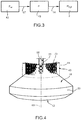
- reference numeral 1 indicates a fuel electro-injector (shown in a simplified manner) forming part of a high-pressure fuel injection system, for injecting fuel into a combustion chamber 2 (schematically shown in Figure 3 ) of an internal combustion engine.
- the injection system is of the common rail type, for a diesel-cycle internal combustion engine.
- the electro-injector 1 comprises an injector body 4, which extends along a longitudinal axis 5, is preferably formed by a number of pieces fastened together, and has an inlet 6 to receive fuel supplied at high pressure, in particular at a pressure in the range between 600 and 2800 bar.
- the inlet 6 is connected, in a manner not shown, to a common rail, which in turn is connected to a high-pressure pump (not shown), also forming part of the injection system.
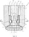
- the electro-injector 1 ends with a fuel atomizer 10 comprising a nozzle 11, which is fastened to the injector body 4 and has a feedthrough seat 13 along axis 5.
- the atomizer 10 also comprises a valve needle 12, which extends along axis 5 and is axially movable in the seat 13 for opening/closing the nozzle 11, by performing an opening stroke, or lift, directed axially outwards from the seat 13, and a closing stroke directed axially towards the inside of the nozzle 11 and the injector body 4.
- the nozzle 11 has a sealing seat 21, which, together with a head 20 of the valve needle 12, defines a discharge section 14 for the fuel.
- the discharge section 14 has a continuous, circular, ring-like shape, with a width that is constant along the circumference, but which continuously increases as the opening stroke of the valve needle 12 proceeds.
- the sealing seat 21 is not defined by a sharp-edged surface, but by a circular ring with a chamfered or radiused surface, which connects together a front surface 17, external to the seat 13 and to the sealing seat 21, and a cylindrical surface 18 of the seat 13.
- the chamfered or radiused surface of the sealing seat 21 reduces the pressure or specific load of the head 20 on the nozzle 11 during closure and therefore reduces stress and risks of fatigue failure.
- the head 20 has an external diameter larger than the maximum diameter of the sealing seat 21 and of the remaining part of the valve needle 12. Near the nozzle 11, the head 20 is delimited by a surface 19 suitable for shutting against the sealing seat 21 and defined by a truncated cone or a convex segment of a sphere symmetrical with respect to axis 5. These two components, when mated in contact, define a single "static seal", i.e. a seal that guarantees perfect closure of the outlet of the nozzle 11.
- the sealing seat 21 and the valve needle 12 are sized so as to define a discharge section 14 that varies continuously, and not in a step-wise discrete manner, as the axial position of the valve needle 12 varies.
- the outward opening stroke of the valve needle 12 causes an initial opening of the nozzle 11 and then a progressive increase in the discharge section 14 for the fuel.
- the discharge section 14 With a relatively small opening stroke, the discharge section 14 is also relatively small, and so the fuel is injected with high atomization and a spray characterized by lower penetration.
- the discharge section 14 is also relatively large.
- the fuel is injected with a spray characterized by high penetration.
- the atomizer 10 has an annular passageway 16, which is radially defined by a stem 41 of the valve needle 12 and by the seat 13 of the nozzle 11.
- the annular passageway 16 comprises an end zone 42 that permanently communicates with the inlet 6 through at least one passage (not shown), made in the injector body 4 and in the nozzle 11, thereby defining a high-pressure environment.
- the end zone 42 is defined by an annular chamber, generally known as a "cardioid" and having a wider cross-section than the remaining part of the annular passageway 16.
- the nozzle 11 comprises a rear guide portion 46 having a guide hole 47, defined by an area of the seat 13 and engaged in an axially sliding manner by a slider portion 25 of the valve needle 12.
- the diameter of surface 18 at the chamber 43 is equal to that of the guide hole 47, while in the other zones of the annular passageway 16 the internal diameter of the seat 13 is greater than or equal to this value.
- the average diameter of the sealing seat 21 is slightly larger than the diameter of the guide hole 47 and of surface 18. Therefore, the difference between the diameter of the dynamic seal at the guide hole 47 and the average diameter of the static seal at the sealing seat 21 causes an imbalance in the axial forces exerted by the fuel pressure on the valve needle 12 when the nozzle 11 is closed by the head 20 of the valve needle 12: in any case, this is a controlled imbalance predetermined by design, which must not exceed the force exerted by the spring 54 (described hereinafter).
- the relation between the average diameter of the sealing seat 21 and the diameter of the guide hole 47 is different from that indicated above for the preferred embodiments discussed and illustrated herein.
- the electro-injector 1 comprises an actuator device 50, in turn comprising an electrically-controlled actuator 51, i.e. an actuator controlled by an electronic control unit (not shown) that is programmed, for each step of injecting fuel and the associated combustion cycle in the combustion chamber 2, to supply the actuator 51 with one or more electric control signals to perform corresponding injections of fuel.
- an electrically-controlled actuator 51 i.e. an actuator controlled by an electronic control unit (not shown) that is programmed, for each step of injecting fuel and the associated combustion cycle in the combustion chamber 2, to supply the actuator 51 with one or more electric control signals to perform corresponding injections of fuel.
- the type of actuator 51 is such as to define an axial displacement proportional to the electric control signal received: for example, the actuator 51 could be defined by a piezoelectro-actuator or by a magnetostrictive actuator.
- the actuator device 50 further comprises a spring 52, which is preloaded to exert axial compression on the actuator 51 to increase efficiency.
- the passages 67 comprise respective end portions 68, which exit directly into the annular chamber 43 and extend along respective axes 69 parallel to axis 5, with areas of passage that are constant along these axes 69. In this way, portions 68 cause the canalization or guiding of the respective fuel flows, which then exit into the annular chamber 43, and do not give any swirling motion to these fuel flows in the annular chamber 43.
- passages 67 also comprise respective initial portions 70, which define a larger area of passage than portions 68 and are connected to portions 68 by respective intermediate portions 71.
- the latter define a taper, with an area of passage that decreases, preferably in a progressive manner (without steps), up to the inlet of portions 68 to limit pressure losses at this inlet.
- each pair of portions 70 and 71 is aligned with the respective portion 68 along axis 69.
- the passages 67 do not have the function of determining the flow of fuel delivered. In fact, their function is rather that of converting part of the pressure in velocity of the fuel inside the annular chamber 43, without a substantial drop in total fuel pressure (the conservation of total pressure depends, as explained further on, on the viscous friction of the fluid).
- the area of passage at the discharge section 14 is approximately 0.15 mm 2 : by applying the conservation law of the flow in portions 68 and in the discharge section 14 and making use of Bernoulli's theorem applied between the inlet of passages 67 and the outlets in the annular chamber 43, and also Bernoulli's theorem applied between the inlet of passages 67 and the discharge section 14, setting the pressure at the outlet of portions 68 to be at least 65% of the inlet pressure, and also ignoring the losses due to viscous friction and/or thermal dissipation and considering the fluid to be incompressible, it is possible to write a three-equation system with three unknowns (fluid velocity through passages 67, fluid velocity through the discharge section 14 and the overall area of passage in portions 68).
- the pressure at the outlet of portions 68 will be approximately 650 bar and the velocity through the discharge section 14 will be approximately 365 m/s, while the velocity at the outlets of the annular chamber 43 will be approximately 210 m/s.
- passages 67 define a hydraulic resistance and cause a drop in total pressure between the end zone 42 and the annular chamber 43 when fuel flows.
- the discharge section 14 defines another hydraulic resistance, which is adjustable by varying the lift of the valve needle 12: hence, if it is wished to take these energy losses into account, it is necessary to increase the maximum permitted value for the pressure drop across portions 68 by approximately 10%, and so the maximum permitted value for the pressure drop across passages 67 is 45%, noting that the predominant part consists in the conversion of pressure into kinetic energy of the fuel.
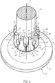
- outlets of portions 68 of passages 67 are identified in Figures 2 and 4 by reference numerals 72: when the nozzle 11 is open, the fuel leaving the passages 67 locally has a higher velocity at the outlets 72 with respect to the fuel in the annular chamber 43 in points 73 that are intermediate between the outlets 72 along the same circumference (as can be inferred from the flow lines that are schematically indicated in Figure 4 and derived from computer simulations).
- the fuel film that leaves the discharge section 14 is not homogeneous in terms of modulus of velocity, but has faster portions, those corresponding to the radial planes on which the axes 69 of passages 67 lie, and slower zones, in the intermediate angular positions between passages 67.
- fuel particles along flow lines L1 travel a longer distance to reach the discharge section 14 with respect to fuel particles along flow lines L2, which instead have a more direct path: this entails a slowing down along flow lines L1 with respect to L2.
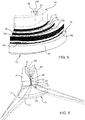
- the spray is substantially uniform along the circumference; in the moments following, as shown in Figure 8 , the fuel spray pattern acquires a shape constituted by an umbrella-shaped central part 77 and a plurality of cusps or tentacles 78, that are equal in number to the number of passages 67 and protrude from the outside edge of the central part 77. It is therefore evident that the fluid streams that form spray portions 75 contribute with the fluid streams of spray portions 76 to form the cusps 78, with a higher penetration in the combustion chamber 2.
- penetration of the cusps 78 is increased and the diameter of the central part 77 is reduced by opportune choices in the shape/size of the cross-section of portions 68 and, where necessary, by an opportune choice of the number of passages 67.
- each of the spray portions 75 tends to split into two sub-portions 75a and 75b, basically due to the effect of the opposing resistance of the air in the combustion chamber 2.
- the sub-portions 75a and 75b generated by a given channel 67 progressively move apart from each other in a circumferential direction, inside portions 76, as the distance of the fuel from the discharge section 14 increases. In other words, it is as if the flow lines followed by the fuel at higher velocity become sucked in a circumferential direction towards the zones where the fuel has a lower velocity.
- a further factor that can affect the uniform or non-uniform velocity profile of the fuel along the discharge section 14 is given by the minimum area of passage of each channel 67, as mentioned above. In fact, as this minimum area of passage decreases, it is possible to achieve a higher fuel velocity at the outlet 72 and, consequently, more marked canalization and differentiation of the flow lines (L1 and L2) in the annular chamber 43, in the passage of fuel going from the outlet 72 to the discharge section 14.
- the air supercharging pressure (pcyl) and the fuel supply pressure (prail) are known and/or controllable.
- the atomizer 10 can be obtained through the following design steps:
- each portion 68 is considered to be radially delimited by an inner surface or bottom surface 80 (radially closer to axis 5 and forming part of the stem 41) and by an outer surface 82 (radially further away from axis 5 and forming part of surface 66).
- each portion 68 is delimited in a circumferential direction by two sides 83 facing each other.
- a value greater than or equal to two is chosen for the ratio between the depth P in the radial direction and the outer chord C of the cross-section of each portion 68.
- depth means the radial distance between surfaces 80 and 82
- outer chord means the distance in a tangential direction between the ends of sides 83 on surface 82.
- this narrow and deep shape at the outlets 72 enables significantly limiting the diameter of the central portion 77 and increasing the penetration of the cusps 78, as it performs a more significant guide function for the streams leaving the passages 67.
- the number of passages 67 also affects reduction in the diameter of the central portion 77 and/or increasing the penetration of the cusps 78.
- this number is advantageously chosen between 8 and 15. Values close to 15 can be set in supply systems in which the maximum supply pressure (pmax) in the common rail is higher, in which the maximum flow rate required from the atomizer 10 is greater, or in which the seal diameter of the valve needle 12 is larger.
- the size of the combustion chamber must also be taken into consideration when choosing the number of passages 67.
- each portion 68 is also optimized.
- this particular spray shape enables obtaining a traditional mode of the CI (Compressed ignition) type, especially at high loads, i.e. high fuel penetration in the combustion chamber 2, in a similar manner to what happens with atomizers of the known art with a solid-cone spray.
- CI Compressed ignition
- HCCI Homogeneous-Charge Compression-Ignition
- the supply pressure can be reduced so as to lower fuel velocity at the outlets 72 and/or a relatively low lift can be set for the valve needle 12 to have greater back pressure in the annular chamber 43.
- the annular chamber 43 can make the velocity of the fuel uniform to obtain a substantially uniform modulus of velocity in the circular direction along the discharge section 14 in the low and medium load operating conditions of the engine.
- the lateral drift of the flow lines L2 downstream of the discharge section 14 also causes a partial build-up or coalescence of fuel drops at higher velocities. These drops thus tend to increase in volume in the first part of their path. Thanks to this partial coalescence, the drops that will form the cusps 78 are larger and therefore characterized by greater kinetic energy and a higher Weber number with respect to those in a spray with a substantially constant modulus of velocity along the circumference. It follows that the fuel drops that will form the cusps 78 are more easily subject to fragmentation into smaller drops in the second part of their path, i.e. precisely in the cusps 78. In other words, the behaviour of the fuel drops that form the cusps 78 verges decidedly close to what happens with fuel drops delivered by atomizers of the known art with a solid-cone spray.
- the increased depth of the intermediate portions 71 enables reducing energy losses of the flow while passing through the passages 67.
- the geometry of the annular chamber 43 could be sized so as to have a shape in the circumferential direction that is not homogeneous or constant, i.e. a variable cross-section so as favour canalization and therefore the nonuniformity of the flow lines in the annular chamber 43.
- the nozzle 11 could be defined by an end portion of the injector body 4, without being a separate piece from the latter, and/or the guide portion 46 could form part of a body separate from the nozzle 11, and/or the valve needle 12 could be operated directly, i.e. the injector 1 might lack the pressure chamber 62.
- the shape of the annular chamber 43 could be different from that shown in section in the drawings enclosed by way of example, possibly through shaping the inner surface of seat 13 of the nozzle 11 (alternatively or in combination with shaping of the stem 41 of the valve needle 12).
- passages 67 could be constituted by just portions 68, i.e. have an area of passage that is constant along axes 69 and so lack portions 70 and 71.
- sectors 65 could constitute part of the nozzle 11 so as to define a step-shaped and not cylindrical surface 66, and be coupled to the stem 41 in a sliding manner.
- a solenoid actuator could be used that, even though basically operating only in two or three discrete positions, could be capable of generating the desired spray, for example by regulating the injection pressure and/or the actuation time of the electromagnet.
- the atomizer 10 could be applied to fuels other than diesel fuel, and so it might be necessary to set different dimensions for the annular chamber 43 and/or the passages 67 to obtain a non-uniform velocity profile for the fuel along the discharge section 14 and therefore the same effect resulting from the cusps 78 shown in the accompanying drawings.
- passages 67 could be arranged in non-uniform positions around axis 5, for example closer to each other in the zone of the combustion chamber 2 where greater spray penetration is required. Especially in this case, it is also possible to obtain asymmetry in the width or penetration of the cusps 78 in the same spray.
Landscapes
- Engineering & Computer Science (AREA)
- Chemical & Material Sciences (AREA)
- Combustion & Propulsion (AREA)
- Mechanical Engineering (AREA)
- General Engineering & Computer Science (AREA)
- Fuel-Injection Apparatus (AREA)
Priority Applications (2)
| Application Number | Priority Date | Filing Date | Title |
|---|---|---|---|
| EP16425092.0A EP3299610B1 (de) | 2016-09-22 | 2016-09-22 | Kraftstoffelektroeinspritzerzerstäuber, insbesondere für einen dieselmotor |
| US15/711,671 US11008991B2 (en) | 2016-09-22 | 2017-09-21 | Fuel electro-injector atomizer, in particular for a diesel cycle engine |
Applications Claiming Priority (1)
| Application Number | Priority Date | Filing Date | Title |
|---|---|---|---|
| EP16425092.0A EP3299610B1 (de) | 2016-09-22 | 2016-09-22 | Kraftstoffelektroeinspritzerzerstäuber, insbesondere für einen dieselmotor |
Publications (2)
| Publication Number | Publication Date |
|---|---|
| EP3299610A1 true EP3299610A1 (de) | 2018-03-28 |
| EP3299610B1 EP3299610B1 (de) | 2020-03-04 |
Family
ID=57460458
Family Applications (1)
| Application Number | Title | Priority Date | Filing Date |
|---|---|---|---|
| EP16425092.0A Active EP3299610B1 (de) | 2016-09-22 | 2016-09-22 | Kraftstoffelektroeinspritzerzerstäuber, insbesondere für einen dieselmotor |
Country Status (2)
| Country | Link |
|---|---|
| US (1) | US11008991B2 (de) |
| EP (1) | EP3299610B1 (de) |
Families Citing this family (1)
| Publication number | Priority date | Publication date | Assignee | Title |
|---|---|---|---|---|
| CN109041007B (zh) * | 2018-08-10 | 2021-09-28 | 中国联合网络通信集团有限公司 | 一种通信小区的参数配置方法和装置 |
Citations (7)
| Publication number | Priority date | Publication date | Assignee | Title |
|---|---|---|---|---|
| US2263197A (en) * | 1939-03-08 | 1941-11-18 | Eisemann Magneto Corp | Fuel injection nozzle |
| JPH0169180U (de) * | 1987-10-27 | 1989-05-08 | ||
| US5829688A (en) | 1996-01-13 | 1998-11-03 | Robert Bosch Gmbh | Injection valve for directly injecting fuel into an internal combustion engine |
| EP0879953A1 (de) * | 1997-05-23 | 1998-11-25 | Honda Giken Kogyo Kabushiki Kaisha | Verfahren zur Bestimmung der magnetischen Kraft der elektromagnetischen Spule zum Öffnen und Schliessen eines Luft-Kraftstoff-Gemischventils |
| EP1559904A1 (de) | 2004-01-28 | 2005-08-03 | Siemens VDO Automotive S.p.A. | Ventilkörper, Fluidinjektor und Herstellungsmethode für einen Ventilkörper |
| EP1734250A1 (de) * | 2005-06-15 | 2006-12-20 | Denso Corporation | Kraftstoffeinspritzventil |
| EP3018340A1 (de) * | 2014-11-05 | 2016-05-11 | C.R.F. Società Consortile per Azioni | Elektrische kraftstoffeinspritzdüse für ein einspritzsystem eines verbrennungsmotors |
Family Cites Families (4)
| Publication number | Priority date | Publication date | Assignee | Title |
|---|---|---|---|---|
| GB388532A (en) * | 1959-07-02 | 1933-03-02 | Keith Dudley Ulysses Rogers | Improvements in or relating to the reception of radio telephony, telegraphy or television |
| CA1289429C (en) * | 1985-07-19 | 1991-09-24 | Roy Stanley Brooks | Nozzles for fuel injection systems |
| KR101144482B1 (ko) * | 2010-10-06 | 2012-05-11 | (주)제너진 | 엔진의 직분사 인젝터 |
| EP3165759A1 (de) | 2015-11-09 | 2017-05-10 | C.R.F. Società Consortile Per Azioni | Einspritzverfahren zum einspritzen von kraftstoff in die brennkammer eines verbrennungsmotors, zerstäuber eines kraftstoffelektroinjektors zur durchführung solch eines einspritzverfahrens und verfahren zur herstellung solch eines zerstäubers |
-
2016
- 2016-09-22 EP EP16425092.0A patent/EP3299610B1/de active Active
-
2017
- 2017-09-21 US US15/711,671 patent/US11008991B2/en active Active
Patent Citations (7)
| Publication number | Priority date | Publication date | Assignee | Title |
|---|---|---|---|---|
| US2263197A (en) * | 1939-03-08 | 1941-11-18 | Eisemann Magneto Corp | Fuel injection nozzle |
| JPH0169180U (de) * | 1987-10-27 | 1989-05-08 | ||
| US5829688A (en) | 1996-01-13 | 1998-11-03 | Robert Bosch Gmbh | Injection valve for directly injecting fuel into an internal combustion engine |
| EP0879953A1 (de) * | 1997-05-23 | 1998-11-25 | Honda Giken Kogyo Kabushiki Kaisha | Verfahren zur Bestimmung der magnetischen Kraft der elektromagnetischen Spule zum Öffnen und Schliessen eines Luft-Kraftstoff-Gemischventils |
| EP1559904A1 (de) | 2004-01-28 | 2005-08-03 | Siemens VDO Automotive S.p.A. | Ventilkörper, Fluidinjektor und Herstellungsmethode für einen Ventilkörper |
| EP1734250A1 (de) * | 2005-06-15 | 2006-12-20 | Denso Corporation | Kraftstoffeinspritzventil |
| EP3018340A1 (de) * | 2014-11-05 | 2016-05-11 | C.R.F. Società Consortile per Azioni | Elektrische kraftstoffeinspritzdüse für ein einspritzsystem eines verbrennungsmotors |
Also Published As
| Publication number | Publication date |
|---|---|
| EP3299610B1 (de) | 2020-03-04 |
| US20180080423A1 (en) | 2018-03-22 |
| US11008991B2 (en) | 2021-05-18 |
Similar Documents
| Publication | Publication Date | Title |
|---|---|---|
| US5299919A (en) | Fuel injector system | |
| US7404526B2 (en) | Injection nozzle | |
| RU2468242C2 (ru) | Дроссель на игле распылителя топливной форсунки для двигателя внутреннего сгорания | |
| US6601566B2 (en) | Fuel injector with directly controlled dual concentric check and engine using same | |
| CN101680413B (zh) | 用于燃料喷射阀的控制阀 | |
| KR101894524B1 (ko) | 내연 기관의 연료 분사 시스템용 연료 전자 인젝터 | |
| US5522545A (en) | Hydraulically actuated fuel injector | |
| EP2302197B1 (de) | Brennstoffeinspritzventil und brennstoffeinspritzvorrichtung | |
| CN103967671A (zh) | 一种双阀可变喷孔面积燃油喷嘴 | |
| CN102812232B (zh) | 用于内燃机的高压燃料喷射阀 | |
| KR100427569B1 (ko) | 내연기관용연료인젝터 | |
| CN101910605A (zh) | 降低了操作中随时间的变化的发动机和控制阀组件 | |
| US11008991B2 (en) | Fuel electro-injector atomizer, in particular for a diesel cycle engine | |
| US20070023545A1 (en) | Injection nozzle | |
| US20030116660A1 (en) | Nozzle insert for dual mode fuel injector | |
| GB2367330A (en) | Common-rail fuel injector | |
| US20160230728A1 (en) | Plunger And Fluid-Line System | |
| CN205532965U (zh) | 一种新型共轨喷油器 | |
| CN105971793B (zh) | 用于实现快速断油的电控高压喷油器 | |
| EP3165759A1 (de) | Einspritzverfahren zum einspritzen von kraftstoff in die brennkammer eines verbrennungsmotors, zerstäuber eines kraftstoffelektroinjektors zur durchführung solch eines einspritzverfahrens und verfahren zur herstellung solch eines zerstäubers | |
| CN100480505C (zh) | 用于内燃机的燃料喷射阀 | |
| JP6496458B2 (ja) | 燃料インジェクタ | |
| WO2016071853A1 (en) | Fuel electro-injector atomizer for a fuel injection system for an internal combustion engine | |
| EP1566538B1 (de) | Einspritzdüse | |
| CN107514328B (zh) | 一种用于双燃料发动机的微喷电控喷油器 |
Legal Events
| Date | Code | Title | Description |
|---|---|---|---|
| PUAI | Public reference made under article 153(3) epc to a published international application that has entered the european phase |
Free format text: ORIGINAL CODE: 0009012 |
|
| STAA | Information on the status of an ep patent application or granted ep patent |
Free format text: STATUS: THE APPLICATION HAS BEEN PUBLISHED |
|
| AK | Designated contracting states |
Kind code of ref document: A1 Designated state(s): AL AT BE BG CH CY CZ DE DK EE ES FI FR GB GR HR HU IE IS IT LI LT LU LV MC MK MT NL NO PL PT RO RS SE SI SK SM TR |
|
| AX | Request for extension of the european patent |
Extension state: BA ME |
|
| STAA | Information on the status of an ep patent application or granted ep patent |
Free format text: STATUS: REQUEST FOR EXAMINATION WAS MADE |
|
| 17P | Request for examination filed |
Effective date: 20180928 |
|
| RBV | Designated contracting states (corrected) |
Designated state(s): AL AT BE BG CH CY CZ DE DK EE ES FI FR GB GR HR HU IE IS IT LI LT LU LV MC MK MT NL NO PL PT RO RS SE SI SK SM TR |
|
| GRAP | Despatch of communication of intention to grant a patent |
Free format text: ORIGINAL CODE: EPIDOSNIGR1 |
|
| STAA | Information on the status of an ep patent application or granted ep patent |
Free format text: STATUS: GRANT OF PATENT IS INTENDED |
|
| RIC1 | Information provided on ipc code assigned before grant |
Ipc: F02M 61/06 20060101AFI20190809BHEP Ipc: F02M 61/08 20060101ALI20190809BHEP Ipc: F02M 61/16 20060101ALI20190809BHEP Ipc: F02M 61/12 20060101ALI20190809BHEP Ipc: F02M 61/18 20060101ALI20190809BHEP |
|
| INTG | Intention to grant announced |
Effective date: 20190917 |
|
| GRAS | Grant fee paid |
Free format text: ORIGINAL CODE: EPIDOSNIGR3 |
|
| GRAA | (expected) grant |
Free format text: ORIGINAL CODE: 0009210 |
|
| STAA | Information on the status of an ep patent application or granted ep patent |
Free format text: STATUS: THE PATENT HAS BEEN GRANTED |
|
| AK | Designated contracting states |
Kind code of ref document: B1 Designated state(s): AL AT BE BG CH CY CZ DE DK EE ES FI FR GB GR HR HU IE IS IT LI LT LU LV MC MK MT NL NO PL PT RO RS SE SI SK SM TR |
|
| REG | Reference to a national code |
Ref country code: GB Ref legal event code: FG4D |
|
| REG | Reference to a national code |
Ref country code: CH Ref legal event code: EP |
|
| REG | Reference to a national code |
Ref country code: AT Ref legal event code: REF Ref document number: 1240653 Country of ref document: AT Kind code of ref document: T Effective date: 20200315 |
|
| REG | Reference to a national code |
Ref country code: DE Ref legal event code: R096 Ref document number: 602016030977 Country of ref document: DE |
|
| REG | Reference to a national code |
Ref country code: IE Ref legal event code: FG4D |
|
| PG25 | Lapsed in a contracting state [announced via postgrant information from national office to epo] |
Ref country code: NO Free format text: LAPSE BECAUSE OF FAILURE TO SUBMIT A TRANSLATION OF THE DESCRIPTION OR TO PAY THE FEE WITHIN THE PRESCRIBED TIME-LIMIT Effective date: 20200604 Ref country code: FI Free format text: LAPSE BECAUSE OF FAILURE TO SUBMIT A TRANSLATION OF THE DESCRIPTION OR TO PAY THE FEE WITHIN THE PRESCRIBED TIME-LIMIT Effective date: 20200304 Ref country code: RS Free format text: LAPSE BECAUSE OF FAILURE TO SUBMIT A TRANSLATION OF THE DESCRIPTION OR TO PAY THE FEE WITHIN THE PRESCRIBED TIME-LIMIT Effective date: 20200304 |
|
| REG | Reference to a national code |
Ref country code: NL Ref legal event code: MP Effective date: 20200304 |
|
| PG25 | Lapsed in a contracting state [announced via postgrant information from national office to epo] |
Ref country code: HR Free format text: LAPSE BECAUSE OF FAILURE TO SUBMIT A TRANSLATION OF THE DESCRIPTION OR TO PAY THE FEE WITHIN THE PRESCRIBED TIME-LIMIT Effective date: 20200304 Ref country code: BG Free format text: LAPSE BECAUSE OF FAILURE TO SUBMIT A TRANSLATION OF THE DESCRIPTION OR TO PAY THE FEE WITHIN THE PRESCRIBED TIME-LIMIT Effective date: 20200604 Ref country code: LV Free format text: LAPSE BECAUSE OF FAILURE TO SUBMIT A TRANSLATION OF THE DESCRIPTION OR TO PAY THE FEE WITHIN THE PRESCRIBED TIME-LIMIT Effective date: 20200304 Ref country code: GR Free format text: LAPSE BECAUSE OF FAILURE TO SUBMIT A TRANSLATION OF THE DESCRIPTION OR TO PAY THE FEE WITHIN THE PRESCRIBED TIME-LIMIT Effective date: 20200605 Ref country code: SE Free format text: LAPSE BECAUSE OF FAILURE TO SUBMIT A TRANSLATION OF THE DESCRIPTION OR TO PAY THE FEE WITHIN THE PRESCRIBED TIME-LIMIT Effective date: 20200304 |
|
| REG | Reference to a national code |
Ref country code: LT Ref legal event code: MG4D |
|
| PG25 | Lapsed in a contracting state [announced via postgrant information from national office to epo] |
Ref country code: NL Free format text: LAPSE BECAUSE OF FAILURE TO SUBMIT A TRANSLATION OF THE DESCRIPTION OR TO PAY THE FEE WITHIN THE PRESCRIBED TIME-LIMIT Effective date: 20200304 |
|
| PG25 | Lapsed in a contracting state [announced via postgrant information from national office to epo] |
Ref country code: LT Free format text: LAPSE BECAUSE OF FAILURE TO SUBMIT A TRANSLATION OF THE DESCRIPTION OR TO PAY THE FEE WITHIN THE PRESCRIBED TIME-LIMIT Effective date: 20200304 Ref country code: EE Free format text: LAPSE BECAUSE OF FAILURE TO SUBMIT A TRANSLATION OF THE DESCRIPTION OR TO PAY THE FEE WITHIN THE PRESCRIBED TIME-LIMIT Effective date: 20200304 Ref country code: PT Free format text: LAPSE BECAUSE OF FAILURE TO SUBMIT A TRANSLATION OF THE DESCRIPTION OR TO PAY THE FEE WITHIN THE PRESCRIBED TIME-LIMIT Effective date: 20200729 Ref country code: SM Free format text: LAPSE BECAUSE OF FAILURE TO SUBMIT A TRANSLATION OF THE DESCRIPTION OR TO PAY THE FEE WITHIN THE PRESCRIBED TIME-LIMIT Effective date: 20200304 Ref country code: IS Free format text: LAPSE BECAUSE OF FAILURE TO SUBMIT A TRANSLATION OF THE DESCRIPTION OR TO PAY THE FEE WITHIN THE PRESCRIBED TIME-LIMIT Effective date: 20200704 Ref country code: CZ Free format text: LAPSE BECAUSE OF FAILURE TO SUBMIT A TRANSLATION OF THE DESCRIPTION OR TO PAY THE FEE WITHIN THE PRESCRIBED TIME-LIMIT Effective date: 20200304 Ref country code: RO Free format text: LAPSE BECAUSE OF FAILURE TO SUBMIT A TRANSLATION OF THE DESCRIPTION OR TO PAY THE FEE WITHIN THE PRESCRIBED TIME-LIMIT Effective date: 20200304 Ref country code: SK Free format text: LAPSE BECAUSE OF FAILURE TO SUBMIT A TRANSLATION OF THE DESCRIPTION OR TO PAY THE FEE WITHIN THE PRESCRIBED TIME-LIMIT Effective date: 20200304 Ref country code: ES Free format text: LAPSE BECAUSE OF FAILURE TO SUBMIT A TRANSLATION OF THE DESCRIPTION OR TO PAY THE FEE WITHIN THE PRESCRIBED TIME-LIMIT Effective date: 20200304 |
|
| REG | Reference to a national code |
Ref country code: AT Ref legal event code: MK05 Ref document number: 1240653 Country of ref document: AT Kind code of ref document: T Effective date: 20200304 |
|
| REG | Reference to a national code |
Ref country code: DE Ref legal event code: R097 Ref document number: 602016030977 Country of ref document: DE |
|
| PLBE | No opposition filed within time limit |
Free format text: ORIGINAL CODE: 0009261 |
|
| STAA | Information on the status of an ep patent application or granted ep patent |
Free format text: STATUS: NO OPPOSITION FILED WITHIN TIME LIMIT |
|
| PG25 | Lapsed in a contracting state [announced via postgrant information from national office to epo] |
Ref country code: AT Free format text: LAPSE BECAUSE OF FAILURE TO SUBMIT A TRANSLATION OF THE DESCRIPTION OR TO PAY THE FEE WITHIN THE PRESCRIBED TIME-LIMIT Effective date: 20200304 Ref country code: DK Free format text: LAPSE BECAUSE OF FAILURE TO SUBMIT A TRANSLATION OF THE DESCRIPTION OR TO PAY THE FEE WITHIN THE PRESCRIBED TIME-LIMIT Effective date: 20200304 |
|
| 26N | No opposition filed |
Effective date: 20201207 |
|
| PG25 | Lapsed in a contracting state [announced via postgrant information from national office to epo] |
Ref country code: SI Free format text: LAPSE BECAUSE OF FAILURE TO SUBMIT A TRANSLATION OF THE DESCRIPTION OR TO PAY THE FEE WITHIN THE PRESCRIBED TIME-LIMIT Effective date: 20200304 Ref country code: PL Free format text: LAPSE BECAUSE OF FAILURE TO SUBMIT A TRANSLATION OF THE DESCRIPTION OR TO PAY THE FEE WITHIN THE PRESCRIBED TIME-LIMIT Effective date: 20200304 |
|
| REG | Reference to a national code |
Ref country code: CH Ref legal event code: PL |
|
| GBPC | Gb: european patent ceased through non-payment of renewal fee |
Effective date: 20200922 |
|
| REG | Reference to a national code |
Ref country code: BE Ref legal event code: MM Effective date: 20200930 |
|
| PG25 | Lapsed in a contracting state [announced via postgrant information from national office to epo] |
Ref country code: LU Free format text: LAPSE BECAUSE OF NON-PAYMENT OF DUE FEES Effective date: 20200922 |
|
| PG25 | Lapsed in a contracting state [announced via postgrant information from national office to epo] |
Ref country code: BE Free format text: LAPSE BECAUSE OF NON-PAYMENT OF DUE FEES Effective date: 20200930 Ref country code: CH Free format text: LAPSE BECAUSE OF NON-PAYMENT OF DUE FEES Effective date: 20200930 Ref country code: LI Free format text: LAPSE BECAUSE OF NON-PAYMENT OF DUE FEES Effective date: 20200930 Ref country code: GB Free format text: LAPSE BECAUSE OF NON-PAYMENT OF DUE FEES Effective date: 20200922 Ref country code: IE Free format text: LAPSE BECAUSE OF NON-PAYMENT OF DUE FEES Effective date: 20200922 |
|
| PG25 | Lapsed in a contracting state [announced via postgrant information from national office to epo] |
Ref country code: TR Free format text: LAPSE BECAUSE OF FAILURE TO SUBMIT A TRANSLATION OF THE DESCRIPTION OR TO PAY THE FEE WITHIN THE PRESCRIBED TIME-LIMIT Effective date: 20200304 Ref country code: MT Free format text: LAPSE BECAUSE OF FAILURE TO SUBMIT A TRANSLATION OF THE DESCRIPTION OR TO PAY THE FEE WITHIN THE PRESCRIBED TIME-LIMIT Effective date: 20200304 Ref country code: CY Free format text: LAPSE BECAUSE OF FAILURE TO SUBMIT A TRANSLATION OF THE DESCRIPTION OR TO PAY THE FEE WITHIN THE PRESCRIBED TIME-LIMIT Effective date: 20200304 |
|
| PG25 | Lapsed in a contracting state [announced via postgrant information from national office to epo] |
Ref country code: MK Free format text: LAPSE BECAUSE OF FAILURE TO SUBMIT A TRANSLATION OF THE DESCRIPTION OR TO PAY THE FEE WITHIN THE PRESCRIBED TIME-LIMIT Effective date: 20200304 Ref country code: MC Free format text: LAPSE BECAUSE OF FAILURE TO SUBMIT A TRANSLATION OF THE DESCRIPTION OR TO PAY THE FEE WITHIN THE PRESCRIBED TIME-LIMIT Effective date: 20200304 Ref country code: AL Free format text: LAPSE BECAUSE OF FAILURE TO SUBMIT A TRANSLATION OF THE DESCRIPTION OR TO PAY THE FEE WITHIN THE PRESCRIBED TIME-LIMIT Effective date: 20200304 |
|
| PGFP | Annual fee paid to national office [announced via postgrant information from national office to epo] |
Ref country code: IT Payment date: 20230822 Year of fee payment: 8 |
|
| PGFP | Annual fee paid to national office [announced via postgrant information from national office to epo] |
Ref country code: FR Payment date: 20230822 Year of fee payment: 8 Ref country code: DE Payment date: 20230822 Year of fee payment: 8 |