EP3299607B1 - Procédé de fonctionnement d'un moteur ayant une sous-chambre pilote dans des conditions de charge partielle - Google Patents
Procédé de fonctionnement d'un moteur ayant une sous-chambre pilote dans des conditions de charge partielle Download PDFInfo
- Publication number
- EP3299607B1 EP3299607B1 EP17192456.6A EP17192456A EP3299607B1 EP 3299607 B1 EP3299607 B1 EP 3299607B1 EP 17192456 A EP17192456 A EP 17192456A EP 3299607 B1 EP3299607 B1 EP 3299607B1
- Authority
- EP
- European Patent Office
- Prior art keywords
- main
- pilot
- fuel
- combustion chambers
- maximum
- Prior art date
- Legal status (The legal status is an assumption and is not a legal conclusion. Google has not performed a legal analysis and makes no representation as to the accuracy of the status listed.)
- Active
Links
- 238000000034 method Methods 0.000 title claims description 21
- 239000000446 fuel Substances 0.000 claims description 102
- 238000002485 combustion reaction Methods 0.000 claims description 84
- 238000002347 injection Methods 0.000 claims description 43
- 239000007924 injection Substances 0.000 claims description 43
- 238000004891 communication Methods 0.000 claims description 9
- 230000002093 peripheral effect Effects 0.000 description 14
- 238000006073 displacement reaction Methods 0.000 description 6
- 230000000717 retained effect Effects 0.000 description 6
- 230000006835 compression Effects 0.000 description 5
- 238000007906 compression Methods 0.000 description 5
- 150000001875 compounds Chemical class 0.000 description 3
- 238000007789 sealing Methods 0.000 description 3
- 239000000203 mixture Substances 0.000 description 2
- 238000012986 modification Methods 0.000 description 2
- 230000004048 modification Effects 0.000 description 2
- 239000002551 biofuel Substances 0.000 description 1
- 230000001419 dependent effect Effects 0.000 description 1
- -1 diesel Substances 0.000 description 1
- 239000007789 gas Substances 0.000 description 1
- 239000003350 kerosene Substances 0.000 description 1
- 239000010687 lubricating oil Substances 0.000 description 1
- 239000002184 metal Substances 0.000 description 1
- 239000003921 oil Substances 0.000 description 1
- 239000007921 spray Substances 0.000 description 1
Images

Classifications
-
- F—MECHANICAL ENGINEERING; LIGHTING; HEATING; WEAPONS; BLASTING
- F02—COMBUSTION ENGINES; HOT-GAS OR COMBUSTION-PRODUCT ENGINE PLANTS
- F02B—INTERNAL-COMBUSTION PISTON ENGINES; COMBUSTION ENGINES IN GENERAL
- F02B19/00—Engines characterised by precombustion chambers
- F02B19/10—Engines characterised by precombustion chambers with fuel introduced partly into pre-combustion chamber, and partly into cylinder
- F02B19/1019—Engines characterised by precombustion chambers with fuel introduced partly into pre-combustion chamber, and partly into cylinder with only one pre-combustion chamber
- F02B19/1023—Engines characterised by precombustion chambers with fuel introduced partly into pre-combustion chamber, and partly into cylinder with only one pre-combustion chamber pre-combustion chamber and cylinder being fed with fuel-air mixture(s)
- F02B19/1071—Engines characterised by precombustion chambers with fuel introduced partly into pre-combustion chamber, and partly into cylinder with only one pre-combustion chamber pre-combustion chamber and cylinder being fed with fuel-air mixture(s) pre-combustion chamber having only one orifice,(i.e. an orifice by means of which it communicates with the cylinder); the intake system comprising two distinct intake conduits
-
- F—MECHANICAL ENGINEERING; LIGHTING; HEATING; WEAPONS; BLASTING
- F01—MACHINES OR ENGINES IN GENERAL; ENGINE PLANTS IN GENERAL; STEAM ENGINES
- F01C—ROTARY-PISTON OR OSCILLATING-PISTON MACHINES OR ENGINES
- F01C1/00—Rotary-piston machines or engines
- F01C1/22—Rotary-piston machines or engines of internal-axis type with equidirectional movement of co-operating members at the points of engagement, or with one of the co-operating members being stationary, the inner member having more teeth or tooth- equivalents than the outer member
-
- F—MECHANICAL ENGINEERING; LIGHTING; HEATING; WEAPONS; BLASTING
- F02—COMBUSTION ENGINES; HOT-GAS OR COMBUSTION-PRODUCT ENGINE PLANTS
- F02B—INTERNAL-COMBUSTION PISTON ENGINES; COMBUSTION ENGINES IN GENERAL
- F02B19/00—Engines characterised by precombustion chambers
- F02B19/10—Engines characterised by precombustion chambers with fuel introduced partly into pre-combustion chamber, and partly into cylinder
- F02B19/1004—Engines characterised by precombustion chambers with fuel introduced partly into pre-combustion chamber, and partly into cylinder details of combustion chamber, e.g. mounting arrangements
- F02B19/1014—Engines characterised by precombustion chambers with fuel introduced partly into pre-combustion chamber, and partly into cylinder details of combustion chamber, e.g. mounting arrangements design parameters, e.g. volume, torch passage cross sectional area, length, orientation, or the like
-
- F—MECHANICAL ENGINEERING; LIGHTING; HEATING; WEAPONS; BLASTING
- F02—COMBUSTION ENGINES; HOT-GAS OR COMBUSTION-PRODUCT ENGINE PLANTS
- F02B—INTERNAL-COMBUSTION PISTON ENGINES; COMBUSTION ENGINES IN GENERAL
- F02B19/00—Engines characterised by precombustion chambers
- F02B19/10—Engines characterised by precombustion chambers with fuel introduced partly into pre-combustion chamber, and partly into cylinder
- F02B19/1019—Engines characterised by precombustion chambers with fuel introduced partly into pre-combustion chamber, and partly into cylinder with only one pre-combustion chamber
- F02B19/108—Engines characterised by precombustion chambers with fuel introduced partly into pre-combustion chamber, and partly into cylinder with only one pre-combustion chamber with fuel injection at least into pre-combustion chamber, i.e. injector mounted directly in the pre-combustion chamber
-
- F—MECHANICAL ENGINEERING; LIGHTING; HEATING; WEAPONS; BLASTING
- F02—COMBUSTION ENGINES; HOT-GAS OR COMBUSTION-PRODUCT ENGINE PLANTS
- F02B—INTERNAL-COMBUSTION PISTON ENGINES; COMBUSTION ENGINES IN GENERAL
- F02B19/00—Engines characterised by precombustion chambers
- F02B19/12—Engines characterised by precombustion chambers with positive ignition
-
- F—MECHANICAL ENGINEERING; LIGHTING; HEATING; WEAPONS; BLASTING
- F02—COMBUSTION ENGINES; HOT-GAS OR COMBUSTION-PRODUCT ENGINE PLANTS
- F02B—INTERNAL-COMBUSTION PISTON ENGINES; COMBUSTION ENGINES IN GENERAL
- F02B53/00—Internal-combustion aspects of rotary-piston or oscillating-piston engines
-
- F—MECHANICAL ENGINEERING; LIGHTING; HEATING; WEAPONS; BLASTING
- F02—COMBUSTION ENGINES; HOT-GAS OR COMBUSTION-PRODUCT ENGINE PLANTS
- F02B—INTERNAL-COMBUSTION PISTON ENGINES; COMBUSTION ENGINES IN GENERAL
- F02B53/00—Internal-combustion aspects of rotary-piston or oscillating-piston engines
- F02B53/02—Methods of operating
-
- F—MECHANICAL ENGINEERING; LIGHTING; HEATING; WEAPONS; BLASTING
- F02—COMBUSTION ENGINES; HOT-GAS OR COMBUSTION-PRODUCT ENGINE PLANTS
- F02B—INTERNAL-COMBUSTION PISTON ENGINES; COMBUSTION ENGINES IN GENERAL
- F02B53/00—Internal-combustion aspects of rotary-piston or oscillating-piston engines
- F02B53/10—Fuel supply; Introducing fuel to combustion space
-
- F—MECHANICAL ENGINEERING; LIGHTING; HEATING; WEAPONS; BLASTING
- F02—COMBUSTION ENGINES; HOT-GAS OR COMBUSTION-PRODUCT ENGINE PLANTS
- F02B—INTERNAL-COMBUSTION PISTON ENGINES; COMBUSTION ENGINES IN GENERAL
- F02B53/00—Internal-combustion aspects of rotary-piston or oscillating-piston engines
- F02B53/12—Ignition
-
- F—MECHANICAL ENGINEERING; LIGHTING; HEATING; WEAPONS; BLASTING
- F02—COMBUSTION ENGINES; HOT-GAS OR COMBUSTION-PRODUCT ENGINE PLANTS
- F02D—CONTROLLING COMBUSTION ENGINES
- F02D41/00—Electrical control of supply of combustible mixture or its constituents
- F02D41/02—Circuit arrangements for generating control signals
- F02D41/04—Introducing corrections for particular operating conditions
- F02D41/045—Detection of accelerating or decelerating state
-
- F—MECHANICAL ENGINEERING; LIGHTING; HEATING; WEAPONS; BLASTING
- F02—COMBUSTION ENGINES; HOT-GAS OR COMBUSTION-PRODUCT ENGINE PLANTS
- F02D—CONTROLLING COMBUSTION ENGINES
- F02D41/00—Electrical control of supply of combustible mixture or its constituents
- F02D41/30—Controlling fuel injection
- F02D41/3094—Controlling fuel injection the fuel injection being effected by at least two different injectors, e.g. one in the intake manifold and one in the cylinder
-
- F—MECHANICAL ENGINEERING; LIGHTING; HEATING; WEAPONS; BLASTING
- F02—COMBUSTION ENGINES; HOT-GAS OR COMBUSTION-PRODUCT ENGINE PLANTS
- F02D—CONTROLLING COMBUSTION ENGINES
- F02D41/00—Electrical control of supply of combustible mixture or its constituents
- F02D41/30—Controlling fuel injection
- F02D41/38—Controlling fuel injection of the high pressure type
- F02D41/40—Controlling fuel injection of the high pressure type with means for controlling injection timing or duration
- F02D41/402—Multiple injections
- F02D41/403—Multiple injections with pilot injections
-
- F—MECHANICAL ENGINEERING; LIGHTING; HEATING; WEAPONS; BLASTING
- F02—COMBUSTION ENGINES; HOT-GAS OR COMBUSTION-PRODUCT ENGINE PLANTS
- F02B—INTERNAL-COMBUSTION PISTON ENGINES; COMBUSTION ENGINES IN GENERAL
- F02B53/00—Internal-combustion aspects of rotary-piston or oscillating-piston engines
- F02B2053/005—Wankel engines
-
- F—MECHANICAL ENGINEERING; LIGHTING; HEATING; WEAPONS; BLASTING
- F02—COMBUSTION ENGINES; HOT-GAS OR COMBUSTION-PRODUCT ENGINE PLANTS
- F02B—INTERNAL-COMBUSTION PISTON ENGINES; COMBUSTION ENGINES IN GENERAL
- F02B2275/00—Other engines, components or details, not provided for in other groups of this subclass
- F02B2275/32—Miller cycle
-
- Y—GENERAL TAGGING OF NEW TECHNOLOGICAL DEVELOPMENTS; GENERAL TAGGING OF CROSS-SECTIONAL TECHNOLOGIES SPANNING OVER SEVERAL SECTIONS OF THE IPC; TECHNICAL SUBJECTS COVERED BY FORMER USPC CROSS-REFERENCE ART COLLECTIONS [XRACs] AND DIGESTS
- Y02—TECHNOLOGIES OR APPLICATIONS FOR MITIGATION OR ADAPTATION AGAINST CLIMATE CHANGE
- Y02T—CLIMATE CHANGE MITIGATION TECHNOLOGIES RELATED TO TRANSPORTATION
- Y02T10/00—Road transport of goods or passengers
- Y02T10/10—Internal combustion engine [ICE] based vehicles
- Y02T10/12—Improving ICE efficiencies
-
- Y—GENERAL TAGGING OF NEW TECHNOLOGICAL DEVELOPMENTS; GENERAL TAGGING OF CROSS-SECTIONAL TECHNOLOGIES SPANNING OVER SEVERAL SECTIONS OF THE IPC; TECHNICAL SUBJECTS COVERED BY FORMER USPC CROSS-REFERENCE ART COLLECTIONS [XRACs] AND DIGESTS
- Y02—TECHNOLOGIES OR APPLICATIONS FOR MITIGATION OR ADAPTATION AGAINST CLIMATE CHANGE
- Y02T—CLIMATE CHANGE MITIGATION TECHNOLOGIES RELATED TO TRANSPORTATION
- Y02T10/00—Road transport of goods or passengers
- Y02T10/10—Internal combustion engine [ICE] based vehicles
- Y02T10/40—Engine management systems
Definitions
- the application relates generally to an internal combustion engine operation, more particularly for such engines including a pilot fuel injection.
- Internal combustion engine can include a pilot subchamber in which a pilot portion of the fuel is injected and ignited before being directed into the main combustion chamber, where further fuel is injected to complete the combustion.
- Some internal combustion engines have relatively large pilot subchambers and pilot injectors, thus providing a relatively large portion of the fuel flow as a pilot injection. Accordingly, a relatively large pilot fuel flow is injected, which creates a relatively rich overall fuel mixture in the combustion chamber in conditions where the engine operates solely on pilot injection flow.
- EP 2 551 448 A2 discloses a prior art method of operating an internal combustion engine as set forth in the preamble of claim 1.
- an intermittent rotary internal combustion engine 100 known as a Wankel engine is schematically and partially shown.
- the rotary engine 100 is used in a compound cycle engine system such as described in Lents et al.'s U.S. Pat. No. 7,753,036 issued Jul. 13, 2010 or as described in Julien et al.'s U.S. Pat. No. 7,775,044 issued Aug. 17, 2010 .
- the compound cycle engine system may be used as a prime mover engine, such as on an aircraft or other vehicle, or in any other suitable application.
- air is compressed by a compressor before entering the Wankel engine, and the engine drives one or more turbine(s) of the compound engine.
- the rotary engine 100 is used without a turbocharger, with air at atmospheric pressure.
- the engine 100 comprises an outer body 102 having axially-spaced end walls 104 with a peripheral wall 108 extending therebetween to form a rotor cavity 110.
- An inner surface 112 of the peripheral wall 108 of the cavity 110 has a profile defining two lobes, which is preferably an epitrochoid.
- An inner body or rotor 114 is received within the cavity 110, with the geometrical axis of the rotor 114 being offset from and parallel to the axis of the outer body 102.
- the rotor 114 has axially spaced end faces 116 adjacent to the outer body end walls 104, and a peripheral face 118 extending therebetween.
- the peripheral face 118 defines three circumferentially-spaced apex portions 120 (only one of which is shown), and a generally triangular profile with outwardly arched sides.
- the apex portions 120 are in sealing engagement with the inner surface 112 of peripheral wall 108 to form three rotating main combustion chambers 122 (only two of which are partially shown) between the inner rotor 114 and outer body 102.
- a recess 124 is defined in the peripheral face 118 of the rotor 114 between each pair of adjacent apex portions 120, to form part of the corresponding chamber 122.
- Each rotor apex portion 120 has an apex seal 126 extending from one end face 116 to the other and protruding radially from the peripheral face 118. Each apex seal 126 is biased radially outwardly against the peripheral wall 108 through a respective spring. An end seal 128 engages each end of each apex seal 126, and is biased against the respective end wall 104 through a suitable spring.
- Each end face 116 of the rotor 114 has at least one arc-shaped face seal 130 running from each apex portion 120 to each adjacent apex portion 120, adjacent to but inwardly of the rotor periphery throughout its length.
- a spring urges each face seal 130 axially outwardly so that the face seal 130 projects axially away from the adjacent rotor end face 116 into sealing engagement with the adjacent end wall 104 of the cavity 110.
- Each face seal 130 is in sealing engagement with the end seal 128 adjacent each end thereof.
- the rotor 114 is journaled on an eccentric portion of a shaft and includes a phasing gear co-axial with the rotor axis, which is meshed with a fixed stator phasing gear secured to the outer body co-axially with the shaft.
- the shaft rotates with the rotor 114 and the meshed gears guide the rotor 114 to perform orbital revolutions within the stator cavity.
- the shaft performs three rotations for each rotation of the rotor 114 about its own axis. Oil seals are provided around the phasing gear to prevent leakage flow of lubricating oil radially outwardly thereof between the respective rotor end face 116 and outer body end wall 104.
- At least one inlet port is defined through one of the end walls 104 or the peripheral wall 108 for admitting air (atmospheric or compressed) into one of the main combustion chambers 122
- at least one exhaust port is defined through one of the end walls 104 or the peripheral wall 108 for discharge of the exhaust gases from the main combustion chambers 122.
- the inlet and exhaust ports are positioned relative to each other and relative to the ignition member and fuel injectors (further described below) such that during one rotation of the rotor 114, each chamber 122 moves around the stator cavity with a variable volume to undergo the four phases of intake, compression, expansion and exhaust, these phases being similar to the strokes in a reciprocating-type internal combustion engine having the four-stroke cycle.
- the main chamber 122 has a variable volume V var varying between a minimum volume V min and a maximum volume V max .
- these ports are arranged such that the rotary engine 100 operates under the principle of the Miller or Atkinson cycle, with its volumetric compression ratio lower than its volumetric expansion ratio.
- the ports are arranged such that the volumetric compression and expansion ratios are equal or similar to one another.
- An insert 132 is received in a corresponding hole 134 defined through the peripheral wall 108 of the outer body 102, for pilot fuel injection and ignition.
- the insert 132 has a pilot subchamber 142 defined therein in communication with the rotating main combustion chambers 122.
- the pilot subchamber 142 communicates with each combustion chamber 122, in turn, when in the combustion or compression phase.
- the subchamber 142 has a circular cross-section; alternate shapes are also possible.
- the subchamber 142 communicates with the main combustion chambers 122 in a sequential manner through at least one opening 144 defined in an inner surface 146 of the insert 132.
- the subchamber 142 has a shape forming a reduced cross-section adjacent the opening 144, such that the opening 144 defines a restriction to the flow between the subchamber 142 and the cavity 110.
- the opening 144 may have various shapes and/or be defined by a pattern of multiple holes.
- the subchamber 142 is defined in the outer body 102. For example, in an embodiment where the rotary engine 100 does not include the insert 132.
- the volume of the subchamber 142 is at least 0.5% and up to 3.5% of the displacement volume, with the displacement volume being defined as the difference between the maximum and minimum volumes of one chamber 122. In another particular embodiment, the volume of the subchamber 142 corresponds to from about 0.625% to about 1.25% of the displacement volume.
- the volume of the subchamber 142 is defined as a portion of the minimum combustion volume, which is the sum of the minimum chamber volume V min (including the recess 124) and the volume of the subchamber V 2 itself.
- the subchamber 142 has a volume of at most 10% of the minimum combustion volume, i.e. V 2 ⁇ 10% of (V 2 + V min ).
- the peripheral wall 108 has a pilot injector elongated hole 148 defined therethrough, at an angle with respect to the insert 132 and in communication with the subchamber 142.
- a pilot fuel injector 150 is received and retained within the corresponding hole 148, with the tip 153 of the pilot injector 150 being received in the subchamber 142.
- the insert 132 has an ignition element elongated hole 154 defined therein extending along the direction of a transverse axis T of the outer body 102, also in communication with the subchamber 142.
- An ignition element 156 is received and retained within the corresponding hole 152, with the tip 158 of the ignition element 156 being received in the subchamber 142.
- the ignition element 156 is a glow plug. Alternate types of ignition elements 156 which may be used include, but are not limited to, plasma ignition, laser ignition, spark plug, microwave, etc.
- subchamber 142 pilot injector elongated hole 148 and ignition element elongated hole 154 are shown and described as being provided in the insert 132, it is understood that alternately, one, any combination of or all of these elements may be defined directly in the outer body 102, for example directly in the peripheral wall 108. Accordingly, the insert 132 may be omitted.
- the peripheral wall 108 also has a main injector elongated hole 136 defined therethrough, in communication with the rotor cavity 110 and spaced apart from the insert 132.
- a main fuel injector 138 is received and retained within this corresponding hole 136, with the tip 140 of the main injector 138 communicating with the cavity 110 at a point spaced apart from the insert 132.
- the main injector 138 is located rearwardly of the insert 132 with respect to the direction R of the rotor rotation and revolution, and is angled to direct fuel forwardly into each of the rotating main combustion chambers 122 sequentially with a tip hole pattern designed for an adequate spray.
- the pilot injector 150 and main injector 138 inject fuel, e.g. diesel, kerosene (jet fuel), equivalent biofuel, etc. into the pilot subchamber 142 and into the corresponding main chambers 122, respectively.
- the injected fuel within the pilot subchamber 142 is ignited by the ignition element 156, thus creating a hot wall around the pilot subchamber 142 and the inner surface 146 of the insert body 132.
- a flow of the ignited fuel is partially restricted and directed from the pilot subchamber 142 to the main chamber 122 communicating with it, through the opening 144.
- the flow of the ignited fuel from the pilot subchamber 142 ignites the fuel injected in the main chamber 122 by the main injector 138.
- the pilot quantity of the fuel injected into the pilot subchamber 142 is at most 10% of the maximum quantity of fuel injected by the main injector 138, with the maximum quantity of fuel corresponding to maximum engine power and/or maximum load conditions for the engine 100.
- the engine 100 can be operated at different engine power settings or load conditions, for example, at partial load or idle conditions, by varying the quantity of fuel injected into the main chambers 122.
- "partial load” includes any load condition between idle and maximum load, including, but not limited to, descent conditions.
- the main injector 138 delivers a reduced quantity of fuel in the main injection while the fuel injection from the pilot injector 150 is maintained.
- This reduced main quantity for the main injection can include, for example, at most the pilot quantity injected by the pilot injector 150 and/or 10% of the maximum quantity of fuel injected by the main injector 138 when operating at maximum load.
- the reduced main quantity can be different from zero, or alternately, can be zero, i.e. no fuel is injected by the main injector 138 during the combustion.
- maintaining the pilot fuel flow at the partial load conditions allows to maintain a suitable temperature of the pilot subchamber 142 for quickly relighting to full combustion at maximum load conditions when required.
- the pilot fuel flow (alone or with a small quantity of fuel injected by the main injector 138) is selected so as to maintain the wall temperature (metal temperatures) for the pilot subchamber 142 at 500°F (260°C) or above, for example from 500°F (260°C) to 1400°F (760°C); in a particular embodiment, the wall temperature for the pilot subchamber 142 is maintained at a value from 600°F (316°C) to 750°F (399°C). In a particular embodiment, the wall temperature for the main chamber 122 is maintained sufficiently close to the wall temperature of the pilot subchamber 142 to avoid mechanical problems which could otherwise be caused by a significant temperature gradient.
- the pilot fuel injection can help counteract or offset friction generated by the operation of the engine 100 and/or the rotor 114.
- the reduced main fuel injection may also act to counteract or offset the friction generated by the operation of the engine 100 and/or the rotor 114.
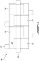
- a single rotary engine 100 is shown in Fig. 1 , it is understood that two or more rotary engines 100 can be provided with the rotors 114 thereof engaged to a same shaft to form a multi-rotor engine assembly.
- a rotary internal combustion engine 200 includes four rotors 114 each journaled on a respective eccentric portion of a common shaft 202. Each rotor 114 is received within a respective cavity 110 defining three rotating main combustion chambers 122 per rotor 114.
- each rotor 114 and cavity 100 is part of an engine 100 such as shown in Fig. 1 and described above.
- the engine assembly 200 includes a pilot subchamber 142 for each rotor 114, and each main chamber 122 communicates with the respective pilot subchamber 142 in a sequential manner. Although in the embodiment shown the engine 200 includes only four rotors 114, the engine 200 can include any other suitable number of rotors 114.
- the main fuel injection is delivered to one or more of the rotors 114 with a reduced main quantity as described above.
- the main quantity for this/these rotor(s) can include, for example, at most the pilot quantity injected in the pilot fuel injection and/or 10% of the maximum quantity of the main fuel injection when operating at maximum load; the main quantity can be zero or can be different from zero, as set forth above.
- the number of rotors for which the main quantity of the main injection has a value from 0 to the pilot quantity and/or 10% of the maximum quantity is varied, for example based on the power demand on the engine 200.
- the number "n" of rotors 114 (or main combustion chambers 122 receiving the ignited fuel from one of the pilot subchambers 142) in which the main quantity of the main injection has a value from 0 to the pilot quantity and/or 10% of the maximum quantity can be varied.
- main combustion chamber 122 receiving the ignited fuel is used herein to contrast with the other two main combustion chambers 122 of the rotor 114, which are in different phases of the combustion cycle and accordingly are not receiving ignited fuel at the time - the main combustion chamber 122 receiving the ignited fuel communicates with the main fuel injector during the combustion phase.
- the main combustion chamber 122 receiving the ignited fuel changes with the rotation of the rotor 114 and with every pilot fuel injection.
- the main injection of the main quantity having a value from 0 to the pilot quantity and/or 10% of the maximum quantity is delivered in "n" of the main combustion chambers 122 receiving ignited fuel, while the remaining "P-n" of the main combustion chambers 122 receiving ignited fuel receive a greater quantity of fuel in the main injection, for example the maximum quantity - with n being a whole number varying between 0 (maximum load) and P (all rotors 114 having a main fuel injection of the main quantity from 0 to the pilot quantity and/or 10% of the maximum quantity).
- Some or all of the remaining "P-n" main combustion chambers 122 can receive a main fuel injection of a quantity less than the maximum quantity, but more than the quantity injected into the "n" combustion chambers, e.g., more than 10% of the maximum quantity.
- the remaining "P-n" combustion chambers 122 receiving the ignited fuel may receive a main injection of 75% of the maximum quantity.
- Other quantities can alternately be used.
- the number n of the main combustion chambers 122 receiving ignited fuel in which the main fuel injection is delivered at the main quantity having a value from 0 to the pilot quantity and/or 10% of the maximum quantity varies incrementally, for example from 0 to P (reduction in load) or from P to 0 (increase in load).
- the number n of the main combustion chambers 122 receiving ignited fuel in which the main fuel injection is delivered at the main quantity having a value from 0 to the pilot quantity and/or 10% of the maximum quantity is delivered varies between 0 and 4, for example incrementally from 0 to 4 (reduction in load) or from 4 to 0 (increase in load).
- partial load conditions may be defined by a fixed number of the main combustion chambers 122 having the main fuel injection delivered at the main quantity having a value from 0 to the pilot quantity and/or 10% of the maximum quantity.
- delivering the main fuel injection of the main quantity having a value from 0 to the pilot quantity and/or 10% of the maximum quantity, in combination with a subchamber volume of at most 10% of the minimum combustion volume and a pilot fuel quantity of at most 10% of the maximum quantity of the main fuel injection at maximum load advantageously reduce the fuel consumption at idle and/or partial load conditions and allow the engine 100, 200 to operate at lean air-to-fuel mixtures, allowing for relatively low fuel consumption.
- a fuel consumption of about 0.04 pph of fuel per cubic inch of engine displacement (e.g., 2 pph for a single rotor engine with 50 cubic inches of displacement) (0.31 mg/s of fuel per cubic cm of engine displacement) can be obtained for the rotor(s) in which the main fuel injection is delivered at the main quantity having a value from 0 to the pilot quantity and/or 10% of the maximum quantity.
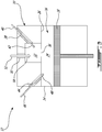
- a schematic illustration of a cylinder 10 of a reciprocating internal combustion engine 12 having a four-stroke cycle is shown.
- the cylinder 10 has an outer body 14 enclosing a variable volume combustion chamber 16 cooperating with a reciprocating piston 18 to undergo the four stroke phases of intake, compression, expansion and exhaust.
- the reciprocating motion of the piston 18 rotates a shaft (not shown), and multiple similar pistons are drivingly engaged to the same shaft, similarly to the embodiment shown in Fig.
- the outer body 14 has a pilot combustion subchamber 32 defined therein in communication with a main combustion chamber 34 defined within the outer body 14.
- the engine 12 includes a pilot subchamber 32 for each of the cylinders 10.
- the pilot subchamber 32 is sized similarly to the pilot subchamber 142 as described above.
- An elongated pilot injector hole 38 is defined through the outer body 14 in communication with the pilot subchamber 32.
- a pilot fuel injector 40 is received and retained within the corresponding hole 38, with a tip of the pilot injector 42 being received in the pilot subchamber 32.
- An elongated main injector hole 44 is defined through the outer body 14 in communication with the main chamber 34.
- a main fuel injector 46 is received and retained within the corresponding hole 44, with a tip of the main injector 48 communicating with the main chamber 34.
- the outer body 14 also has an ignition element elongated hole 50 defined therethrough in communication with the pilot subchamber 32.
- An ignition element 52 is received and retained within the corresponding hole 50, with a tip of the ignition element 54 being received in the pilot subchamber 32.
- the main fuel injection in the main combustion chamber 16 can be delivered with a reduced main quantity as described above for the engine 100; in addition, when multiple cylinders are provided, the number "n" of the main combustion chambers 16 in which the main fuel injection is delivered at the main quantity having a value from 0 to the pilot quantity and/or 10% of the maximum quantity can be varied, incrementally or otherwise, between 0 (maximum load conditions) and P, as described above for the engine 200.
Landscapes
- Engineering & Computer Science (AREA)
- Mechanical Engineering (AREA)
- General Engineering & Computer Science (AREA)
- Chemical & Material Sciences (AREA)
- Combustion & Propulsion (AREA)
- Combustion Methods Of Internal-Combustion Engines (AREA)
- Output Control And Ontrol Of Special Type Engine (AREA)
- Electrical Control Of Air Or Fuel Supplied To Internal-Combustion Engine (AREA)
Claims (13)
- Procédé de fonctionnement d'un moteur à combustion interne (100, 12, 200) ayant des sous-chambres pilotes (142, 32) communiquant avec des chambres de combustion principales (122, 16), le moteur à combustion interne (100, 12, 200) étant configuré en utilisation pour fournir une injection de carburant principale d'une quantité maximale de carburant aux chambres de combustion principales (122, 16) lorsque le moteur à combustion interne (100, 12, 200) fonctionne à charge maximale, le procédé comprenant :la fourniture d'une injection de carburant pilote d'une quantité pilote de carburant aux sous-chambres pilotes (142, 32), moyennant quoi la quantité pilote représente au maximum 10 % de la quantité maximale ;l'allumage de l'injection de carburant pilote à l'intérieur des sous-chambres pilotes (142, 32) ;la direction du carburant enflammé des sous-chambres pilotes (142, 32) vers les chambres de combustion principales (122, 16) ; etdans lequel le moteur à combustion interne (100, 12, 200) a un nombre P de sous-chambres pilotes (142, 32) communiquant avec les chambres de combustion principales (122, 16), le procédé comprenant en outre :pour un nombre n des chambres de combustion principales (122, 16) recevant le carburant enflammé, la fourniture d'une injection de carburant principale d'une première quantité principale de carburant, la première quantité principale représentant au maximum 10 % de la quantité maximale ;pour un nombre P-n des chambres de combustion principales (122, 16) recevant le carburant enflammé, la fourniture d'une injection de carburant principale d'une seconde quantité principale de carburant, la seconde quantité principale de carburant représentant plus de 10 % de la quantité maximale ; etla variation de n par incréments entre zéro et P ou la variation de n par incréments entre P et zéro.
- Procédé selon la revendication 1, comprenant en outre, pour au moins une autre des chambres de combustion principales (122, 16) recevant le carburant enflammé :la fourniture d'une injection de carburant principale de la quantité maximale de carburant, oula fourniture d'une injection de carburant principale de plus de 10 % de la quantité maximale.
- Procédé selon la revendication 1 ou 2, dans lequel le moteur à combustion interne (100) est un moteur rotatif incluant une pluralité de rotors (114) reçus chacun de manière étanche dans un logement (102) respectif pour définir les chambres de combustion principales (122), et chacune des sous-chambres pilotes (142) est en communication avec les chambres de combustion principales (122) d'un des rotors (114) respectifs de manière séquentielle.
- Procédé selon une quelconque revendication précédente, dans lequel la quantité principale est sélectionnée de sorte à maintenir une température de paroi des sous-chambres pilotes (142, 32) à une valeur de 500° F (260° C) à 1400° F (760° C).
- Procédé selon une quelconque revendication précédente, dans lequel chacune des chambres de combustion principales (122, 16) a un volume variant entre un volume de chambre minimal (Vmin) et un volume de chambre maximal (Vmax), et chacune des sous-chambres pilotes (142, 32) a un volume V2 de 10 % maximum d'une somme de V2 et du volume de chambre minimal (Vmin) .
- Procédé selon une quelconque revendication précédente, dans lequel la seconde quantité principale est la quantité maximale.
- Procédé selon une quelconque revendication précédente, dans lequel la première quantité principale est nulle.
- Procédé selon l'une quelconque des revendications 1 à 6, dans lequel la première quantité principale est au maximum la quantité pilote.
- Procédé de fonctionnement d'un moteur à combustion interne rotatif (100, 200) incluant un rotor (114) reçu de manière étanche dans un logement (102) pour définir une pluralité de chambres de combustion principales rotatives (122), le moteur à combustion interne rotatif (100, 200) étant configuré en utilisation pour fournir une injection de carburant principale d'une quantité maximale de carburant aux chambres de combustion principales (122) lorsque le moteur à combustion interne (100, 200) fonctionne à charge maximale, le procédé comprenant :la fourniture d'une injection de carburant pilote d'une quantité pilote de carburant à une sous-chambre pilote (142) ;l'allumage de l'injection de carburant pilote à l'intérieur de la sous-chambre pilote (142) ;la direction du carburant enflammé de la sous-chambre pilote (142) dans l'une des chambres de combustion principales (122) ; etla fourniture d'une injection de carburant principale d'une quantité principale de carburant à la chambre de combustion principale (122) recevant le carburant enflammé, caractérisé en ce quela quantité pilote représente au maximum 10 % de la quantité maximale ;dans lequel le moteur à combustion interne (100, 12, 200) a un nombre P de sous-chambres pilotes (142, 32) communiquant avec les chambres de combustion principales (122, 16), le procédé comprenant en outre :pour un nombre n des chambres de combustion principales (122, 16) recevant le carburant enflammé, la fourniture d'une injection de carburant principale d'une première quantité principale de carburant, la première quantité principale représentant au maximum 10 % de la quantité maximale ;pour un nombre P-n des chambres de combustion principales (122, 16) recevant le carburant enflammé, la fourniture d'une injection de carburant principale d'une seconde quantité principale de carburant, la seconde quantité principale de carburant représentant plus de 10 % de la quantité maximale ; etla variation de n par incréments entre zéro et P ou la variation de n par incréments entre P et zéro.
- Procédé selon la revendication 9, dans lequel chacune des chambres de combustion principales (122) a un volume variant entre un volume de chambre minimal (Vmin) et un volume de chambre maximal (Vmax), et chacune des sous-chambres pilotes (142, 32) a un volume V2 de 10 % maximum d'une somme de V2 et du volume de chambre minimum (Vmin) .
- Procédé selon les revendications 9 ou 10, comprenant en outre, après fourniture de l'injection de carburant principale avec la quantité principale étant au maximum 10 % de la quantité maximale, l'augmentation de la quantité principale à la quantité maximale.
- Procédé selon une quelconque revendication précédente, dans lequel la quantité principale est nulle.
- Procédé selon l'une quelconque des revendications 1 à 11, dans lequel la quantité principale est au maximum la quantité pilote.
Priority Applications (1)
| Application Number | Priority Date | Filing Date | Title |
|---|---|---|---|
| PL17192456T PL3299607T3 (pl) | 2016-09-23 | 2017-09-21 | Sposób działania silnika z pilotującą komorą podrzędną w warunkach obciążenia częściowego |
Applications Claiming Priority (1)
| Application Number | Priority Date | Filing Date | Title |
|---|---|---|---|
| US15/273,788 US10072559B2 (en) | 2016-09-23 | 2016-09-23 | Method of operating an engine having a pilot subchamber at partial load conditions |
Publications (2)
| Publication Number | Publication Date |
|---|---|
| EP3299607A1 EP3299607A1 (fr) | 2018-03-28 |
| EP3299607B1 true EP3299607B1 (fr) | 2020-04-15 |
Family
ID=59982269
Family Applications (1)
| Application Number | Title | Priority Date | Filing Date |
|---|---|---|---|
| EP17192456.6A Active EP3299607B1 (fr) | 2016-09-23 | 2017-09-21 | Procédé de fonctionnement d'un moteur ayant une sous-chambre pilote dans des conditions de charge partielle |
Country Status (6)
| Country | Link |
|---|---|
| US (2) | US10072559B2 (fr) |
| EP (1) | EP3299607B1 (fr) |
| CA (1) | CA2978592A1 (fr) |
| ES (1) | ES2797956T3 (fr) |
| PL (1) | PL3299607T3 (fr) |
| WO (1) | WO2018053622A1 (fr) |
Families Citing this family (7)
| Publication number | Priority date | Publication date | Assignee | Title |
|---|---|---|---|---|
| US9038594B2 (en) | 2011-07-28 | 2015-05-26 | Pratt & Whitney Canada Corp. | Rotary internal combustion engine with pilot subchamber |
| US9528434B1 (en) | 2011-07-28 | 2016-12-27 | Pratt & Whitney Canada Corp. | Rotary internal combustion engine with pilot subchamber |
| US10557407B2 (en) | 2011-07-28 | 2020-02-11 | Pratt & Whitney Canada Corp. | Rotary internal combustion engine with pilot subchamber |
| US10072559B2 (en) * | 2016-09-23 | 2018-09-11 | Pratt & Whitney Canada Corp. | Method of operating an engine having a pilot subchamber at partial load conditions |
| US10711729B2 (en) * | 2017-07-19 | 2020-07-14 | Ford Global Technologies, Llc | Diesel engine dual fuel injection strategy |
| US11408329B2 (en) * | 2019-12-19 | 2022-08-09 | Board Of Trustees Of Michigan State University | Engine turbulent jet ignition system |
| EP4290061A1 (fr) * | 2022-06-06 | 2023-12-13 | Volvo Construction Equipment AB | Système et procédé d'injection de carburant |
Family Cites Families (32)
| Publication number | Priority date | Publication date | Assignee | Title |
|---|---|---|---|---|
| US4060058A (en) | 1975-11-28 | 1977-11-29 | Ford Motor Company | Internal combustion engine control system |
| US4259932A (en) * | 1976-05-26 | 1981-04-07 | Ford Motor Company | Internal combustion engine control system |
| DE2841522A1 (de) | 1978-09-23 | 1980-04-03 | Porsche Ag | Gemischverdichtende fremdgezuendete viertakt-brennkraftmaschine mit ladungsschichtung |
| US4239023A (en) * | 1978-12-07 | 1980-12-16 | Ford Motor Company | Fuel injection system for dual combustion chamber engine |
| FR2460392A1 (fr) | 1979-06-29 | 1981-01-23 | Volzh Ob Proizv | Procede d'amenagement d'un moteur a combustion interne a plusieurs compartiments et pistons rotatifs et dispositif en comportant application |
| US4594976A (en) | 1985-03-18 | 1986-06-17 | The Cessna Aircraft Company | Hybrid internal combustion reciprocating engine |
| US4765293A (en) * | 1986-05-07 | 1988-08-23 | The Cessna Aircraft Company | Hybrid internal combustion reciprocating engine |
| US4831993A (en) * | 1987-12-28 | 1989-05-23 | Erik Kelgard | Method of operating carburetted dual-fuel engines with diesel pilot oil injection |
| JPH0237115A (ja) | 1988-07-25 | 1990-02-07 | Mazda Motor Corp | 燃料噴射式エンジン |
| US5271357A (en) * | 1992-01-24 | 1993-12-21 | General Electric Company | Method of combustion for dual fuel engine |
| DE19621297C1 (de) * | 1996-05-28 | 1997-12-04 | Man B & W Diesel Ag | Einrichtung zur Steuerung/Regelung der Zündöl-Einspritzung eines Gasmotors |
| US6202601B1 (en) * | 2000-02-11 | 2001-03-20 | Westport Research Inc. | Method and apparatus for dual fuel injection into an internal combustion engine |
| WO2004074655A1 (fr) | 2003-02-24 | 2004-09-02 | Pratt & Whitney Canada Corp. | Moteur rotatif turbo-combine integre a faible taux de compression volumetrique |
| DE102004006294B3 (de) * | 2004-02-09 | 2005-10-13 | Siemens Ag | Verfahren zur Gleichstellung der Einspritzmengenunterschiede zwischen den Zylindern einer Brennkraftmaschine |
| US7243862B2 (en) * | 2004-04-07 | 2007-07-17 | Delphi Technologies, Inc. | Apparatus and method for mode-switching fuel injector nozzle |
| DE102004023409B4 (de) * | 2004-05-12 | 2007-05-16 | Gottfried Schubert | Hochverdichtender Ottoverbrennungsmotor mit Drosselregelung, Fremdzündung und Kraftstoffdirekteinspritzung in eine Vorbrennkammer |
| US7484405B2 (en) * | 2007-04-26 | 2009-02-03 | Gm Global Technology Operations, Inc. | System and method for engine sound calibration |
| JP4315218B2 (ja) * | 2007-06-12 | 2009-08-19 | トヨタ自動車株式会社 | 燃料噴射制御装置 |
| US7753036B2 (en) | 2007-07-02 | 2010-07-13 | United Technologies Corporation | Compound cycle rotary engine |
| JP4404111B2 (ja) * | 2007-07-19 | 2010-01-27 | トヨタ自動車株式会社 | 内燃機関の燃料噴射制御装置 |
| DE102008000552A1 (de) * | 2008-03-07 | 2009-09-10 | Robert Bosch Gmbh | Verfahren zum Betreiben eines selbstzündenden Verbrennungsmotors und entsprechende Steuervorrichtung |
| US20120191325A1 (en) * | 2010-01-13 | 2012-07-26 | GM Global Technology Operations LLC | Injection fuel and load balancing control system |
| JP5730679B2 (ja) | 2011-06-16 | 2015-06-10 | ヤンマー株式会社 | エンジン装置 |
| US9038594B2 (en) | 2011-07-28 | 2015-05-26 | Pratt & Whitney Canada Corp. | Rotary internal combustion engine with pilot subchamber |
| US10557407B2 (en) * | 2011-07-28 | 2020-02-11 | Pratt & Whitney Canada Corp. | Rotary internal combustion engine with pilot subchamber |
| CA2798599C (fr) * | 2012-12-14 | 2013-11-12 | Westport Power Inc. | Systeme d'injection a ouverture variable des soupapes et sa methode |
| US9255543B2 (en) * | 2012-12-14 | 2016-02-09 | Hyundai Motor Company | Fuel injection amount compensating method |
| US10280830B2 (en) | 2013-03-08 | 2019-05-07 | Pratt & Whitney Canada Corp. | System for pilot subchamber temperature control |
| US9200563B2 (en) | 2013-03-12 | 2015-12-01 | Pratt & Whitney Canada Corp. | Internal combustion engine with common rail pilot and main injection |
| KR20180017181A (ko) | 2015-06-17 | 2018-02-20 | 바르실라 핀랜드 오이 | 멀티-실린더 피스톤 엔진을 작동시키기 위한 방법 및 피스톤 엔진 |
| US10041402B2 (en) * | 2016-05-12 | 2018-08-07 | Pratt & Whitney Canada Corp. | Internal combustion engine with split pilot injection |
| US10072559B2 (en) * | 2016-09-23 | 2018-09-11 | Pratt & Whitney Canada Corp. | Method of operating an engine having a pilot subchamber at partial load conditions |
-
2016
- 2016-09-23 US US15/273,788 patent/US10072559B2/en active Active
-
2017
- 2017-09-06 CA CA2978592A patent/CA2978592A1/fr active Pending
- 2017-09-07 WO PCT/CA2017/051049 patent/WO2018053622A1/fr active Application Filing
- 2017-09-21 ES ES17192456T patent/ES2797956T3/es active Active
- 2017-09-21 PL PL17192456T patent/PL3299607T3/pl unknown
- 2017-09-21 EP EP17192456.6A patent/EP3299607B1/fr active Active
-
2018
- 2018-08-10 US US16/100,611 patent/US10533486B2/en active Active
Non-Patent Citations (1)
| Title |
|---|
| None * |
Also Published As
| Publication number | Publication date |
|---|---|
| WO2018053622A1 (fr) | 2018-03-29 |
| US20180347450A1 (en) | 2018-12-06 |
| PL3299607T3 (pl) | 2020-12-14 |
| US20180087446A1 (en) | 2018-03-29 |
| CA2978592A1 (fr) | 2018-03-23 |
| US10533486B2 (en) | 2020-01-14 |
| EP3299607A1 (fr) | 2018-03-28 |
| ES2797956T3 (es) | 2020-12-04 |
| US10072559B2 (en) | 2018-09-11 |
Similar Documents
| Publication | Publication Date | Title |
|---|---|---|
| US10697365B2 (en) | Rotary internal combustion engine with pilot subchamber | |
| US10267217B2 (en) | Internal combustion engine with common rail injection | |
| EP3299607B1 (fr) | Procédé de fonctionnement d'un moteur ayant une sous-chambre pilote dans des conditions de charge partielle | |
| EP2778367B1 (fr) | Moteur à combustion interne à injection pilote et principale | |
| US11306651B2 (en) | Method of operating an internal combustion engine | |
| US11261781B2 (en) | Rotary internal combustion engine with unequal volumetric ratios | |
| EP3351763B1 (fr) | Procédé de fonctionnement d'un moteur rotatif |
Legal Events
| Date | Code | Title | Description |
|---|---|---|---|
| PUAI | Public reference made under article 153(3) epc to a published international application that has entered the european phase |
Free format text: ORIGINAL CODE: 0009012 |
|
| STAA | Information on the status of an ep patent application or granted ep patent |
Free format text: STATUS: THE APPLICATION HAS BEEN PUBLISHED |
|
| AK | Designated contracting states |
Kind code of ref document: A1 Designated state(s): AL AT BE BG CH CY CZ DE DK EE ES FI FR GB GR HR HU IE IS IT LI LT LU LV MC MK MT NL NO PL PT RO RS SE SI SK SM TR |
|
| AX | Request for extension of the european patent |
Extension state: BA ME |
|
| STAA | Information on the status of an ep patent application or granted ep patent |
Free format text: STATUS: REQUEST FOR EXAMINATION WAS MADE |
|
| 17P | Request for examination filed |
Effective date: 20180928 |
|
| RBV | Designated contracting states (corrected) |
Designated state(s): AL AT BE BG CH CY CZ DE DK EE ES FI FR GB GR HR HU IE IS IT LI LT LU LV MC MK MT NL NO PL PT RO RS SE SI SK SM TR |
|
| STAA | Information on the status of an ep patent application or granted ep patent |
Free format text: STATUS: EXAMINATION IS IN PROGRESS |
|
| 17Q | First examination report despatched |
Effective date: 20181130 |
|
| GRAP | Despatch of communication of intention to grant a patent |
Free format text: ORIGINAL CODE: EPIDOSNIGR1 |
|
| STAA | Information on the status of an ep patent application or granted ep patent |
Free format text: STATUS: GRANT OF PATENT IS INTENDED |
|
| INTG | Intention to grant announced |
Effective date: 20190814 |
|
| GRAJ | Information related to disapproval of communication of intention to grant by the applicant or resumption of examination proceedings by the epo deleted |
Free format text: ORIGINAL CODE: EPIDOSDIGR1 |
|
| STAA | Information on the status of an ep patent application or granted ep patent |
Free format text: STATUS: EXAMINATION IS IN PROGRESS |
|
| GRAP | Despatch of communication of intention to grant a patent |
Free format text: ORIGINAL CODE: EPIDOSNIGR1 |
|
| STAA | Information on the status of an ep patent application or granted ep patent |
Free format text: STATUS: GRANT OF PATENT IS INTENDED |
|
| INTG | Intention to grant announced |
Effective date: 20191121 |
|
| GRAS | Grant fee paid |
Free format text: ORIGINAL CODE: EPIDOSNIGR3 |
|
| GRAA | (expected) grant |
Free format text: ORIGINAL CODE: 0009210 |
|
| STAA | Information on the status of an ep patent application or granted ep patent |
Free format text: STATUS: THE PATENT HAS BEEN GRANTED |
|
| AK | Designated contracting states |
Kind code of ref document: B1 Designated state(s): AL AT BE BG CH CY CZ DE DK EE ES FI FR GB GR HR HU IE IS IT LI LT LU LV MC MK MT NL NO PL PT RO RS SE SI SK SM TR |
|
| REG | Reference to a national code |
Ref country code: CH Ref legal event code: EP |
|
| REG | Reference to a national code |
Ref country code: DE Ref legal event code: R096 Ref document number: 602017014700 Country of ref document: DE |
|
| REG | Reference to a national code |
Ref country code: IE Ref legal event code: FG4D |
|
| REG | Reference to a national code |
Ref country code: CH Ref legal event code: NV Representative=s name: VALIPAT S.A. C/O BOVARD SA NEUCHATEL, CH Ref country code: AT Ref legal event code: REF Ref document number: 1257569 Country of ref document: AT Kind code of ref document: T Effective date: 20200515 |
|
| REG | Reference to a national code |
Ref country code: NL Ref legal event code: MP Effective date: 20200415 |
|
| REG | Reference to a national code |
Ref country code: LT Ref legal event code: MG4D |
|
| PG25 | Lapsed in a contracting state [announced via postgrant information from national office to epo] |
Ref country code: LT Free format text: LAPSE BECAUSE OF FAILURE TO SUBMIT A TRANSLATION OF THE DESCRIPTION OR TO PAY THE FEE WITHIN THE PRESCRIBED TIME-LIMIT Effective date: 20200415 Ref country code: PT Free format text: LAPSE BECAUSE OF FAILURE TO SUBMIT A TRANSLATION OF THE DESCRIPTION OR TO PAY THE FEE WITHIN THE PRESCRIBED TIME-LIMIT Effective date: 20200817 Ref country code: GR Free format text: LAPSE BECAUSE OF FAILURE TO SUBMIT A TRANSLATION OF THE DESCRIPTION OR TO PAY THE FEE WITHIN THE PRESCRIBED TIME-LIMIT Effective date: 20200716 Ref country code: NO Free format text: LAPSE BECAUSE OF FAILURE TO SUBMIT A TRANSLATION OF THE DESCRIPTION OR TO PAY THE FEE WITHIN THE PRESCRIBED TIME-LIMIT Effective date: 20200715 Ref country code: NL Free format text: LAPSE BECAUSE OF FAILURE TO SUBMIT A TRANSLATION OF THE DESCRIPTION OR TO PAY THE FEE WITHIN THE PRESCRIBED TIME-LIMIT Effective date: 20200415 Ref country code: IS Free format text: LAPSE BECAUSE OF FAILURE TO SUBMIT A TRANSLATION OF THE DESCRIPTION OR TO PAY THE FEE WITHIN THE PRESCRIBED TIME-LIMIT Effective date: 20200815 Ref country code: SE Free format text: LAPSE BECAUSE OF FAILURE TO SUBMIT A TRANSLATION OF THE DESCRIPTION OR TO PAY THE FEE WITHIN THE PRESCRIBED TIME-LIMIT Effective date: 20200415 Ref country code: FI Free format text: LAPSE BECAUSE OF FAILURE TO SUBMIT A TRANSLATION OF THE DESCRIPTION OR TO PAY THE FEE WITHIN THE PRESCRIBED TIME-LIMIT Effective date: 20200415 |
|
| PG25 | Lapsed in a contracting state [announced via postgrant information from national office to epo] |
Ref country code: HR Free format text: LAPSE BECAUSE OF FAILURE TO SUBMIT A TRANSLATION OF THE DESCRIPTION OR TO PAY THE FEE WITHIN THE PRESCRIBED TIME-LIMIT Effective date: 20200415 Ref country code: LV Free format text: LAPSE BECAUSE OF FAILURE TO SUBMIT A TRANSLATION OF THE DESCRIPTION OR TO PAY THE FEE WITHIN THE PRESCRIBED TIME-LIMIT Effective date: 20200415 Ref country code: BG Free format text: LAPSE BECAUSE OF FAILURE TO SUBMIT A TRANSLATION OF THE DESCRIPTION OR TO PAY THE FEE WITHIN THE PRESCRIBED TIME-LIMIT Effective date: 20200715 Ref country code: RS Free format text: LAPSE BECAUSE OF FAILURE TO SUBMIT A TRANSLATION OF THE DESCRIPTION OR TO PAY THE FEE WITHIN THE PRESCRIBED TIME-LIMIT Effective date: 20200415 |
|
| REG | Reference to a national code |
Ref country code: ES Ref legal event code: FG2A Ref document number: 2797956 Country of ref document: ES Kind code of ref document: T3 Effective date: 20201204 |
|
| PG25 | Lapsed in a contracting state [announced via postgrant information from national office to epo] |
Ref country code: AL Free format text: LAPSE BECAUSE OF FAILURE TO SUBMIT A TRANSLATION OF THE DESCRIPTION OR TO PAY THE FEE WITHIN THE PRESCRIBED TIME-LIMIT Effective date: 20200415 |
|
| REG | Reference to a national code |
Ref country code: DE Ref legal event code: R097 Ref document number: 602017014700 Country of ref document: DE |
|
| PG25 | Lapsed in a contracting state [announced via postgrant information from national office to epo] |
Ref country code: RO Free format text: LAPSE BECAUSE OF FAILURE TO SUBMIT A TRANSLATION OF THE DESCRIPTION OR TO PAY THE FEE WITHIN THE PRESCRIBED TIME-LIMIT Effective date: 20200415 Ref country code: EE Free format text: LAPSE BECAUSE OF FAILURE TO SUBMIT A TRANSLATION OF THE DESCRIPTION OR TO PAY THE FEE WITHIN THE PRESCRIBED TIME-LIMIT Effective date: 20200415 Ref country code: SM Free format text: LAPSE BECAUSE OF FAILURE TO SUBMIT A TRANSLATION OF THE DESCRIPTION OR TO PAY THE FEE WITHIN THE PRESCRIBED TIME-LIMIT Effective date: 20200415 Ref country code: DK Free format text: LAPSE BECAUSE OF FAILURE TO SUBMIT A TRANSLATION OF THE DESCRIPTION OR TO PAY THE FEE WITHIN THE PRESCRIBED TIME-LIMIT Effective date: 20200415 |
|
| PLBE | No opposition filed within time limit |
Free format text: ORIGINAL CODE: 0009261 |
|
| STAA | Information on the status of an ep patent application or granted ep patent |
Free format text: STATUS: NO OPPOSITION FILED WITHIN TIME LIMIT |
|
| PG25 | Lapsed in a contracting state [announced via postgrant information from national office to epo] |
Ref country code: SK Free format text: LAPSE BECAUSE OF FAILURE TO SUBMIT A TRANSLATION OF THE DESCRIPTION OR TO PAY THE FEE WITHIN THE PRESCRIBED TIME-LIMIT Effective date: 20200415 |
|
| 26N | No opposition filed |
Effective date: 20210118 |
|
| PG25 | Lapsed in a contracting state [announced via postgrant information from national office to epo] |
Ref country code: SI Free format text: LAPSE BECAUSE OF FAILURE TO SUBMIT A TRANSLATION OF THE DESCRIPTION OR TO PAY THE FEE WITHIN THE PRESCRIBED TIME-LIMIT Effective date: 20200415 |
|
| REG | Reference to a national code |
Ref country code: BE Ref legal event code: MM Effective date: 20200930 |
|
| PG25 | Lapsed in a contracting state [announced via postgrant information from national office to epo] |
Ref country code: LU Free format text: LAPSE BECAUSE OF NON-PAYMENT OF DUE FEES Effective date: 20200921 |
|
| PG25 | Lapsed in a contracting state [announced via postgrant information from national office to epo] |
Ref country code: BE Free format text: LAPSE BECAUSE OF NON-PAYMENT OF DUE FEES Effective date: 20200930 Ref country code: IE Free format text: LAPSE BECAUSE OF NON-PAYMENT OF DUE FEES Effective date: 20200921 |
|
| PG25 | Lapsed in a contracting state [announced via postgrant information from national office to epo] |
Ref country code: TR Free format text: LAPSE BECAUSE OF FAILURE TO SUBMIT A TRANSLATION OF THE DESCRIPTION OR TO PAY THE FEE WITHIN THE PRESCRIBED TIME-LIMIT Effective date: 20200415 Ref country code: MT Free format text: LAPSE BECAUSE OF FAILURE TO SUBMIT A TRANSLATION OF THE DESCRIPTION OR TO PAY THE FEE WITHIN THE PRESCRIBED TIME-LIMIT Effective date: 20200415 Ref country code: CY Free format text: LAPSE BECAUSE OF FAILURE TO SUBMIT A TRANSLATION OF THE DESCRIPTION OR TO PAY THE FEE WITHIN THE PRESCRIBED TIME-LIMIT Effective date: 20200415 |
|
| PG25 | Lapsed in a contracting state [announced via postgrant information from national office to epo] |
Ref country code: MK Free format text: LAPSE BECAUSE OF FAILURE TO SUBMIT A TRANSLATION OF THE DESCRIPTION OR TO PAY THE FEE WITHIN THE PRESCRIBED TIME-LIMIT Effective date: 20200415 Ref country code: MC Free format text: LAPSE BECAUSE OF FAILURE TO SUBMIT A TRANSLATION OF THE DESCRIPTION OR TO PAY THE FEE WITHIN THE PRESCRIBED TIME-LIMIT Effective date: 20200415 |
|
| REG | Reference to a national code |
Ref country code: AT Ref legal event code: UEP Ref document number: 1257569 Country of ref document: AT Kind code of ref document: T Effective date: 20200415 |
|
| P01 | Opt-out of the competence of the unified patent court (upc) registered |
Effective date: 20230530 |
|
| PGFP | Annual fee paid to national office [announced via postgrant information from national office to epo] |
Ref country code: IT Payment date: 20230822 Year of fee payment: 7 Ref country code: CZ Payment date: 20230825 Year of fee payment: 7 Ref country code: AT Payment date: 20230823 Year of fee payment: 7 |
|
| PGFP | Annual fee paid to national office [announced via postgrant information from national office to epo] |
Ref country code: PL Payment date: 20230823 Year of fee payment: 7 |
|
| PGFP | Annual fee paid to national office [announced via postgrant information from national office to epo] |
Ref country code: ES Payment date: 20231002 Year of fee payment: 7 |
|
| PGFP | Annual fee paid to national office [announced via postgrant information from national office to epo] |
Ref country code: CH Payment date: 20231001 Year of fee payment: 7 |
|
| PGFP | Annual fee paid to national office [announced via postgrant information from national office to epo] |
Ref country code: DE Payment date: 20240820 Year of fee payment: 8 |
|
| PGFP | Annual fee paid to national office [announced via postgrant information from national office to epo] |
Ref country code: GB Payment date: 20240822 Year of fee payment: 8 |
|
| PGFP | Annual fee paid to national office [announced via postgrant information from national office to epo] |
Ref country code: FR Payment date: 20240820 Year of fee payment: 8 |