EP3299602B1 - Verbindung für ein abgasumgehungsventil eines mehrstufigen turboladers - Google Patents
Verbindung für ein abgasumgehungsventil eines mehrstufigen turboladers Download PDFInfo
- Publication number
- EP3299602B1 EP3299602B1 EP17191498.9A EP17191498A EP3299602B1 EP 3299602 B1 EP3299602 B1 EP 3299602B1 EP 17191498 A EP17191498 A EP 17191498A EP 3299602 B1 EP3299602 B1 EP 3299602B1
- Authority
- EP
- European Patent Office
- Prior art keywords
- spring
- linkage
- assembly
- housing
- exhaust
- Prior art date
- Legal status (The legal status is an assumption and is not a legal conclusion. Google has not performed a legal analysis and makes no representation as to the accuracy of the status listed.)
- Active
Links
Images






Classifications
-
- F—MECHANICAL ENGINEERING; LIGHTING; HEATING; WEAPONS; BLASTING
- F02—COMBUSTION ENGINES; HOT-GAS OR COMBUSTION-PRODUCT ENGINE PLANTS
- F02B—INTERNAL-COMBUSTION PISTON ENGINES; COMBUSTION ENGINES IN GENERAL
- F02B37/00—Engines characterised by provision of pumps driven at least for part of the time by exhaust
- F02B37/12—Control of the pumps
- F02B37/18—Control of the pumps by bypassing exhaust from the inlet to the outlet of turbine or to the atmosphere
- F02B37/183—Arrangements of bypass valves or actuators therefor
- F02B37/186—Arrangements of actuators or linkage for bypass valves
-
- F—MECHANICAL ENGINEERING; LIGHTING; HEATING; WEAPONS; BLASTING
- F02—COMBUSTION ENGINES; HOT-GAS OR COMBUSTION-PRODUCT ENGINE PLANTS
- F02B—INTERNAL-COMBUSTION PISTON ENGINES; COMBUSTION ENGINES IN GENERAL
- F02B37/00—Engines characterised by provision of pumps driven at least for part of the time by exhaust
- F02B37/004—Engines characterised by provision of pumps driven at least for part of the time by exhaust with exhaust drives arranged in series
-
- F—MECHANICAL ENGINEERING; LIGHTING; HEATING; WEAPONS; BLASTING
- F02—COMBUSTION ENGINES; HOT-GAS OR COMBUSTION-PRODUCT ENGINE PLANTS
- F02B—INTERNAL-COMBUSTION PISTON ENGINES; COMBUSTION ENGINES IN GENERAL
- F02B37/00—Engines characterised by provision of pumps driven at least for part of the time by exhaust
- F02B37/013—Engines characterised by provision of pumps driven at least for part of the time by exhaust with exhaust-driven pumps arranged in series
-
- Y—GENERAL TAGGING OF NEW TECHNOLOGICAL DEVELOPMENTS; GENERAL TAGGING OF CROSS-SECTIONAL TECHNOLOGIES SPANNING OVER SEVERAL SECTIONS OF THE IPC; TECHNICAL SUBJECTS COVERED BY FORMER USPC CROSS-REFERENCE ART COLLECTIONS [XRACs] AND DIGESTS
- Y02—TECHNOLOGIES OR APPLICATIONS FOR MITIGATION OR ADAPTATION AGAINST CLIMATE CHANGE
- Y02T—CLIMATE CHANGE MITIGATION TECHNOLOGIES RELATED TO TRANSPORTATION
- Y02T10/00—Road transport of goods or passengers
- Y02T10/10—Internal combustion engine [ICE] based vehicles
- Y02T10/12—Improving ICE efficiencies
Definitions
- An exhaust bypass valve is often used to control operation of serial turbocharger systems. Such a valve may be operated to physically divert exhaust or alter pressures in exhaust pathways, for example, to direct exhaust flow partially or fully to one of multiple turbines in a system.
- a typical exhaust bypass valve experiences high exhaust pressure on one side and lower pressure on the other side.
- pressure differentials may challenge one or more inter-component seals and result in detrimental exhaust leakage.
- Patent publication EP2530275 A2 shows a serial turbocharger system with a seal mechanism for an exhaust bypass valve.
- each of the turbochargers 120-1 and 120-2 can act to extract energy from the exhaust and to provide energy to intake air, which may be combined with fuel to form combustion gas.
- each of the turbochargers 120-1 and 120-2 includes a shaft 122-1 and 122-2, a compressor 124-1 and 124-2, and a turbine 126-1 and 126-2.
- Each of the turbochargers 120-1 and 120-2 may include a housing, which may be referred to as a center housing (e.g., disposed between a respective compressor and turbine).
- a turbocharger shaft may be a shaft assembly that includes a variety of components.
- the turbochargers 120-1 and 120-2 are operated in series, sequentially. Specifically, exhaust from the exhaust manifold 116 is directed first to the turbine 126-1, which causes rotation of the compressor 124-1, and then to the turbine 126-2, which causes rotation of the compressor 124-2. As the turbine 126-1 extracts energy from the exhaust, the exhaust pressure decreases while the compressor 124-1 increases boost pressure (e.g., pressure differential between its inlet and outlet).
- boost pressure e.g., pressure differential between its inlet and outlet.
- the turbocharger 120-1 is referred to as a high pressure turbocharger while the turbocharger 120-2 is referred to as a low pressure turbocharger for the serial sequential operational state. As indicated in Fig.
- an air valve 115 may be configured in an orientation that directs compressed air from the compressor 124-2 to the inlet of the compressor 124-1 and an exhaust valve 125 may be configured in an orientation that directs exhaust from the manifold 116 to the turbine 126-1.
- either or both of the valves 115 and 125 may be regulated.
- the valve 115 may be regulated such that at least some intake air bypasses the compressor 124-1 and the valve 125 may be regulated such that at least some exhaust bypasses the turbine 126-1. Such regulation may occur while the system 100 is maintained in a serial sequential operational state.
- the system 100 operates fully or essentially as a single turbocharger system. Such an operational state is typically selected for high engine RPM.
- regulation of the exhaust valve 125 can act to pilot the low pressure turbocharger 120-2.
- a controller may actuate the exhaust valve 125 to increase flow of exhaust to the turbine 126-2 (e.g., via physical diversion or pressure differential).
- the increased flow to the turbine 126-2 increases rotational speed of the shaft 122-2, which prepares the turbocharger 120-2 for a more rapid response and power output (e.g., with minimum turbo lag) upon configuration of the exhaust valve 125 in an orientation that causes full or significant bypass of the turbine 126-1.
- the system 100 may also include other features, for example, a heat exchanger (e.g., or heat exchangers) may be positioned to cool compressed intake air prior to delivery of the compressed air to the combustion chambers of the engine 110.
- a heat exchanger may include a water-cooled compressor housing.
- the system 100 may include one or more exhaust gas recirculation paths that can circulate exhaust to intake air; noting that exhaust valves and intake valves for combustion chambers of the engine 110 may be appropriately controlled to achieve some degree of exhaust "recirculation" (e.g., retention in a chamber).
- a controller 190 is shown as including one or more processors 192, memory 194 and one or more interfaces 196.
- a controller may include circuitry such as circuitry of an engine control unit.
- Such a controller may include circuitry that provides for reading, writing or reading and writing information (e.g., executable instructions, control instructions, data, etc.) to memory (e.g., a computer-readable storage medium).
- various methods or techniques may optionally be implemented in conjunction with a controller, for example, through control logic. Control logic may depend on one or more engine operating conditions.
- sensors may transmit information to the controller 190 via the one or more interfaces 196.
- Control logic may rely on such information and, in turn, the controller 190 may output control signals to control engine operation.
- the controller 190 may be configured to control an air valve (see, e.g., the air valve 115), an exhaust valve (see, e.g., the exhaust valve 125), a variable geometry assembly, a wastegate (see, e.g., the wastegate 135), an electric motor, or one or more other components associated with an engine, an exhaust turbine (or exhaust turbines), a turbocharger (or turbochargers), etc.
- the controller 190 may be configured to act as an actuator or to transmit a signal to an actuator configured to actuate, for example, the air valve 115, the exhaust valve 125, the wastegate valve 135 (e.g., to close or open a wastegate), etc.
- Figs. 2 and 3 show perspective views of a system 200 with two turbochargers 220-1 and 220-2 along with an air outlet 213, an air valve 215, an exhaust manifold 216, an exhaust valve 225, a wastegate 235, an air intake 234, an exhaust outlet 236, an air valve actuator 291, a wastegate actuator 293 and an exhaust valve actuator 295.
- Open headed arrows indicate intended air flow directions while solid headed arrows indicate intended exhaust flow directions.
- Each of the turbochargers 220-1 and 220-2 includes a compressor 224-1 and 224-2 and a turbine 226-1 and 226-2.
- an exhaust valve may be located in a variety of positions depending on number, shape and size of exhaust conduits.
- an exhaust valve acts to cause flow of exhaust predominantly to a larger of the turbochargers, which is often referred to as a low pressure turbocharger in a serial sequential arrangement.
- an exhaust valve may act to physically bypass a smaller, high pressure turbocharger or it may act to alter pressure in pathways.
- the exhaust valve 225 may be located adjacent the exhaust manifold 216 such that upon opening of the valve 225, exhaust flows along a lower pressure pathway to the larger turbine 226-2 of the low pressure turbocharger 220-2.
- the exhaust valve 225 can regulate exhaust flow form a high pressure source (e.g., manifold) to a lower pressure pathway.
- the housing 410 defines a chamber 414 configured for receipt of exhaust, in part, responsive to position of a poppet 420 (e.g., a valve or valve plug), which is attached to and movable by an arm 422, where the arm 422 may be attached to or linked to an actuator (see, e.g., actuator assembly 405).
- a poppet can act as a plug, for example, to plug or seal an opening (e.g., to plug or seal an opening to an exhaust manifold coupled to an internal combustion engine).
- the assembly 400 includes a valve seat 430 disposed between the housing 410 and another component 450, which may be a part of a manifold, attached to a manifold, etc.
- the valve seat 430 includes a base portion 432 and a wall portion 434 that extends axially away from the base portion 432 (e.g., as a pipe, cylindrical wall, etc.). Where the base portion 432 and the wall portion 434 include substantially circular cross-sections, the base portion 432 can include an outer diameter that exceeds an outer diameter of the wall portion 434.
- An exhaust passage is defined by an inner surface of the valve seat 430, which may be a substantially cylindrical surface.
- a lower surface of the poppet 420 may be about parallel to the interface between the housing 410 and the component 450 (e.g., and about parallel to a plane of a gasket or gaskets disposed between the housing 410 and the component 450).
- an angle may be considered in a force diagram, for example, to consider force applied to a valve seat by a poppet and balance of that force (e.g., as to one or more components that are in directly or indirectly in contact with the valve seat).
- the housing 510 includes a recess 513, a face 516 and a recess 517 as well as an edge 515 that defines an opening for flow of exhaust (e.g., from an outlet of a high pressure turbine).
- the gasket 560 is seated on the valve seat 530, which is received by the recess 513 of the housing 510, and the gasket 570 is seated in the recess 517 of the housing 510.
- the gasket 560 may include a V-shaped cross-section formed by a single piece or multiple pieces where the V-shaped cross-section is open about an inner perimeter and closed about an outer perimeter.
- a closed side of a V-shaped cross-section of the gasket 560 may be formed by a joint between two pieces such as an upper piece and a lower piece.
- the joint may be formed upon application of clamping force (e.g., by joining two components with the two pieces of the gasket therebetween) or, for example, the joint may be formed by welding or other process to join two pieces (e.g., in a manner where a seal is formed therebetween).
- an electric actuator can be utilized; however, an electrical actuator may be less desirable as to high, continuous load operating conditions due to the resistive heating of actuator motor coils, which can limit available peak, continuous force.
- an electrical actuator may be less desirable as to high, continuous load operating conditions due to the resistive heating of actuator motor coils, which can limit available peak, continuous force.
- relatively large vacuum pneumatic actuators these require a vacuum source (e.g., engine mounted vacuum pump) and tend to be more suitable for on-off type operation rather than fine-control actuation, which can be desirable during the 2-stage system transition from a high pressure turbo to a low pressure turbo.
- an electric actuator can be utilized as part of a kinematic mechanism with force multiplication near a dead-point where self-locking effects to reduce requirements as to a continuous actuator force.
- a mechanism can include one or more rigid linkages, one or more pivots, and one or more spring elements.
- various tolerances may be specified, surface treatments applied, etc.
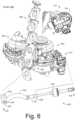
- the linkage assembly 630 includes a valve end 632 and an actuator end 634 where a linkage 622 includes a peg 624 operatively coupled to or part of the linkage assembly 630 and where the linkage 622 includes an opening or peg 626 operatively coupled to the bypass valve 620.
- the linkage assembly 630 includes an extension 635 with a relatively straight, axial portion 637 and a connector 639. As shown, the linkage assembly 630 includes a spring-biased linkage 640 that has an axial span from the connector 639 to the actuator end 634 of the linkage assembly 630.
- a four bar linkage approach can be utilized as part of a valve control mechanism.
- a spring-biased linkage can be included such as, for example, the spring-biased linkage 640 of Fig. 6 .
- Fig. 7 shows example states for an assembly that includes a valve plug 702, a valve seat 703, a rotatable shaft 712, a linkage 714, a linkage assembly 730 with an actuator end 734 and a valve end 734, a spring-biased linkage 740, and a linkage 722 that includes a linkage end 724 and a plug shaft end 726.
- the example states include an open state, a closed state and a locked state, which is shown as a closed and locked state.
- a hard-stop 711 is shown as a surface against which the linkage 714 may be biased against (e.g., a hard-stop surface).
- an electric actuator may consume little energy (e.g., parasitic consumption or vampire consumption) as the assembly can be maintained in the closed and locked state via mechanics including spring-biasing.
- a linkage assembly can include a spring-biased linkage where the linkage assembly includes a first link and a second link that are connected via the spring-biased linkage.
- two rigid links e.g., link assemblies
- a spring pack e.g., or spring package
- a linkage assembly can include rigid links (e.g., link assemblies) where one or both of the rigid links can be a piston or pistons that can slide in a cylindrical housing (e.g., bore) where one or more spring elements bias the piston or pistons.
- one of the rigid links can be fixed (e.g., to a spring pack housing or portion of a spring pack housing) and the other rigid link can be movable, such as being translatable along an axis of a linkage assembly, and spring-biased.
- Figs. 8A and 8B show a spring-biased linkage 840 in a side view ( Fig. 8A ) and in a cross-sectional cutaway view along a line A-A ( Fig. 8B ).
- the spring-biased linkage 840 includes coupling 842 and 844 that are operatively coupled to a spring package 850 that includes one or more spring elements 860.
- the axial displacement ⁇ z along the z-axis corresponds to an amount of displacement as to the coupling 842 with respect to the coupling 844.
- the coupling 844 is fixed to the spring package 850, as explained below, and the coupling 842 is axially translatable with respect to the spring package 850 and biased by the spring package 850 (e.g., one or more spring elements, etc. of the spring package 850).
- the spring package 850 includes a housing 851 with opposing end 852 and 854 and a chamber 853 as defined at least in part via the housing 851.
- the chamber 853 can be substantially cylindrical in shape where the one or more spring elements 860 are substantially cylindrical in shape.
- the chamber 853 can be defined at least in part via a bore surface of the housing 851, which may be a cylindrical bore surface.
- a rod assembly 870 includes, between opposing end 874 and 879, rod portions 875, 878 and 877 as well as piston portion 876 that moves with the rod portion 875 while the rod portions 877 and 878 are fixed to the housing 851 (e.g., immovably fixed to the housing 851).
- the rod portion 877 is fixed to the housing 851 (e.g., via matching exterior threads of the rod portion 877 and interior threads of the housing 851 while the piston portion 876 can be in contact with the one or more spring elements 860 to apply force thereto or to receive force therefrom where the one or more spring elements 860 are set within the chamber 853 of the housing 851 and where the one or more spring elements 860 define an opening through which the piston portion 876 of the rod assembly 870 passes.
- the one or more spring elements 860 are substantially aligned as an axial stack that form opposing end surfaces and an opening or bore that extends between the opposing end surfaces where one of the end surfaces is supported by a wall of the housing 851 that defines in part the chamber 853 and where the other of the end surfaces can be in contact with (e.g., directly or indirectly) the piston portion 876 of the rod or rod assembly 870.
- the piston portion 876 can include a cap portion (e.g., of a "T" shape) that may be a component that can be threaded into a threaded bore of the piston portion 876.
- the nut 894 may be utilized as part of an adjustment mechanism to adjust a load applied by the one or more spring elements 860.
- the nut 894 may adjust an axial limit as to the piston portion 876 of the rod assembly 870 with respect to the axial displacement ⁇ z (e.g., an axial throw limit, etc.).
- the load can be a preload that is set such that a load greater than the preload will cause the one or more spring element 860 to compress and shorten in axial length while opposing couplings 842 and 844 move in opposite directions along the z-axis to length the distance between the coupling feature 843 and the coupling feature 845.
- Figs. 8C and 8D show the spring package 850 in two states where one state (right) is a compressed state compared to another state that is limited in axial position by the nut 894, which may be a loaded state.
- the one or more spring elements 860 include a plurality of stacked spring washers (e.g., cone washers or coned washers). For example, about 1 to about 20 spring washers may be utilized, optionally with one or more flat washers. As an example, a number of spring washers and arrangement of spring washers may be utilized to achieve a desired load and/or spring constant.
- Fig. 8E shows a top view of the spring package 850
- Fig. 8F shows an example of the rod portion 876 that includes multiple pieces 876' and 876" that may be coupled together to form the rod portion 876.
- the piece 876' can be a rod piece and the piece 876" can be a cap piece where the pieces 876' and 876" are connectable via threads, bayonet, or another type of attachment mechanism.
- Fig. 8C various dimensions are shown such as an outer diameter (OD) D0 of the housing 851 and a threaded inner diameter (ID) D1 of the housing 851 (e.g., a threaded bore) for coupling of the rod portion 877 via matching threads on an outer diameter of the rod portion 877.
- the housing 851 may include threads at the outer diameter D0 where inner diameter threads of a coupling of a rod portion may be threaded thereto to connect a rod portion to the housing 851.
- Fig. 8C various dimensions are shown such as an outer diameter (OD) D0 of the housing 851 and a threaded inner diameter (ID) D1 of the housing 851 (e.g., a threaded bore) for coupling of the rod portion 877 via matching threads on an outer diameter of the rod portion 877.
- the housing 851 may include threads at the outer diameter D0 where inner diameter threads of a coupling of a rod portion may be threaded thereto to connect a rod portion to
- the rod portion 877 may be attached such that a threaded portion threads into the housing 851 and a cap portion (e.g., of a "T" shape) contacts the end 854 of the housing 851.
- the rod portion 877 can include an axial portion with a first diameter and an axial portion with a second larger diameter that can define a surface that can abut a surface of the housing 851 at the end 854.
- a coupling that includes ID threads may include a surface that can abut a surface of the housing.
- a washer e.g., a locking washer
- the dimensions illustrated also include an ID D2 of the housing 851, an OD D3 of the rod portion 876, an ID D4 of the housing 851, a threaded OD D5 of the rod portion 875 that mates with ID threads of the nut 894, and an OD D6 of the rod portion 875.
- the nut 894 can be adjusted with respect to the rod portion 875 to determine a load applied by the one or more spring elements 860 to the rod portion 876 (e.g., at its cap; see, e.g., top view of Fig. 8E and example of Fig. 8F ).
- the loaded state (left) can have a load adjusted via the number and/or arrangement of spring elements 860 and the nut 894.
- the load may be a base load where loading greater than the base load causes compression of the one or more spring elements 860.
- Figs. 9A and 9B show an example of a spring-biased linkage 940 in a side view ( Fig. 9A ) and in a cross-sectional cutaway view along a line A-A ( Fig. 9B ).
- the spring-biased linkage 940 includes coupling 942 and 944 that are operatively coupled to a spring package 950 that includes one or more spring elements 960.
- the axial displacement ⁇ z along the z-axis corresponds to an amount of displacement as to the coupling 942 with respect to the coupling 944.
- the coupling 944 is fixed to a portion of the spring package 950, as explained below, and the coupling 942 is axially translatable with respect to a portion of the spring package 950 and biased by the spring package 950.
- the spring package 950 includes housings 951-1 and 951-2 with opposing end 952 and 954 and chambers 953-1 and 953-2 as defined at least in part via the housings 951-1 and 951-2.
- the housing 951-1 is nested with respect to the housing 951-2 such that a portion of the housing 951-1 can move into and out of the chamber 953-2 as defined by the housing 951-2.
- the chambers 953-1 and 953-2 can be substantially cylindrical in shape where the one or more spring elements 960 are substantially cylindrical in shape.
- the coupling 944 extends into the housing 951-1 and 951-2 where an interference fit (e.g., a press-fit, etc.) may be made with respect to the housing 951-2 such that the coupling 944 is axially fixed (e.g., immovably) with respect to the housing 951-2.
- the piston portion 975 passes through a bore 948 of the coupling 944 and the coupling 944 includes axially elongated openings 949 through which the pin 992 extends.
- the rod assembly 970 can axially translate with the pin 992 to compress the one or more spring elements 960 or to receive a biasing force from the one or more spring elements 960.
- the aforementioned axial displacement ⁇ z may be determined, for example, by an axial length of the elongated openings 949.
- the piston portion 975 can be operatively coupled to the housing 951-1 (e.g., a first housing) via the pin 992 in the cross-bore 977 and the one or more spring elements 960 can be supported by the housing 951-2 (e.g., a second housing) such that force can be transmitted from the piston portion 975 to the one or more spring elements 960 and such that force can be transmitted from the one or more spring elements 960 to the piston portion 975.
- the housing 951-1 can move with respect to the housing 951-2 where spacing (e.g., clearance) between the housings 951-1 and 951-2 about the outer surface of the housing 951-1 and the inner surface of the housing 951-2 can be dimensioned to help to prevent debris from entering the spring package 950.
- the spring package 950 may operate as a spring-biased piston assembly where the rod assembly 970 acts as a piston that is biased by the one or more spring elements 960 as seated in the housings 951-1 and 951-2 (e.g., housing caps, etc.) of the spring package 950.
- the spring-biased linkage 940 may act as the linkage 730, or a portion thereof, of the assembly 700 of Fig. 7 .
- a coupling 942 includes a bore 946 that receives the piston portion 975 where the nut 996 may be utilized to determine an appropriate length as to a coupling feature 943 (e.g., an opening, etc.) of the coupling 942.
- a coupling feature 943 e.g., an opening, etc.
- the coupling 944 includes the bore 948 that receives the rod portion 978 where the coupling 944 is set at an appropriate length as to the housing 953-2 (e.g., via interference fit, welding, threads, crimping, a locking pin, a locking washer, etc.).
- Figs. 9C and 9D show the spring package 950 in two states where one state (right) is a compressed state compared to another state that is limited in axial position by the opening 949 in the coupling 944, which may be a loaded state.
- the one or more spring elements 960 include a plurality of stacked spring washers (e.g., cone washers or coned washers). For example, about 1 to about 20 spring washers may be utilized, optionally with one or more flat washers. As an example, a number of spring washers and arrangement of spring washers may be utilized to achieve a desired load and/or spring constant.
- various dimensions may be described, for example, with respect to a cylindrical coordinate system r, ⁇ and z.
- diameters and axial lengths may be defined for the various pieces as well as, for example, azimuthal positions such as the pin 992 being in the cross-bore 977 of the rod 970 where the coupling 944 includes the opening 949 as an elongated opening (e.g., oval, oblong, etc.) that can allow for positioning of the pin 992 as well as for determining an amount of load where a lower portion of the coupling 944 is coupled to the housing 951-2 in an axially immovable manner (e.g., interference fit, welding, threaded engagement, etc.).
- one or more features of the housing 951-2 and the coupling 944 can be one or more adjustment mechanism features that allow for adjustment of a preload (e.g., setting of a preload).
- the rod portion 975 translates in a bore 948 of the coupling 944 where the coupling 944 is fixed to the housing 951-2 and where the rod portion 975 is fixed via the pin 992 being received in the cross-bore 977 where the rod 970 includes the portion 978 axially above the pin 992 (e.g., the cross-bore 977) and the portion 975 below the pin 992 (e.g., the cross-bore 977).
- Fig. 9E shows a perspective view of the spring-biased linkage 940 including the spring package 950 where the pin 992 is received via the elongated openings 949 in the coupling 944 and received via the cross-bore 977 in the rod 970.
- the spring-biased linkage 940 can be loaded, for example, with a preload.
- a preload may be set via a positional relationship between the coupling 944 and the rod 970.
- the housing 951-2 can be fixed to the coupling 944 in a manner that positions the pin 992 with respect to respective top portions of the two elongated openings 949 (e.g., parallel to each other and axially extensive) where the one or more spring elements 960 can be in a compressed state.
- Fig. 9E the portion of the spring-biased linkage 940 is shown where the pin 992 is in contact with top portions of the elongated openings 949 as well as in contact with the end 954 of the spring package 950.
- the pin 992 is moved downwardly away from the top portions of the elongated openings 949.
- a force greater than the preload may further compress the one or more spring elements 960.
- a downward force that overcomes that preload can further compress the one or more spring elements 960 and move the pin 992 downward, which can lengthen the spring-biased linkage 940.
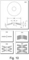
- Fig. 10 shows an example of a spring washer 1010 (e.g., a cone washer or a coned washer or a spring element), an example of a flat washer 1012 and examples of spring washer stacks 1014, 1016 and 1018 (e.g., spring element stacks).
- the spring washer 1010 may be made of metal or an alloy (e.g., a metallic material).
- a metallic material e.g., a metallic material.
- the spring washer 1010 can be a Belleville washer (e.g., a Belleville spring).
- the spring washer 1010 can be defined by an outer diameter (OD) and an inner diameter (ID) as well as by a thickness (t), a height (h) along an axis z (e.g., a central cone axis), which may be measured from a bottom surface to a bottom edge of the inner diameter (e.g., opening), and an overall height (Ho), as measured from a bottom to a top.
- the overall height (Ho) can be an uncompressed height where, upon loading, the height of the spring washer 1010 can decrease to a height less than the overall height (Ho).
- a plurality of the spring washers 1010 may be stacked to form one or more types of stacks, optionally including one or more flat washers such as the flat washer 1012.
- a stack height, a throw (e.g., ⁇ z), and a spring parameter for the throw may be determined.
- a throw may be a maximum expected throw that can allow for transitioning from one state to another state.
- Fig. 7 shows the open state, the closed state and the closed and locked state for an assembly.
- the spring-biased linkage 740 can allow the linkage assembly 730 to increase in its axial length between ends 732 and 734 (e.g., stretch) such that a maximum axial length is achieved during the transition from the closed state to the closed and locked state.
- the spring-biased linkage 740 in the closed and locked state, can decrease in its axial length between ends 732 and 734 (e.g., contract) and apply a load that may help to maintain the linkage assembly 730 in the closed and locked state.
- the load applied by the spring-biased linkage 740 may be sufficient to allow for an actuator to be in a low power state (e.g., vampire power state) or, for example, an off power state.
- the spring-biased linkage 740 can pull the end 734 against the surface 711 to maintain the valve plug 702 in a closed and locked state with respect to the valve seat 703.
- an actuator may apply an actuation force that causes the linkage assembly 730 to lengthen axially via the spring-biased linkage 740.
- the spring-biased linkage 740 may be at a substantially fixed axial length.
- axial length changes can be for transitions into and out of the closed and locked state (e.g., with respect to the closed state).
- a spring-biased linkage may be referred to as a spring-biased locking linkage that allow an assembly to be placed into a locked state.
- the spring-biased linkage 740, the spring-biased linkage 840 and/or the spring-biased linkage 940 may be spring-biased locking linkages.
- an actuator may be actuated (e.g., via electrical power) to transition from a closed and locked state to another state, which may be, for example, a closed and unlocked state or an open state.
- a closed and locked state may be, for example, a closed and unlocked state or an open state.
- one or more types of changes in demand may be associated with driving conditions, traffic signals, grade, etc.
- an actuator may optionally open a valve according to a control scheme that may be based on one or more factors (e.g., demand, pressure, etc.).
- regulation of the exhaust valve 125 can act to pilot the low pressure turbocharger 120-2.
- a controller may actuate the exhaust valve 125 (e.g., transition to an open state or more open state) to increase flow of exhaust to the turbine 126-2 (e.g., via physical diversion or pressure differential).
- the increased flow to the turbine 126-2 increases rotational speed of the shaft 122-2, which prepares the turbocharger 120-2 for a more rapid response and power output (e.g., with minimum turbo lag) upon configuration of the exhaust valve 125 in an orientation that causes full or significant bypass of the turbine 126-1.
- a biasing mechanism can include a plurality of stacked coned washers that may be referred to as spring washers.
- a biasing mechanism can include a plurality of Belleville washers, which can be coned washers (e.g., annular pieces of material that are angled as may be a portion of a cone).
- a coned washer can provide spring characteristics and may provide a relatively high fatigue life and a relatively high load capacity with a relatively small amount of deflection (e.g., of the order of millimeters, which may be less than about 10 mm or less than about 15 mm or less than about 25 mm).
- coned washers may be stacked to modify an effective spring constant and/or an amount of deflection.
- stacking in the same conical direction can add to an effective spring constant in parallel, for example, to create a stiffer joint (e.g., with the same deflection); whereas, stacking in alternating conical directions can effectively be akin to adding springs in series, resulting in a lower spring constant and greater deflection.
- a biasing element can include stacking in one direction or stacking in two directions, for example, to tailor spring behavior and deflection.
- a 2-Stage TBV (Turbine Bypass Valve) mechanism can act to have a valve held closed against exhaust gas manifold pressure, for example, at low power/low engine RPM operating points. Relatively high pressure differentials across such a valve can require a relatively large, continuous actuator force to be applied to the mechanism.
- Various electric actuators may not necessarily be suited to high, continuous load operating conditions (e.g., due to the resistive heating of the actuator motor coils which can limit available peak, continuous force.
- vacuum pneumatic actuators may be used for these applications but they require a vacuum source (e.g., an engine mounted vacuum pump) and are more suited to on-off type operation rather than fine-control actuation which is desirable during the 2-stage system transition from the high pressure turbo to the low pressure turbo.
- a vacuum source e.g., an engine mounted vacuum pump
- Fig. 11 shows example states that include an open state 1102, a closed state 1104 and a dead-point state 1106, an example plot 1107 as to behavior of a spring-biased linkage and also shows an example plot 1110 that includes operational paths (e.g., path segments) and states that are illustrated with respect to crank angle and actuator torque.
- operational paths e.g., path segments
- the example dead-point state 1106 is illustrated with a dimension ⁇ z, which indicates an amount by which the linkage is extended in length compared to, for example, the example open state 1102 and the example closed state 1104; noting that an example hard-stop state can include a length that is less than for the example dead-point state 1106.
- the axial length of the linkage can increase in the closed state 1104 where a valve plug is in contact with a valve seat of the exhaust bypass valve. In such a state, contact force between the valve plug and the valve seat can increase, which can increase sealing of the exhaust bypass valve, for example, with respect to an exhaust gas pressure differential where exhaust pressure is greater on a valve seat side than a valve plug side of the exhaust bypass valve.
- a spring-biased linkage can include a preload of value F P where application of force (e.g., load) F in excess of the preload value F P causes the spring-biased linkage to increase in its axial length.
- a particular length of the spring-biased linkage can be for a dead-point force (e.g., dead-point load), indicated by F DP , which is shown to correspond to an axial increase in length of ⁇ z, which, in the example of Fig. 11 , occurs after the closed state 1104.
- a spring-biased linkage can include a rod and at least one cone washer that includes an opening where the rod is disposed in the opening.
Landscapes
- Engineering & Computer Science (AREA)
- Chemical & Material Sciences (AREA)
- Combustion & Propulsion (AREA)
- Mechanical Engineering (AREA)
- General Engineering & Computer Science (AREA)
- Supercharger (AREA)
Claims (13)
- Baugruppe für ein Abgasumgehungsventil eines zweistufigen Turboladers (600), wobei die Baugruppe Folgendes umfasst:eine erste Turboladerstufe (602);eine zweite Turboladerstufe (604);ein Abgasumgehungsventil (620), das einen geöffneten Zustand, einen geschlossenen Zustand sowie einen geschlossenen und verriegelten Zustand umfasst;ein Stellglied (610); undeinen Verbindungsmechanismus (630), der das Abgasumgehungsventil mit dem Stellglied verbindet, wobei der Verbindungsmechanismus ein federvorgespanntes Gestänge (640) mit einer voreingestellten Last umfasst, wobei das federvorgespannte Gestänge ein Gehäuse, eine an das Gehäuse befestigte Stange (878, 944) und eine gegenüberliegende federvorgespannte Stange (875, 975), die in Bezug auf das Gehäuse verschiebbar ist, und einen Lastanpassungsmechanismus zum Einstellen des federvorgespannten Gestänges auf die voreingestellte Last umfasst, wobei der Lastanpassungsmechanismus einen axialen Abstand zwischen der Stange und der gegenüberliegenden Stange des federvorgespannten Gestänges einstellt, und wobei:(1) im geschlossenen Zustand des Abgasumgehungsventils eine axiale Länge des federvorgespannten Gestänges in Reaktion auf das Ausüben einer Last durch das Stellglied, die die voreingestellte Last übersteigt, zunimmt;(2) in einer Ausrichtung zwischen dem geschlossenen Zustand und dem geschlossenen und verriegelten Zustand das federvorgespannte Gestänge eine maximale axiale Länge hat; und(3) im geschlossen und verriegelten Zustand das federvorgespannte Gestänge eine Verriegelungskraft ausübt.
- Baugruppe nach Anspruch 1, wobei das Gehäuse eine Kammer (414, 853, 953) definiert, und wobei mindestens eine konische Unterlegscheibe in der Kammer angeordnet ist.
- Baugruppe nach Anspruch 1, wobei das federvorgespannte Gestänge ein erstes Gehäuse (951-1) umfasst, das in Bezug auf das zweite Gehäuse (951-2) axial verschiebbar ist, wobei die Stange (944) an das erste Gehäuse befestigt ist und die gegenüberliegende federvorgespannte Stange (975) an das zweite Gehäuse befestigt ist.
- Baugruppe nach Anspruch 3, wobei das erste Gehäuse und das zweite Gehäuse eine Kammer (953-1, 953-2) definieren, und wobei mindestens eine konische Unterlegscheibe in der Kammer angeordnet ist.
- Baugruppe nach Anspruch 1, die mindestens eine konische Unterlegscheibe (960, 1010) umfasst.
- Baugruppe nach Anspruch 5, die eine Vielzahl von konischen Unterlegscheiben umfasst.
- Baugruppe nach Anspruch 5, die mindestens eine flache Unterlegscheibe (1012) umfasst, die axial zwischen zwei aus einer Vielzahl von konischen Unterlegscheiben angeordnet ist.
- Baugruppe nach Anspruch 1, wobei das federvorgespannte Gestänge mindestens eine konische Unterlegscheibe umfasst, die eine Öffnung umfasst, wobei die Stange in der Öffnung angeordnet ist.
- Baugruppe nach Anspruch 1, wobei das Stellglied ein elektrisches Stellglied umfasst.
- Baugruppe nach Anspruch 9, wobei das elektrische Stellglied einen elektrischen Motor umfasst, der eine Welle umfasst, die betriebsmäßig mit dem Verbindungsmechanismus gekoppelt ist.
- Baugruppe nach Anspruch 1, wobei das Abgasumgehungsventil im geöffneten Zustand ermöglicht, das mindestens ein Teil des Abgases eines Verbrennungsmotors eine der Turboladerstufen umgeht.
- Baugruppe nach Anspruch 1, wobei die erste Turboladerstufe eine Stufe mit einem niedrigen Abgasdurchfluss umfasst, und wobei die zweite Turboladerstufe eine Stufe mit einem hohen Abgasdurchfluss umfasst.
- Baugruppe nach Anspruch 1, wobei im geöffneten Zustand des Abgasumgehungsventils für mindestens einen Teil des Abgases eines Verbrennungsmotors ein Pfad vorhanden ist, um eine erste Turboladerstufe zu umgehen.
Applications Claiming Priority (1)
| Application Number | Priority Date | Filing Date | Title |
|---|---|---|---|
| US15/273,595 US10697361B2 (en) | 2016-09-22 | 2016-09-22 | Linkage for exhaust bypass valve of multi-stage turbocharger |
Publications (2)
| Publication Number | Publication Date |
|---|---|
| EP3299602A1 EP3299602A1 (de) | 2018-03-28 |
| EP3299602B1 true EP3299602B1 (de) | 2025-03-26 |
Family
ID=59901408
Family Applications (1)
| Application Number | Title | Priority Date | Filing Date |
|---|---|---|---|
| EP17191498.9A Active EP3299602B1 (de) | 2016-09-22 | 2017-09-15 | Verbindung für ein abgasumgehungsventil eines mehrstufigen turboladers |
Country Status (3)
| Country | Link |
|---|---|
| US (1) | US10697361B2 (de) |
| EP (1) | EP3299602B1 (de) |
| CN (1) | CN107869386B (de) |
Families Citing this family (10)
| Publication number | Priority date | Publication date | Assignee | Title |
|---|---|---|---|---|
| US8991840B2 (en) * | 2013-03-14 | 2015-03-31 | Oshkosh Defense, Llc | Load dependent damper for a vehicle suspension system |
| US11203970B2 (en) | 2018-09-21 | 2021-12-21 | Borgwarner Inc. | Wastegate assembly |
| CN215370025U (zh) | 2018-09-21 | 2021-12-31 | 博格华纳公司 | 废气门组件和涡轮增压器 |
| DE102018217039A1 (de) * | 2018-10-04 | 2020-04-09 | Continental Automotive Gmbh | Abgasturbolader mit einer aktuatorbetätigten Stellvorrichtung und einem Übertragungselement |
| CN214036915U (zh) | 2019-09-20 | 2021-08-24 | 博格华纳公司 | 废气门组件和涡轮增压器 |
| US11859525B2 (en) * | 2020-08-01 | 2024-01-02 | Andrew Hlava | Turbocharger manifold, system, and method |
| DE112020007240B4 (de) * | 2020-08-17 | 2025-12-11 | Mitsubishi Heavy Industries Engine & Turbocharger, Ltd. | Wastegateventilvorrichtung, turbine und turbolader |
| US11333064B1 (en) * | 2021-05-11 | 2022-05-17 | Garrett Transportation I Inc. | Turbocharger bypass valve and actuator assembly therefor having guided toggle |
| CN116045063B (zh) * | 2023-03-08 | 2023-06-20 | 江苏毅合捷汽车科技股份有限公司 | 用于多级涡轮增压器的排气旁通阀的连杆 |
| US12209599B1 (en) | 2023-03-22 | 2025-01-28 | Savant Holdings LLC | Multi-stage actuator for a turbocharger |
Family Cites Families (19)
| Publication number | Priority date | Publication date | Assignee | Title |
|---|---|---|---|---|
| US3851538A (en) * | 1973-05-21 | 1974-12-03 | Philadelphia Gear Corp | Torque switch mechanism |
| JPH0351546Y2 (de) * | 1986-01-07 | 1991-11-06 | ||
| US5487273A (en) * | 1993-09-13 | 1996-01-30 | Alliedsignal Inc. | Turbocharger having pneumatic actuator with pilot valve |
| JP2000213584A (ja) * | 1999-01-26 | 2000-08-02 | Honda Motor Co Ltd | 車両用懸架装置の初期設定荷重調整装置 |
| GB2370865A (en) | 2000-12-27 | 2002-07-10 | Luk Lamellen & Kupplungsbau | A compliant link |
| DE102009051623A1 (de) * | 2009-11-02 | 2011-05-05 | Robert Bosch Gmbh | Stelleinrichtung für eine Ventilklappe |
| US9322327B2 (en) * | 2009-11-03 | 2016-04-26 | Honeywell International Inc. | Turbocharger with bypass valve providing complete bypass of the turbine for improved catalyst light-off |
| DE102010001210A1 (de) * | 2010-01-26 | 2011-07-28 | Robert Bosch GmbH, 70469 | Getriebeanordnung sowie Abgasturbolader |
| US8353153B2 (en) | 2010-02-25 | 2013-01-15 | Tenneco Automotive Operating Company Inc. | Snapper valve for hot end systems with burners |
| DE102010020115A1 (de) * | 2010-05-10 | 2011-11-10 | Continental Automotive Gmbh | Einrichtung zur Ansteuerung eines Abgasventils einer Brennkraftmaschine |
| US8667794B2 (en) | 2011-06-01 | 2014-03-11 | Honeywell International Inc. | Valve seat and gasket for exhaust bypass valve |
| DE102012203849A1 (de) * | 2012-03-13 | 2013-09-19 | Continental Automotive Gmbh | Abgasturbolader mit einem Wastegateventil und einem Schubumluftventil |
| US9206735B2 (en) | 2012-08-02 | 2015-12-08 | Honeywell International Inc. | Actuator and valve linkage |
| JP6066664B2 (ja) * | 2012-10-30 | 2017-01-25 | ダイハツ工業株式会社 | 内燃機関 |
| DE102013213558B4 (de) * | 2013-07-11 | 2021-12-23 | Vitesco Technologies GmbH | Vorrichtung zur Betätigung der Wastegateklappe eines Abgasturboladers |
| CN103511063B (zh) * | 2013-10-29 | 2017-12-05 | 汉美综合科技(常州)有限公司 | 可调背靠背双侧叶轮涡轮增压器 |
| JP6171870B2 (ja) * | 2013-11-12 | 2017-08-02 | 株式会社Ihi | ダイヤフラム式アクチュエータ及び過給機 |
| CN104295838B (zh) * | 2014-09-19 | 2016-03-09 | 慈溪市宗汉中正快速接头厂(普通合伙) | 一种省力流体快速连接器 |
| CN104791500A (zh) * | 2015-04-17 | 2015-07-22 | 泰州市自立环保管件设备厂 | 一种船用超强耐腐蚀不锈钢铸件阀体 |
-
2016
- 2016-09-22 US US15/273,595 patent/US10697361B2/en active Active
-
2017
- 2017-09-15 EP EP17191498.9A patent/EP3299602B1/de active Active
- 2017-09-21 CN CN201710859761.6A patent/CN107869386B/zh active Active
Also Published As
| Publication number | Publication date |
|---|---|
| CN107869386B (zh) | 2021-11-12 |
| CN107869386A (zh) | 2018-04-03 |
| US20180080370A1 (en) | 2018-03-22 |
| EP3299602A1 (de) | 2018-03-28 |
| US10697361B2 (en) | 2020-06-30 |
Similar Documents
| Publication | Publication Date | Title |
|---|---|---|
| US10697361B2 (en) | Linkage for exhaust bypass valve of multi-stage turbocharger | |
| EP2321508B1 (de) | Drosselventil für turboladersysteme | |
| US9488182B2 (en) | Control shaft seal | |
| US8033109B2 (en) | Variable-nozzle assembly for a turbocharger | |
| EP1260676B1 (de) | Steuerungsmethode für eine variable Einlassdüse einer Turbine | |
| EP2530275B1 (de) | Ventilsitz und Dichtung für Auspuffumgehungsventil | |
| CN1451076A (zh) | 可变几何尺寸的涡轮增压器 | |
| US8122716B2 (en) | VNT flow calibration adjustment | |
| US20070154302A1 (en) | Geared inlet guide vane for a centrifugal compressor | |
| EP3139017B1 (de) | Belastete wastegate-steuergestängeverbindungen einer turboladerturbine | |
| EP3133260B1 (de) | Wastegate-steuergestängeverbindungen einer belasteten turboladerturbine | |
| CN110513159B (zh) | 具有单轴、自定心枢转特征件的可变涡轮几何形状叶片 | |
| EP2818668A1 (de) | Turbinenaustrittsdichtung | |
| EP3430240B1 (de) | Turbinenanordnung | |
| EP3179069B1 (de) | Abgasumgehungsventil eines mehrstufigen turboladers | |
| EP3118434B1 (de) | Aktuator-verbindung für ein abgas-bypass-ventil eines mehrstufigen turboladers | |
| JP2010270738A (ja) | 弁装置、内燃機関、及び弁装置の制御方法 | |
| US10941700B2 (en) | Turbocharger turbine wastegate assembly | |
| US20200063597A1 (en) | Variable-stator-vane actuation system |
Legal Events
| Date | Code | Title | Description |
|---|---|---|---|
| PUAI | Public reference made under article 153(3) epc to a published international application that has entered the european phase |
Free format text: ORIGINAL CODE: 0009012 |
|
| STAA | Information on the status of an ep patent application or granted ep patent |
Free format text: STATUS: REQUEST FOR EXAMINATION WAS MADE |
|
| 17P | Request for examination filed |
Effective date: 20170915 |
|
| AK | Designated contracting states |
Kind code of ref document: A1 Designated state(s): AL AT BE BG CH CY CZ DE DK EE ES FI FR GB GR HR HU IE IS IT LI LT LU LV MC MK MT NL NO PL PT RO RS SE SI SK SM TR |
|
| AX | Request for extension of the european patent |
Extension state: BA ME |
|
| RAP1 | Party data changed (applicant data changed or rights of an application transferred) |
Owner name: GARRETT TRANSPORTATION I INC. |
|
| STAA | Information on the status of an ep patent application or granted ep patent |
Free format text: STATUS: EXAMINATION IS IN PROGRESS |
|
| 17Q | First examination report despatched |
Effective date: 20210604 |
|
| P01 | Opt-out of the competence of the unified patent court (upc) registered |
Effective date: 20230424 |
|
| GRAP | Despatch of communication of intention to grant a patent |
Free format text: ORIGINAL CODE: EPIDOSNIGR1 |
|
| STAA | Information on the status of an ep patent application or granted ep patent |
Free format text: STATUS: GRANT OF PATENT IS INTENDED |
|
| GRAS | Grant fee paid |
Free format text: ORIGINAL CODE: EPIDOSNIGR3 |
|
| INTG | Intention to grant announced |
Effective date: 20250116 |
|
| GRAA | (expected) grant |
Free format text: ORIGINAL CODE: 0009210 |
|
| STAA | Information on the status of an ep patent application or granted ep patent |
Free format text: STATUS: THE PATENT HAS BEEN GRANTED |
|
| AK | Designated contracting states |
Kind code of ref document: B1 Designated state(s): AL AT BE BG CH CY CZ DE DK EE ES FI FR GB GR HR HU IE IS IT LI LT LU LV MC MK MT NL NO PL PT RO RS SE SI SK SM TR |
|
| REG | Reference to a national code |
Ref country code: GB Ref legal event code: FG4D |
|
| REG | Reference to a national code |
Ref country code: CH Ref legal event code: EP |
|
| REG | Reference to a national code |
Ref country code: DE Ref legal event code: R096 Ref document number: 602017088509 Country of ref document: DE |
|
| REG | Reference to a national code |
Ref country code: IE Ref legal event code: FG4D |
|
| PG25 | Lapsed in a contracting state [announced via postgrant information from national office to epo] |
Ref country code: RS Free format text: LAPSE BECAUSE OF FAILURE TO SUBMIT A TRANSLATION OF THE DESCRIPTION OR TO PAY THE FEE WITHIN THE PRESCRIBED TIME-LIMIT Effective date: 20250626 |
|
| PG25 | Lapsed in a contracting state [announced via postgrant information from national office to epo] |
Ref country code: FI Free format text: LAPSE BECAUSE OF FAILURE TO SUBMIT A TRANSLATION OF THE DESCRIPTION OR TO PAY THE FEE WITHIN THE PRESCRIBED TIME-LIMIT Effective date: 20250326 |
|
| REG | Reference to a national code |
Ref country code: LT Ref legal event code: MG9D |
|
| PG25 | Lapsed in a contracting state [announced via postgrant information from national office to epo] |
Ref country code: NO Free format text: LAPSE BECAUSE OF FAILURE TO SUBMIT A TRANSLATION OF THE DESCRIPTION OR TO PAY THE FEE WITHIN THE PRESCRIBED TIME-LIMIT Effective date: 20250626 |
|
| PG25 | Lapsed in a contracting state [announced via postgrant information from national office to epo] |
Ref country code: HR Free format text: LAPSE BECAUSE OF FAILURE TO SUBMIT A TRANSLATION OF THE DESCRIPTION OR TO PAY THE FEE WITHIN THE PRESCRIBED TIME-LIMIT Effective date: 20250326 |
|
| PG25 | Lapsed in a contracting state [announced via postgrant information from national office to epo] |
Ref country code: LV Free format text: LAPSE BECAUSE OF FAILURE TO SUBMIT A TRANSLATION OF THE DESCRIPTION OR TO PAY THE FEE WITHIN THE PRESCRIBED TIME-LIMIT Effective date: 20250326 |
|
| PG25 | Lapsed in a contracting state [announced via postgrant information from national office to epo] |
Ref country code: BG Free format text: LAPSE BECAUSE OF FAILURE TO SUBMIT A TRANSLATION OF THE DESCRIPTION OR TO PAY THE FEE WITHIN THE PRESCRIBED TIME-LIMIT Effective date: 20250326 Ref country code: GR Free format text: LAPSE BECAUSE OF FAILURE TO SUBMIT A TRANSLATION OF THE DESCRIPTION OR TO PAY THE FEE WITHIN THE PRESCRIBED TIME-LIMIT Effective date: 20250627 |
|
| REG | Reference to a national code |
Ref country code: NL Ref legal event code: MP Effective date: 20250326 |
|
| PG25 | Lapsed in a contracting state [announced via postgrant information from national office to epo] |
Ref country code: NL Free format text: LAPSE BECAUSE OF FAILURE TO SUBMIT A TRANSLATION OF THE DESCRIPTION OR TO PAY THE FEE WITHIN THE PRESCRIBED TIME-LIMIT Effective date: 20250326 |
|
| PG25 | Lapsed in a contracting state [announced via postgrant information from national office to epo] |
Ref country code: SE Free format text: LAPSE BECAUSE OF FAILURE TO SUBMIT A TRANSLATION OF THE DESCRIPTION OR TO PAY THE FEE WITHIN THE PRESCRIBED TIME-LIMIT Effective date: 20250326 |
|
| REG | Reference to a national code |
Ref country code: AT Ref legal event code: MK05 Ref document number: 1779167 Country of ref document: AT Kind code of ref document: T Effective date: 20250326 |
|
| PG25 | Lapsed in a contracting state [announced via postgrant information from national office to epo] |
Ref country code: SM Free format text: LAPSE BECAUSE OF FAILURE TO SUBMIT A TRANSLATION OF THE DESCRIPTION OR TO PAY THE FEE WITHIN THE PRESCRIBED TIME-LIMIT Effective date: 20250326 |
|
| PG25 | Lapsed in a contracting state [announced via postgrant information from national office to epo] |
Ref country code: PT Free format text: LAPSE BECAUSE OF FAILURE TO SUBMIT A TRANSLATION OF THE DESCRIPTION OR TO PAY THE FEE WITHIN THE PRESCRIBED TIME-LIMIT Effective date: 20250728 Ref country code: ES Free format text: LAPSE BECAUSE OF FAILURE TO SUBMIT A TRANSLATION OF THE DESCRIPTION OR TO PAY THE FEE WITHIN THE PRESCRIBED TIME-LIMIT Effective date: 20250326 |
|
| PGFP | Annual fee paid to national office [announced via postgrant information from national office to epo] |
Ref country code: DE Payment date: 20250926 Year of fee payment: 9 |
|
| PG25 | Lapsed in a contracting state [announced via postgrant information from national office to epo] |
Ref country code: PL Free format text: LAPSE BECAUSE OF FAILURE TO SUBMIT A TRANSLATION OF THE DESCRIPTION OR TO PAY THE FEE WITHIN THE PRESCRIBED TIME-LIMIT Effective date: 20250326 Ref country code: IT Free format text: LAPSE BECAUSE OF FAILURE TO SUBMIT A TRANSLATION OF THE DESCRIPTION OR TO PAY THE FEE WITHIN THE PRESCRIBED TIME-LIMIT Effective date: 20250326 |
|
| PGFP | Annual fee paid to national office [announced via postgrant information from national office to epo] |
Ref country code: GB Payment date: 20250923 Year of fee payment: 9 |
|
| PG25 | Lapsed in a contracting state [announced via postgrant information from national office to epo] |
Ref country code: AT Free format text: LAPSE BECAUSE OF FAILURE TO SUBMIT A TRANSLATION OF THE DESCRIPTION OR TO PAY THE FEE WITHIN THE PRESCRIBED TIME-LIMIT Effective date: 20250326 |
|
| PGFP | Annual fee paid to national office [announced via postgrant information from national office to epo] |
Ref country code: FR Payment date: 20250925 Year of fee payment: 9 |
|
| PG25 | Lapsed in a contracting state [announced via postgrant information from national office to epo] |
Ref country code: EE Free format text: LAPSE BECAUSE OF FAILURE TO SUBMIT A TRANSLATION OF THE DESCRIPTION OR TO PAY THE FEE WITHIN THE PRESCRIBED TIME-LIMIT Effective date: 20250326 |
|
| PG25 | Lapsed in a contracting state [announced via postgrant information from national office to epo] |
Ref country code: RO Free format text: LAPSE BECAUSE OF FAILURE TO SUBMIT A TRANSLATION OF THE DESCRIPTION OR TO PAY THE FEE WITHIN THE PRESCRIBED TIME-LIMIT Effective date: 20250326 |
|
| PG25 | Lapsed in a contracting state [announced via postgrant information from national office to epo] |
Ref country code: SK Free format text: LAPSE BECAUSE OF FAILURE TO SUBMIT A TRANSLATION OF THE DESCRIPTION OR TO PAY THE FEE WITHIN THE PRESCRIBED TIME-LIMIT Effective date: 20250326 |
|
| PG25 | Lapsed in a contracting state [announced via postgrant information from national office to epo] |
Ref country code: IS Free format text: LAPSE BECAUSE OF FAILURE TO SUBMIT A TRANSLATION OF THE DESCRIPTION OR TO PAY THE FEE WITHIN THE PRESCRIBED TIME-LIMIT Effective date: 20250726 |
|
| REG | Reference to a national code |
Ref country code: DE Ref legal event code: R097 Ref document number: 602017088509 Country of ref document: DE |
|
| PG25 | Lapsed in a contracting state [announced via postgrant information from national office to epo] |
Ref country code: DK Free format text: LAPSE BECAUSE OF FAILURE TO SUBMIT A TRANSLATION OF THE DESCRIPTION OR TO PAY THE FEE WITHIN THE PRESCRIBED TIME-LIMIT Effective date: 20250326 |
|
| PG25 | Lapsed in a contracting state [announced via postgrant information from national office to epo] |
Ref country code: CZ Free format text: LAPSE BECAUSE OF FAILURE TO SUBMIT A TRANSLATION OF THE DESCRIPTION OR TO PAY THE FEE WITHIN THE PRESCRIBED TIME-LIMIT Effective date: 20250326 |
|
| PLBE | No opposition filed within time limit |
Free format text: ORIGINAL CODE: 0009261 |
|
| STAA | Information on the status of an ep patent application or granted ep patent |
Free format text: STATUS: NO OPPOSITION FILED WITHIN TIME LIMIT |
|
| REG | Reference to a national code |
Ref country code: CH Ref legal event code: L10 Free format text: ST27 STATUS EVENT CODE: U-0-0-L10-L00 (AS PROVIDED BY THE NATIONAL OFFICE) Effective date: 20260211 |
|
| 26N | No opposition filed |
Effective date: 20260105 |
|
| REG | Reference to a national code |
Ref country code: CH Ref legal event code: H13 Free format text: ST27 STATUS EVENT CODE: U-0-0-H10-H13 (AS PROVIDED BY THE NATIONAL OFFICE) Effective date: 20260504 |