EP3299582B1 - Dichtungseinrichtung und gasturbine mit einer dichtungseinrichtung - Google Patents
Dichtungseinrichtung und gasturbine mit einer dichtungseinrichtung Download PDFInfo
- Publication number
- EP3299582B1 EP3299582B1 EP17191919.4A EP17191919A EP3299582B1 EP 3299582 B1 EP3299582 B1 EP 3299582B1 EP 17191919 A EP17191919 A EP 17191919A EP 3299582 B1 EP3299582 B1 EP 3299582B1
- Authority
- EP
- European Patent Office
- Prior art keywords
- outer seal
- extension
- leaf
- seal
- circumferentially
- Prior art date
- Legal status (The legal status is an assumption and is not a legal conclusion. Google has not performed a legal analysis and makes no representation as to the accuracy of the status listed.)
- Active
Links
Images




Classifications
-
- F—MECHANICAL ENGINEERING; LIGHTING; HEATING; WEAPONS; BLASTING
- F23—COMBUSTION APPARATUS; COMBUSTION PROCESSES
- F23R—GENERATING COMBUSTION PRODUCTS OF HIGH PRESSURE OR HIGH VELOCITY, e.g. GAS-TURBINE COMBUSTION CHAMBERS
- F23R3/00—Continuous combustion chambers using liquid or gaseous fuel
-
- F—MECHANICAL ENGINEERING; LIGHTING; HEATING; WEAPONS; BLASTING
- F01—MACHINES OR ENGINES IN GENERAL; ENGINE PLANTS IN GENERAL; STEAM ENGINES
- F01D—NON-POSITIVE DISPLACEMENT MACHINES OR ENGINES, e.g. STEAM TURBINES
- F01D9/00—Stators
- F01D9/02—Nozzles; Nozzle boxes; Stator blades; Guide conduits, e.g. individual nozzles
- F01D9/023—Transition ducts between combustor cans and first stage of the turbine in gas-turbine engines; their cooling or sealings
-
- F—MECHANICAL ENGINEERING; LIGHTING; HEATING; WEAPONS; BLASTING
- F01—MACHINES OR ENGINES IN GENERAL; ENGINE PLANTS IN GENERAL; STEAM ENGINES
- F01D—NON-POSITIVE DISPLACEMENT MACHINES OR ENGINES, e.g. STEAM TURBINES
- F01D9/00—Stators
- F01D9/02—Nozzles; Nozzle boxes; Stator blades; Guide conduits, e.g. individual nozzles
- F01D9/04—Nozzles; Nozzle boxes; Stator blades; Guide conduits, e.g. individual nozzles forming ring or sector
-
- F—MECHANICAL ENGINEERING; LIGHTING; HEATING; WEAPONS; BLASTING
- F02—COMBUSTION ENGINES; HOT-GAS OR COMBUSTION-PRODUCT ENGINE PLANTS
- F02C—GAS-TURBINE PLANTS; AIR INTAKES FOR JET-PROPULSION PLANTS; CONTROLLING FUEL SUPPLY IN AIR-BREATHING JET-PROPULSION PLANTS
- F02C3/00—Gas-turbine plants characterised by the use of combustion products as the working fluid
- F02C3/04—Gas-turbine plants characterised by the use of combustion products as the working fluid having a turbine driving a compressor
-
- F—MECHANICAL ENGINEERING; LIGHTING; HEATING; WEAPONS; BLASTING
- F02—COMBUSTION ENGINES; HOT-GAS OR COMBUSTION-PRODUCT ENGINE PLANTS
- F02C—GAS-TURBINE PLANTS; AIR INTAKES FOR JET-PROPULSION PLANTS; CONTROLLING FUEL SUPPLY IN AIR-BREATHING JET-PROPULSION PLANTS
- F02C7/00—Features, components parts, details or accessories, not provided for in, or of interest apart form groups F02C1/00 - F02C6/00; Air intakes for jet-propulsion plants
- F02C7/28—Arrangement of seals
-
- F—MECHANICAL ENGINEERING; LIGHTING; HEATING; WEAPONS; BLASTING
- F16—ENGINEERING ELEMENTS AND UNITS; GENERAL MEASURES FOR PRODUCING AND MAINTAINING EFFECTIVE FUNCTIONING OF MACHINES OR INSTALLATIONS; THERMAL INSULATION IN GENERAL
- F16J—PISTONS; CYLINDERS; SEALINGS
- F16J15/00—Sealings
- F16J15/16—Sealings between relatively-moving surfaces
-
- F—MECHANICAL ENGINEERING; LIGHTING; HEATING; WEAPONS; BLASTING
- F05—INDEXING SCHEMES RELATING TO ENGINES OR PUMPS IN VARIOUS SUBCLASSES OF CLASSES F01-F04
- F05D—INDEXING SCHEME FOR ASPECTS RELATING TO NON-POSITIVE-DISPLACEMENT MACHINES OR ENGINES, GAS-TURBINES OR JET-PROPULSION PLANTS
- F05D2220/00—Application
- F05D2220/30—Application in turbines
- F05D2220/32—Application in turbines in gas turbines
-
- F—MECHANICAL ENGINEERING; LIGHTING; HEATING; WEAPONS; BLASTING
- F23—COMBUSTION APPARATUS; COMBUSTION PROCESSES
- F23R—GENERATING COMBUSTION PRODUCTS OF HIGH PRESSURE OR HIGH VELOCITY, e.g. GAS-TURBINE COMBUSTION CHAMBERS
- F23R2900/00—Special features of, or arrangements for continuous combustion chambers; Combustion processes therefor
- F23R2900/00012—Details of sealing devices
Definitions
- the combustible mixture is burned to produce combustion gases having a high temperature and pressure.
- the combustion gases flow through a turbine of a turbine section wherein energy (kinetic and/or thermal) is transferred from the combustion gases to rotor blades, thus causing a shaft to rotate and produce work.
- the rotation of the turbine shaft may drive the compressor to produce the compressed working fluid.
- the shaft may connect the turbine to a generator for producing electricity.
- Exhaust gases from the turbine flow through an exhaust section that connects the turbine to an exhaust stack downstream from the turbine.
- the exhaust section may include, for example, a heat recovery steam generator for cleaning and extracting additional heat from the exhaust gases prior to release to the environment.
- FIG. 2 is the central axis A of turbine 18, which defines an axial direction that is substantially parallel to and/or coaxially aligned with axis A, a radial direction perpendicular to axis A, and a circumferential direction extending around axis A.
- inner seal 200 and outer seal 300 are circumferentially oriented, each inner seal 200 is circumferentially aligned with the other inner seal 200 on the adjacent aft frame 100, and each outer seal 300 is circumferentially aligned with the other outer seal 300 on the adjacent aft frame 100.
- the aft frame 100 may include a forward face 110 and an aft face 112.
- the intersections of side portions 106 and 108 with inner portion 102 define inner corners 120 and 122, and the intersections of side portions 106 and 108 with outer portion 104 define outer corners 130 and 132.
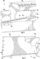
- FIG. 4 illustrates an outer seal 300 according to at least one embodiment of the present subject matter.
- Outer seal 300 includes a main body 302 which is generally circumferentially coextensive with the outer portion 104 of aft frame 100.
- Main body 302 includes a circumferentially oriented frame rail 304 and an axially oriented leaf 308.
- the outer seal 300 further includes a frame rail extension 306 that extends circumferentially beyond the main body 302 and a leaf extension 310 that extends circumferentially beyond the main body 302.
- a deflection limiter 309 is provided radially inward of leaf extension 310, and in particular a corner extension 307 ( FIG. 5 ) thereof. Deflection limiter 309 reinforces corner extension 307 to avoid or minimize corner extension 307 bending radially inward, away from axial leaf 412 ( FIGS. 8 & 9 ) under pressure from compressed air 26 ( FIG. 2 ).
- outer seal 300 generally comprises primarily a cloth material 312, which can be a woven mesh cloth of a suitable metal material, e.g., alloy L605.
- the cloth material 312 is supported by frame rail 304 and various shims 314.
- the cloth material 312 extends generally axially away from the frame rail 304 in the aft direction, such that cloth material 312 and supporting shim 314 form axially oriented leaf 308.
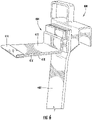
- FIG. 9 illustrates a perspective view of an exemplary sealing arrangement according to at least one embodiment of the present subject matter.
- the view of FIG. 9 is looking radially inward, which may more generally be characterized as looking down at the top of outer seals 300 and side seal 400.
- the adjacent outer seals 300 and side seal 400 cooperate to at least substantially occlude circumferential installation clearance X between adjacent aft frames 100.
- each frame rail extension 306 and each leaf extension 310 extends towards the corresponding frame rail extension 306 and leaf extension 310 on the adjacent outer seal 300. Also illustrated in FIG.
Landscapes
- Engineering & Computer Science (AREA)
- General Engineering & Computer Science (AREA)
- Mechanical Engineering (AREA)
- Chemical & Material Sciences (AREA)
- Combustion & Propulsion (AREA)
- Turbine Rotor Nozzle Sealing (AREA)
Claims (6)
- Dichtungsanordnung für eine Gasturbine und die konfiguriert ist zum Dichten zwischen einer ersten Komponente und einer zweiten Komponente der Gasturbine, die Dichtungsanordnung umfassend:eine erste äußere Dichtung (300), umfassend einen Hauptkörper (302), der im Allgemeinen mit einem äußeren Abschnitt (104) eines hinteren Rahmens (100) eines Paares von in Umfangsrichtung angeordneten Übergangskanälen (32) in Umfangsrichtung zusammenfällt, eine in Umfangsrichtung ausgerichtete Rahmenschiene (304), ein axial ausgerichtetes Blatt (308), eine Rahmenschienenverlängerung (306), die sich über den Hauptkörper (302) hinaus in Umfangsrichtung erstreckt, und eine Blattverlängerung (310), die sich über den Hauptkörper (302) hinaus in Umfangsrichtung erstreckt;eine zweite äußere Dichtung (300) angrenzend an die erste äußere Dichtung (300), die zweite äußere Dichtung (300) umfassend einen Hauptkörper (302), der im Allgemeinen mit einem äußeren Abschnitt (104) des hinteren Rahmens (100) des Paares von in Umfangsrichtung angeordneten Übergangskanälen (32) in Umfangsrichtung zusammenfällt, eine in Umfangsrichtung ausgerichtete Rahmenschiene (304), ein axial ausgerichtetes Blatt (308), eine Rahmenschienenverlängerung (306), die sich über den Hauptkörper (302) hinaus in Umfangsrichtung erstreckt, und eine Blattverlängerung (310), die sich über den Hauptkörper (302) hinaus in Umfangsrichtung erstreckt, wobei die zweite äußere Dichtung (300) an die erste äußere Dichtung (300) in Umfangsrichtung angeglichen ist; undeine Seitendichtung (400), die zwischen der ersten äußeren Dichtung (300) und der zweiten äußeren Dichtung (300) radial eingerichtet ist, die Seitendichtung (400) umfassend einen länglichen radial ausgerichteten Hauptkörper (402), ein axial ausgerichtetes Blatt (412), einen Vorsprung (404) und eine Kerbe (410), die durch den länglichen radial ausgerichteten Hauptkörper (402), einen axialen Abschnitt (406) des Vorsprungs (404) und einen radialen Abschnitt (408) des Vorsprungs (404) definiert ist; gekennzeichnet durch einen ersten Deflektionsbegrenzer (309), der sich radial nach innen von der Blattverlängerung (310) der ersten äußeren Dichtung (300) befindet, wobei der erste Deflektionsbegrenzer (309) konfiguriert ist, um eine Eckverlängerung der Blattverlängerung der ersten äußeren Dichtung (300) zu verstärken, um zu vermeiden, dass die Eckverlängerung sich radial nach innen biegt oder dies zu minimieren; undeinen zweiten Deflektionsbegrenzer (309), der sich radial nach innen von der Blattverlängerung (310) der zweiten äußeren Dichtung (300) befindet, wobei der zweite Deflektionsbegrenzer (309) konfiguriert ist, um eine Eckverlängerung der Blattverlängerung (310) der zweiten äußeren Dichtung (300) zu verstärken, um zu vermeiden, dass die Eckverlängerung sich radial nach innen biegt oder dies zu minimieren.
- Dichtungsanordnung nach Anspruch 1, wobei die erste äußere Dichtungsrahmenschienenverlängerung (306) und die zweite äußere Dichtungsrahmenschienenverlängerung (306) angepasst sind, um innerhalb der Kerbe (410) in der Seitendichtung (400) verschiebbar aufgenommen zu werden.
- Dichtungsanordnung nach Anspruch 1 oder 2, wobei sich das Blatt (412) der Seitendichtung (400) von dem radialen Abschnitt (408) des Vorsprungs (404) erstreckt.
- Dichtungsanordnung nach Anspruch 1, 2 oder 3, ferner umfassend einen Umfangsinstallationsabstand (X) zwischen der ersten äußeren Dichtung (300) und der zweiten äußeren Dichtung (300).
- Dichtungsanordnung nach einem der vorstehenden Ansprüche, wobei das Blatt (412) der Seitendichtung (400) die erste äußere Dichtungsblattverlängerung (310) und die zweite äußere Dichtungsblattverlängerung (310) überlappt.
- Gasturbine (10), die Gasturbine umfassend eine Mittelachse (A), wobei die Mittelachse der Gasturbine eine axiale Richtung, eine radiale Richtung senkrecht zu der Mittelachse und eine Umfangsrichtung definiert, die sich um die Mittelachse verlängert, die Gasturbine ferner umfassend:einen Verdichter (14);eine Turbine (18), umfassend eine erste Stufendüse an einem stromaufwärtigen Ende der Turbine;eine Vielzahl von Brennkammern (16), die von dem Verdichter (14) stromabwärtig und von der Turbine (18) stromaufwärtig eingerichtet sind, wobei die Brennkammern (16) entlang der Umfangsrichtung beabstandet sind, jede Brennkammer (16) umfassend:ein stromaufwärtiges Ende;ein stromabwärtiges Ende;einen Übergangskanal (32), der einen Strömungsweg (P) von dem Verdichter (16) zu der Turbine (18) definiert;einen hinteren Rahmen (100), der das stromabwärtige Ende des Übergangskanals (32) in Umfangsrichtung umgibt, der hintere Rahmen (100) umfassend eine vordere Fläche und eine hintere Fläche, der hintere Rahmen ferner umfassend einen inneren Abschnitt (102), der von einem äußeren Abschnitt (104) entlang der radialen Richtung getrennt ist, ein Paar gegenüberliegender Seitenabschnitte (106, 108), die sich entlang der radialen Richtung zwischen dem inneren Abschnitt (102) und dem äußeren Abschnitt (104) verlängern, ein Paar äußerer Ecken (130, 132), die durch die Schnittpunkte des Paares gegenüberliegender Seitenabschnitte (106, 108) mit dem äußeren Abschnitt (104) definiert sind, und eine Lasche (134), die von einem des Paares äußerer Ecken (130, 132) vorspringt;wobei die Gasturbine ferner die Dichtungsanordnung nach einem der Ansprüche 1 bis 5 umfasst,wobei sich die erste äußere Dichtung (300) auf dem äußeren Abschnitt (104) des hinteren Rahmens (100) des Übergangskanals (32) einer ersten der Vielzahl von Brennkammern (16) befindet,wobei sich die zweite äußere Dichtung (300) auf dem äußeren Abschnitt (104) des hinteren Rahmens (100) des Übergangskanals (32) einer zweiten der Vielzahl von Brennkammern (16) befindet, wobei die zweite Brennkammer (16) in Umfangsrichtung angrenzend zu der ersten Brennkammer (16) liegt.
Applications Claiming Priority (1)
| Application Number | Priority Date | Filing Date | Title |
|---|---|---|---|
| US15/275,575 US10690059B2 (en) | 2016-09-26 | 2016-09-26 | Advanced seals with reduced corner leakage |
Publications (2)
| Publication Number | Publication Date |
|---|---|
| EP3299582A1 EP3299582A1 (de) | 2018-03-28 |
| EP3299582B1 true EP3299582B1 (de) | 2022-11-16 |
Family
ID=59923268
Family Applications (1)
| Application Number | Title | Priority Date | Filing Date |
|---|---|---|---|
| EP17191919.4A Active EP3299582B1 (de) | 2016-09-26 | 2017-09-19 | Dichtungseinrichtung und gasturbine mit einer dichtungseinrichtung |
Country Status (4)
| Country | Link |
|---|---|
| US (1) | US10690059B2 (de) |
| EP (1) | EP3299582B1 (de) |
| JP (1) | JP7106256B2 (de) |
| CN (1) | CN107869734B (de) |
Families Citing this family (5)
| Publication number | Priority date | Publication date | Assignee | Title |
|---|---|---|---|---|
| CN109237023B (zh) * | 2018-09-20 | 2021-06-08 | 武汉船用机械有限责任公司 | 一种工艺孔封堵结构及封堵方法 |
| US20210033028A1 (en) * | 2019-08-02 | 2021-02-04 | Solar Turbines Incorporated | Seal assembly |
| US11208903B1 (en) * | 2020-11-20 | 2021-12-28 | Solar Turbines Incorporated | Stiffness coupling and vibration damping for turbine blade shroud |
| US12103148B1 (en) | 2023-10-02 | 2024-10-01 | Ge Infrastructure Technology Llc | Aft inner cap plate removal method and tooling for a combustor with micromixer tubes |
| US12434362B2 (en) | 2023-10-02 | 2025-10-07 | Ge Infrastructure Technology Llc | Aft inner cap plate removal method and tooling for a combustor with micromixer tubes |
Family Cites Families (34)
| Publication number | Priority date | Publication date | Assignee | Title |
|---|---|---|---|---|
| FR2422037A1 (fr) | 1977-12-13 | 1979-11-02 | Alsthom Atlantique | Turbine a gaz |
| US5265412A (en) | 1992-07-28 | 1993-11-30 | General Electric Company | Self-accommodating brush seal for gas turbine combustor |
| JPH09195799A (ja) | 1996-01-17 | 1997-07-29 | Mitsubishi Heavy Ind Ltd | 燃焼器のスプリングシール装置 |
| US6450762B1 (en) | 2001-01-31 | 2002-09-17 | General Electric Company | Integral aft seal for turbine applications |
| US20020121744A1 (en) | 2001-03-05 | 2002-09-05 | General Electric Company | Low leakage flexible cloth seals for turbine combustors |
| US6547257B2 (en) | 2001-05-04 | 2003-04-15 | General Electric Company | Combination transition piece floating cloth seal and stage 1 turbine nozzle flexible sealing element |
| US6588214B2 (en) | 2001-10-09 | 2003-07-08 | Power Systems Mfg, Llc | Wear reduction means for a gas turbine combustor transition duct end frame |
| US6834507B2 (en) | 2002-08-15 | 2004-12-28 | Power Systems Mfg., Llc | Convoluted seal with enhanced wear capability |
| US6895757B2 (en) | 2003-02-10 | 2005-05-24 | General Electric Company | Sealing assembly for the aft end of a ceramic matrix composite liner in a gas turbine engine combustor |
| JP4191552B2 (ja) | 2003-07-14 | 2008-12-03 | 三菱重工業株式会社 | ガスタービン尾筒の冷却構造 |
| US7527469B2 (en) | 2004-12-10 | 2009-05-05 | Siemens Energy, Inc. | Transition-to-turbine seal apparatus and kit for transition/turbine junction of a gas turbine engine |
| US7246995B2 (en) | 2004-12-10 | 2007-07-24 | Siemens Power Generation, Inc. | Seal usable between a transition and a turbine vane assembly in a turbine engine |
| JP4476152B2 (ja) | 2005-04-01 | 2010-06-09 | 三菱重工業株式会社 | ガスタービン燃焼器 |
| US7784264B2 (en) | 2006-08-03 | 2010-08-31 | Siemens Energy, Inc. | Slidable spring-loaded transition-to-turbine seal apparatus and heat-shielding system, comprising the seal, at transition/turbine junction of a gas turbine engine |
| US7797948B2 (en) | 2007-03-27 | 2010-09-21 | Siemens Energy, Inc. | Transition-to-turbine seal apparatus and transition-to-turbine seal junction of a gas turbine engine |
| US8006983B2 (en) * | 2007-12-27 | 2011-08-30 | General Electric Company | Sealing assembly for use with a pressurized vessel and methods of assembling the same |
| US8104772B2 (en) | 2008-06-27 | 2012-01-31 | Seal Science & Technology, Llc | Gas turbine nozzle seals for 2000° F. gas containment |
| FR2937098B1 (fr) | 2008-10-15 | 2015-11-20 | Snecma | Etancheite entre une chambre de combustion et un distributeur de turbine dans une turbomachine |
| US8141879B2 (en) | 2009-07-20 | 2012-03-27 | General Electric Company | Seals for a turbine engine, and methods of assembling a turbine engine |
| US8322977B2 (en) | 2009-07-22 | 2012-12-04 | Siemens Energy, Inc. | Seal structure for preventing leakage of gases across a gap between two components in a turbine engine |
| US8398090B2 (en) | 2010-06-09 | 2013-03-19 | General Electric Company | Spring loaded seal assembly for turbines |
| US8225614B2 (en) | 2010-10-07 | 2012-07-24 | General Electric Company | Shim for sealing transition pieces |
| US8985592B2 (en) | 2011-02-07 | 2015-03-24 | Siemens Aktiengesellschaft | System for sealing a gap between a transition and a turbine |
| US20120280460A1 (en) | 2011-05-06 | 2012-11-08 | General Electric Company | Two-piece side seal with covers |
| US8562000B2 (en) | 2011-05-20 | 2013-10-22 | Siemens Energy, Inc. | Turbine combustion system transition piece side seals |
| US9115585B2 (en) * | 2011-06-06 | 2015-08-25 | General Electric Company | Seal assembly for gas turbine |
| US10161523B2 (en) | 2011-12-23 | 2018-12-25 | General Electric Company | Enhanced cloth seal |
| CN103573416B (zh) * | 2012-07-18 | 2017-02-15 | 中航商用航空发动机有限责任公司 | 密封件 |
| US9528383B2 (en) | 2013-12-31 | 2016-12-27 | General Electric Company | System for sealing between combustors and turbine of gas turbine engine |
| US20170284210A1 (en) | 2014-09-05 | 2017-10-05 | Siemens Aktiengesellschaft | Transition-to-turbine seal assembly |
| US10895163B2 (en) | 2014-10-28 | 2021-01-19 | Siemens Aktiengesellschaft | Seal assembly between a transition duct and the first row vane assembly for use in turbine engines |
| US20160215701A1 (en) | 2015-01-22 | 2016-07-28 | General Electric Company | Inner seal for a turbomachine transition piece frame assembly |
| US10689995B2 (en) | 2016-05-27 | 2020-06-23 | General Electric Company | Side seal with reduced corner leakage |
| US10508602B2 (en) | 2016-09-01 | 2019-12-17 | General Electric Company | Corner flow reduction seals |
-
2016
- 2016-09-26 US US15/275,575 patent/US10690059B2/en active Active
-
2017
- 2017-09-12 JP JP2017174433A patent/JP7106256B2/ja active Active
- 2017-09-19 EP EP17191919.4A patent/EP3299582B1/de active Active
- 2017-09-26 CN CN201710881317.4A patent/CN107869734B/zh active Active
Also Published As
| Publication number | Publication date |
|---|---|
| US10690059B2 (en) | 2020-06-23 |
| JP7106256B2 (ja) | 2022-07-26 |
| US20180087457A1 (en) | 2018-03-29 |
| CN107869734B (zh) | 2022-05-13 |
| CN107869734A (zh) | 2018-04-03 |
| JP2018071543A (ja) | 2018-05-10 |
| EP3299582A1 (de) | 2018-03-28 |
Similar Documents
| Publication | Publication Date | Title |
|---|---|---|
| EP3290641B1 (de) | Eckflussreduzierungsdichtungen | |
| US10794204B2 (en) | Advanced stationary sealing concepts for axial retention of ceramic matrix composite shrouds | |
| US9458767B2 (en) | Fuel injection insert for a turbine nozzle segment | |
| US7900461B2 (en) | Combustor liner support and seal assembly | |
| US9243508B2 (en) | System and method for recirculating a hot gas flowing through a gas turbine | |
| US20140260318A1 (en) | Side seal slot for a combustion liner | |
| US10690059B2 (en) | Advanced seals with reduced corner leakage | |
| EP2679774A1 (de) | Überleitkanal für eine Gasturbine | |
| US11371699B2 (en) | Integrated front panel for a burner | |
| EP3299680B1 (de) | Dichtungsanordnung und zugehörige gasturbine | |
| EP2613013B1 (de) | Stufe und Turbine eines Gasturbinenkraftwerks | |
| EP3249164B1 (de) | Seitendichtung mit reduzierter eckleckage | |
| US11187152B1 (en) | Turbomachine sealing arrangement having a cooling flow director | |
| US11702991B2 (en) | Turbomachine sealing arrangement having a heat shield | |
| EP2557268A2 (de) | System und Verfahren zur Kontrolle der Strömung in einer Strömungsmaschine |
Legal Events
| Date | Code | Title | Description |
|---|---|---|---|
| PUAI | Public reference made under article 153(3) epc to a published international application that has entered the european phase |
Free format text: ORIGINAL CODE: 0009012 |
|
| STAA | Information on the status of an ep patent application or granted ep patent |
Free format text: STATUS: THE APPLICATION HAS BEEN PUBLISHED |
|
| AK | Designated contracting states |
Kind code of ref document: A1 Designated state(s): AL AT BE BG CH CY CZ DE DK EE ES FI FR GB GR HR HU IE IS IT LI LT LU LV MC MK MT NL NO PL PT RO RS SE SI SK SM TR |
|
| AX | Request for extension of the european patent |
Extension state: BA ME |
|
| STAA | Information on the status of an ep patent application or granted ep patent |
Free format text: STATUS: REQUEST FOR EXAMINATION WAS MADE |
|
| 17P | Request for examination filed |
Effective date: 20180928 |
|
| RBV | Designated contracting states (corrected) |
Designated state(s): AL AT BE BG CH CY CZ DE DK EE ES FI FR GB GR HR HU IE IS IT LI LT LU LV MC MK MT NL NO PL PT RO RS SE SI SK SM TR |
|
| STAA | Information on the status of an ep patent application or granted ep patent |
Free format text: STATUS: EXAMINATION IS IN PROGRESS |
|
| 17Q | First examination report despatched |
Effective date: 20181207 |
|
| GRAP | Despatch of communication of intention to grant a patent |
Free format text: ORIGINAL CODE: EPIDOSNIGR1 |
|
| STAA | Information on the status of an ep patent application or granted ep patent |
Free format text: STATUS: GRANT OF PATENT IS INTENDED |
|
| INTG | Intention to grant announced |
Effective date: 20220314 |
|
| GRAJ | Information related to disapproval of communication of intention to grant by the applicant or resumption of examination proceedings by the epo deleted |
Free format text: ORIGINAL CODE: EPIDOSDIGR1 |
|
| STAA | Information on the status of an ep patent application or granted ep patent |
Free format text: STATUS: EXAMINATION IS IN PROGRESS |
|
| GRAP | Despatch of communication of intention to grant a patent |
Free format text: ORIGINAL CODE: EPIDOSNIGR1 |
|
| STAA | Information on the status of an ep patent application or granted ep patent |
Free format text: STATUS: GRANT OF PATENT IS INTENDED |
|
| INTC | Intention to grant announced (deleted) | ||
| INTG | Intention to grant announced |
Effective date: 20220811 |
|
| GRAS | Grant fee paid |
Free format text: ORIGINAL CODE: EPIDOSNIGR3 |
|
| GRAA | (expected) grant |
Free format text: ORIGINAL CODE: 0009210 |
|
| STAA | Information on the status of an ep patent application or granted ep patent |
Free format text: STATUS: THE PATENT HAS BEEN GRANTED |
|
| AK | Designated contracting states |
Kind code of ref document: B1 Designated state(s): AL AT BE BG CH CY CZ DE DK EE ES FI FR GB GR HR HU IE IS IT LI LT LU LV MC MK MT NL NO PL PT RO RS SE SI SK SM TR |
|
| REG | Reference to a national code |
Ref country code: GB Ref legal event code: FG4D |
|
| REG | Reference to a national code |
Ref country code: CH Ref legal event code: EP |
|
| REG | Reference to a national code |
Ref country code: IE Ref legal event code: FG4D |
|
| REG | Reference to a national code |
Ref country code: DE Ref legal event code: R096 Ref document number: 602017063682 Country of ref document: DE |
|
| REG | Reference to a national code |
Ref country code: AT Ref legal event code: REF Ref document number: 1531886 Country of ref document: AT Kind code of ref document: T Effective date: 20221215 |
|
| REG | Reference to a national code |
Ref country code: LT Ref legal event code: MG9D |
|
| REG | Reference to a national code |
Ref country code: NL Ref legal event code: MP Effective date: 20221116 |
|
| REG | Reference to a national code |
Ref country code: AT Ref legal event code: MK05 Ref document number: 1531886 Country of ref document: AT Kind code of ref document: T Effective date: 20221116 |
|
| PG25 | Lapsed in a contracting state [announced via postgrant information from national office to epo] |
Ref country code: SE Free format text: LAPSE BECAUSE OF FAILURE TO SUBMIT A TRANSLATION OF THE DESCRIPTION OR TO PAY THE FEE WITHIN THE PRESCRIBED TIME-LIMIT Effective date: 20221116 Ref country code: PT Free format text: LAPSE BECAUSE OF FAILURE TO SUBMIT A TRANSLATION OF THE DESCRIPTION OR TO PAY THE FEE WITHIN THE PRESCRIBED TIME-LIMIT Effective date: 20230316 Ref country code: NO Free format text: LAPSE BECAUSE OF FAILURE TO SUBMIT A TRANSLATION OF THE DESCRIPTION OR TO PAY THE FEE WITHIN THE PRESCRIBED TIME-LIMIT Effective date: 20230216 Ref country code: LT Free format text: LAPSE BECAUSE OF FAILURE TO SUBMIT A TRANSLATION OF THE DESCRIPTION OR TO PAY THE FEE WITHIN THE PRESCRIBED TIME-LIMIT Effective date: 20221116 Ref country code: FI Free format text: LAPSE BECAUSE OF FAILURE TO SUBMIT A TRANSLATION OF THE DESCRIPTION OR TO PAY THE FEE WITHIN THE PRESCRIBED TIME-LIMIT Effective date: 20221116 Ref country code: ES Free format text: LAPSE BECAUSE OF FAILURE TO SUBMIT A TRANSLATION OF THE DESCRIPTION OR TO PAY THE FEE WITHIN THE PRESCRIBED TIME-LIMIT Effective date: 20221116 Ref country code: AT Free format text: LAPSE BECAUSE OF FAILURE TO SUBMIT A TRANSLATION OF THE DESCRIPTION OR TO PAY THE FEE WITHIN THE PRESCRIBED TIME-LIMIT Effective date: 20221116 |
|
| PG25 | Lapsed in a contracting state [announced via postgrant information from national office to epo] |
Ref country code: RS Free format text: LAPSE BECAUSE OF FAILURE TO SUBMIT A TRANSLATION OF THE DESCRIPTION OR TO PAY THE FEE WITHIN THE PRESCRIBED TIME-LIMIT Effective date: 20221116 Ref country code: PL Free format text: LAPSE BECAUSE OF FAILURE TO SUBMIT A TRANSLATION OF THE DESCRIPTION OR TO PAY THE FEE WITHIN THE PRESCRIBED TIME-LIMIT Effective date: 20221116 Ref country code: LV Free format text: LAPSE BECAUSE OF FAILURE TO SUBMIT A TRANSLATION OF THE DESCRIPTION OR TO PAY THE FEE WITHIN THE PRESCRIBED TIME-LIMIT Effective date: 20221116 Ref country code: IS Free format text: LAPSE BECAUSE OF FAILURE TO SUBMIT A TRANSLATION OF THE DESCRIPTION OR TO PAY THE FEE WITHIN THE PRESCRIBED TIME-LIMIT Effective date: 20230316 Ref country code: HR Free format text: LAPSE BECAUSE OF FAILURE TO SUBMIT A TRANSLATION OF THE DESCRIPTION OR TO PAY THE FEE WITHIN THE PRESCRIBED TIME-LIMIT Effective date: 20221116 Ref country code: GR Free format text: LAPSE BECAUSE OF FAILURE TO SUBMIT A TRANSLATION OF THE DESCRIPTION OR TO PAY THE FEE WITHIN THE PRESCRIBED TIME-LIMIT Effective date: 20230217 |
|
| PG25 | Lapsed in a contracting state [announced via postgrant information from national office to epo] |
Ref country code: NL Free format text: LAPSE BECAUSE OF FAILURE TO SUBMIT A TRANSLATION OF THE DESCRIPTION OR TO PAY THE FEE WITHIN THE PRESCRIBED TIME-LIMIT Effective date: 20221116 |
|
| PG25 | Lapsed in a contracting state [announced via postgrant information from national office to epo] |
Ref country code: SM Free format text: LAPSE BECAUSE OF FAILURE TO SUBMIT A TRANSLATION OF THE DESCRIPTION OR TO PAY THE FEE WITHIN THE PRESCRIBED TIME-LIMIT Effective date: 20221116 Ref country code: RO Free format text: LAPSE BECAUSE OF FAILURE TO SUBMIT A TRANSLATION OF THE DESCRIPTION OR TO PAY THE FEE WITHIN THE PRESCRIBED TIME-LIMIT Effective date: 20221116 Ref country code: EE Free format text: LAPSE BECAUSE OF FAILURE TO SUBMIT A TRANSLATION OF THE DESCRIPTION OR TO PAY THE FEE WITHIN THE PRESCRIBED TIME-LIMIT Effective date: 20221116 Ref country code: DK Free format text: LAPSE BECAUSE OF FAILURE TO SUBMIT A TRANSLATION OF THE DESCRIPTION OR TO PAY THE FEE WITHIN THE PRESCRIBED TIME-LIMIT Effective date: 20221116 Ref country code: CZ Free format text: LAPSE BECAUSE OF FAILURE TO SUBMIT A TRANSLATION OF THE DESCRIPTION OR TO PAY THE FEE WITHIN THE PRESCRIBED TIME-LIMIT Effective date: 20221116 |
|
| REG | Reference to a national code |
Ref country code: DE Ref legal event code: R097 Ref document number: 602017063682 Country of ref document: DE |
|
| PG25 | Lapsed in a contracting state [announced via postgrant information from national office to epo] |
Ref country code: SK Free format text: LAPSE BECAUSE OF FAILURE TO SUBMIT A TRANSLATION OF THE DESCRIPTION OR TO PAY THE FEE WITHIN THE PRESCRIBED TIME-LIMIT Effective date: 20221116 Ref country code: AL Free format text: LAPSE BECAUSE OF FAILURE TO SUBMIT A TRANSLATION OF THE DESCRIPTION OR TO PAY THE FEE WITHIN THE PRESCRIBED TIME-LIMIT Effective date: 20221116 |
|
| PLBE | No opposition filed within time limit |
Free format text: ORIGINAL CODE: 0009261 |
|
| STAA | Information on the status of an ep patent application or granted ep patent |
Free format text: STATUS: NO OPPOSITION FILED WITHIN TIME LIMIT |
|
| 26N | No opposition filed |
Effective date: 20230817 |
|
| REG | Reference to a national code |
Ref country code: DE Ref legal event code: R081 Ref document number: 602017063682 Country of ref document: DE Owner name: GENERAL ELECTRIC TECHNOLOGY GMBH, CH Free format text: FORMER OWNER: GENERAL ELECTRIC COMPANY, SCHENECTADY, NY, US |
|
| PG25 | Lapsed in a contracting state [announced via postgrant information from national office to epo] |
Ref country code: SI Free format text: LAPSE BECAUSE OF FAILURE TO SUBMIT A TRANSLATION OF THE DESCRIPTION OR TO PAY THE FEE WITHIN THE PRESCRIBED TIME-LIMIT Effective date: 20221116 |
|
| REG | Reference to a national code |
Ref country code: CH Ref legal event code: PL |
|
| PG25 | Lapsed in a contracting state [announced via postgrant information from national office to epo] |
Ref country code: LU Free format text: LAPSE BECAUSE OF NON-PAYMENT OF DUE FEES Effective date: 20230919 |
|
| REG | Reference to a national code |
Ref country code: BE Ref legal event code: MM Effective date: 20230930 |
|
| GBPC | Gb: european patent ceased through non-payment of renewal fee |
Effective date: 20230919 |
|
| PG25 | Lapsed in a contracting state [announced via postgrant information from national office to epo] |
Ref country code: LU Free format text: LAPSE BECAUSE OF NON-PAYMENT OF DUE FEES Effective date: 20230919 Ref country code: IT Free format text: LAPSE BECAUSE OF FAILURE TO SUBMIT A TRANSLATION OF THE DESCRIPTION OR TO PAY THE FEE WITHIN THE PRESCRIBED TIME-LIMIT Effective date: 20221116 Ref country code: MC Free format text: LAPSE BECAUSE OF FAILURE TO SUBMIT A TRANSLATION OF THE DESCRIPTION OR TO PAY THE FEE WITHIN THE PRESCRIBED TIME-LIMIT Effective date: 20221116 |
|
| REG | Reference to a national code |
Ref country code: IE Ref legal event code: MM4A |
|
| PG25 | Lapsed in a contracting state [announced via postgrant information from national office to epo] |
Ref country code: IE Free format text: LAPSE BECAUSE OF NON-PAYMENT OF DUE FEES Effective date: 20230919 |
|
| PG25 | Lapsed in a contracting state [announced via postgrant information from national office to epo] |
Ref country code: GB Free format text: LAPSE BECAUSE OF NON-PAYMENT OF DUE FEES Effective date: 20230919 |
|
| PG25 | Lapsed in a contracting state [announced via postgrant information from national office to epo] |
Ref country code: CH Free format text: LAPSE BECAUSE OF NON-PAYMENT OF DUE FEES Effective date: 20230930 |
|
| PG25 | Lapsed in a contracting state [announced via postgrant information from national office to epo] |
Ref country code: IE Free format text: LAPSE BECAUSE OF NON-PAYMENT OF DUE FEES Effective date: 20230919 Ref country code: GB Free format text: LAPSE BECAUSE OF NON-PAYMENT OF DUE FEES Effective date: 20230919 Ref country code: FR Free format text: LAPSE BECAUSE OF NON-PAYMENT OF DUE FEES Effective date: 20230930 Ref country code: CH Free format text: LAPSE BECAUSE OF NON-PAYMENT OF DUE FEES Effective date: 20230930 |
|
| PG25 | Lapsed in a contracting state [announced via postgrant information from national office to epo] |
Ref country code: BE Free format text: LAPSE BECAUSE OF NON-PAYMENT OF DUE FEES Effective date: 20230930 |
|
| PG25 | Lapsed in a contracting state [announced via postgrant information from national office to epo] |
Ref country code: BG Free format text: LAPSE BECAUSE OF FAILURE TO SUBMIT A TRANSLATION OF THE DESCRIPTION OR TO PAY THE FEE WITHIN THE PRESCRIBED TIME-LIMIT Effective date: 20221116 |
|
| PG25 | Lapsed in a contracting state [announced via postgrant information from national office to epo] |
Ref country code: BG Free format text: LAPSE BECAUSE OF FAILURE TO SUBMIT A TRANSLATION OF THE DESCRIPTION OR TO PAY THE FEE WITHIN THE PRESCRIBED TIME-LIMIT Effective date: 20221116 |
|
| PG25 | Lapsed in a contracting state [announced via postgrant information from national office to epo] |
Ref country code: CY Free format text: LAPSE BECAUSE OF FAILURE TO SUBMIT A TRANSLATION OF THE DESCRIPTION OR TO PAY THE FEE WITHIN THE PRESCRIBED TIME-LIMIT; INVALID AB INITIO Effective date: 20170919 |
|
| PG25 | Lapsed in a contracting state [announced via postgrant information from national office to epo] |
Ref country code: HU Free format text: LAPSE BECAUSE OF FAILURE TO SUBMIT A TRANSLATION OF THE DESCRIPTION OR TO PAY THE FEE WITHIN THE PRESCRIBED TIME-LIMIT; INVALID AB INITIO Effective date: 20170919 |
|
| PGFP | Annual fee paid to national office [announced via postgrant information from national office to epo] |
Ref country code: DE Payment date: 20250820 Year of fee payment: 9 |
|
| PG25 | Lapsed in a contracting state [announced via postgrant information from national office to epo] |
Ref country code: TR Free format text: LAPSE BECAUSE OF FAILURE TO SUBMIT A TRANSLATION OF THE DESCRIPTION OR TO PAY THE FEE WITHIN THE PRESCRIBED TIME-LIMIT Effective date: 20221116 |