EP3290641B1 - Eckflussreduzierungsdichtungen - Google Patents
Eckflussreduzierungsdichtungen Download PDFInfo
- Publication number
- EP3290641B1 EP3290641B1 EP17187889.5A EP17187889A EP3290641B1 EP 3290641 B1 EP3290641 B1 EP 3290641B1 EP 17187889 A EP17187889 A EP 17187889A EP 3290641 B1 EP3290641 B1 EP 3290641B1
- Authority
- EP
- European Patent Office
- Prior art keywords
- seal
- wing
- extending
- aft
- projection
- Prior art date
- Legal status (The legal status is an assumption and is not a legal conclusion. Google has not performed a legal analysis and makes no representation as to the accuracy of the status listed.)
- Active
Links
Images





Classifications
-
- F—MECHANICAL ENGINEERING; LIGHTING; HEATING; WEAPONS; BLASTING
- F02—COMBUSTION ENGINES; HOT-GAS OR COMBUSTION-PRODUCT ENGINE PLANTS
- F02C—GAS-TURBINE PLANTS; AIR INTAKES FOR JET-PROPULSION PLANTS; CONTROLLING FUEL SUPPLY IN AIR-BREATHING JET-PROPULSION PLANTS
- F02C7/00—Features, components parts, details or accessories, not provided for in, or of interest apart form groups F02C1/00 - F02C6/00; Air intakes for jet-propulsion plants
- F02C7/28—Arrangement of seals
-
- F—MECHANICAL ENGINEERING; LIGHTING; HEATING; WEAPONS; BLASTING
- F01—MACHINES OR ENGINES IN GENERAL; ENGINE PLANTS IN GENERAL; STEAM ENGINES
- F01D—NON-POSITIVE DISPLACEMENT MACHINES OR ENGINES, e.g. STEAM TURBINES
- F01D11/00—Preventing or minimising internal leakage of working-fluid, e.g. between stages
- F01D11/005—Sealing means between non relatively rotating elements
-
- F—MECHANICAL ENGINEERING; LIGHTING; HEATING; WEAPONS; BLASTING
- F01—MACHINES OR ENGINES IN GENERAL; ENGINE PLANTS IN GENERAL; STEAM ENGINES
- F01D—NON-POSITIVE DISPLACEMENT MACHINES OR ENGINES, e.g. STEAM TURBINES
- F01D9/00—Stators
- F01D9/02—Nozzles; Nozzle boxes; Stator blades; Guide conduits, e.g. individual nozzles
- F01D9/023—Transition ducts between combustor cans and first stage of the turbine in gas-turbine engines; their cooling or sealings
-
- F—MECHANICAL ENGINEERING; LIGHTING; HEATING; WEAPONS; BLASTING
- F02—COMBUSTION ENGINES; HOT-GAS OR COMBUSTION-PRODUCT ENGINE PLANTS
- F02C—GAS-TURBINE PLANTS; AIR INTAKES FOR JET-PROPULSION PLANTS; CONTROLLING FUEL SUPPLY IN AIR-BREATHING JET-PROPULSION PLANTS
- F02C3/00—Gas-turbine plants characterised by the use of combustion products as the working fluid
- F02C3/04—Gas-turbine plants characterised by the use of combustion products as the working fluid having a turbine driving a compressor
-
- F—MECHANICAL ENGINEERING; LIGHTING; HEATING; WEAPONS; BLASTING
- F05—INDEXING SCHEMES RELATING TO ENGINES OR PUMPS IN VARIOUS SUBCLASSES OF CLASSES F01-F04
- F05D—INDEXING SCHEME FOR ASPECTS RELATING TO NON-POSITIVE-DISPLACEMENT MACHINES OR ENGINES, GAS-TURBINES OR JET-PROPULSION PLANTS
- F05D2220/00—Application
- F05D2220/30—Application in turbines
- F05D2220/32—Application in turbines in gas turbines
-
- F—MECHANICAL ENGINEERING; LIGHTING; HEATING; WEAPONS; BLASTING
- F05—INDEXING SCHEMES RELATING TO ENGINES OR PUMPS IN VARIOUS SUBCLASSES OF CLASSES F01-F04
- F05D—INDEXING SCHEME FOR ASPECTS RELATING TO NON-POSITIVE-DISPLACEMENT MACHINES OR ENGINES, GAS-TURBINES OR JET-PROPULSION PLANTS
- F05D2240/00—Components
- F05D2240/55—Seals
-
- F—MECHANICAL ENGINEERING; LIGHTING; HEATING; WEAPONS; BLASTING
- F05—INDEXING SCHEMES RELATING TO ENGINES OR PUMPS IN VARIOUS SUBCLASSES OF CLASSES F01-F04
- F05D—INDEXING SCHEME FOR ASPECTS RELATING TO NON-POSITIVE-DISPLACEMENT MACHINES OR ENGINES, GAS-TURBINES OR JET-PROPULSION PLANTS
- F05D2300/00—Materials; Properties thereof
- F05D2300/60—Properties or characteristics given to material by treatment or manufacturing
- F05D2300/601—Fabrics
-
- Y—GENERAL TAGGING OF NEW TECHNOLOGICAL DEVELOPMENTS; GENERAL TAGGING OF CROSS-SECTIONAL TECHNOLOGIES SPANNING OVER SEVERAL SECTIONS OF THE IPC; TECHNICAL SUBJECTS COVERED BY FORMER USPC CROSS-REFERENCE ART COLLECTIONS [XRACs] AND DIGESTS
- Y02—TECHNOLOGIES OR APPLICATIONS FOR MITIGATION OR ADAPTATION AGAINST CLIMATE CHANGE
- Y02T—CLIMATE CHANGE MITIGATION TECHNOLOGIES RELATED TO TRANSPORTATION
- Y02T50/00—Aeronautics or air transport
- Y02T50/60—Efficient propulsion technologies, e.g. for aircraft
Definitions
- the subject matter disclosed herein relates to a combustor for a gas turbine. More specifically, the disclosure is directed to a sealing arrangement for the interface of one or more combustor transition ducts with one or more inlets of a first stage nozzle of a gas turbine as shown for example in US-2010054928 .
- Gas turbines typically comprise several interconnected discrete parts.
- a gas turbine generally includes an inlet section, a compression section, a plurality of combustors, a turbine section, and an exhaust section.
- the inlet section may include a series of filters, cooling coils, moisture separators, and/or other devices to purify and otherwise condition a working fluid (e.g., air) entering the gas turbine.
- the working fluid flows downstream from the inlet section to a compressor section where kinetic energy is progressively imparted to the working fluid to produce a compressed working fluid at a highly energized state.
- the compressed working fluid is mixed with a fuel from a fuel supply to form a combustible mixture within one or more combustors.
- the combustible mixture is burned to produce combustion gases having a high temperature and pressure.
- the combustion gases flow through a turbine of a turbine section wherein energy (kinetic and/or thermal) is transferred from the combustion gases to rotor blades, thus causing a shaft to rotate and produce work.
- the rotation of the turbine shaft may drive the compressor to produce the compressed working fluid.
- the shaft may connect the turbine to a generator for producing electricity.
- Exhaust gases from the turbine flow through an exhaust section that connects the turbine to an exhaust stack downstream from the turbine.
- the exhaust section may include, for example, a heat recovery steam generator for cleaning and extracting additional heat from the exhaust gases prior to release to the environment.
- the combustors of a gas turbine are generally coupled to the inlets of a first stage nozzle of the turbine section via transition ducts.
- each transition duct has an aft frame positioned adjacent to an inlet of the turbine section.
- the aft frame will usually have two arcuate portions which are typically referred to as inner and outer portions, being inner and outer in the radial direction with respect to the centerline axis of the turbine.
- the inner and outer portions of the aft frame are interconnected by radially extending linear portions, often referred to as side portions.
- Inner and outer circumferential seals are used to seal between the inner and outer portions of the aft frame and the corresponding inlet of the turbine section.
- Radially oriented side seals can be disposed between adjacent aft frames to substantially close and seal off the circumferential gaps between the side portion of one aft frame and the next aft frame.
- the radially oriented side seals between circumferentially adjacent aft frames are axially offset (with reference to the turbine axis) from the inner and outer seals between each aft frame and the inlet. Because of this axial offset, gaps remain between the inner and outer seals and the side seals.
- Gas turbines usually burn hydrocarbon fuels and produce air polluting emissions such as oxides of nitrogen (NOx) and carbon monoxide (CO).
- NOx oxides of nitrogen
- CO carbon monoxide
- gas turbines and associated sealing arrangements which facilitate a reduction or elimination of working fluid lost to the ambient atmosphere and/or emissions escaping to the ambient atmosphere would be advantageous.
- One embodiment of the present disclosure is directed to a sealing arrangement for sealing between a first stage nozzle and a plurality of aft frames.
- the arrangement includes a first seal which is circumferentially oriented.
- the first seal comprises a forward surface, an aft surface and a wing extending radially inward at an oblique angle.
- the arrangement also includes a second seal which is circumferentially oriented adjacent to the first seal, the second seal comprising a forward surface, an aft surface, and a wing extending radially inward at an oblique angle.
- the second seal is radially and axially aligned with the first seal, and the wing of the second seal opposes the wing of the first seal and is circumferentially spaced from the wing of the first seal.
- the arrangement also includes a side seal radially disposed between the first seal and the second seal, wherein the side seal comprises a forward face and an aft face, a first wing extending radially outward at an oblique angle and a second wing extending radially outward at an oblique angle.
- the first wing of the side seal sealingly interfaces with the wing of the first seal and the second wing of the side seal sealingly interfaces with the wing of the second seal.
- the gas turbine includes a compressor, a turbine and a plurality of combustors disposed downstream from the compressor and upstream from the turbine.
- the combustors are circumferentially spaced around a central axis of the turbine.
- Each combustor includes an upstream end, a downstream end, and a transition duct which defines a flow path from the compressor to the turbine with an aft frame that circumferentially surrounds the downstream end of the transition duct.
- the aft frame comprises an inner portion radially separated from an outer portion and a pair of opposing side portions that extend radially between the inner portion and the outer portion.
- a first inner seal is disposed on the inner portion of a first one of the plurality of combustor aft frames and a second inner seal is disposed on the inner portion of a circumferentially adjacent one of the plurality of combustor aft frames to the first one of the plurality of combustor aft frames.
- a side seal is radially disposed between the first inner seal and the second inner seal.
- the first inner seal comprises a forward surface, an aft surface, and a first wing extending radially inward at an oblique angle.
- the second inner seal comprises a forward surface, an aft surface, and a second wing extending radially inward at an oblique angle, the second inner seal radially and axially aligned with the first inner seal, the second wing opposing and circumferentially spaced from the first wing.
- the side seal comprises a forward face and an aft face, a third wing extending radially outward at an oblique angle and a fourth wing extending radially outward at an oblique angle.
- the third wing sealingly interfaces with the first wing and the fourth wing sealingly interfaces with the second wing.
- upstream refers to the relative direction with respect to fluid flow in a fluid pathway.
- upstream refers to the direction from which the fluid flows
- downstream refers to the direction to which the fluid flows.
- radially refers to the relative direction that is substantially perpendicular to an axial centerline of a particular component
- axially refers to the relative direction that is substantially parallel to and/or aligned with an axial centerline of a particular component
- circumferentially refers to the relative direction that extends around the axial centerline of a particular component.
- FIG. 1 illustrates a schematic diagram of an exemplary gas turbine 10 that may incorporate various embodiments of the present invention.
- the gas turbine 10 generally includes an inlet section 12, a compressor 14 disposed downstream of the inlet section 12, at least one combustor 16 disposed downstream of the compressor 14, a turbine 18 disposed downstream of the combustor 16 and an exhaust section 20 disposed downstream of the turbine 18. Additionally, the gas turbine 10 may include one or more shafts 22 that couple the compressor 14 to the turbine 18.
- air 24 flows through the inlet section 12 and into the compressor 14 where the air 24 is progressively compressed, thus providing compressed air 26 to the combustor 16. At least a portion of the compressed air 26 is mixed with a fuel 28 within the combustor 16 and burned to produce combustion gases 30.
- the combustion gases 30 flow from the combustor 16 into the turbine 18, wherein energy (kinetic and/or thermal) is transferred from the combustion gases 30 to rotor blades (not shown), thus causing shaft 22 to rotate.
- the mechanical rotational energy may then be used for various purposes such as to power the compressor 14 and/or to generate electricity.
- the combustion gases 30 exiting the turbine 18 may then be exhausted from the gas turbine 10 via the exhaust section 20.
- the combustor 16 may be connected to the turbine 18 via a transition duct 32 including an aft frame 100.
- the transition duct 32 defines a flow path P.
- a pair of circumferentially arranged transition ducts 32 are illustrated, each having an aft frame 100 that surrounds its respective downstream end.
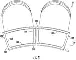
- the aft frame may have an inner portion 102 and an outer portion 104, with a pair of opposing side portions 106 and 108 that extend radially between the inner and the outer portions 102 and 104.
- an inner seal 200 and an outer seal 300 respectively disposed on the inner portion 102 and outer portion 104 of each aft frame 100.
- inner seal 200 and outer seal 300 are circumferentially oriented, each inner seal 200 is circumferentially aligned with the other inner seal 200 on the adjacent aft frame 100, and each outer seal 300 is circumferentially aligned with the other outer seal 300 on the adjacent aft frame 100.
- the aft frame 100 may also include radially-extending side portions 106 and 108, the intersections of side portions 106 and 108 with inner portion 102 define inner corners 120 and 122, and the intersections of side portions 106 and 108 with outer portion 104 define outer corners 130 and 132.
- a radially oriented side seal 400 (see, e.g., FIG.
- aft frame 100 and seals 200, 300, and 400 are disposed between the aft frames 100 and the inner and outer seals 200 and 300 disposed thereon.
- certain features of the aft frame 100 and seals, 200, 300, and 400 will be described with reference to one or both inner corners 120 and 122, nonetheless, it should be recognized by one of ordinary skill in the art that such features can be associated with any or all of inner corners 120, 122 or outer corners 130, 132.
- FIG. 4 illustrates an exemplary circumferentially-oriented seal, which in some embodiments such as the example illustrated in FIG. 4 , may be an inner seal 200, comprising a forward surface 202 and an aft surface 204.
- a projection 206 may be provided on the forward surface 202, the projection 206 extending forward away from the inner seal 200 along the axial direction.
- a wing 208 may be provided at a radially outer portion of the projection 206. As illustrated in FIG.
- the wing 208 may extend radially inward at an oblique angle, e.g., the wing 208 may extend from the projection 206 predominantly along the radial direction but at an angle that is oblique to the true radial direction such that the wing 208 extends along a direction with a relatively small circumferential component.
- the circumferentially-oriented seal may also or instead be an outer seal 300 with similar features. Additionally, predictable variations may be incorporated in such alternative embodiments, such as but not limited to providing an outer seal 300 with wings that may extend in an essentially outward radial direction.
- Circumferentially-oriented seals 200 and 300 such as for example inner seal 200 illustrated in FIG 4 .
- inner seal 200 may be composed primarily of a cloth 210, which can be a woven mesh cloth of a suitable metal material, e.g., alloy L605.
- inner seal 200 can include shims 214 and an elongate backing bar 216 to form a main body 218 of the inner seal 200.
- the materials of the main body 218 are layered, e.g., with the cloth 210 sandwiched between shims 214, as such, main body 218 may be considered as a layered main body or laminated main body. Further illustrated in the example embodiment of FIG.
- a cloth extension 212 can be provided which extends beyond the shims 214 and backing bar 216 in the circumferential direction.
- the cloth extension 212 allows the inner seal 200 to interact (e.g., overlap) with an inner seal 200 on an adjacent aft frame 100 while also maintaining sufficient clearance between the layered main bodies 218 for installation of each inner seal 200.
- the projection 206 may be located at an end of the backing bar 216.
- the projection 206 may define or coincide with a demarcation between main body 218 and cloth extension 212, such that wing 208 and cloth extension 212 are generally disposed in the same circumferential area. That is, although wing 208 and cloth extension 212 are not necessarily circumferentially coextensive, they may originate at about the same location along the circumferential direction while being axially adjacent (see, e.g., FIG. 8 ).
- the side seal 400 may include a forward surface 402 and an aft surface 404, and further may have a projection 406 that extends aft along the axial direction from the aft surface 404, with wings 408 extending radially outward from a radially inner portion of projection 406. Further illustrated in FIG. 5 , in some embodiments wings 408 extend from projection 406 at an oblique angle, e.g., at an angle that is oblique to the true radial direction such that each wing 408 extends along a direction that is predominantly radial with a relatively small circumferential component.
- FIG. 6 an exemplary pair of circumferentially adjacent aft frames 100 are illustrated with inner seals 200 disposed on inner portions 102 of the aft frames 100 and particular aspects of this exemplary embodiment are shown near inner corners 120 and 122 of the aft frames 100.
- the side seal 400 itself is not shown for sake of clarity in FIG. 6.
- FIG. 6
- FIG. 6 illustrates the interfacing relationship of wings 408 on the side seal projection 406 with the wing 208 of one of the inner seals 200, wherein wing 408 on the side seal 400 sealingly engages with the wing 208 on the inner seal 200 (a second wing 208 on the next adjacent inner seal 200 may also be provided, in which case the second wing 208 would essentially mirror the first wing 208 and would interface and sealingly engage with the other side seal wing 408).
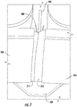
- FIG. 7 illustrates a position of side seal 400 and in particular projection 406 thereon according to some exemplary embodiments when the disclosed sealing arrangement is nearly fully assembled. That is, the illustrated exemplary embodiment is shown in a position where the adjacent inner seals 200 are in place and positioned such that the cloth extensions 212 thereof overlap one another, while side seal 400 has not been fully inserted between inner seals 200 but is displaced outward along the radial direction from its fully installed position. As illustrated in FIG. 7 , cloth extensions 212 can overlap to substantially occlude the circumferential gap between adjacent inner seals 200. It can also be seen in the illustrated example of FIG.
- the projection 406 of side seal 400 and the wings 408 extending from the projection 406 can be disposed forward of the inner seals 200 and in particular the cloth extensions 212 of the inner seals 200, to substantially close off an axial gap between side seal 400 and inner seals 200 when the sealing arrangement is fully assembled.
- FIG. 8 illustrates a radially outward-facing view of an exemplary sealing arrangement wherein side seal wings 408 interface with opposing wings 208 on each of a pair of circumferentially adjacent inner seals 200.
- Wings 408 can sealingly engage wings 208 to occlude flow of working fluid (e.g., compressed air 26) in a radial direction, while the overlapping cloth extensions 212 can prevent or limit bypass flow, i.e., working fluid 26 is prevented or limited from circumventing the wings 208 and 408 by passing over the wings 208 and 408.
- working fluid e.g., compressed air 26
- the pressure of compressed working fluid 26 energizes wings 208 and 408, i.e., the pressure biases inner seal wings 208 radially outward into sealing engagement with side seal wings 408.
- wings 208 and 408 i.e., the pressure biases inner seal wings 208 radially outward into sealing engagement with side seal wings 408.
- various embodiments may include predictable variations of the angle of the wings 208 and/or 408, it is advantageous for the wings 208 and/or 408 to be arranged so as to be energized by compressor flow 26.
- FIG. 9 illustrates exemplary inner seal projections 206 and wings 208 in relation to exemplary side seal projection 406 and wings 408.
- the projections 206, 406 and wings 208, 408 are depicted in isolation (i.e., other elements of side seal 400 and inner seals 200 are omitted) in FIG. 9 for clarity of illustration.
- the exemplary components depicted in FIG. 9 are oriented such that the axial direction is vertical in the illustration of FIG. 9 .
- the exemplary projections 206, 406 and wings 208, 408 of FIG. 9 may be usable with inner seals 200 and side seal 400 such as for example, those illustrated in FIG.
- axial and circumferential gaps that remain when existing seals are used can be obstructed by the projections and wings while preserving installation tolerances, such as clearance between the more rigid portions of the circumferential seals. Obstructing these gaps results in a reduction in non-chargeable flow and better engine performance can be achieved.
- the improved sealing arrangement can be implemented without modifying other components such as the aft frames or stage one nozzle. Thus, existing engines can be retrofitted with the improved seals at relatively low cost.
Landscapes
- Engineering & Computer Science (AREA)
- Mechanical Engineering (AREA)
- General Engineering & Computer Science (AREA)
- Chemical & Material Sciences (AREA)
- Combustion & Propulsion (AREA)
- Turbine Rotor Nozzle Sealing (AREA)
- Gasket Seals (AREA)
Claims (15)
- Dichtungsanordnung zum Abdichten zwischen einer Düse der ersten Stufe und einer Vielzahl von hinteren Rahmen (100) auf einem Übergangskanal einer Turbine, wobei die Turbine eine Mittelachse, eine radiale Richtung senkrecht zur Mittelachse und eine Umfangsrichtung aufweist, die sich um die Mittelachse erstreckt, wobei die Anordnung Folgendes umfasst:eine erste Dichtung (200), die in Umfangsrichtung ausgerichtet ist, wobei die erste Dichtung (200) eine vordere Oberfläche (202), eine hintere Oberfläche (204) und einen Flügel (208) umfasst, der sich radial nach innen in einem schrägen Winkel zur radialen Richtung erstreckt;eine zweite Dichtung (200), die in Umfangsrichtung angrenzend an die erste Dichtung (200) ausgerichtet ist, wobei die zweite Dichtung (200) eine vordere Oberfläche (202), eine hintere Oberfläche (204) und einen Flügel (208) umfasst, der sich radial nach innen in einem schrägen Winkel zur radialen Richtung erstreckt, wobei die zweite Dichtung (200) radial und axial mit der ersten Dichtung (200) ausgerichtet ist, wobei der Flügel (208) der zweiten Dichtung (200) dem Flügel (208) der ersten Dichtung (200) gegenüberliegt und in Umfangsrichtung von dem Flügel (208) der ersten Dichtung (200) beabstandet ist; undeine radial ausgerichtete Seitendichtung (400), die zwischen der ersten Dichtung (200) und der zweiten Dichtung (200) angeordnet ist;dadurch gekennzeichnet, dass die Seitendichtung (400) eine vordere Fläche (402) und eine hintere Fläche (404), einen ersten Flügel (408), der sich radial nach außen in einem schrägen Winkel zur radialen Richtung erstreckt, und einen zweiten Flügel (408), der sich radial nach außen in einem schrägen Winkel zur radialen Richtung erstreckt, umfasst;wobei der erste Flügel (408) der Seitendichtung (400) dichtend mit dem Flügel (208) der ersten Dichtung (200) und der zweite Flügel (408) der Seitendichtung (400) dichtend mit dem Flügel (208) der zweiten Dichtung (200) verbunden ist.
- Dichtungsanordnung nach Anspruch 1, wobei die erste Dichtung (200) eine erste Gewebeverlängerung (212) umfasst, die sich in Umfangsrichtung über den Flügel (208) der ersten Dichtung (200) hinaus erstreckt, und die zweite Dichtung (200) eine zweite Gewebeverlängerung (212) umfasst, die sich in Umfangsrichtung über den Flügel (208) der zweiten Dichtung (200) hinaus erstreckt.
- Dichtungsanordnung nach Anspruch 2, wobei die erste Dichtung (200) ein Gewebematerial (210) und eine oder mehrere Scheiben (214) umfasst, wobei die erste Gewebeverlängerung (212) an das Gewebematerial (210) angrenzt und sich in Umfangsrichtung über die eine oder die mehreren Scheiben hinaus erstreckt, und wobei die zweite Dichtung ein Gewebematerial und eine oder mehrere Scheiben (214) umfasst, wobei die zweite Gewebeverlängerung (212) an das Gewebematerial (210) der zweiten Dichtung (200) angrenzt und sich in Umfangsrichtung über die eine oder mehreren Scheiben (214) der zweiten Dichtung (200) hinaus erstreckt.
- Dichtungsanordnung nach Anspruch 3, wobei die erste Dichtung (200) ferner eine erste längliche Stützstange (216) entlang der vorderen Oberfläche und einen Vorsprung (206) umfasst, der sich axial von der vorderen Oberfläche (202) an einem Ende der ersten Stützstange (216) nach vorne erstreckt, wobei sich der Flügel (208) der ersten Dichtung (200) von einem äußeren Abschnitt des Vorsprungs (206) der ersten Dichtung (200) erstreckt, und wobei die zweite Dichtung (200) ferner eine zweite längliche Stützstange (216) entlang der vorderen Oberfläche (202) der zweiten Dichtung (200) und einen Vorsprung (206) umfasst, der sich axial von der vorderen Oberfläche (202) der zweiten Dichtung (200) an einem Ende der zweiten Stützstange (216) nach vorne erstreckt, wobei sich der Flügel (208) der zweiten Dichtung (200) von einem äußeren Abschnitt des Vorsprungs (206) der zweiten Dichtung (200) erstreckt.
- Dichtungsanordnung nach Anspruch 4, wobei sich die erste Gewebeverlängerung (212) in Umfangsrichtung über den Flügel (208) der ersten Dichtung (200) hinaus erstreckt und sich die zweite Gewebeverlängerung (212) in Umfangsrichtung über den Flügel (208) der zweiten Dichtung (200) hinaus erstreckt, sodass sich die erste Gewebeverlängerung (212) und die zweite Gewebeverlängerung (212) hinter dem Flügel (208) der ersten Dichtung (200) und dem Flügel (208) der zweiten Dichtung (200) überlappen.
- Dichtungsanordnung nach Anspruch 1, wobei die erste Dichtung (200) ferner einen Vorsprung (206) umfasst, der sich axial von der vorderen Oberfläche (202) nach vorne erstreckt, wobei sich der Flügel (208) der ersten Dichtung (200) von einem äußeren Abschnitt des Vorsprungs (206) der ersten Dichtung (200) erstreckt, und wobei die zweite Dichtung (200) ferner einen Vorsprung (206) umfasst, der sich axial von der vorderen Oberfläche (202) nach vorne erstreckt, wobei sich der Flügel (208) der zweiten Dichtung (200) von einem äußeren Abschnitt des Vorsprungs (206) der zweiten Dichtung (200) erstreckt.
- Dichtungsanordnung nach einem vorhergehenden Anspruch, wobei die Seitendichtung (400) ferner einen Vorsprung (406) auf der hinteren Fläche (404) der Seitendichtung (400) umfasst, der Vorsprung (406) sich axial von der hinteren Fläche (404) der Seitendichtung (400) nach hinten erstreckt und eine erste Fläche, die eine axiale Breite und eine radiale Höhe definiert, und eine zweite Fläche, die der ersten Fläche gegenüberliegt und in Umfangsrichtung von der ersten Fläche beabstandet ist, umfasst, wobei die zweite Fläche eine axiale Breite und eine radiale Höhe definiert, wobei sich der erste Flügel (408) von einem inneren Abschnitt der ersten Fläche erstreckt und sich der zweite Flügel (408) von einem inneren Abschnitt der zweiten Fläche erstreckt.
- Gasturbine (10), umfassend:einen Verdichter (14);eine Turbine (18) mit einer Mittelachse, einer radialen Richtung senkrecht zur Mittelachse und einer Umfangsrichtung, die sich um die Achse erstreckt; undeine Vielzahl von Brennkammern (16), die stromabwärts vom Verdichter (14) und stromaufwärts von der Turbine (18) angeordnet sind, wobei die Brennkammern (16) in Umfangsrichtung um eine Mittelachse (A) der Turbine (18) herum in Abständen angeordnet sind, wobei jede Brennkammer (16) Folgendes umfasst:ein stromaufwärtiges Ende;ein stromabwärtiges Ende;einen Übergangskanal (32), der einen Strömungsweg (P) vom Verdichter (16) zur Turbine (18) definiert;einen hinteren Rahmen (100), der das stromabwärtige Ende des Übergangskanals (32) in Umfangsrichtung umgibt, wobei der hintere Rahmen (100) einen inneren Abschnitt (102), der radial von einem äußeren Abschnitt (104) getrennt ist, und ein Paar gegenüberliegender Seitenabschnitte (106, 108) umfasst, die sich radial zwischen dem inneren Abschnitt (102) und dem äußeren Abschnitt (104) erstrecken;eine erste innere Dichtung (200), die auf dem inneren Abschnitt (102) eines ersten aus der Vielzahl der hinteren Rahmen (100) der Brennkammern angeordnet ist;eine zweite innere Dichtung (200), die auf dem inneren Abschnitt (102) eines in Umfangsrichtung an den ersten aus der Vielzahl der hinteren Rahmen (100) der Brennkammern angrenzenden hinteren Rahmens (100) der Brennkammern angeordnet ist; undeine radial ausgerichtete Seitendichtung (400), die zwischen der ersten inneren Dichtung (200) und der zweiten inneren Dichtung (200) angeordnet ist;dadurch gekennzeichnet, dass die erste innere Dichtung (200) eine vordere Oberfläche (202), eine hintere Oberfläche (204) und einen ersten Flügel (208) umfasst, der sich radial in einem schrägen Winkel zur radialen Richtung nach innen erstreckt;wobei die zweite innere Dichtung (200) eine vordere Oberfläche (202), eine hintere Oberfläche (204) und einen zweiten Flügel (208) umfasst, der sich radial in einem schrägen Winkel zur radialen Richtung nach innen erstreckt, wobei die zweite innere Dichtung (200) radial und axial mit der ersten inneren Dichtung (200) ausgerichtet ist, wobei der zweite Flügel (208) dem ersten Flügel (208) gegenüberliegt und in Umfangsrichtung von diesem beabstandet ist;wobei die Seitendichtung (400) eine vordere Fläche (402) und eine hintere Fläche (404), einen dritten Flügel (408), der sich radial in einem schrägen Winkel zur radialen Richtung nach außen erstreckt, und einen vierten Flügel (408), der sich radial in einem schrägen Winkel zur radialen Richtung nach außen erstreckt, umfasst;wobei der dritte Flügel (408) dichtend mit dem ersten Flügel (208) und der vierte Flügel (408) dichtend mit dem zweiten Flügel (208) verbunden ist.
- Gasturbine nach Anspruch 8, wobei die erste innere Dichtung (200) ein Gewebematerial (210), eine oder mehrere Scheiben (214) und eine erste Gewebeverlängerung (212) umfasst, die an das Gewebematerial (210) angrenzt und sich in Umfangsrichtung über die eine oder mehreren Scheiben (214) hinaus erstreckt; und die zweite innere Dichtung (200) ein Gewebematerial (210), eine oder mehrere Scheiben (214) und eine zweite Gewebeverlängerung (212) umfasst, wobei die zweite Gewebeverlängerung (212) an das Gewebematerial (210) der zweiten Dichtung (200) angrenzt und sich in Umfangsrichtung über die eine oder mehreren Scheiben (214) der zweiten Dichtung (200) hinaus erstreckt.
- Gasturbine nach Anspruch 9, wobei die erste innere Dichtung (200) ferner eine erste längliche Stützstange (216) entlang der vorderen Oberfläche (202) der ersten inneren Dichtung (200) und einen ersten Vorsprung (206) umfasst, der sich axial von der vorderen Oberfläche (202) der ersten inneren Dichtung (200) an einem Ende der ersten Stützstange (216) nach vorne erstreckt, wobei sich der erste Flügel (208) von einem äußeren Abschnitt des ersten Vorsprungs (206) erstreckt, und wobei die zweite innere Dichtung (200) ferner eine zweite längliche Stützstange (216) entlang der vorderen Oberfläche (202) der zweiten inneren Dichtung (200) und einen zweiten Vorsprung (206) umfasst, der sich axial von der vorderen Oberfläche (202) der zweiten inneren Dichtung (200) an einem Ende der zweiten Stützstange (216) nach vorne erstreckt, wobei sich der zweite Flügel (208) von einem äußeren Abschnitt des zweiten Vorsprungs (206) erstreckt.
- Gasturbine nach Anspruch 10, wobei die Seitendichtung (400) ferner einen Vorsprung (406) auf der hinteren Fläche (404) der Seitendichtung (400) umfasst, wobei sich der Vorsprung (406) axial von der hinteren Fläche (404) der Seitendichtung (400) nach hinten erstreckt, wobei sich der dritte Flügel (408) von einem inneren Abschnitt des Vorsprungs (406) und der vierte Flügel (408) von einem inneren Abschnitt des Vorsprungs (406) erstreckt.
- Gasturbine nach Anspruch 11, wobei der Vorsprung (406) der Seitendichtung (400) ferner eine erste Fläche, die eine axiale Breite und eine radiale Höhe definiert, und eine zweite Fläche, die der ersten Fläche gegenüberliegt und in Umfangsrichtung von der ersten Fläche beabstandet ist, umfasst, wobei die zweite Fläche eine axiale Breite und eine radiale Höhe definiert, wobei sich der dritte Flügel (408) von einem inneren Abschnitt der ersten Fläche und der vierte Flügel (408) von einem inneren Abschnitt der zweiten Fläche erstreckt.
- Gasturbine nach Anspruch 12, wobei sich die erste Gewebeverlängerung (212) in Umfangsrichtung über den ersten Flügel (208) hinaus erstreckt und sich die zweite Gewebeverlängerung (212) in Umfangsrichtung über den zweiten Flügel (208) hinaus erstreckt, sodass sich die erste Gewebeverlängerung (212) und die zweite Gewebeverlängerung (212) überlappen.
- Gasturbine nach Anspruch 13, wobei der Vorsprung (406) der Seitendichtung (400) axial mit dem ersten und zweiten Vorsprung (206) ausgerichtet ist, wobei sich die erste und zweite Gewebeverlängerung (212) axial dahinter überlappen.
- Gasturbine nach Anspruch 14, wobei der erste, zweite, dritte und vierte Flügel (208, 408) in einem radialen Strömungsweg aus komprimiertem Arbeitsfluid (26) angeordnet sind, um den ersten und dritten Flügel (208, 408) durch radiale Strömung des komprimierten Arbeitsfluids (26) in Dichtungseingriff zu bringen und den zweiten und vierten Flügel (208, 408) durch radiale Strömung des komprimierten Arbeitsfluids (26) in Dichtungseingriff zu bringen.
Applications Claiming Priority (1)
| Application Number | Priority Date | Filing Date | Title |
|---|---|---|---|
| US15/254,037 US10508602B2 (en) | 2016-09-01 | 2016-09-01 | Corner flow reduction seals |
Publications (2)
| Publication Number | Publication Date |
|---|---|
| EP3290641A1 EP3290641A1 (de) | 2018-03-07 |
| EP3290641B1 true EP3290641B1 (de) | 2019-10-23 |
Family
ID=59702598
Family Applications (1)
| Application Number | Title | Priority Date | Filing Date |
|---|---|---|---|
| EP17187889.5A Active EP3290641B1 (de) | 2016-09-01 | 2017-08-25 | Eckflussreduzierungsdichtungen |
Country Status (3)
| Country | Link |
|---|---|
| US (1) | US10508602B2 (de) |
| EP (1) | EP3290641B1 (de) |
| JP (1) | JP6907069B2 (de) |
Families Citing this family (17)
| Publication number | Priority date | Publication date | Assignee | Title |
|---|---|---|---|---|
| US10690059B2 (en) | 2016-09-26 | 2020-06-23 | General Electric Company | Advanced seals with reduced corner leakage |
| JP7149807B2 (ja) * | 2018-11-01 | 2022-10-07 | 三菱重工業株式会社 | ガスタービン燃焼器 |
| JP6737969B1 (ja) | 2020-02-18 | 2020-08-12 | 三菱日立パワーシステムズ株式会社 | 出口シール、及びこれを備えるガスタービン |
| US11187152B1 (en) * | 2020-09-30 | 2021-11-30 | General Electric Company | Turbomachine sealing arrangement having a cooling flow director |
| US11608783B2 (en) | 2020-11-04 | 2023-03-21 | Delavan, Inc. | Surface igniter cooling system |
| US11692488B2 (en) | 2020-11-04 | 2023-07-04 | Delavan Inc. | Torch igniter cooling system |
| US11473505B2 (en) | 2020-11-04 | 2022-10-18 | Delavan Inc. | Torch igniter cooling system |
| US11635027B2 (en) | 2020-11-18 | 2023-04-25 | Collins Engine Nozzles, Inc. | Fuel systems for torch ignition devices |
| US11421602B2 (en) | 2020-12-16 | 2022-08-23 | Delavan Inc. | Continuous ignition device exhaust manifold |
| US11486309B2 (en) | 2020-12-17 | 2022-11-01 | Delavan Inc. | Axially oriented internally mounted continuous ignition device: removable hot surface igniter |
| US11635210B2 (en) | 2020-12-17 | 2023-04-25 | Collins Engine Nozzles, Inc. | Conformal and flexible woven heat shields for gas turbine engine components |
| US20220195933A1 (en) * | 2020-12-17 | 2022-06-23 | Delavan Inc. | Radially oriented internally mounted continuous ignition device |
| US12092333B2 (en) * | 2020-12-17 | 2024-09-17 | Collins Engine Nozzles, Inc. | Radially oriented internally mounted continuous ignition device |
| US11754289B2 (en) | 2020-12-17 | 2023-09-12 | Delavan, Inc. | Axially oriented internally mounted continuous ignition device: removable nozzle |
| US11209164B1 (en) | 2020-12-18 | 2021-12-28 | Delavan Inc. | Fuel injector systems for torch igniters |
| US11680528B2 (en) | 2020-12-18 | 2023-06-20 | Delavan Inc. | Internally-mounted torch igniters with removable igniter heads |
| JP6980144B1 (ja) | 2021-03-24 | 2021-12-15 | 三菱パワー株式会社 | ガスタービン用燃焼器、ガスタービン及びガスタービンの組立方法 |
Family Cites Families (28)
| Publication number | Priority date | Publication date | Assignee | Title |
|---|---|---|---|---|
| US5265412A (en) | 1992-07-28 | 1993-11-30 | General Electric Company | Self-accommodating brush seal for gas turbine combustor |
| JPH09195799A (ja) | 1996-01-17 | 1997-07-29 | Mitsubishi Heavy Ind Ltd | 燃焼器のスプリングシール装置 |
| US6450762B1 (en) | 2001-01-31 | 2002-09-17 | General Electric Company | Integral aft seal for turbine applications |
| US20020121744A1 (en) * | 2001-03-05 | 2002-09-05 | General Electric Company | Low leakage flexible cloth seals for turbine combustors |
| US6547257B2 (en) | 2001-05-04 | 2003-04-15 | General Electric Company | Combination transition piece floating cloth seal and stage 1 turbine nozzle flexible sealing element |
| US6588214B2 (en) | 2001-10-09 | 2003-07-08 | Power Systems Mfg, Llc | Wear reduction means for a gas turbine combustor transition duct end frame |
| US6834507B2 (en) | 2002-08-15 | 2004-12-28 | Power Systems Mfg., Llc | Convoluted seal with enhanced wear capability |
| JP4191552B2 (ja) | 2003-07-14 | 2008-12-03 | 三菱重工業株式会社 | ガスタービン尾筒の冷却構造 |
| US7527469B2 (en) | 2004-12-10 | 2009-05-05 | Siemens Energy, Inc. | Transition-to-turbine seal apparatus and kit for transition/turbine junction of a gas turbine engine |
| US7246995B2 (en) | 2004-12-10 | 2007-07-24 | Siemens Power Generation, Inc. | Seal usable between a transition and a turbine vane assembly in a turbine engine |
| JP4476152B2 (ja) | 2005-04-01 | 2010-06-09 | 三菱重工業株式会社 | ガスタービン燃焼器 |
| US7784264B2 (en) | 2006-08-03 | 2010-08-31 | Siemens Energy, Inc. | Slidable spring-loaded transition-to-turbine seal apparatus and heat-shielding system, comprising the seal, at transition/turbine junction of a gas turbine engine |
| US7797948B2 (en) | 2007-03-27 | 2010-09-21 | Siemens Energy, Inc. | Transition-to-turbine seal apparatus and transition-to-turbine seal junction of a gas turbine engine |
| US8104772B2 (en) | 2008-06-27 | 2012-01-31 | Seal Science & Technology, Llc | Gas turbine nozzle seals for 2000° F. gas containment |
| US8118549B2 (en) | 2008-08-26 | 2012-02-21 | Siemens Energy, Inc. | Gas turbine transition duct apparatus |
| FR2937098B1 (fr) | 2008-10-15 | 2015-11-20 | Snecma | Etancheite entre une chambre de combustion et un distributeur de turbine dans une turbomachine |
| US8141879B2 (en) * | 2009-07-20 | 2012-03-27 | General Electric Company | Seals for a turbine engine, and methods of assembling a turbine engine |
| US8322977B2 (en) | 2009-07-22 | 2012-12-04 | Siemens Energy, Inc. | Seal structure for preventing leakage of gases across a gap between two components in a turbine engine |
| US8398090B2 (en) | 2010-06-09 | 2013-03-19 | General Electric Company | Spring loaded seal assembly for turbines |
| US8225614B2 (en) | 2010-10-07 | 2012-07-24 | General Electric Company | Shim for sealing transition pieces |
| US8985592B2 (en) | 2011-02-07 | 2015-03-24 | Siemens Aktiengesellschaft | System for sealing a gap between a transition and a turbine |
| US20120280460A1 (en) | 2011-05-06 | 2012-11-08 | General Electric Company | Two-piece side seal with covers |
| US8562000B2 (en) | 2011-05-20 | 2013-10-22 | Siemens Energy, Inc. | Turbine combustion system transition piece side seals |
| US9115585B2 (en) | 2011-06-06 | 2015-08-25 | General Electric Company | Seal assembly for gas turbine |
| US10161523B2 (en) | 2011-12-23 | 2018-12-25 | General Electric Company | Enhanced cloth seal |
| US9249678B2 (en) | 2012-06-27 | 2016-02-02 | General Electric Company | Transition duct for a gas turbine |
| US9528383B2 (en) | 2013-12-31 | 2016-12-27 | General Electric Company | System for sealing between combustors and turbine of gas turbine engine |
| US10689995B2 (en) | 2016-05-27 | 2020-06-23 | General Electric Company | Side seal with reduced corner leakage |
-
2016
- 2016-09-01 US US15/254,037 patent/US10508602B2/en active Active
-
2017
- 2017-08-18 JP JP2017157726A patent/JP6907069B2/ja active Active
- 2017-08-25 EP EP17187889.5A patent/EP3290641B1/de active Active
Non-Patent Citations (1)
| Title |
|---|
| None * |
Also Published As
| Publication number | Publication date |
|---|---|
| JP6907069B2 (ja) | 2021-07-21 |
| US20180058331A1 (en) | 2018-03-01 |
| EP3290641A1 (de) | 2018-03-07 |
| JP2018059502A (ja) | 2018-04-12 |
| US10508602B2 (en) | 2019-12-17 |
Similar Documents
| Publication | Publication Date | Title |
|---|---|---|
| US10508602B2 (en) | Corner flow reduction seals | |
| US9243508B2 (en) | System and method for recirculating a hot gas flowing through a gas turbine | |
| US9458767B2 (en) | Fuel injection insert for a turbine nozzle segment | |
| US9506374B2 (en) | Component of a turbine with leaf seals and method for sealing against leakage between a vane and a carrier element | |
| EP3299582B1 (de) | Dichtungseinrichtung und gasturbine mit einer dichtungseinrichtung | |
| US20040168443A1 (en) | Methods and apparatus for assembling gas turbine engines | |
| EP3299680B1 (de) | Dichtungsanordnung und zugehörige gasturbine | |
| US20140241857A1 (en) | Flow diverter to redirect secondary flow | |
| US9506366B2 (en) | Helical seal system for a turbomachine | |
| EP2650484A1 (de) | Zwischenstufendichtungsanordnung einer Turbine | |
| EP3249164B1 (de) | Seitendichtung mit reduzierter eckleckage | |
| EP3617458B1 (de) | Ringförmige dichtung eines gasturbinentriebwerks | |
| US10329936B2 (en) | Gas turbine engine aft seal plate geometry | |
| EP3418496B1 (de) | Turbomaschinenrotorschaufel | |
| US11702991B2 (en) | Turbomachine sealing arrangement having a heat shield | |
| EP2557268A2 (de) | System und Verfahren zur Kontrolle der Strömung in einer Strömungsmaschine |
Legal Events
| Date | Code | Title | Description |
|---|---|---|---|
| PUAI | Public reference made under article 153(3) epc to a published international application that has entered the european phase |
Free format text: ORIGINAL CODE: 0009012 |
|
| STAA | Information on the status of an ep patent application or granted ep patent |
Free format text: STATUS: THE APPLICATION HAS BEEN PUBLISHED |
|
| AK | Designated contracting states |
Kind code of ref document: A1 Designated state(s): AL AT BE BG CH CY CZ DE DK EE ES FI FR GB GR HR HU IE IS IT LI LT LU LV MC MK MT NL NO PL PT RO RS SE SI SK SM TR |
|
| AX | Request for extension of the european patent |
Extension state: BA ME |
|
| STAA | Information on the status of an ep patent application or granted ep patent |
Free format text: STATUS: REQUEST FOR EXAMINATION WAS MADE |
|
| 17P | Request for examination filed |
Effective date: 20180907 |
|
| RBV | Designated contracting states (corrected) |
Designated state(s): AL AT BE BG CH CY CZ DE DK EE ES FI FR GB GR HR HU IE IS IT LI LT LU LV MC MK MT NL NO PL PT RO RS SE SI SK SM TR |
|
| GRAJ | Information related to disapproval of communication of intention to grant by the applicant or resumption of examination proceedings by the epo deleted |
Free format text: ORIGINAL CODE: EPIDOSDIGR1 |
|
| STAA | Information on the status of an ep patent application or granted ep patent |
Free format text: STATUS: GRANT OF PATENT IS INTENDED |
|
| GRAP | Despatch of communication of intention to grant a patent |
Free format text: ORIGINAL CODE: EPIDOSNIGR1 |
|
| INTG | Intention to grant announced |
Effective date: 20190424 |
|
| RIN1 | Information on inventor provided before grant (corrected) |
Inventor name: BARTON, JESSE ELLIS Inventor name: MONAGHAN, ELIZABETH ANGELYN Inventor name: DICINTIO, RICHARD MARTIN |
|
| GRAS | Grant fee paid |
Free format text: ORIGINAL CODE: EPIDOSNIGR3 |
|
| GRAA | (expected) grant |
Free format text: ORIGINAL CODE: 0009210 |
|
| STAA | Information on the status of an ep patent application or granted ep patent |
Free format text: STATUS: THE PATENT HAS BEEN GRANTED |
|
| AK | Designated contracting states |
Kind code of ref document: B1 Designated state(s): AL AT BE BG CH CY CZ DE DK EE ES FI FR GB GR HR HU IE IS IT LI LT LU LV MC MK MT NL NO PL PT RO RS SE SI SK SM TR |
|
| REG | Reference to a national code |
Ref country code: GB Ref legal event code: FG4D |
|
| REG | Reference to a national code |
Ref country code: CH Ref legal event code: EP |
|
| REG | Reference to a national code |
Ref country code: IE Ref legal event code: FG4D |
|
| REG | Reference to a national code |
Ref country code: DE Ref legal event code: R096 Ref document number: 602017008001 Country of ref document: DE |
|
| REG | Reference to a national code |
Ref country code: AT Ref legal event code: REF Ref document number: 1193856 Country of ref document: AT Kind code of ref document: T Effective date: 20191115 |
|
| REG | Reference to a national code |
Ref country code: NL Ref legal event code: MP Effective date: 20191023 |
|
| REG | Reference to a national code |
Ref country code: LT Ref legal event code: MG4D |
|
| PG25 | Lapsed in a contracting state [announced via postgrant information from national office to epo] |
Ref country code: FI Free format text: LAPSE BECAUSE OF FAILURE TO SUBMIT A TRANSLATION OF THE DESCRIPTION OR TO PAY THE FEE WITHIN THE PRESCRIBED TIME-LIMIT Effective date: 20191023 Ref country code: BG Free format text: LAPSE BECAUSE OF FAILURE TO SUBMIT A TRANSLATION OF THE DESCRIPTION OR TO PAY THE FEE WITHIN THE PRESCRIBED TIME-LIMIT Effective date: 20200123 Ref country code: LT Free format text: LAPSE BECAUSE OF FAILURE TO SUBMIT A TRANSLATION OF THE DESCRIPTION OR TO PAY THE FEE WITHIN THE PRESCRIBED TIME-LIMIT Effective date: 20191023 Ref country code: PT Free format text: LAPSE BECAUSE OF FAILURE TO SUBMIT A TRANSLATION OF THE DESCRIPTION OR TO PAY THE FEE WITHIN THE PRESCRIBED TIME-LIMIT Effective date: 20200224 Ref country code: PL Free format text: LAPSE BECAUSE OF FAILURE TO SUBMIT A TRANSLATION OF THE DESCRIPTION OR TO PAY THE FEE WITHIN THE PRESCRIBED TIME-LIMIT Effective date: 20191023 Ref country code: GR Free format text: LAPSE BECAUSE OF FAILURE TO SUBMIT A TRANSLATION OF THE DESCRIPTION OR TO PAY THE FEE WITHIN THE PRESCRIBED TIME-LIMIT Effective date: 20200124 Ref country code: SE Free format text: LAPSE BECAUSE OF FAILURE TO SUBMIT A TRANSLATION OF THE DESCRIPTION OR TO PAY THE FEE WITHIN THE PRESCRIBED TIME-LIMIT Effective date: 20191023 Ref country code: NO Free format text: LAPSE BECAUSE OF FAILURE TO SUBMIT A TRANSLATION OF THE DESCRIPTION OR TO PAY THE FEE WITHIN THE PRESCRIBED TIME-LIMIT Effective date: 20200123 Ref country code: LV Free format text: LAPSE BECAUSE OF FAILURE TO SUBMIT A TRANSLATION OF THE DESCRIPTION OR TO PAY THE FEE WITHIN THE PRESCRIBED TIME-LIMIT Effective date: 20191023 Ref country code: NL Free format text: LAPSE BECAUSE OF FAILURE TO SUBMIT A TRANSLATION OF THE DESCRIPTION OR TO PAY THE FEE WITHIN THE PRESCRIBED TIME-LIMIT Effective date: 20191023 |
|
| PG25 | Lapsed in a contracting state [announced via postgrant information from national office to epo] |
Ref country code: RS Free format text: LAPSE BECAUSE OF FAILURE TO SUBMIT A TRANSLATION OF THE DESCRIPTION OR TO PAY THE FEE WITHIN THE PRESCRIBED TIME-LIMIT Effective date: 20191023 Ref country code: IS Free format text: LAPSE BECAUSE OF FAILURE TO SUBMIT A TRANSLATION OF THE DESCRIPTION OR TO PAY THE FEE WITHIN THE PRESCRIBED TIME-LIMIT Effective date: 20200224 Ref country code: HR Free format text: LAPSE BECAUSE OF FAILURE TO SUBMIT A TRANSLATION OF THE DESCRIPTION OR TO PAY THE FEE WITHIN THE PRESCRIBED TIME-LIMIT Effective date: 20191023 |
|
| PG25 | Lapsed in a contracting state [announced via postgrant information from national office to epo] |
Ref country code: AL Free format text: LAPSE BECAUSE OF FAILURE TO SUBMIT A TRANSLATION OF THE DESCRIPTION OR TO PAY THE FEE WITHIN THE PRESCRIBED TIME-LIMIT Effective date: 20191023 |
|
| REG | Reference to a national code |
Ref country code: DE Ref legal event code: R097 Ref document number: 602017008001 Country of ref document: DE |
|
| PG2D | Information on lapse in contracting state deleted |
Ref country code: IS |
|
| PG25 | Lapsed in a contracting state [announced via postgrant information from national office to epo] |
Ref country code: ES Free format text: LAPSE BECAUSE OF FAILURE TO SUBMIT A TRANSLATION OF THE DESCRIPTION OR TO PAY THE FEE WITHIN THE PRESCRIBED TIME-LIMIT Effective date: 20191023 Ref country code: EE Free format text: LAPSE BECAUSE OF FAILURE TO SUBMIT A TRANSLATION OF THE DESCRIPTION OR TO PAY THE FEE WITHIN THE PRESCRIBED TIME-LIMIT Effective date: 20191023 Ref country code: DK Free format text: LAPSE BECAUSE OF FAILURE TO SUBMIT A TRANSLATION OF THE DESCRIPTION OR TO PAY THE FEE WITHIN THE PRESCRIBED TIME-LIMIT Effective date: 20191023 Ref country code: CZ Free format text: LAPSE BECAUSE OF FAILURE TO SUBMIT A TRANSLATION OF THE DESCRIPTION OR TO PAY THE FEE WITHIN THE PRESCRIBED TIME-LIMIT Effective date: 20191023 Ref country code: RO Free format text: LAPSE BECAUSE OF FAILURE TO SUBMIT A TRANSLATION OF THE DESCRIPTION OR TO PAY THE FEE WITHIN THE PRESCRIBED TIME-LIMIT Effective date: 20191023 Ref country code: IS Free format text: LAPSE BECAUSE OF FAILURE TO SUBMIT A TRANSLATION OF THE DESCRIPTION OR TO PAY THE FEE WITHIN THE PRESCRIBED TIME-LIMIT Effective date: 20200223 |
|
| REG | Reference to a national code |
Ref country code: AT Ref legal event code: MK05 Ref document number: 1193856 Country of ref document: AT Kind code of ref document: T Effective date: 20191023 |
|
| PLBE | No opposition filed within time limit |
Free format text: ORIGINAL CODE: 0009261 |
|
| STAA | Information on the status of an ep patent application or granted ep patent |
Free format text: STATUS: NO OPPOSITION FILED WITHIN TIME LIMIT |
|
| PG25 | Lapsed in a contracting state [announced via postgrant information from national office to epo] |
Ref country code: IT Free format text: LAPSE BECAUSE OF FAILURE TO SUBMIT A TRANSLATION OF THE DESCRIPTION OR TO PAY THE FEE WITHIN THE PRESCRIBED TIME-LIMIT Effective date: 20191023 Ref country code: SM Free format text: LAPSE BECAUSE OF FAILURE TO SUBMIT A TRANSLATION OF THE DESCRIPTION OR TO PAY THE FEE WITHIN THE PRESCRIBED TIME-LIMIT Effective date: 20191023 Ref country code: SK Free format text: LAPSE BECAUSE OF FAILURE TO SUBMIT A TRANSLATION OF THE DESCRIPTION OR TO PAY THE FEE WITHIN THE PRESCRIBED TIME-LIMIT Effective date: 20191023 |
|
| 26N | No opposition filed |
Effective date: 20200724 |
|
| PG25 | Lapsed in a contracting state [announced via postgrant information from national office to epo] |
Ref country code: AT Free format text: LAPSE BECAUSE OF FAILURE TO SUBMIT A TRANSLATION OF THE DESCRIPTION OR TO PAY THE FEE WITHIN THE PRESCRIBED TIME-LIMIT Effective date: 20191023 Ref country code: SI Free format text: LAPSE BECAUSE OF FAILURE TO SUBMIT A TRANSLATION OF THE DESCRIPTION OR TO PAY THE FEE WITHIN THE PRESCRIBED TIME-LIMIT Effective date: 20191023 |
|
| PG25 | Lapsed in a contracting state [announced via postgrant information from national office to epo] |
Ref country code: MC Free format text: LAPSE BECAUSE OF FAILURE TO SUBMIT A TRANSLATION OF THE DESCRIPTION OR TO PAY THE FEE WITHIN THE PRESCRIBED TIME-LIMIT Effective date: 20191023 |
|
| REG | Reference to a national code |
Ref country code: CH Ref legal event code: PL |
|
| PG25 | Lapsed in a contracting state [announced via postgrant information from national office to epo] |
Ref country code: LU Free format text: LAPSE BECAUSE OF NON-PAYMENT OF DUE FEES Effective date: 20200825 Ref country code: LI Free format text: LAPSE BECAUSE OF NON-PAYMENT OF DUE FEES Effective date: 20200831 Ref country code: CH Free format text: LAPSE BECAUSE OF NON-PAYMENT OF DUE FEES Effective date: 20200831 |
|
| REG | Reference to a national code |
Ref country code: BE Ref legal event code: MM Effective date: 20200831 |
|
| PG25 | Lapsed in a contracting state [announced via postgrant information from national office to epo] |
Ref country code: FR Free format text: LAPSE BECAUSE OF NON-PAYMENT OF DUE FEES Effective date: 20200831 |
|
| PG25 | Lapsed in a contracting state [announced via postgrant information from national office to epo] |
Ref country code: BE Free format text: LAPSE BECAUSE OF NON-PAYMENT OF DUE FEES Effective date: 20200831 Ref country code: IE Free format text: LAPSE BECAUSE OF NON-PAYMENT OF DUE FEES Effective date: 20200825 |
|
| GBPC | Gb: european patent ceased through non-payment of renewal fee |
Effective date: 20210825 |
|
| PG25 | Lapsed in a contracting state [announced via postgrant information from national office to epo] |
Ref country code: TR Free format text: LAPSE BECAUSE OF FAILURE TO SUBMIT A TRANSLATION OF THE DESCRIPTION OR TO PAY THE FEE WITHIN THE PRESCRIBED TIME-LIMIT Effective date: 20191023 Ref country code: MT Free format text: LAPSE BECAUSE OF FAILURE TO SUBMIT A TRANSLATION OF THE DESCRIPTION OR TO PAY THE FEE WITHIN THE PRESCRIBED TIME-LIMIT Effective date: 20191023 Ref country code: CY Free format text: LAPSE BECAUSE OF FAILURE TO SUBMIT A TRANSLATION OF THE DESCRIPTION OR TO PAY THE FEE WITHIN THE PRESCRIBED TIME-LIMIT Effective date: 20191023 |
|
| PG25 | Lapsed in a contracting state [announced via postgrant information from national office to epo] |
Ref country code: MK Free format text: LAPSE BECAUSE OF FAILURE TO SUBMIT A TRANSLATION OF THE DESCRIPTION OR TO PAY THE FEE WITHIN THE PRESCRIBED TIME-LIMIT Effective date: 20191023 |
|
| PG25 | Lapsed in a contracting state [announced via postgrant information from national office to epo] |
Ref country code: GB Free format text: LAPSE BECAUSE OF NON-PAYMENT OF DUE FEES Effective date: 20210825 |
|
| REG | Reference to a national code |
Ref country code: DE Ref legal event code: R082 Ref document number: 602017008001 Country of ref document: DE Ref country code: DE Ref legal event code: R081 Ref document number: 602017008001 Country of ref document: DE Owner name: GENERAL ELECTRIC TECHNOLOGY GMBH, CH Free format text: FORMER OWNER: GENERAL ELECTRIC COMPANY, SCHENECTADY, NY, US |
|
| PGFP | Annual fee paid to national office [announced via postgrant information from national office to epo] |
Ref country code: DE Payment date: 20250724 Year of fee payment: 9 |