EP3299198A1 - Shutter device for closing a ventilation duct - Google Patents
Shutter device for closing a ventilation duct Download PDFInfo
- Publication number
- EP3299198A1 EP3299198A1 EP17306153.2A EP17306153A EP3299198A1 EP 3299198 A1 EP3299198 A1 EP 3299198A1 EP 17306153 A EP17306153 A EP 17306153A EP 3299198 A1 EP3299198 A1 EP 3299198A1
- Authority
- EP
- European Patent Office
- Prior art keywords
- duct
- flap
- shutter
- axis
- passage
- Prior art date
- Legal status (The legal status is an assumption and is not a legal conclusion. Google has not performed a legal analysis and makes no representation as to the accuracy of the status listed.)
- Granted
Links
Images


Classifications
-
- B—PERFORMING OPERATIONS; TRANSPORTING
- B60—VEHICLES IN GENERAL
- B60H—ARRANGEMENTS OF HEATING, COOLING, VENTILATING OR OTHER AIR-TREATING DEVICES SPECIALLY ADAPTED FOR PASSENGER OR GOODS SPACES OF VEHICLES
- B60H1/00—Heating, cooling or ventilating [HVAC] devices
- B60H1/34—Nozzles; Air-diffusers
- B60H1/3414—Nozzles; Air-diffusers with means for adjusting the air stream direction
- B60H1/3421—Nozzles; Air-diffusers with means for adjusting the air stream direction using only pivoting shutters
-
- B—PERFORMING OPERATIONS; TRANSPORTING
- B60—VEHICLES IN GENERAL
- B60H—ARRANGEMENTS OF HEATING, COOLING, VENTILATING OR OTHER AIR-TREATING DEVICES SPECIALLY ADAPTED FOR PASSENGER OR GOODS SPACES OF VEHICLES
- B60H1/00—Heating, cooling or ventilating [HVAC] devices
- B60H1/34—Nozzles; Air-diffusers
- B60H2001/3464—Details of hinges
-
- B—PERFORMING OPERATIONS; TRANSPORTING
- B60—VEHICLES IN GENERAL
- B60H—ARRANGEMENTS OF HEATING, COOLING, VENTILATING OR OTHER AIR-TREATING DEVICES SPECIALLY ADAPTED FOR PASSENGER OR GOODS SPACES OF VEHICLES
- B60H1/00—Heating, cooling or ventilating [HVAC] devices
- B60H1/34—Nozzles; Air-diffusers
- B60H2001/3471—Details of actuators
- B60H2001/3478—Details of actuators acting on additional damper doors
Definitions
- the present invention relates to the field of interior equipment of motor vehicles, more particularly the means for adjusting the air flows injected into the passenger compartment, and relates to a device for obtaining shutter for a gaseous fluid circulation duct and a aerator comprising such a device.
- Such an aerator is generally integrated in a vehicle interior trim part (dashboard, inside door, seat, ...) and comprises a portion of duct, one or more types of fins, a regulating member flow and a control member for adjusting the flow rate and / or the direction of the flow of air expelled by the aerator.
- flow orientation vanes are disposed at the outlet opening and at least one shutter of the duct passage is located at the rear of these fins, in the duct of the aerator.
- a conventional construction consists in providing a rotary shutter flap mounted on a pivot axis arranged centrally or medially in the passage of the duct.
- This component can be driven in different ways: by rod ( JP-A-2013 226,876 ; JP-A-2012 254 662 ); by belt ( JP-A-2010 052 649 ); by a rack and pinion system ( US 3602127 ).
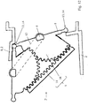
- Such an embodiment shows the major disadvantage of the presence of a disturbing element of the flow, and therefore necessarily generator of noises (whistles) and pressure drops, in the maximum open position of the aerator (cf. Figure 1B ).
- the median arrangement of the shutter requires sufficient clearance to allow the rotation of the shutter between its closed position and its maximum open position. This necessity is problematic when the space available is limited in the flow direction, which may be the case for aerators depending on their mounting location.
- the width of the orientation vanes are reduced or else cuts are made therein: these two measurements are detrimental for a good directivity of the flow.
- the rigid flap is retracted laterally by translation, by means of a rack and pinion system.
- the flexible flap is constituted by an assembly of slats (in the manner of a roller shutter) and driven in displacement by a meshing system to be retracted laterally.
- the general object of the present invention is to overcome at least the main disadvantages of the embodiments of the state of the art presented above.
- a closure shutter device for a gaseous fluid circulation duct comprising, on the one hand, a flap which is mounted in the duct and movable between a duct closed position of the passage of the duct and a maximum clearance position of said passage, preferably of substantially square or rectangular shape, on the other hand, at least one operating member controllable by a user and finally a motion transmission mechanism , cinematically connecting said member to said shutter, the latter being mounted in the duct with definition of a pivot axis for said flap.
- the flap is mounted in the duct with the ability to move in translation, in addition to its ability to pivot about the axis, between a median position in the passage of the duct and a staggered position. laterally.
- the transmission mechanism consists of a complex dual-link crank-crank system, comprising an effector in the form of a rotary knob, a rod forming a connecting rod and a crank-forming piece, integral with the axis of the flap and slidably guided between two plates on a part of the translation movement of the axis of the flap.
- the passage from the maximum open position (flap retracted laterally and parallel to the wall of the duct) to the total shutter position (flap positioned centrally with respect to the duct and oriented to block the passage of the duct) is obtained by two consecutive movements of the flap under the action of the rotary control knob, namely: first, a translation of the axis of the flap between a starting position laterally offset in the duct and an arrival position centered relative to to the duct (the axis being locked in rotation during this translational movement), then a rotation of the flap about its axis (which is then slidably locked in the extreme position of translation).
- this known embodiment has a number of drawbacks, in particular, on the one hand, a risk of blockage during the translational movement due to friction related to the tight guide of the crank and the significant inclination between the direction translation and the direction of application of the displacement force and, secondly, the need to provide a means of assisting the movement at the beginning of the displacement in translation, in the form of a spring means.
- the regulation of the flow through the duct is not proportional nor progressive over the entire control range (substantial absence of variation during the translational movement of the flap), and, given the different stresses during the two distinct phases and consecutive movement of the flap, comfort of use is degraded.
- the present invention aims more specifically to overcome the main limitations mentioned above, improving precisely in terms of reliability and ease of use, the known embodiment described above, and also advantageously decreasing the constructive complexity.
- the subject of the invention is such a shutter device, characterized in that the simultaneous movements of rotation and of translation are mutually subject to or rendered interdependent by means of a servo mechanism and the shutter is, in its maximum disengagement position, substantially pressed against one of the walls of said duct.
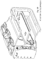
- FIGS 2 to 12 show, at least partially for some, a closure shutter device for gaseous fluid circulation duct, in particular shutter louver 1 for duct 2 of aerator 3.
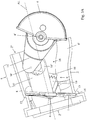
- This shutter device comprises, on the one hand, a shutter 1 which is mounted in the duct 2, and movable between a closed position of the passage 2 'of the duct 2 and a maximum disengagement position of said passage 2', preferably of substantially square or rectangular shape, on the other hand, at least one operating member 4 controllable by a user and finally a mechanism 5 of motion transmission (possibly with the latter), kinematically connecting said member 4 to said flap 1 .
- the shutter 1 is mounted in the duct 2 with a definition of a median pivot axis 6 for said shutter 1 and with the ability to move guided in translation, in addition to its ability to pivot about the axis 6, this between a position median in the passage 2 'of the duct 2 and a laterally offset position.
- the simultaneous movements of rotation and translation are mutually subject to or rendered interdependent by means of a servo mechanism 9 and the flap 1 is, in its maximum release position substantially pressed against one of the walls 8, 8 'of said duct 2.
- the constructive improvement of the invention makes it possible to release the passage 2 'from any obstacle, in particular at its central region, in the maximum open position.
- the pivot axis 6 is connected to two opposite walls 8 'of the duct 2 (advantageously of substantially square or rectangular section) so as to ensure a mounting with translational guiding and rotational ability of the flap 1 with respect to said duct 2, the actuating member 4 being configured to impart rotational movement to the flap 1 via the transmission mechanism 5, this rotational movement also being converted simultaneously in a translation movement through the servo mechanism 9, in cooperation with the mounting with translation guide of the axis 6.
- the servo-control mechanism 9 comprises at least one connection by meshing between a toothed element 10 secured to the shutter 1 or its pivot axis. 6 and a toothed element 11 integral with the conduit 2.
- the pivoting and mounting axis 6 is connected to the duct 2, on the one hand, by a sliding connection 7 adapted and intended to provide a guide in translation of said axis. 6 between a median position in the passage 2 'of the duct 2 and a position laterally offset towards a wall 8, 8' of said duct 2 and, on the other hand, by at least one link 9 by meshing, for example of the pinion type 10 - rack 11, fit and intended to rotate said axis 6 with simultaneous displacement of the latter in translation.
- These two links 7 and 9 are mutually configured and arranged to cooperate operationally with each other so as to impose on said shutter 1, under the action of the transmission mechanism 5 during the actuation of the operating member 4 a moving movement combining , simultaneously and interdependently, a controlled pivot about its axis 6 and a controlled displacement in translation of the latter, between extreme positions of closure and clearance of the passage 2 'of the duct 2.
- the rack mechanism 9 synchronizes with one another and mutually slaves, on the one hand, the rotational movement of the shutter 1 about its axis 6 and, on the other hand, the translational movement of said axis 6 in the guide rails or grooves 12 lateral of the slide connection 7 between the flap 1 and the duct 2.
- a median positioning of the pivot axis 6 necessarily corresponds to a rotational position of the shutter 1 along a plane substantially perpendicular to the flow direction D or the longitudinal axis AL of the duct 2 (total closed position of the passage 2 ').
- a laterally offset positioning (towards one of the walls 8, 8 'of the duct 2) of the pivot axis necessarily corresponds to a rotational position of the flap 1 offering a minimum resistance to flow, preferably with a positioning in a plane parallel to the flow direction D or the longitudinal axis AL of the duct 2 (maximum open position of the flap 1).
- the shutter 1 rotates with an amplitude close to 90 °, and at least 80 °, when the pivot axis 6 is displaced in translation between its two extreme positions (median and laterally offset).
- the axis of pivoting and mounting 6 may, for example, consist of a through body, for example metal, on which is molded the flap 1 and which protrudes, in the form of two portions of projecting axis, of part and other of the body of said flap 1.
- the axis of pivoting and mounting 6 may also consist solely of two axially aligned and protruding lateral portions of the body of the flap 1 with which they are formed.
- said axis 6 is advantageously laterally mounted with sliding ability in grooves or rectilinear parallel slots 12, which are formed in opposite walls 8 'of the duct 2, which extend substantially from the middle of said walls 8 'up to their upper or lower edges and which together define the slide connection 7.
- at least one mechanism 9 making the connection by meshing is associated with said shutter 1 or said axis 6, this mechanism 9 comprising a pinion or a portion of toothed wheel 10 integral with the shutter 1 or the axis 6 and a rack 11 integral with the conduit 2 or formed thereon.
- the sliding connection 7 [axis 6 / grooves 12] and the or each meshing connection 9 [rack 11 / gear portion 10] are configured and arranged mutually to cooperate operationally with each other so as to move the shutter 1 in a complex motion combining pivoting about its axis 6 and simultaneous displacement and proportional translation of said axis 6, this progressively between a closed position of the passage, wherein the flap 1 is positioned in a plane substantially perpendicular to the longitudinal axis AL of the duct 2 and with its axis 6 in the middle position, and a maximum opening position of said passage 2 ', in which the shutter 1 is offset against the upper wall 8 or lower of said duct 2 being advantageously positioned parallel to this wall 8, preferably substantially plated against it ( figure 12 ) or against an internal setback of the latter ( figure 11 ).
- FIG. 1 the orientations of the slideways 12 and the rack (s) 11 are mutually parallel or substantially parallel, the pinion or the toothed portion 10 of the or each connection 9 by meshing consists of a toothed angular sector of 90 ° formed on the flap 1 or the axis 6, and the release of the flap 1 is made in the direction of the upper wall 8 of the duct 2, the grooves or slots 12 of the slide links 7 and the or rack (s) 11 being inclined in the flow direction (D) of the gas stream flowing in the conduit 2, their lower ends to their upper ends.
- the shutter 1 is brought according to the invention as close as possible to the corresponding wall 8 of the duct 2, with preferentially a position parallel to the internal surface of the duct 2. this wall.
- said wall 8 has portions projecting towards the inside of the passage 2 'of the duct 2, these projecting parts define the maximum possible retraction, as illustrated for example by the figure 11 in relation to Figures 3B , 5A , 5B and 8 .
- the slides 12 as well as the components 10 and 11 of the link by meshing 9 are adapted in terms of size, shape and orientation to bring the axis 6 and thus the flap 1 into the correct extreme position ( cf. figure 12 ).
- the toothed angular sector 10 has a circular shape (cf. figure 11 ).
- the toothed sector 10 may have a non-circular and / or off-center outer circumference shape. relative to the axis 6 so as to ensure effective meshing at the link 9 over the entire extent of displacement of the axis 6 (cf. figure 12 ).
- the pipe 2 has internal shoulders or recesses 13 at its walls 8, 8 ', which form bearing surfaces for the flap 1 in position shutter, the latter being advantageously provided with a peripheral seal 14 bearing against these surfaces.
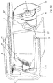
- the mechanism 5 for transmitting and transforming the movement comprises a first arm 15 rigidly secured to the operating member 4 in the form of a rotary knob, pivotally mounted relative to the duct 2, and a second arm 15 rigidly fixed to the shutter. 1 or the axis of pivoting and mounting 6 of said flap 1, these two arms 15 and 15 'being interconnected by an articulated connection 16 allowing a transmission of movement between the first arm 15 and the second arm 15', said movement being transformed by the sliding links 7 and meshing 9 connecting the flap 1 or its axis 6 to the duct 2 in a complex movement combining rotation and translation of said flap 1 and its axis 6.
- this articulated connection 16 between the first and second arms 15 and 15 ' is constituted by a lug or a finger 16' flowing in a groove or a groove 16 "and comprises a lug 16 'formed at the free end of the first arm 15 and a partial circular groove 16 "formed in the free end of the second arm 15 '.
- the mechanism 5 and the operating member 4 are arranged inside the outlet opening 2 "of the duct 2, the movement transmission mechanism 5 extending in said duct 2 and being kinematically connected to the shutter 1 , preferably to the part of the latter situated above its axis of pivoting and mounting 6.
- the two arms 15 and 15 'of the mechanism 5 and possibly a part of the member 4 are housed in the conduit 2, thus invisible from outside the aerator 3.
- a complementary part at least of the member 4, namely that intended to be manipulated by the user, must be accessible from the outside and therefore be prominent with respect to the outlet opening 2 "of the duct 2. This part is therefore located beyond the edge of the opening 2 ", and orientation fins 18 normally present and, where appropriate, a possible outer gate closing said opening 2".
- the pivot axis 4 'in the case of a rotary member 4 may be connected to the aforementioned fins 18, or be mounted on a crossbar or a specific bearing disposed in the opening 2 ".
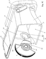
- the operating member 4 and the motion transmission mechanism 5 are arranged on an outer lateral side of the duct 2, said mechanism 5 being connected to a portion of the pivoting and mounting axis 6 of the shutter 1 which is mounted through a slide 12 formed in an adjacent side wall 8 'of the duct 2.
- the member 4 is offset relative to the outlet opening 2 "and therefore situated outside the outgoing air flow, Furthermore, this configuration makes it possible to use the duct 2 and the surrounding environment. of the latter as a mounting bracket for the mechanism 5 and the member 4.
- the second arm 15 'of the motion transmission mechanism 5 comprises a flange 17 configured to close the through slide 12 formed in the wall 8' of the duct 2, which regardless of the position of strand 1.
- this flange 17 advantageously has a shape of 8 or butterfly wings and is integral with the axis 6, and located in support of the outside of the slot or through groove 12 forming a slide, each part of the 8 or wing having a adapted shape and an extension sufficient to cover the entire surface of said slot 12.
- the second arm 15 'of the mechanism 5 can be formed in one piece with the flap 1 ( figures 4 and 5 ) or be rigidly assembled with the shutter 1 by an interlocking connection with locking by elastic engagement and / or notches ( figure 10 ).
- the first arm 15 of the mechanism 5 can itself be formed in one piece with the body of the rotary knob 4 forming the actuating member, in the form of a lateral extension of the latter (see in particular figures 5 and 6 ).
- the rotary knob 4 may have stop means 19, such as for example nipples, lugs, shoulders or the like coming into contact during the rotation of said knob 4 with counter-stop means 19 ', arranged on the conduit 2 for example.
- the present invention also relates, as illustrated in part to the Figures 2A and 2B , a motor vehicle ventilator essentially comprising a duct 2, a shutter 1 mounted in the duct 2 and controllable by means of an operating member 4 and a plurality of fins 18 for diffusing and orienting the air flow exiting the aerator 3, mounted at the outlet opening 2 "of the duct 2 of the latter.
- This aerator 3 is characterized in that the shutter 1 and the operating member 4 are part of a shutter device as described above, the shutter 1 and the section of the passage 2 'of the duct 2 receiving the latter having a shape generally substantially square or rectangular.
- the flap 1 allows, in its retracted position laterally, to conceal any areas of disturbance of the flow in the passage 2 ', related to recesses, narrowing or other internal inequalities from constructive necessities 2. In its intermediate positions, the flap 1 further participates in a directional guidance of said flow.
- the invention also relates to a motor vehicle characterized in that it comprises at least one aerator 3 as described above.
Abstract
La présente invention a pour objet un dispositif de volet d'obturation pour conduit d'aérateur comprenant, d'une part, un volet (1) mobile entre une position d'obturation du passage du conduit (2) et une position de dégagement maximal dudit passage, d'autre part, au moins un organe de manoeuvre et, enfin, un mécanisme (5) de transmission, reliant cinématiquement ledit organe audit volet (1), ce dernier étant monté dans le conduit (2) avec définition d'un axe de pivotement médian pour ledit volet (1). Dispositif caractérisé en ce que le volet (1) est monté dans le conduit (2) avec faculté de déplacement guidé en translation, en plus de sa faculté de pivotement autour de l'axe, ce entre une position médiane dans le passage du conduit (2) et une position décalée latéralement, les mouvements de rotation et de translation étant rendus interdépendants par l'intermédiaire d'un mécanisme d'asservissement et le volet (1) étant, dans sa position de dégagement maximal, sensiblement plaqué contre l'une des parois (8, 8') dudit conduit (2).The present invention relates to a closure shutter device for aerator conduit comprising, on the one hand, a flap (1) movable between a closed position of the duct passage (2) and a maximum clearance position said passage, on the other hand, at least one operating member and, finally, a transmission mechanism (5) kinematically connecting said member to said shutter (1), the latter being mounted in the duct (2) with definition of a median pivot axis for said flap (1). Device characterized in that the flap (1) is mounted in the duct (2) with translational movement, in addition to its ability to pivot about the axis, between a median position in the passage of the duct ( 2) and a laterally offset position, the rotational and translational movements being rendered interdependent by means of a servo mechanism and the flap (1) being, in its maximum disengagement position, substantially pressed against one walls (8, 8 ') of said duct (2).
Description
La présente invention concerne le domaine des équipements intérieurs de véhicules automobiles, plus particulièrement les moyens de réglage des flux d'air injectés dans l'habitacle, et a pour objet un dispositif de volet d'obtention pour conduit de circulation de fluide gazeux et un aérateur comportant un tel dispositif.The present invention relates to the field of interior equipment of motor vehicles, more particularly the means for adjusting the air flows injected into the passenger compartment, and relates to a device for obtaining shutter for a gaseous fluid circulation duct and a aerator comprising such a device.
De nombreuses constructions d'aérateurs ou bouches d'aération commandables sont connues dans l'état de la technique.Many constructions aerators or controllable air vents are known in the state of the art.
Un tel aérateur est généralement intégré dans une pièce de garniture intérieure d'un véhicule (tableau de bord, intérieur de portière, siège, ...) et comprend une portion de conduit, un ou plusieurs types d'ailettes, un organe de régulation du flux et un organe de commande pour régler le débit et/ou l'orientation du flux d'air expulsé par l'aérateur.Such an aerator is generally integrated in a vehicle interior trim part (dashboard, inside door, seat, ...) and comprises a portion of duct, one or more types of fins, a regulating member flow and a control member for adjusting the flow rate and / or the direction of the flow of air expelled by the aerator.
Généralement, des ailettes d'orientation du flux sont disposées au niveau de l'ouverture de sortie et au moins un volet d'obturation du passage du conduit est situé à l'arrière de ces ailettes, dans le conduit de l'aérateur.Generally, flow orientation vanes are disposed at the outlet opening and at least one shutter of the duct passage is located at the rear of these fins, in the duct of the aerator.
Pour des raisons de simplicité constructive et de facilité de commande, la mise en oeuvre d'un unique volet d'obturation est préférée.For reasons of constructive simplicity and ease of control, the implementation of a single shutter shutter is preferred.
Une construction classique consiste à prévoir un volet obturateur rotatif monté sur un axe de pivotement arrangé de manière centrée ou médiane dans le passage du conduit. Ce volet peut être entrainé de différentes manières : par biellette (
Une telle réalisation fait état de l'inconvénient majeur de la présence d'un élément perturbateur du flux, et donc obligatoirement générateur de bruits (sifflements) et de pertes de charge, en position d'ouverture maximale de l'aérateur (cf.
De plus, l'arrangement médian du volet nécessite de prévoir un dégagement suffisant pour permettre la rotation du volet entre sa position de fermeture et sa position d'ouverture maximale. Cette nécessité pose problème lorsque l'encombrement disponible est limité dans la direction du flux, ce qui peut être le cas pour des aérateurs en fonction de leur emplacement de montage.In addition, the median arrangement of the shutter requires sufficient clearance to allow the rotation of the shutter between its closed position and its maximum open position. This necessity is problematic when the space available is limited in the flow direction, which may be the case for aerators depending on their mounting location.
Pour surmonter ce problème, la largeur des ailettes d'orientation sont réduites ou alors des découpes y sont réalisées : ces deux mesures sont nuisibles pour une bonne directivité du flux.To overcome this problem, the width of the orientation vanes are reduced or else cuts are made therein: these two measurements are detrimental for a good directivity of the flow.
On a déjà proposé dans l'état de la technique, pour surmonter les limitations précitées, d'autres constructions de volets d'obturation.It has already been proposed in the state of the art, to overcome the above limitations, other shutter shutter constructions.
Ainsi, dans les documents
Dans le document
Toutefois, ces constructions sont complexes et encombrantes, nécessite un dégagement latéral important et sont inadaptées pour un montage dans un conduit d'aérateur.However, these constructions are complex and cumbersome, require significant lateral clearance and are unsuitable for mounting in an aerator duct.
Par ailleurs, il a également été proposé, par exemple dans le document
Néanmoins, dans cette dernière construction, il faut à nouveau disposer d'un espace dégagé suffisant dans la direction longitudinale du conduit recevant ce volet.Nevertheless, in this latter construction, it is again necessary to have sufficient clear space in the longitudinal direction of the duct receiving this flap.
En outre, sa manoeuvre nécessite un couple élevé compte tenu de la position en extrémité de l'axe, en particulier pour contrer les forces de poussées générées par le flux d'air circulant sur le volet.In addition, its operation requires a high torque given the position at the end of the axis, in particular to counter the thrust forces generated by the flow of air flowing on the flap.
Le but général de la présente invention consiste à surmonter au moins les principaux inconvénients des réalisations de l'état de la technique présentées ci-dessus.The general object of the present invention is to overcome at least the main disadvantages of the embodiments of the state of the art presented above.
Par le document
En outre, dans ce dispositif connu, le volet est monté dans le conduit avec faculté de déplacement guidé en translation, en plus de sa faculté de pivotement autour de l'axe, ce entre une position médiane dans le passage du conduit et une position décalée latéralement.In addition, in this known device, the flap is mounted in the duct with the ability to move in translation, in addition to its ability to pivot about the axis, between a median position in the passage of the duct and a staggered position. laterally.
Dans ledit document
Le passage de la position d'ouverture maximale (volet escamoté latéralement et parallèle à la paroi du conduit) à la position d'obturation totale (volet positionné de manière centrée par rapport au conduit et orienté pour bloquer le passage du conduit) est obtenu par deux mouvements consécutifs du volet sous l'action du bouton rotatif de commande, à savoir : tout d'abord, une translation de l'axe du volet entre une position de départ décalée latéralement dans le conduit et une position d'arrivée centrée par rapport au conduit (l'axe étant bloqué en rotation durant ce mouvement de translation), puis une rotation du volet autour de son axe (lequel est alors bloqué en coulissement en position extrême de translation).The passage from the maximum open position (flap retracted laterally and parallel to the wall of the duct) to the total shutter position (flap positioned centrally with respect to the duct and oriented to block the passage of the duct) is obtained by two consecutive movements of the flap under the action of the rotary control knob, namely: first, a translation of the axis of the flap between a starting position laterally offset in the duct and an arrival position centered relative to to the duct (the axis being locked in rotation during this translational movement), then a rotation of the flap about its axis (which is then slidably locked in the extreme position of translation).
L'enchaînement de mouvements est inversé pour le passage de l'obturation totale à l'ouverture maximale.The sequence of movements is reversed for the transition from the total shutter to the maximum aperture.
Toutefois, cette réalisation connue présente un certain nombre d'inconvénients, en particulier, d'une part, un risque de blocage durant le mouvement de translation du fait des frictions liées au guidage serré de la manivelle et de l'inclinaison importante entre la direction de translation et la direction d' application de la force de déplacement et, d'autre part, la nécessité de devoir prévoir un moyen d'aide au mouvement au début du déplacement en translation, sous forme d'un moyen ressort.However, this known embodiment has a number of drawbacks, in particular, on the one hand, a risk of blockage during the translational movement due to friction related to the tight guide of the crank and the significant inclination between the direction translation and the direction of application of the displacement force and, secondly, the need to provide a means of assisting the movement at the beginning of the displacement in translation, in the form of a spring means.
De plus, la régulation du flux à travers le conduit n'est pas proportionnelle, ni progressive sur toute la plage de commande (absence substantielle de variation durant le mouvement de translation du volet), et, compte-tenu des sollicitations différentes durant les deux phases distinctes et consécutives du déplacement du volet, le confort d'utilisation est dégradé.In addition, the regulation of the flow through the duct is not proportional nor progressive over the entire control range (substantial absence of variation during the translational movement of the flap), and, given the different stresses during the two distinct phases and consecutive movement of the flap, comfort of use is degraded.
Enfin, dans sa position décalée, le volet constitue encore un obstacle non négligeable à l'écoulement, perturbant le flux dans le conduit.Finally, in its offset position, the flap is still a significant obstacle to flow, disrupting the flow in the conduit.
La présente invention a pour but plus spécifique de pallier les principales limitations précitées, en améliorant, justement en termes de fiabilité et de confort d'utilisation, la réalisation connue décrite ci-dessus, et en diminuant avantageusement également la complexité constructive.The present invention aims more specifically to overcome the main limitations mentioned above, improving precisely in terms of reliability and ease of use, the known embodiment described above, and also advantageously decreasing the constructive complexity.
A cet effet, l'invention a pour objet un tel dispositif de volet caractérisé en ce que les mouvements simultanés de rotation et de translation sont mutuellement assujettis ou rendus interdépendants par l'intermédiaire d'un mécanisme d'asservissement et le volet est, dans sa position de dégagement maximal, sensiblement plaqué contre l'une des parois dudit conduit.For this purpose, the subject of the invention is such a shutter device, characterized in that the simultaneous movements of rotation and of translation are mutually subject to or rendered interdependent by means of a servo mechanism and the shutter is, in its maximum disengagement position, substantially pressed against one of the walls of said duct.
L'invention sera mieux comprise, grâce à la description ci-après, qui se rapporte à des modes de réalisation préférés, donnés à titre d'exemples non limitatifs, et expliqués avec référence aux dessins schématiques annexés, dans lesquels :
- les
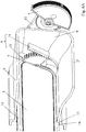
figures 1A et1B sont des vues partielles en coupe et en élévation latérale d'un dispositif de volet d'obturation pivotant selon l'état de la technique, respectivement en position de fermeture totale (figure 1A ) et en position d'ouverture maximale (figure 1B ) ; - la
figure 2 est une vue similaire à lafigure 1A , illustrant un dispositif de volet d'obturation selon un premier mode de réalisation de l'invention en position de fermeture totale ; - les
figures 3A et3B sont des vues en coupe et en élévation du dispositif représentéfigure 2 , en position de fermeture totale (figure 3A ) et en position d'ouverture maximale (figure 3B ) ; - la
figure 4 est une vue en perspective selon une autre direction de l'objet représentéfigures 2A et3A ; - les
figures 5A ,5B , et5C sont des vues en perspective selon trois directions différentes de l'objet représentéfigure 3B ; - les
figures 6A et6B sont des vues partielles en coupe et en perspective d'un dispositif de volet selon un second mode de réalisation de l'invention, le volet étant en position de fermeture totale ; - la
figure 7 est une vue partiellement par transparence et en perspective selon une autre direction de l'objet représentéfigures 6A et6B ; - la
figure 8 est une vue similaire à celle de lafigure 7 , le volet étant en position d'ouverture maximale ; - les
figures 9A et9B sont des vues en perspective selon deux directions différentes de l'ensemble structurel et fonctionnel [volet / mécanisme d'asservissement / mécanisme de transmission / bouton de manoeuvre] faisant partie du dispositif de volet représentéfigures 6 à 8 ; - la
figure 10 est une vue éclatée du volet et de son bras d'actionnement faisant partie de l'ensemble représentéfigures 9A et9B , selon une variante de réalisation de l'invention ; - la
figure 11 est une vue schématique simplifiée en élévation latérale selon la direction de l'axe de pivotement et de montage du volet du dispositif représentéfigures 2 à 10 , illustrant simultanément les deux positions opposées extrémales (fermeture totale et ouverture maximale) du volet d'obturation, et, - la
figure 12 est une représentation similaire à celle de lafigure 11 d'une variante de réalisation de l'invention, dans laquelle le volet peut être déplacé dans une position d'ouverture maximale correspondant à un escamotage total contre la paroi du conduit.
- the
Figures 1A and1B are partial views in section and in side elevation of a pivoting shutter device according to the state of the art, respectively in the fully closed position (Figure 1A ) and in the maximum open position (Figure 1B ); - the
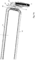
figure 2 is a view similar to theFigure 1A , illustrating a closure shutter device according to a first embodiment of the invention in the fully closed position; - the
Figures 3A and3B are sectional and elevational views of the device shownfigure 2 , in the fully closed position (figure 3A ) and in the maximum open position (figure 3B ); - the
figure 4 is a perspective view in another direction of the object shownFigures 2A and3A ; - the
Figures 5A ,5B , and5C are perspective views in three different directions of the object representedfigure 3B ; - the
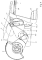
Figures 6A and6B are partial views in section and in perspective of a shutter device according to a second embodiment of the invention, the shutter being in the fully closed position; - the
figure 7 is a view partially in transparency and in perspective according to another direction of the object representedFigures 6A and6B ; - the
figure 8 is a view similar to that of thefigure 7 the shutter being in the maximum open position; - the
Figures 9A and9B are perspective views in two different directions of the structural and functional assembly [shutter / servo mechanism / transmission mechanism / operating knob] forming part of the shutter device shownFigures 6 to 8 ; - the
figure 10 is an exploded view of the shutter and its actuating arm forming part of the assembly shownFigures 9A and9B according to an alternative embodiment of the invention; - the
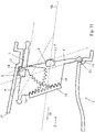
figure 11 is a simplified schematic view in side elevation along the direction of the axis of pivoting and mounting of the shutter of the device shownFigures 2 to 10 , simultaneously illustrating the two opposite extreme positions (total closure and maximum opening) of the shutter, and, - the
figure 12 is a representation similar to that of thefigure 11 of an alternative embodiment of the invention, wherein the flap can be moved to a maximum open position corresponding to a total retraction against the duct wall.
Les
Ce dispositif de volet comprend, d'une part, un volet 1 qui est monté dans le conduit 2, et mobile entre une position d'obturation du passage 2' du conduit 2 et une position de dégagement maximal dudit passage 2', préférentiellement de forme sensiblement carrée ou rectangulaire, d'autre part, au moins un organe de manoeuvre 4 commandable par un utilisateur et, enfin, un mécanisme 5 de transmission de mouvement (éventuellement avec transformation de ce dernier), reliant cinématiquement ledit organe 4 audit volet 1.This shutter device comprises, on the one hand, a
Le volet 1 est monté dans le conduit 2 avec définition d'un axe de pivotement 6 médian pour ledit volet 1 et avec faculté de déplacement guidé en translation, en plus de sa faculté de pivotement autour de l'axe 6, ce entre une position médiane dans le passage 2' du conduit 2 et une position décalée latéralement.The
Conformément à l'invention, les mouvements simultanés de rotation et de translation sont mutuellement assujettis ou rendus interdépendants par l'intermédiaire d'un mécanisme d'asservissement 9 et le volet 1 est, dans sa position de dégagement maximal sensiblement plaqué contre l'une des parois 8, 8' dudit conduit 2.According to the invention, the simultaneous movements of rotation and translation are mutually subject to or rendered interdependent by means of a
Ainsi, sans complexifier notablement la structure du dispositif connu des
En outre, en combinant au niveau du volet 1 les mouvements de rotation et de translation en un déplacement complexe liant entre elles de manière concomitante et interdépendante ces deux composantes cinématiques, ce sur toute la plage de commande fournie par l'organe 4, on aboutit à une manoeuvre plus fluide pour l'utilisateur et, surtout, avec un résultat progressif par rapport à l'actionnement effectué par ce dernier.Furthermore, by combining at
Selon une caractéristique constructive de l'invention, et en relation avec un organe 4 rotatif, l'axe de pivotement 6 est relié à deux parois opposées 8' du conduit 2 (avantageusement de section sensiblement carrée ou rectangulaire) de manière à assurer un montage avec guidage en translation et faculté de rotation du volet 1 par rapport audit conduit 2, l'organe de manoeuvre 4 étant configuré pour impartir un mouvement de rotation au volet 1 par le biais du mécanisme 5 de transmission, ce mouvement de rotation étant également converti simultanément en un mouvement de translation par l'intermédiaire du mécanisme d'asservissement 9, en coopération avec le montage avec guidage en translation de l'axe 6.According to a constructive feature of the invention, and in relation to a
Afin de pouvoir fournir une relation précise et sans jeu entre les deux types de mouvements, il est avantageusement prévu que le mécanisme d'asservissement 9 comprenne au moins une liaison par engrènement entre un élément denté 10 solidaire du volet 1 ou de son axe de pivotement 6 et un élément denté 11 solidaire du conduit 2.In order to be able to provide a precise and play-free relationship between the two types of movements, it is advantageously provided that the servo-
Plus précisément, et en accord avec une variante de réalisation pratique avantageuse, l'axe de pivotement et de montage 6 est relié au conduit 2, d'une part, par une liaison glissière 7 apte et destinée à réaliser un guidage en translation dudit axe 6 entre une position médiane dans le passage 2' du conduit 2 et une position décalée latéralement vers une paroi 8, 8' dudit conduit 2 et, d'autre part, par au moins une liaison 9 par engrènement, par exemple du type pignon 10 - crémaillère 11, apte et destinée à réaliser une rotation dudit axe 6 avec déplacement simultané de ce dernier en translation. Ces deux liaisons 7 et 9 sont configurées et arrangées mutuellement pour coopérer opérationnellement entre elles de manière à imposer audit volet 1, sous l'action du mécanisme de transmission 5 lors de l'actionnement de l'organe de manoeuvre 4 un mouvement de déplacement combinant, de manière simultanée et interdépendante, un pivotement contrôlé autour de son axe 6 et un déplacement contrôlé en translation de ce dernier, ce entre des positions extrêmes d'obturation et de dégagement du passage 2' du conduit 2.More specifically, and in accordance with an advantageous practical embodiment variant, the pivoting and
Comme cela ressort des dessins annexés, le mécanisme à crémaillère 9 synchronise entre eux et asservit mutuellement, d'une part, le mouvement de rotation du volet 1 autour de son axe 6 et, d'autre part, le mouvement de translation dudit axe 6 dans les glissières ou rainures de guidage 12 latérales de la liaison glissière 7 entre le volet 1 et le conduit 2.As can be seen from the appended drawings, the
L'asservissement des deux mouvements est avantageusement paramétré constructivement de telle manière qu'un positionnement médian de l'axe de pivotement 6 corresponde obligatoirement à une position en rotation du volet 1 selon sur un plan sensiblement perpendiculaire à la direction d'écoulement D ou à l'axe longitudinal AL du conduit 2 (position de fermeture totale du passage 2'). D'autre part, un positionnement décalé latéralement (vers une des parois 8, 8' du conduit 2) de l'axe de pivotement correspond obligatoirement à une position en rotation du volet 1 offrant une résistance minimale à l'écoulement, préférentiellement avec un positionnement selon un plan parallèle à la direction d'écoulement D ou à l'axe longitudinal AL du conduit 2 (position d'ouverture maximale du volet 1).The enslavement of the two movements is advantageously parametered constructively so that a median positioning of the
Préférentiellement, et comme le montrent les
L'axe de pivotement et de montage 6 peut, par exemple, consister en un corps traversant, par exemple métallique, sur lequel est surmoulé le volet 1 et qui dépasse, sous la forme de deux portions d'axe saillantes, de part et d'autre du corps dudit volet 1.The axis of pivoting and mounting 6 may, for example, consist of a through body, for example metal, on which is molded the
L'axe de pivotement et de montage 6 peut également consister uniquement en deux portions d'axe alignées et proéminentes latéralement du corps du volet 1 avec lequel elles sont formées.The axis of pivoting and mounting 6 may also consist solely of two axially aligned and protruding lateral portions of the body of the
Quel que soit son mode de réalisation, ledit axe 6 est avantageusement monté latéralement avec faculté de glissement dans des rainures ou fentes rectilignes 12 parallèles, qui sont ménagées dans des parois opposées 8' du conduit 2, qui s'étendent sensiblement du milieu desdites parois 8' jusqu'à leurs bords supérieurs ou inférieurs et qui définissent ensemble la liaison glissière 7. De plus, au moins un mécanisme 9 réalisant la liaison par engrènement est associé audit volet 1 ou audit axe 6, ce mécanisme 9 comprenant un pignon ou une portion de roue dentée 10 solidaire du volet 1 ou de l'axe 6 et une crémaillère 11 solidaire du conduit 2 ou formée sur ce dernier. La liaison glissière 7 [axe 6 / rainures 12] et la ou chaque liaison par engrènement 9 [crémaillère 11 / portion de roue dentée 10] sont configurées et arrangées mutuellement pour coopérer opérationnellement entre elles de manière à déplacer le volet 1 selon un mouvement complexe combinant pivotement autour de son axe 6 et déplacement simultané et proportionnel en translation dudit axe 6, ce progressivement entre une position d'obturation du passage, dans laquelle le volet 1 est positionné selon un plan sensiblement perpendiculaire à l'axe longitudinal AL du conduit 2 et avec son axe 6 en position médiane, et une position d'ouverture maximale dudit passage 2', dans laquelle le volet 1 est déporté contre la paroi supérieure 8 ou inférieure dudit conduit 2 en étant avantageusement positionné parallèlement à cette paroi 8, préférentiellement sensiblement plaqué contre cette dernière (
En accord avec une construction pratique préférée du dispositif selon l'invention, ressortant notamment des
En position d'ouverture maximale, le volet 1 est amené selon l'invention au plus près de la paroi 8 correspondante du conduit 2, avec préférentiellement un positionnement parallèle à la surface intérieure de cette paroi. Lorsque ladite paroi 8 comporte des parties saillantes vers l'intérieur du passage 2' du conduit 2, ces parties saillantes définissent l'escamotage maximal possible, comme l'illustrent par exemple la
Il peut également être envisagé, en relation avec une variante de réalisation de l'invention illustrée schématiquement sur la
A cet effet, les glissières 12 ainsi que les composantes 10 et 11 de la liaison par engrènement 9 sont adaptées en termes de taille, de forme et d'orientation pour amener l'axe 6 et donc le volet 1 dans la position extrêmale adéquate (cf.
L'homme du métier comprend que lorsque le guidage en translation de l'axe de pivotement 6 s'effectue parallèlement à la barre rectiligne dentée formant la crémaillère 11 (glissières 12 situées dans un plan parallèle à cette dernière), le secteur angulaire denté 10 présente une forme circulaire (cf.
Toutefois, lorsque la position escamotée finale à atteindre pour l'axe de pivotement 6 impose une trajectoire en translation qui n'est pas parallèle à la crémaillère 11, le secteur denté 10 peut présenter une forme de pourtour extérieur non circulaire et/ou décentrée par rapport à l'axe 6 de manière à assurer un engrènement effectif au niveau de la liaison 9 sur toute l'étendue de déplacement de l'axe 6 (cf.
En particulier lorsque la liaison d'engrènement 9 est déportée de manière importante latéralement par rapport au plan médian ou au centre du volet 1 et du passage 2' du conduit 2 comme par exemple dans les modes de réalisation illustrés et que ledit volet 1 et ledit passage 2' présente une largeur importante, il peut être avantageusement prévu de dédoubler cette liaison d'engrènement 9, en prévoyant une seconde liaison de ce type (non représentée) du côté opposé du conduit 2, pour assurer une meilleure stabilité et un meilleur guidage du volet 1.In particular, when the
En vue de pouvoir garantir une position de fermeture totale reproductible et stable, avec réalisation d'une bonne étanchéité, le conduit 2 comporte des épaulements ou décrochements internes 13 au niveau de ses parois 8, 8', qui forment surfaces d'appui pour le volet 1 en position d'obturation, ce dernier étant avantageusement pourvu d'un joint périphérique 14 venant en appui contre ces surfaces.In order to be able to guarantee a total reproducible and stable closed position, with the achievement of a good seal, the
Avantageusement, le mécanisme 5 de transmission et de transformation du mouvement comprend un premier bras 15 solidaire rigidement de l'organe de manoeuvre 4 sous forme de bouton rotatif, monté pivotant par rapport au conduit 2, et un second bras 15' solidaire rigidement du volet 1 ou de l'axe de pivotement et de montage 6 dudit volet 1, ces deux bras 15 et 15' étant reliés entre eux par une liaison articulée 16 autorisant une transmission de mouvement entre le premier bras 15 et le second bras 15', ledit mouvement étant transformé par les liaisons à glissière 7 et à engrènement 9 reliant le volet 1 ou son axe 6 au conduit 2 en un déplacement complexe combinant rotation et translation dudit volet 1 et de son axe 6.Advantageously, the
Ainsi, une seule liaison articulée est mise en oeuvre pour transmettre le mouvement de l'organe de manoeuvre 4 au volet 1.Thus, a single articulated connection is implemented to transmit the movement of the operating
Préférentiellement, cette liaison articulée 16 entre les premier et second bras 15 et 15' est constituée par un ergot ou un doigt 16' circulant dans une rainure ou une gorge 16" et comprend un ergot 16' formé au niveau de l'extrémité libre du premier bras 15 et une rainure circulaire partielle 16" ménagée dans l'extrémité libre du second bras 15'.Preferably, this articulated
Conformément à un premier mode de réalisation de l'invention, illustré aux
Ainsi, les deux bras 15 et 15' du mécanisme 5 et éventuellement une partie de l'organe 4 sont logés dans le conduit 2, donc invisibles de l'extérieur de l'aérateur 3.Thus, the two
Une partie complémentaire au moins de l'organe 4, à savoir celle destinée à être manipulée par l'utilisateur, doit être accessible de l'extérieur et donc être proéminente par rapport à l'ouverture de sortie 2" du conduit 2. Cette partie est par conséquent située au-delà du bord de l'ouverture 2", et des ailettes d'orientation 18 normalement présentes et, le cas échéant, d'une éventuelle grille extérieure fermant ladite ouverture 2".A complementary part at least of the
L'axe de pivotement 4' dans le cas d'un organe 4 rotatif peut être relié aux ailettes 18 précitées, ou être monté sur une traverse ou un palier spécifique disposé(e) dans l'ouverture 2".The pivot axis 4 'in the case of a
Conformément à un second mode de réalisation de l'invention, illustré sur les
Dans cette seconde construction, l'organe 4 est déporté par rapport à l'ouverture de sortie 2" et donc situé en dehors du flux d'air sortant. En outre, cette configuration permet d'utiliser le conduit 2 et l'environnement alentour de ce dernier comme support de montage pour le mécanisme 5 et l'organe 4.In this second construction, the
Afin de limiter les fuites d'air parasites, il peut être avantageusement prévu que le second bras 15' du mécanisme 5 de transmission de mouvement comporte un flasque 17 configuré pour obturer la glissière traversante 12 ménagée dans la paroi 8' du conduit 2, ce quelle que soit la position du volet 1.In order to limit the parasitic air leaks, it can be advantageously provided that the second arm 15 'of the
Comme le montrent les
Le second bras 15' du mécanisme 5 peut être formé d'un seul tenant avec le volet 1 (
Le premier bras 15 du mécanisme 5 peut quant à lui être formé d'un seul tenant avec le corps du bouton rotatif 4 formant l'organe de manoeuvre, sous la forme d'une extension latérale de ce dernier (voir notamment
Par ailleurs, le bouton rotatif 4 peut présenter des moyens de butée 19, tels que par exemple des mamelons, des ergots, des épaulements ou analogues venant en contact lors de la rotation dudit bouton 4 avec des moyens de contre-butée 19', arrangés sur le conduit 2 par exemple.Furthermore, the
Ces moyens 19 et 19' coopérants définissent ainsi l'amplitude de pivotement dudit bouton 4 qui correspond à un déplacement du volet 1 entre sa position de fermeture et sa position d'ouverture.These cooperating means 19 and 19 'thus define the pivoting amplitude of said
La présente invention concerne également, comme illustré en partie sur les
Cet aérateur 3 est caractérisé en ce que le volet 1 et l'organe de manoeuvre 4 font partie d'un dispositif de volet tel que décrit précédemment, le volet 1 et la section du passage 2' du conduit 2 recevant ce dernier présentant une forme générale sensiblement carrée ou rectangulaire.This
Comme cela ressort partiellement des
Enfin, l'invention porte également sur véhicule automobile caractérisé en ce qu'il comprend au moins un aérateur 3 tel que décrit précédemment.Finally, the invention also relates to a motor vehicle characterized in that it comprises at least one
Bien entendu, l'invention n'est pas limitée aux modes de réalisation décrits et représentés aux dessins annexés. Des modifications restent possibles, notamment du point de vue de la constitution des divers éléments ou par substitution d'équivalents techniques, sans sortir pour autant du domaine de protection de l'invention.Of course, the invention is not limited to the embodiments described and shown in the accompanying drawings. Modifications are possible, particularly from the point of view of the constitution of the various elements or by substitution of technical equivalents, without departing from the scope of protection of the invention.
Claims (14)
ce dispositif de volet comprenant, d'une part, un volet (1) qui est monté dans le conduit (2), et mobile entre une position d'obturation du passage (2') du conduit (2) et une position de dégagement maximal dudit passage (2'), préférentiellement de forme sensiblement carrée ou rectangulaire, d'autre part, au moins un organe de manoeuvre (4) commandable par un utilisateur et, enfin, un mécanisme (5) de transmission, éventuellement avec transformation, de mouvement, reliant cinématiquement ledit organe (4) audit volet (1), ce dernier étant monté dans le conduit (2) avec définition d'un axe de pivotement (6) médian pour ledit volet (1),
dispositif de volet dans lequel le volet (1) est monté dans le conduit (2) avec faculté de déplacement guidé en translation, en plus de sa faculté de pivotement autour de l'axe (6), ce entre une position médiane dans le passage (2') du conduit (2) et une position décalée latéralement,
dispositif de volet caractérisé en ce que les mouvements simultanés de rotation et de translation sont mutuellement assujettis ou rendus interdépendants par l'intermédiaire d'un mécanisme d'asservissement (9) et le volet (1) est, dans sa position de dégagement maximal, sensiblement plaqué contre l'une des parois (8, 8') dudit conduit (2).Shutter shutter device for a gaseous fluid circulation duct, in particular a shutter shutter for an aerator duct,
this shutter device comprising, on the one hand, a flap (1) which is mounted in the duct (2), and movable between a closed position of the passage (2 ') of the duct (2) and a disengagement position maximum of said passage (2 '), preferably of substantially square or rectangular shape, on the other hand, at least one operating member (4) controllable by a user and finally a transmission mechanism (5), possibly with transformation, movement, kinematically connecting said member (4) to said flap (1), the latter being mounted in the duct (2) with definition of a pivot axis (6) median for said flap (1),
shutter device in which the shutter (1) is mounted in the duct (2) with translational movement, in addition to its ability to pivot about the axis (6), between a central position in the passage (2 ') of the duct (2) and a laterally offset position,
shutter device characterized in that the simultaneous movements of rotation and translation are mutually secured or rendered interdependent by means of a servo mechanism (9) and the flap (1) is, in its maximum disengagement position, substantially pressed against one of the walls (8, 8 ') of said duct (2).
aérateur (3) caractérisé en ce que le volet (1) et l'organe de manoeuvre (4) font partie d'un dispositif selon l'une quelconque des revendications 1 à 12, le volet (1) et la section du passage (2') du conduit (2) recevant ce dernier présentant une forme générale sensiblement carrée ou rectangulaire.Motor vehicle ventilator essentially comprising a duct (2), a shutter (1) mounted in the duct (2) and controllable by means of an operating member (4) and a plurality of fins (18). ) of diffusion and orientation of the air flow leaving the aerator (3), mounted at the outlet opening (2 ") of the duct (2) thereof,
aerator (3) characterized in that the flap (1) and the actuating member (4) are part of a device according to any one of claims 1 to 12, the flap (1) and the section of the passage ( 2 ') of the duct (2) receiving the latter having a substantially square or rectangular general shape.
Applications Claiming Priority (1)
| Application Number | Priority Date | Filing Date | Title |
|---|---|---|---|
| FR1658984A FR3056458B1 (en) | 2016-09-23 | 2016-09-23 | SHUTTER COMPONENT DEVICE FOR AERATION PIPE |
Publications (2)
| Publication Number | Publication Date |
|---|---|
| EP3299198A1 true EP3299198A1 (en) | 2018-03-28 |
| EP3299198B1 EP3299198B1 (en) | 2019-06-26 |
Family
ID=57960528
Family Applications (1)
| Application Number | Title | Priority Date | Filing Date |
|---|---|---|---|
| EP17306153.2A Not-in-force EP3299198B1 (en) | 2016-09-23 | 2017-09-06 | Shutter device for closing a ventilation duct |
Country Status (3)
| Country | Link |
|---|---|
| EP (1) | EP3299198B1 (en) |
| BR (1) | BR102017020189A2 (en) |
| FR (1) | FR3056458B1 (en) |
Cited By (1)
| Publication number | Priority date | Publication date | Assignee | Title |
|---|---|---|---|---|
| WO2020200922A1 (en) * | 2019-04-04 | 2020-10-08 | Schneider Kunststoffwerke Gmbh | Coupling arrangement between an air-guiding element and a drive device, and air vent having a lamella arrangement |
Citations (11)
| Publication number | Priority date | Publication date | Assignee | Title |
|---|---|---|---|---|
| US3602127A (en) | 1969-03-21 | 1971-08-31 | Rootes Morors Ltd | Air vents |
| JPS60161216A (en) * | 1984-02-01 | 1985-08-22 | Nippon Denso Co Ltd | Blow-off air controller |
| JP2002179784A (en) | 2001-12-12 | 2002-06-26 | Teijin Chem Ltd | Polycarbonate copolymer |
| US20040219874A1 (en) * | 2003-03-03 | 2004-11-04 | Narendra Karadia | Air vent for vehicle air ducting |
| JP2005022444A (en) | 2003-06-30 | 2005-01-27 | Nippon Plast Co Ltd | Air blow-off port device |
| JP2009102921A (en) | 2007-10-24 | 2009-05-14 | Inax Corp | Hose storage faucet |
| JP2010052649A (en) | 2008-08-29 | 2010-03-11 | Howa Kasei Kk | Register |
| WO2012077539A1 (en) | 2010-12-06 | 2012-06-14 | 株式会社ケーヒン | Air conditioning device for vehicle |
| JP2012254662A (en) | 2011-06-07 | 2012-12-27 | Howa Kasei Kk | Damper opening/closing device of register |
| JP2013226876A (en) | 2012-04-24 | 2013-11-07 | Howa Kasei Kk | Damper device for register |
| JP2016217435A (en) | 2015-05-19 | 2016-12-22 | 本田技研工業株式会社 | Torque converter device |
-
2016
- 2016-09-23 FR FR1658984A patent/FR3056458B1/en not_active Expired - Fee Related
-
2017
- 2017-09-06 EP EP17306153.2A patent/EP3299198B1/en not_active Not-in-force
- 2017-09-21 BR BR102017020189-9A patent/BR102017020189A2/en not_active IP Right Cessation
Patent Citations (11)
| Publication number | Priority date | Publication date | Assignee | Title |
|---|---|---|---|---|
| US3602127A (en) | 1969-03-21 | 1971-08-31 | Rootes Morors Ltd | Air vents |
| JPS60161216A (en) * | 1984-02-01 | 1985-08-22 | Nippon Denso Co Ltd | Blow-off air controller |
| JP2002179784A (en) | 2001-12-12 | 2002-06-26 | Teijin Chem Ltd | Polycarbonate copolymer |
| US20040219874A1 (en) * | 2003-03-03 | 2004-11-04 | Narendra Karadia | Air vent for vehicle air ducting |
| JP2005022444A (en) | 2003-06-30 | 2005-01-27 | Nippon Plast Co Ltd | Air blow-off port device |
| JP2009102921A (en) | 2007-10-24 | 2009-05-14 | Inax Corp | Hose storage faucet |
| JP2010052649A (en) | 2008-08-29 | 2010-03-11 | Howa Kasei Kk | Register |
| WO2012077539A1 (en) | 2010-12-06 | 2012-06-14 | 株式会社ケーヒン | Air conditioning device for vehicle |
| JP2012254662A (en) | 2011-06-07 | 2012-12-27 | Howa Kasei Kk | Damper opening/closing device of register |
| JP2013226876A (en) | 2012-04-24 | 2013-11-07 | Howa Kasei Kk | Damper device for register |
| JP2016217435A (en) | 2015-05-19 | 2016-12-22 | 本田技研工業株式会社 | Torque converter device |
Cited By (1)
| Publication number | Priority date | Publication date | Assignee | Title |
|---|---|---|---|---|
| WO2020200922A1 (en) * | 2019-04-04 | 2020-10-08 | Schneider Kunststoffwerke Gmbh | Coupling arrangement between an air-guiding element and a drive device, and air vent having a lamella arrangement |
Also Published As
| Publication number | Publication date |
|---|---|
| EP3299198B1 (en) | 2019-06-26 |
| FR3056458A1 (en) | 2018-03-30 |
| FR3056458B1 (en) | 2019-04-12 |
| BR102017020189A2 (en) | 2018-05-02 |
Similar Documents
| Publication | Publication Date | Title |
|---|---|---|
| EP2976957B1 (en) | Protective helmet with movable chin guard with automatic lifting mechanism for the screen | |
| EP1838541B1 (en) | Air nozzle for a motor vehicle, to be placed at the outlet of a vent pipe into the passenger compartment of the vehicle, and corresponding vehicle | |
| EP1920957A1 (en) | Locking device with rotating handle and pivoting lever for a sliding panel, corresponding blocking device and automobile | |
| FR2885329A1 (en) | Seat`s armrest for motor vehicle, has horizontal axle rotatively mounted around fixed vertical axle such that support arm in vertical position pivots around vertical axle in order to be placed in housing arranged in reserve of backrest | |
| EP3887182B1 (en) | Coanda-effect thin air vent for a motor vehicle | |
| EP3299198B1 (en) | Shutter device for closing a ventilation duct | |
| EP2505397B1 (en) | Air outlet device including a sealing material | |
| EP1911617B1 (en) | Air vent for a motor vehicle | |
| EP1332900B1 (en) | Ventilator, particularly for motor vehicles | |
| FR3056959B1 (en) | MECHANISM FOR A VEHICLE BODY MEMBER | |
| EP1199197B1 (en) | Airflow distribution command system for automotive vehicles | |
| FR2809349A1 (en) | Ventilation outlet for motor vehicle interior has drum with rotary button driving main louvre via cable and vanes attached directly to vane operating console | |
| EP4060151B1 (en) | External opening device with poly-articulated paddle | |
| WO2004033832A2 (en) | Device for controlling opening of motor vehicle operating sashes | |
| FR3081384A1 (en) | AERATION DEVICE FOR ADJUSTING THE AIR FLOW AND VEHICLE THEREFOR | |
| FR3031543A1 (en) | HULL CREMONE | |
| FR3050149A1 (en) | ARRANGEMENT OF MOBILE FINES ESPECIALLY FOR AERATOR | |
| FR2861652A1 (en) | Air deflectors blade orientation controlling device for use in motor vehicles cab interior, has ball in frictional contact with collar for providing sliding movement of collar and actuator rotation, separately or simultaneously | |
| FR2874355A1 (en) | AERATOR FOR DASHBOARD OF MOTOR VEHICLE | |
| FR2827815A1 (en) | Automobile ventilator comprises sealing joints located on shutter blade edge and body edge, and barrel with blades behind shutter blades controlled by rotating ring | |
| EP3759300B1 (en) | Locking system for an opening panel, in particular an opening panel for closing a housing in the passenger compartment of a motor vehicle | |
| FR3070630B1 (en) | AIR OUTPUT DEVICE, ESPECIALLY OF AERATOR OUTPUT TYPE WITH FINS | |
| EP3265705A1 (en) | Assembly for the fluidic control of a valve | |
| FR2880587A1 (en) | Ventilator for motor vehicle, has body, front part, fixed deflector, and shutter provided for constituting assembly which is mounted rotatively, around central axis, with respect to guiding ring | |
| FR2827820A1 (en) | Vehicle seat comprises two articulations each comprising two cheek webs and cam locking mechanism, control shafts fitted into cam central opening have transverse cavity into which connecting bar is introduced |
Legal Events
| Date | Code | Title | Description |
|---|---|---|---|
| PUAI | Public reference made under article 153(3) epc to a published international application that has entered the european phase |
Free format text: ORIGINAL CODE: 0009012 |
|
| STAA | Information on the status of an ep patent application or granted ep patent |
Free format text: STATUS: THE APPLICATION HAS BEEN PUBLISHED |
|
| AK | Designated contracting states |
Kind code of ref document: A1 Designated state(s): AL AT BE BG CH CY CZ DE DK EE ES FI FR GB GR HR HU IE IS IT LI LT LU LV MC MK MT NL NO PL PT RO RS SE SI SK SM TR |
|
| AX | Request for extension of the european patent |
Extension state: BA ME |
|
| STAA | Information on the status of an ep patent application or granted ep patent |
Free format text: STATUS: REQUEST FOR EXAMINATION WAS MADE |
|
| 17P | Request for examination filed |
Effective date: 20180919 |
|
| RAV | Requested validation state of the european patent: fee paid |
Extension state: MA Effective date: 20180919 |
|
| RBV | Designated contracting states (corrected) |
Designated state(s): AL AT BE BG CH CY CZ DE DK EE ES FI FR GB GR HR HU IE IS IT LI LT LU LV MC MK MT NL NO PL PT RO RS SE SI SK SM TR |
|
| GRAP | Despatch of communication of intention to grant a patent |
Free format text: ORIGINAL CODE: EPIDOSNIGR1 |
|
| STAA | Information on the status of an ep patent application or granted ep patent |
Free format text: STATUS: GRANT OF PATENT IS INTENDED |
|
| INTG | Intention to grant announced |
Effective date: 20190201 |
|
| RAP1 | Party data changed (applicant data changed or rights of an application transferred) |
Owner name: SMRC AUTOMOTIVE HOLDINGS NETHERLANDS B.V. |
|
| GRAS | Grant fee paid |
Free format text: ORIGINAL CODE: EPIDOSNIGR3 |
|
| GRAA | (expected) grant |
Free format text: ORIGINAL CODE: 0009210 |
|
| STAA | Information on the status of an ep patent application or granted ep patent |
Free format text: STATUS: THE PATENT HAS BEEN GRANTED |
|
| AK | Designated contracting states |
Kind code of ref document: B1 Designated state(s): AL AT BE BG CH CY CZ DE DK EE ES FI FR GB GR HR HU IE IS IT LI LT LU LV MC MK MT NL NO PL PT RO RS SE SI SK SM TR |
|
| REG | Reference to a national code |
Ref country code: GB Ref legal event code: FG4D Free format text: NOT ENGLISH |
|
| REG | Reference to a national code |
Ref country code: CH Ref legal event code: EP |
|
| REG | Reference to a national code |
Ref country code: AT Ref legal event code: REF Ref document number: 1147874 Country of ref document: AT Kind code of ref document: T Effective date: 20190715 |
|
| REG | Reference to a national code |
Ref country code: DE Ref legal event code: R096 Ref document number: 602017004859 Country of ref document: DE |
|
| REG | Reference to a national code |
Ref country code: IE Ref legal event code: FG4D Free format text: LANGUAGE OF EP DOCUMENT: FRENCH |
|
| REG | Reference to a national code |
Ref country code: NL Ref legal event code: MP Effective date: 20190626 |
|
| PG25 | Lapsed in a contracting state [announced via postgrant information from national office to epo] |
Ref country code: LT Free format text: LAPSE BECAUSE OF FAILURE TO SUBMIT A TRANSLATION OF THE DESCRIPTION OR TO PAY THE FEE WITHIN THE PRESCRIBED TIME-LIMIT Effective date: 20190626 Ref country code: HR Free format text: LAPSE BECAUSE OF FAILURE TO SUBMIT A TRANSLATION OF THE DESCRIPTION OR TO PAY THE FEE WITHIN THE PRESCRIBED TIME-LIMIT Effective date: 20190626 Ref country code: NO Free format text: LAPSE BECAUSE OF FAILURE TO SUBMIT A TRANSLATION OF THE DESCRIPTION OR TO PAY THE FEE WITHIN THE PRESCRIBED TIME-LIMIT Effective date: 20190926 Ref country code: SE Free format text: LAPSE BECAUSE OF FAILURE TO SUBMIT A TRANSLATION OF THE DESCRIPTION OR TO PAY THE FEE WITHIN THE PRESCRIBED TIME-LIMIT Effective date: 20190626 Ref country code: FI Free format text: LAPSE BECAUSE OF FAILURE TO SUBMIT A TRANSLATION OF THE DESCRIPTION OR TO PAY THE FEE WITHIN THE PRESCRIBED TIME-LIMIT Effective date: 20190626 Ref country code: AL Free format text: LAPSE BECAUSE OF FAILURE TO SUBMIT A TRANSLATION OF THE DESCRIPTION OR TO PAY THE FEE WITHIN THE PRESCRIBED TIME-LIMIT Effective date: 20190626 |
|
| REG | Reference to a national code |
Ref country code: LT Ref legal event code: MG4D |
|
| PG25 | Lapsed in a contracting state [announced via postgrant information from national office to epo] |
Ref country code: BG Free format text: LAPSE BECAUSE OF FAILURE TO SUBMIT A TRANSLATION OF THE DESCRIPTION OR TO PAY THE FEE WITHIN THE PRESCRIBED TIME-LIMIT Effective date: 20190926 Ref country code: GR Free format text: LAPSE BECAUSE OF FAILURE TO SUBMIT A TRANSLATION OF THE DESCRIPTION OR TO PAY THE FEE WITHIN THE PRESCRIBED TIME-LIMIT Effective date: 20190927 Ref country code: LV Free format text: LAPSE BECAUSE OF FAILURE TO SUBMIT A TRANSLATION OF THE DESCRIPTION OR TO PAY THE FEE WITHIN THE PRESCRIBED TIME-LIMIT Effective date: 20190626 Ref country code: RS Free format text: LAPSE BECAUSE OF FAILURE TO SUBMIT A TRANSLATION OF THE DESCRIPTION OR TO PAY THE FEE WITHIN THE PRESCRIBED TIME-LIMIT Effective date: 20190626 |
|
| REG | Reference to a national code |
Ref country code: AT Ref legal event code: MK05 Ref document number: 1147874 Country of ref document: AT Kind code of ref document: T Effective date: 20190626 |
|
| PG25 | Lapsed in a contracting state [announced via postgrant information from national office to epo] |
Ref country code: EE Free format text: LAPSE BECAUSE OF FAILURE TO SUBMIT A TRANSLATION OF THE DESCRIPTION OR TO PAY THE FEE WITHIN THE PRESCRIBED TIME-LIMIT Effective date: 20190626 Ref country code: RO Free format text: LAPSE BECAUSE OF FAILURE TO SUBMIT A TRANSLATION OF THE DESCRIPTION OR TO PAY THE FEE WITHIN THE PRESCRIBED TIME-LIMIT Effective date: 20190626 Ref country code: AT Free format text: LAPSE BECAUSE OF FAILURE TO SUBMIT A TRANSLATION OF THE DESCRIPTION OR TO PAY THE FEE WITHIN THE PRESCRIBED TIME-LIMIT Effective date: 20190626 Ref country code: NL Free format text: LAPSE BECAUSE OF FAILURE TO SUBMIT A TRANSLATION OF THE DESCRIPTION OR TO PAY THE FEE WITHIN THE PRESCRIBED TIME-LIMIT Effective date: 20190626 Ref country code: CZ Free format text: LAPSE BECAUSE OF FAILURE TO SUBMIT A TRANSLATION OF THE DESCRIPTION OR TO PAY THE FEE WITHIN THE PRESCRIBED TIME-LIMIT Effective date: 20190626 Ref country code: PT Free format text: LAPSE BECAUSE OF FAILURE TO SUBMIT A TRANSLATION OF THE DESCRIPTION OR TO PAY THE FEE WITHIN THE PRESCRIBED TIME-LIMIT Effective date: 20191028 Ref country code: SK Free format text: LAPSE BECAUSE OF FAILURE TO SUBMIT A TRANSLATION OF THE DESCRIPTION OR TO PAY THE FEE WITHIN THE PRESCRIBED TIME-LIMIT Effective date: 20190626 |
|
| PG25 | Lapsed in a contracting state [announced via postgrant information from national office to epo] |
Ref country code: SM Free format text: LAPSE BECAUSE OF FAILURE TO SUBMIT A TRANSLATION OF THE DESCRIPTION OR TO PAY THE FEE WITHIN THE PRESCRIBED TIME-LIMIT Effective date: 20190626 Ref country code: IS Free format text: LAPSE BECAUSE OF FAILURE TO SUBMIT A TRANSLATION OF THE DESCRIPTION OR TO PAY THE FEE WITHIN THE PRESCRIBED TIME-LIMIT Effective date: 20191026 Ref country code: IT Free format text: LAPSE BECAUSE OF FAILURE TO SUBMIT A TRANSLATION OF THE DESCRIPTION OR TO PAY THE FEE WITHIN THE PRESCRIBED TIME-LIMIT Effective date: 20190626 Ref country code: ES Free format text: LAPSE BECAUSE OF FAILURE TO SUBMIT A TRANSLATION OF THE DESCRIPTION OR TO PAY THE FEE WITHIN THE PRESCRIBED TIME-LIMIT Effective date: 20190626 |
|
| PG25 | Lapsed in a contracting state [announced via postgrant information from national office to epo] |
Ref country code: TR Free format text: LAPSE BECAUSE OF FAILURE TO SUBMIT A TRANSLATION OF THE DESCRIPTION OR TO PAY THE FEE WITHIN THE PRESCRIBED TIME-LIMIT Effective date: 20190626 |
|
| REG | Reference to a national code |
Ref country code: DE Ref legal event code: R119 Ref document number: 602017004859 Country of ref document: DE |
|
| PG25 | Lapsed in a contracting state [announced via postgrant information from national office to epo] |
Ref country code: DK Free format text: LAPSE BECAUSE OF FAILURE TO SUBMIT A TRANSLATION OF THE DESCRIPTION OR TO PAY THE FEE WITHIN THE PRESCRIBED TIME-LIMIT Effective date: 20190626 Ref country code: PL Free format text: LAPSE BECAUSE OF FAILURE TO SUBMIT A TRANSLATION OF THE DESCRIPTION OR TO PAY THE FEE WITHIN THE PRESCRIBED TIME-LIMIT Effective date: 20190626 |
|
| PG25 | Lapsed in a contracting state [announced via postgrant information from national office to epo] |
Ref country code: MC Free format text: LAPSE BECAUSE OF FAILURE TO SUBMIT A TRANSLATION OF THE DESCRIPTION OR TO PAY THE FEE WITHIN THE PRESCRIBED TIME-LIMIT Effective date: 20190626 Ref country code: IS Free format text: LAPSE BECAUSE OF FAILURE TO SUBMIT A TRANSLATION OF THE DESCRIPTION OR TO PAY THE FEE WITHIN THE PRESCRIBED TIME-LIMIT Effective date: 20200320 |
|
| PGFP | Annual fee paid to national office [announced via postgrant information from national office to epo] |
Ref country code: FR Payment date: 20200330 Year of fee payment: 4 |
|
| PLBE | No opposition filed within time limit |
Free format text: ORIGINAL CODE: 0009261 |
|
| STAA | Information on the status of an ep patent application or granted ep patent |
Free format text: STATUS: NO OPPOSITION FILED WITHIN TIME LIMIT |
|
| PG2D | Information on lapse in contracting state deleted |
Ref country code: IS |
|
| PG25 | Lapsed in a contracting state [announced via postgrant information from national office to epo] |
Ref country code: IE Free format text: LAPSE BECAUSE OF NON-PAYMENT OF DUE FEES Effective date: 20190906 Ref country code: LU Free format text: LAPSE BECAUSE OF NON-PAYMENT OF DUE FEES Effective date: 20190906 Ref country code: DE Free format text: LAPSE BECAUSE OF NON-PAYMENT OF DUE FEES Effective date: 20200401 |
|
| 26N | No opposition filed |
Effective date: 20200603 |
|
| REG | Reference to a national code |
Ref country code: BE Ref legal event code: MM Effective date: 20190930 |
|
| PG25 | Lapsed in a contracting state [announced via postgrant information from national office to epo] |
Ref country code: SI Free format text: LAPSE BECAUSE OF FAILURE TO SUBMIT A TRANSLATION OF THE DESCRIPTION OR TO PAY THE FEE WITHIN THE PRESCRIBED TIME-LIMIT Effective date: 20190626 Ref country code: BE Free format text: LAPSE BECAUSE OF NON-PAYMENT OF DUE FEES Effective date: 20190930 |
|
| REG | Reference to a national code |
Ref country code: CH Ref legal event code: PL |
|
| PG25 | Lapsed in a contracting state [announced via postgrant information from national office to epo] |
Ref country code: CY Free format text: LAPSE BECAUSE OF FAILURE TO SUBMIT A TRANSLATION OF THE DESCRIPTION OR TO PAY THE FEE WITHIN THE PRESCRIBED TIME-LIMIT Effective date: 20190626 |
|
| VS25 | Lapsed in a validation state [announced via postgrant information from nat. office to epo] |
Ref country code: MA Free format text: LAPSE BECAUSE OF FAILURE TO SUBMIT A TRANSLATION OF THE DESCRIPTION OR TO PAY THE FEE WITHIN THE PRESCRIBED TIME-LIMIT Effective date: 20190626 |
|
| PG25 | Lapsed in a contracting state [announced via postgrant information from national office to epo] |
Ref country code: HU Free format text: LAPSE BECAUSE OF FAILURE TO SUBMIT A TRANSLATION OF THE DESCRIPTION OR TO PAY THE FEE WITHIN THE PRESCRIBED TIME-LIMIT; INVALID AB INITIO Effective date: 20170906 Ref country code: MT Free format text: LAPSE BECAUSE OF FAILURE TO SUBMIT A TRANSLATION OF THE DESCRIPTION OR TO PAY THE FEE WITHIN THE PRESCRIBED TIME-LIMIT Effective date: 20190626 |
|
| PG25 | Lapsed in a contracting state [announced via postgrant information from national office to epo] |
Ref country code: LI Free format text: LAPSE BECAUSE OF NON-PAYMENT OF DUE FEES Effective date: 20200930 Ref country code: CH Free format text: LAPSE BECAUSE OF NON-PAYMENT OF DUE FEES Effective date: 20200930 |
|
| GBPC | Gb: european patent ceased through non-payment of renewal fee |
Effective date: 20210906 |
|
| PG25 | Lapsed in a contracting state [announced via postgrant information from national office to epo] |
Ref country code: MK Free format text: LAPSE BECAUSE OF FAILURE TO SUBMIT A TRANSLATION OF THE DESCRIPTION OR TO PAY THE FEE WITHIN THE PRESCRIBED TIME-LIMIT Effective date: 20190626 |
|
| PG25 | Lapsed in a contracting state [announced via postgrant information from national office to epo] |
Ref country code: GB Free format text: LAPSE BECAUSE OF NON-PAYMENT OF DUE FEES Effective date: 20210906 Ref country code: FR Free format text: LAPSE BECAUSE OF NON-PAYMENT OF DUE FEES Effective date: 20210930 |