EP3298880A1 - Moissonneuse-batteuse dotée d'un système d'assistance du conducteur - Google Patents
Moissonneuse-batteuse dotée d'un système d'assistance du conducteur Download PDFInfo
- Publication number
- EP3298880A1 EP3298880A1 EP17168174.5A EP17168174A EP3298880A1 EP 3298880 A1 EP3298880 A1 EP 3298880A1 EP 17168174 A EP17168174 A EP 17168174A EP 3298880 A1 EP3298880 A1 EP 3298880A1
- Authority
- EP
- European Patent Office
- Prior art keywords
- distribution
- strategy
- combine
- combine harvester
- assistance system
- Prior art date
- Legal status (The legal status is an assumption and is not a legal conclusion. Google has not performed a legal analysis and makes no representation as to the accuracy of the status listed.)
- Granted
Links
- 238000009826 distribution Methods 0.000 claims abstract description 179
- 230000001105 regulatory effect Effects 0.000 claims abstract description 19
- 230000001276 controlling effect Effects 0.000 claims abstract description 3
- 239000010902 straw Substances 0.000 claims description 54
- 239000000463 material Substances 0.000 claims description 33
- 230000008859 change Effects 0.000 claims description 19
- 238000005457 optimization Methods 0.000 claims description 12
- 238000001514 detection method Methods 0.000 claims description 11
- 239000002689 soil Substances 0.000 claims description 10
- 230000001419 dependent effect Effects 0.000 claims description 8
- 238000009827 uniform distribution Methods 0.000 claims description 8
- 238000005520 cutting process Methods 0.000 claims description 7
- 230000003247 decreasing effect Effects 0.000 claims description 7
- 230000007480 spreading Effects 0.000 claims description 7
- 238000003892 spreading Methods 0.000 claims description 7
- 238000012545 processing Methods 0.000 claims description 6
- 230000009467 reduction Effects 0.000 claims description 4
- 230000033228 biological regulation Effects 0.000 claims description 3
- 238000004148 unit process Methods 0.000 claims description 2
- 238000000034 method Methods 0.000 abstract description 4
- 230000008569 process Effects 0.000 abstract description 4
- 230000000694 effects Effects 0.000 description 13
- 235000013339 cereals Nutrition 0.000 description 11
- 238000004140 cleaning Methods 0.000 description 6
- 230000007423 decrease Effects 0.000 description 5
- 230000007613 environmental effect Effects 0.000 description 4
- 239000002245 particle Substances 0.000 description 4
- 230000006399 behavior Effects 0.000 description 3
- 230000008901 benefit Effects 0.000 description 2
- 238000005266 casting Methods 0.000 description 2
- 230000008878 coupling Effects 0.000 description 2
- 238000010168 coupling process Methods 0.000 description 2
- 238000005859 coupling reaction Methods 0.000 description 2
- 238000000354 decomposition reaction Methods 0.000 description 2
- 238000011161 development Methods 0.000 description 2
- 230000018109 developmental process Effects 0.000 description 2
- 230000024703 flight behavior Effects 0.000 description 2
- 230000007246 mechanism Effects 0.000 description 2
- 239000000203 mixture Substances 0.000 description 2
- 210000000056 organ Anatomy 0.000 description 2
- 230000003213 activating effect Effects 0.000 description 1
- 230000002411 adverse Effects 0.000 description 1
- 230000003698 anagen phase Effects 0.000 description 1
- 210000001520 comb Anatomy 0.000 description 1
- 125000004122 cyclic group Chemical group 0.000 description 1
- 238000005265 energy consumption Methods 0.000 description 1
- 238000003306 harvesting Methods 0.000 description 1
- 238000005259 measurement Methods 0.000 description 1
- 238000009828 non-uniform distribution Methods 0.000 description 1
- 235000015097 nutrients Nutrition 0.000 description 1
- 230000002093 peripheral effect Effects 0.000 description 1
- 238000000926 separation method Methods 0.000 description 1
- 230000001960 triggered effect Effects 0.000 description 1
- 238000011144 upstream manufacturing Methods 0.000 description 1
- 238000012795 verification Methods 0.000 description 1
Images


Classifications
-
- A—HUMAN NECESSITIES
- A01—AGRICULTURE; FORESTRY; ANIMAL HUSBANDRY; HUNTING; TRAPPING; FISHING
- A01D—HARVESTING; MOWING
- A01D41/00—Combines, i.e. harvesters or mowers combined with threshing devices
- A01D41/12—Details of combines
- A01D41/1243—Devices for laying-out or distributing the straw
-
- A—HUMAN NECESSITIES
- A01—AGRICULTURE; FORESTRY; ANIMAL HUSBANDRY; HUNTING; TRAPPING; FISHING
- A01D—HARVESTING; MOWING
- A01D41/00—Combines, i.e. harvesters or mowers combined with threshing devices
- A01D41/12—Details of combines
- A01D41/127—Control or measuring arrangements specially adapted for combines
- A01D41/1271—Control or measuring arrangements specially adapted for combines for measuring crop flow
-
- A—HUMAN NECESSITIES
- A01—AGRICULTURE; FORESTRY; ANIMAL HUSBANDRY; HUNTING; TRAPPING; FISHING
- A01F—PROCESSING OF HARVESTED PRODUCE; HAY OR STRAW PRESSES; DEVICES FOR STORING AGRICULTURAL OR HORTICULTURAL PRODUCE
- A01F12/00—Parts or details of threshing apparatus
- A01F12/40—Arrangements of straw crushers or cutters
-
- A—HUMAN NECESSITIES
- A01—AGRICULTURE; FORESTRY; ANIMAL HUSBANDRY; HUNTING; TRAPPING; FISHING
- A01D—HARVESTING; MOWING
- A01D41/00—Combines, i.e. harvesters or mowers combined with threshing devices
- A01D41/04—Tractor-driven combines
-
- A—HUMAN NECESSITIES
- A01—AGRICULTURE; FORESTRY; ANIMAL HUSBANDRY; HUNTING; TRAPPING; FISHING
- A01D—HARVESTING; MOWING
- A01D41/00—Combines, i.e. harvesters or mowers combined with threshing devices
- A01D41/10—Field threshers with windrow pick-up apparatus
-
- A—HUMAN NECESSITIES
- A01—AGRICULTURE; FORESTRY; ANIMAL HUSBANDRY; HUNTING; TRAPPING; FISHING
- A01D—HARVESTING; MOWING
- A01D41/00—Combines, i.e. harvesters or mowers combined with threshing devices
- A01D41/12—Details of combines
- A01D41/127—Control or measuring arrangements specially adapted for combines
- A01D41/1276—Control or measuring arrangements specially adapted for combines for cleaning mechanisms
Definitions
- the invention relates to a combine harvester having a driver assistance system regulating the distribution of a crop strand emerging from the combine harvester on the ground according to the preamble of claim 1.
- the non-grain components harvested by a combine harvester during the harvesting process are distributed directly to the harvested territory. It is important that the distributed good is such that it rots easily, so that its nutrient components are available in the following growing phase.
- An optimal rotting is achieved when the material distributed on the ground is correspondingly short and is distributed homogeneously over the working width of the combine harvester.
- the EP 0 685 151 a system in which the wind conditions in the field of Gutverteil coupled the combine harvester are determined and the delivery behavior of the distributor is controlled by the wind conditions.
- Such a system has the advantage that a non-uniform distribution of the short straw-chaff mixture conveyed out of the combine due to side wind is avoided, but at least reduced.
- a combine harvester with chopping and distribution device which receives in its rear area an infrared camera, which senses the distribution quality of the stored on the ground short straw-chaff mixture on the basis of the detected temperature distribution, with higher temperatures are an indicator of a larger layer height. Based on the determined temperature change kinematic parameters of Gutzerklein ceremoniess- and -verteil coupled adapted in such a way that sets an approximately equal temperature distribution over the distribution width, which ultimately forms an indicator of a homogeneous distribution of good.
- the combine harvester being equipped with a driver assistance system regulating the distribution of a crop leaving the combine harrow on the ground, which has a computing unit and at least one display unit, wherein the processing unit processes information generated by machine-internal sensor systems, external information and information that can be stored in the processor the material strand to be distributed on the ground in the rear region of the combine harvester passes through a comminution and / or distribution device and in the driver assistance system for controlling the distribution of the emerging from the combine Gutstranges selectable distribution strategies are deposited and when selecting a distribution strategy one or more of the respective distribution strategy assigned Sub-strategies are processed, it is ensured that the distribution of goods on the soil affecting complex relationships between different parameters be better recorded and taken into account.
- the execution of a distribution strategy and / or a partial strategy or a combination of several distribution strategies and / or multiple partial strategies is selected by the driver of the combine or proposed by the driver assistance system.
- the selectable distribution strategies comprise at least one or more of the distribution strategies "uniform distribution of good", “chopping quality” and “energy efficiency”, wherein the Distribution strategy "uniform material distribution” an optimization of the distribution of the material strand on the ground, the distribution strategy “chopping quality” an optimization of the comminution of the material strand in the shredding device and the distribution strategy "energy efficiency” an optimization of the energy demand for the comminution and distribution of Gutstranges causes.
- the Distribution strategy "uniform material distribution” an optimization of the distribution of the material strand on the ground
- the distribution strategy “chopping quality” an optimization of the comminution of the material strand in the shredding device
- the distribution strategy "energy efficiency” an optimization of the energy demand for the comminution and distribution of Gutstranges causes.
- the distribution strategy "uniform distribution of goods" ensures that the optimization of the distribution of goodness takes into account a large number of parameters influencing the distribution of goods, so that the driver assistance system flexibly rules to changing conditions. If, in a sub-strategy, the mass of the proportionate strip of material emerging from the distributing device and the surface area of the soil on which the sensed portion of the crop line is distributed are measured and the distribution of the good on the area fraction of the soil determined therefrom, a homogeneous distribution of the material on the actual can be determined harvested area better adhered to.
- the machined area proportion is determined as a function of the driving speed and the section width utilization of the crop cutter associated with the combine, and the distribution of the emerging crop strand limited to this surface area of the soil also improves the limitation of the distribution of the crop strand emerging from the combine to the actual one harvested surface piece.
- the partial strategy is directed to determining the throughput and its transverse distribution in the combine harvester and changing the discharge direction and / or speed of the crop strand from the distribution device in dependence on the determined throughput and the determined lateral distribution the good distribution of the emerging Gutstranges negative influences of a non-optimal Gutstrang devis are compensated very well.
- a further sub-strategy can detect the slope and change the discharge direction and / or speed of the Gutstranges depending on the detected slope, so that the property distribution is changed uphill and downhill so that results over the entire distribution width a more optimal distribution of goods , to compensate for the known negative effects of straw moisture on the flight behavior of emerging from the combine crop gutter is provided in a further advantageous embodiment that a further sub-strategy is directed to that the straw moisture is detected and a change in the discharge direction and / or - speed of the Gutstranges depending on the detected straw moisture.
- the flying behavior of very dry material can be increased by increasing the particle size, which at the same time also reduces the energy requirement.
- very moist material the kinetic energy to be supplied in the radial distributor can be reduced, since moist material flies significantly further than dry material.
- a partial strategy is provided which increases the distribution width of the distributor with decreasing Good throughput, since with decreasing throughput, the mass to be distributed decreases and the resistance of the surrounding air counteracts the distribution effect.
- the distribution strategy "chopping quality" ensures that the optimization of the rotting behavior of the material to be distributed takes into account a large number of parameters influencing the rotting effect so that the driver assistance system flexibly responds to changing conditions.
- a very efficient influencing of the particle size of the gutter emerging from the combine harvester in an advantageous embodiment is achieved if the available partial strategies comprise a stepped swiveling in of the counter-blades and / or the swiveling-in of the friction strip.
- an operating mode of the respective good distribution device which has an optimized energy requirement, ensures good rotting and ensures optimal distribution of the goods, is achieved even if the distribution strategy "energy efficiency" takes into account one or more partial strategies.
- the distribution strategy "energy efficiency" takes into account one or more partial strategies.
- this effect can also be further increased if a further sub-strategy determines the rotting suitability of the gutter to be distributed on the ground and adjusts a required cutting length in the comminution device as a function of the ascertained rotting suitability.
- a partial strategy is available which alters the length of the chop depending on the detected moisture content in such a way that a larger chop length is set with decreasing material moisture content and / or the chop length is set longer the better the rotting suitability is.
- the complex relationships of the most varied parameters influencing the distribution of the material strand emerging from the combine harvester on the soil are taken into account sufficiently well if one or more of the sub-strategies effecting the regulation of the distribution of the crop strand emerging from the combine harvester in characteristic fields in FIG are stored the arithmetic unit.
- Fig. 1 schematically illustrated, designed as a combine harvester 2 agricultural machine 1 occupies in its front area Cereal cutting 3 on which is connected in a conventional manner with the inclined conveyor 4 of the combine 2.
- the crop feed stream 5 passing through the inclined conveyor 4 is transferred to the threshing elements 7 of the combine harvester 2, which are at least partly covered by a so-called threshing basket 6 at the bottom, at the rear, of the inclined conveyor 4.
- a deflecting drum 8 arranged downstream of the threshing members 7 deflects the crop stream 5 emerging from the threshing members 7 in the rear region in such a way that it is transferred directly to a separating device 10 designed as a tray shaker 9.
- the separating device 10 can also be designed as a known per se and therefore not shown separation rotor.
- the crop stream 5 is promoted so that contained in the material flow 5 freely movable grains 11 are deposited in the lower-side region of the Horden yetlers 9.
- Both the concave 6 and the tray shaker 9 deposited grains 11 are fed via return bottom 12 and feed bottom 13 of a plurality of screen levels 14, 15 and a blower 16 existing cleaning device 17.
- the cleaned grain stream 20 is finally transferred by elevators 18 to a grain tank 19.
- the separating device 10 which is designed as a tray shaker 9
- the latter is assigned a comminuting device 23, which is surrounded by a funnel-shaped housing 21 and designed as a straw chopper 22, and will be described in more detail below.
- the straw chopper 22 is the top of the Horden shaker 9 in the rear region leaving straw 25 supplied.
- a pivotable straw guide flap 24 By means of a pivotable straw guide flap 24, the straw shaker 9 leaving straw 25 can also be deflected so that it is stored directly on the floor 26 in a swath.
- the cleaning device 17 is assigned in its rear region a spreader 31, which is formed in a manner to be described in more detail either as a chaff spatter 32 or chaff spreader 33.
- the emerging from the cleaning device 17 chaff 34 is fed to the top of the spreading device 31. If the straw 25 is transferred to the straw chopper 22 for the purpose of comminution and distributed on the ground 26 by means of the radial distributor 29, then the chaff feed device 31 is designed as a chaff spatter blower 32.
- the chaff 34 conveyed by the chaff-throwing fan 32 is transferred directly to the radial distributor 29 in its rear region 35, whereby it distributes the comminuted straw 25 and the chaff 34 in a single gut strand 28 on the ground 26.
- the spreading device 31 is configured as a chaff spreader 33, which, in analogy to the radial distributor 29, distributes the chaff 34 flat on the ground 26.
- the spreading device 31 is also designed as a chaff spreader 33, when the straw chopper 22 instead of the radial distributor 29 is associated with an ejector 42 to be described in more detail for distributing the Gutstranges 28 on the floor 26.
- the agricultural work machine 1 has a vehicle cabin 36 in which at least one control unit 38 provided with a display unit 37 is arranged, by means of which a plurality of processes to be described in more detail can be controlled automatically or by the operator 39 of the agricultural work machine 1 ,
- the control and regulating device 38 communicates via a so-called bus system 40 in a manner known per se with a multiplicity of sensor systems 41. Details concerning the structure of the sensor systems 41 are described in detail in FIGS DE 101 47 733 described, the content of which is hereby fully part of the disclosure of this patent application, so that the structure of the sensor systems 41 will not be described again in the following.
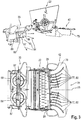
- FIG. 2 describes structural details of the combination straw chopper 22 - radial distributor 29 in side view and a view from below.
- the in the direction of the arrow 43 circulating chopper shaft 44 takes in the illustrated embodiment, four distributed over its circumference arranged rows of freely movable chopping blades 45.
- the blade 46 can be pivoted via adjusting means 47 so that the counter knife 48 received by the knife 46 further into the effective range the chopper blade 45 can be swung in or out of this.
- the change of the position of the knife or combs 46 can be influenced on the self-adjusting chop length in such a way that with increasing engagement of the counter knife 48, the crushing of the Gutstrangs 28 increases.
- the shredder wall 49 surrounding the chopping blade 45 takes up a rubbing strip 50 which is known per se and which can be further moved by means of adjusting means 51 to the circumferential circle 52 of the chopping blade 45 or moved away from it.
- the friction strip 50 has the function of decelerating the speed of the straw chopper 22 passing through Gutstrangs 28, so that increases the residence time of the Gutstranges 28 in the straw chopper 22 and thus the degree of its comminution.
- the chopper wall 49 receives a counter-blade 53, which also by means of suitable adjusting means 54 on the circumferential circle 52 of the chopper 45 zoom or can be moved away from this, the counter-blade 53 has the effect that they splice the particles of the Gutstranges 28th increases with decreasing distance to the circumferential circle 52 of the chopping blade 45.
- the downstream of the straw chopper 22 radial distributor 29 consists of two juxtaposed impeller blowers 55 which rotate around vertical axes of rotation 56 according to the arrow directions 57, 58 to each other in opposite directions and the comminuted by the straw chopper 22 Gutstrang 28 from the combine harvester 2 and in a manner to be described in more detail on distribute the soil 26.
- the axes of rotation 56 are occupied by flexible throwing blades 59, which are covered at the bottom by a co-rotating disk 60 and are closed at the top by cover plates 61.
- the two of the upper cover plates 61, the rotation axes 56, the throwing blades 59 and the co-rotating discs 60 formed blowers 55 is assigned a Guttrennblech 62, the top 63rd is directed against the ejected from the straw chopper 22 Gutstrang 28 so that it is distributed to the throwing fan 55.
- the diverging legs 64, 65 of the Guttrennbleches 62 also form with their expiring ends the fixed
- each throw fan 55 has first and second movable wall parts, so-called spreader plates 67, 68 about angle lever 69, 70 about axes of rotation 71 circumferentially driven in such a way that the outer baffle 67 precedes the inner baffle 68.
- the movable baffles 67, 68 are each driven via lifting cylinders 73 operatively connected to a coupling mechanism 72 in such a manner that the leading baffle 67 revolves at a higher speed than the trailing internal baffle 68.
- the front end of the leading scatter plate 67 forms the so-called tear-off edge 74, 75 over which the Gutstrang 28 exits from the respective radial fan 55.
- the rotational movement of the Abrisskanten 74, 75 is controlled so that their pivoting speed decreases with increasing distance of the Abrisskanten 74, 75 to the respective adjacent throwing fan 55.
- This has the effect that the tear-off edges 74, 75 have shorter residence times in their overlapping area and longer residence periods in the outer areas, so that the crop strand 28 emerging at the break-off edges 74, 75 ensures a more homogeneous distribution on the floor 26.
- the pivoting range of the demolition edges 74, 75 and thus the distribution width of the radial distributor 29 may be adjustable.
- the chaff throwing blower 32 is assigned to it.
- the chaff-throwing fan 32 receives in its interior a conveying fan 81 provided with a throwing fan 82 which is driven in rotation about a vertical axis 83.
- the lining 84 of the chaff-throwing blower 32 is designed such that it has an opening 85 pointing in the direction of the radial distributor 29, via which the chaff 34 discharged by the cleaning device 17 is conveyed into the material line 28 entering the radial distributor 29. It is within the scope of the invention that the chaff-throwing fan 32 has at least paired circulating throwing fans 82.
- FIG. 3 describes constructive details of the combination straw chopper 22 - straw discharge hood 42 in side view and bottom view. Since the straw chopper 22 after the FIG. 2 only details of the straw discharge hood 42 and the chaff spreader 33 are described here.
- the straw discharge hood 42 is formed by a covering hood 76 which forms an upper-side and lateral boundary, to which a plurality of Gutleitschienen 77 are assigned inside.
- the Gutleitschienen 77 have in relation to a central region 78 right- and left-sided alignments, so that the entering into the Strohausschaube 42 Gutstrang 28 right or left direction leaves the exit region 79 of the Strohaus schemehaube 42.
- the Gutleitschienen 77 can be formed either by flat or in their curvature changeable web plates 80. In addition, the alignment of the Gutleitschienen 77 can be adjusted in the cover hood 76 so that their cross-conveying effect is either increased or reduced.
- a chaff spreader 33 is assigned to it.
- the chaff spreader 33 receives in its interior a conveying fan 86 provided with a throwing fan 87 which is driven to rotate about a vertical axis 88.
- the covering 89 of the chaff spreader 33 is such that the chaff 34 discharged by the cleaning device 17 is distributed directly on the floor 26. It is within the scope of the invention that the chaff spreader 33 has at least paired circulating throwing fan 87.
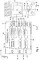
- Fig. 4 3 shows a schematic representation of the display unit 37, the control and regulating device 38 and a computing unit 90 assigned to the control and regulating device 38 and coupled to the display unit 37.
- the arithmetic unit 90 is designed in such a way that, in addition to the information 91 generated by the sensor systems 41 , external information 92 and information 93 stored in the arithmetic unit 90, such as expert knowledge, can process a multiplicity of output signals 94.
- the output signals 94 are designed such that they comprise at least display control signals 95 and work organ control signals 96.
- the former determine the contents of the display unit 37 and the latter effect according to the invention the change of the most diverse working organ parameters 97 of the agricultural Work machine 1, such as the speed n HW of the chopper shaft 44, with the aim to achieve a homogeneous distribution of emerging from the combine harvester 2 Gutstrangs 28 on the ground 26.
- the control and regulating device 38 with its associated display unit 37 and the arithmetic unit 90 are part of the driver assistance system 98 according to the invention.
- the driver assistance system 98 is designed as a so-called chopping and distribution machine 99, which optimizes the distribution of the crop 28 on the ground 26.
- the driver assistance system 98 is designed such that it comprises distribution strategies 100 that can be selected and edited to control the distribution of the crop 2 exiting the combine harvester 2, wherein each distribution strategy 100 is assigned to substrategies 101, so that when one distribution strategy 100 is selected one or more are involved the selected distribution strategy 100 coupled partial strategies 101 are processed. It is first within the scope of the invention that either the operator 39 or the driver assistance system 98 select a distribution strategy 100 and / or partial strategy 101 to be processed or a combination of a plurality of distribution strategies 100 and / or multiple partial strategies 101. If the display unit 37 is designed as a touch screen in this context, the operator 39 can, in a particularly simple case, effect the selection of a suitable strategy 100, 101 by touching the respective field on the touchscreen.
- a further menu field 104 can be opened in which the distribution strategies 100 and the associated substrategies 101 can then be selected directly. It is also conceivable that the respective strategies 100, 101 are selected by actuation of keys 105 assigned to the display unit 37.
- a particularly efficient optimization of the distribution is achieved when the selectable distribution strategies 100 comprise at least one or more of the distribution strategies "uniform distribution of goods" 106, "shred quality” 107 and "energy efficiency” 108.
- the distribution strategy "uniform material distribution” 106 thereby optimizes the distribution of the crop 28 on the ground 26.
- the distribution strategy "chopping quality” 107 leads to an optimization of the Comminution of the Gutstranges 28 in the crushing device 23, while the distribution strategy "energy efficiency” 108 causes an optimization of the energy requirements for the crushing and distribution of the Gutstranges 28.
- a distribution strategy 106-108 and its respectively associated partial strategies 101 or a combination of several distribution and partial strategies 106-108, 101 are selected by the driver 39 of the combine harvester 2 or proposed by the driver assistance system 98.
- Each of the distribution strategies 106-108 and the partial strategies 101 according to the invention to be explained below take into account a multiplicity of the information 91-93 accessible in the driver assistance system 98, this information including at least the information "throughput parameter” 109, "material or casting properties” 110, "machine parameter 111 and "ambient conditions” 112.
- the throughput-dependent influence on the distribution of the Gutstrangs 28 on the ground 26 is then detected sufficiently well if the information "flow rate parameter" 109 one or more of the flow rate relevant parameters 113 grain throughput, layer height in a combine harvester 2 associated inclined conveyor 4, drive motor utilization, drive power demand of the crushing device 23, drive power requirement of the distribution devices radial distributor 29, spreader 31 and / or ejection hood 42 and / or transverse and longitudinal distribution of the Gutstrangs 28 in the crushing device 23 includes.
- the property property-dependent influence on the distribution of good on the ground 26 is then detected well if the information "material and throwing properties" 110 comprises one or more of the property properties relevant to straw moisture, chop length, splice, crop density, toughness and crop type.
- the machine parameter-dependent influence on the distribution which is related to the comminuting device 23, is then detected sufficiently well if the Crushing device 23 is designed as a straw chopper 22 and the Gutstrang 28 is shredded in the straw chopper 22 in cooperation of rotating chopping blades 45 with fixed counter knives 46, one or more counter knives 53 and one or more friction bars 50 and the information "machine parameters" 111 one or more of the machine-relevant Parameter 115 Number and position of the friction strips 50, the counter blade 48, the counter blades 53 and wear parameters of the chopping blades 45 and speed parameters of the chopper shaft 44 includes.
- the distributor device is designed as a radial distributor 29 which comprises at least deflectable scattering plates 67, 68 and one or more discharge fans 55, then the machine parameter-dependent influence on the distribution of the material strand 28 on the base 26 is detected sufficiently well if the information "machine parameters" 111 is one or more several of the machine-relevant parameters 115 deflection, pendulum frequency and distribution curve of the scattering plates 67, 68, speed parameters of the throwing fan 55 and upstream circulating working elements of the combine harvester 2 includes.
- the machine-relevant parameter 115 comprises at least the rotational speed of the spreader fan 32 or spreader distributor 33 assigned to the spreader fan 82, 87. If the distribution line 28 distributing the product strand 28 on the ground 26 as ejection hood occupied with Gutleitschienen 77 ejector 42, the machine-relevant parameter 115 comprises at least the alignment of the Gutleitschienen 77 in the ejection hood 42nd
- the information "ambient conditions" 112 includes one or more of the environmental parameters 116 air humidity and air temperature parameters, wind parameters such as wind speed and wind direction and slope parameters.
- the driver assistance system 98 in a next menu step 117 operates the respective distribution strategy 100 and the associated distribution strategy at least one sub-strategy 101, taking into account the available information 118 and stored in the arithmetic unit 90 characteristics 119, so that finally results in an optimization of the quality criteria distribution of goods 120a, chaff quality 120b and energy needs 120c.
- the quality criterion 120a-c optimized by the respective distribution strategy 106-108 and assigned thereto by at least one partial strategy 101 is checked, with the check taking place directly and indirectly.
- the result is recorded directly by torque and / or speed and / or engine utilization measurement.
- the indirect detection is carried out by processing an energy efficiency model 123 stored in the arithmetic unit 90, the energy efficiency model 123, in analogy to the chopping quality model 122, varying the drive energy requirement as a function of crop properties.
- the optimization of the quality parameters chaff quality 120b and energy requirement 120c can also be further improved by the distribution strategies "chopping quality” 107 and "energy efficiency” 108 stored in the driver assistance system 98 as well as the inventive systems assigned to them Substrategies 101 are combined or accounted for together.
- the background is that the quality parameters chaff quality 120b and energy demand 120c have opposite tendencies, since the finer the material strand 28 is the comminution of a fast decomposition, the higher the energy requirement.
- step 125 the driver assistance system 98 finally, taking into account the specifications of the operator 39 and the stored characteristics 119, 122, 123, a change of machine parameters 111.
- the optimization process in the manner of a control loop 126 can be repeated cyclically, the cyclic repetition either automatically or is triggered by the operator 39.
- FIG. 6 shows the relationships stored in the distribution strategies 100 according to the invention and the sub-strategies 101 assigned to them in each case by way of example in a specific application.
- the distribution strategy "uniform distribution of goods" 106 according to the invention is such that it can comprise a plurality of partial strategies 101.
- the mass of the proportionate Gutstranges 28 exiting from the spreading device 127 designed as a spreader device 31, radial distributor 29 or ejection hood 42 and the surface portion 128 of the bottom 26 on which the sensed portion of the Gutstranges 28 is distributed is measured and from this is the Good distribution 129 on the area ratio 128 of the bottom 26 determined.
- the amount of leaking Gutstranges 28 and the associated surface portion 128 can be detected in a known per se and therefore not further explained manner by means of suitable, on the agricultural machine 1 positioned camera systems 130.
- the machined surface portion 132 is determined as a function of the travel speed vf and the part width utilization 131 of the combine 2 associated with the combine harvester and the distribution of the exiting product strand 28 is limited to this area portion 132 of the bottom 26. This has the advantage that the emerging Gutstrang 28 is distributed only where was harvested. It is within the scope of the invention that the machined surface portion 132 can be determined by camera systems 130 positioned on the combine harvester 2 at the front.
- a partial strategy 101 may also be such that the throughput 133 and its transverse distribution 134 are determined by means of suitable sensors known per se in the combine harvester 2 and the discharge direction and / or speed 135 of the crop strand 28 from the respective distribution device 127 as a function of the determined throughput 133 and the determined lateral distribution 134 are regulated.
- Another sub-strategy 101 may be directed to determining the vehicle speed vf in relation to the throughput-dependent vehicle speed change ⁇ vf and to control the discharge direction and / or speed 135 of the product line 28 as a function of the detected vehicle speed change ⁇ vf. This is advantageous if a so-called cruise control is used which sets a constant flow rate 133 by adjusting the travel speed vf of the agricultural work machine 1.
- At least the wind parameters 136 wind speed, wind speed, wind direction are sensed in a manner known per se, and the discharge direction and / or speed 135 of the Gutstranges 28 is adjusted as a function of the detected wind parameters 136.
- the slope angle can be determined in a further sub-strategy 101 and the discharge direction and / or speed 135 of the crop line 28 can be regulated as a function of the detected slope be, with the uphill to be promoted Good share in comparison to the slope to be promoted Good share must increase.
- Another sub-strategy 101 may be such that, depending on the determined straw moisture 137, a change in the discharge direction and / or speed 135 of the crop strand 28 is effected.
- the moisture-dependent changing aerodynamic properties of the emerging Gutstranges 28 are better taken into account. For example, increases with increasing straw moisture 137, the friction between the Gutstrang 28 and the guide elements of an ejector hood 42, so that the throwing distance of the emerging Gutstranges decreases while the throw increases with distribution by means of radial distributor 29 with increasing Gutfeuchte 137. In both cases, it is necessary to counteract, so as to ensure that the emerging product strand 28 is evenly distributed on the ground 26 and in particular on the respective surface portion 132.
- a particularly advantageous embodiment of the invention results if the partial strategy 101 directed to the straw moisture 137 increases the pendulum frequency of the scattering plates 67, 68 with increasing straw moisture 137.
- the distribution strategy "chopping quality" 107 is also such that it can comprise a plurality of partial strategies 101.
- the partial strategies 101 assigned to the "chopping quality" distribution strategy 107 can be such that they include a stepped pivoting of the counter knives 48 and / or the pivoting of the friction strip 50.
- the degree of comminution of the Gutstranges 28 increases with increasing engagement of the counter blade 48 in the circumferential circle 52 of the chopping blade 45.
- the same effect occurs when the friction strip 50 is closer to the circumferential circle 52 of the Chopping knife 45 is introduced.
- the reason for this is that the friction between Gutstrang 28 and friction strip 50 increases with increasing engagement of the friction strip 50 in the Gutstrang 28 and thereby increases the residence time of the estate Ruts 28 in the straw chopper 22.
- the distribution strategy "energy efficiency" 108 is analogous in that it may comprise a plurality of partial strategies 101. A significant reduction of the energy requirement is ensured if in a first partial strategy 101 a stepped swinging of the counter blades 48 and / or a swinging of the friction strip 50 are effected. By reducing either the comminution effect or the friction between Gutstrang 28 and friction bar 50, the energy requirement decreases.
- a further sub-strategy 101 may in this context be such that the rotting suitability of the gutter 28 to be distributed on the ground 26 is determined and a required chopping length is set in the comminution device 22 as a function of the ascertained rotting suitability, whereby in the simplest case Swinging in or out of the counter blade 48 and / or the friction strip 50 is effected.
- a sub-strategy 101 may also be such that the longer the chopper suitability is, the longer the chop length is set.
- the chop length can be changed depending on the detected straw moisture 137 in such a way that with increasing straw moisture 137 a larger chop length is set, on the one hand, the negative influence of the decreasing Gutfeuchte on the throw can be compensated by increasing the particle size and On the other hand, a reduction of the necessary crushing energy can be achieved.
- the driver assistance system 98 can also be designed such that it contains one or more of the influencing variables rotational speed of the comminuting device 23, rotational speed of the main drive of the agricultural vehicle Anlagenmaschien 1, the Gut carefullysatz 133, material properties of the Gutstranges 28, transverse and longitudinal distribution in the straw chopper 22 and Reibleists-, counter knife and counter cutting parameters are taken into account.
- one or more of the partial strategies 101 effecting the regulation of the distribution of the crop strand 28 emerging from the combine harvester 2 are stored in the characteristic units 119 in the arithmetic unit 90.
Applications Claiming Priority (1)
| Application Number | Priority Date | Filing Date | Title |
|---|---|---|---|
| DE102016118187.0A DE102016118187A1 (de) | 2016-09-27 | 2016-09-27 | Mähdrescher mit Fahrerassistenzsystem |
Publications (2)
| Publication Number | Publication Date |
|---|---|
| EP3298880A1 true EP3298880A1 (fr) | 2018-03-28 |
| EP3298880B1 EP3298880B1 (fr) | 2020-11-04 |
Family
ID=58632877
Family Applications (1)
| Application Number | Title | Priority Date | Filing Date |
|---|---|---|---|
| EP17168174.5A Active EP3298880B1 (fr) | 2016-09-27 | 2017-04-26 | Moissonneuse-batteuse dotée d'un système d'assistance du conducteur |
Country Status (3)
| Country | Link |
|---|---|
| US (1) | US10362732B2 (fr) |
| EP (1) | EP3298880B1 (fr) |
| DE (1) | DE102016118187A1 (fr) |
Cited By (1)
| Publication number | Priority date | Publication date | Assignee | Title |
|---|---|---|---|---|
| EP3395158A1 (fr) * | 2017-04-25 | 2018-10-31 | CLAAS Selbstfahrende Erntemaschinen GmbH | Moissonneuse-batteuse |
Families Citing this family (23)
| Publication number | Priority date | Publication date | Assignee | Title |
|---|---|---|---|---|
| BE1022889B1 (nl) * | 2015-05-29 | 2016-10-07 | Cnh Industrial Belgium Nv | controller voor een oogstmachine |
| DE102015118767A1 (de) * | 2015-11-03 | 2017-05-04 | Claas Selbstfahrende Erntemaschinen Gmbh | Umfelddetektionseinrichtung für landwirtschaftliche Arbeitsmaschine |
| CN106561172B (zh) * | 2016-10-25 | 2019-01-08 | 江苏大学 | 一种纵轴流联合收获机排草粉碎自适应抛撒装置及其控制方法 |
| BE1025041B1 (nl) * | 2017-03-09 | 2018-10-11 | Cnh Industrial Belgium Nv | Controlesysteem voor een oogstmachine en oogstmachine |
| US10952374B2 (en) * | 2017-05-01 | 2021-03-23 | Cnh Industrial America Llc | System and method for monitoring residue output from a harvester |
| US10674671B2 (en) * | 2017-12-08 | 2020-06-09 | Cnh Industrial America Llc | Auxiliary processing system |
| US11019768B2 (en) * | 2018-02-26 | 2021-06-01 | Deere & Company | Double decker crop residue spreader |
| DE102018212075A1 (de) * | 2018-07-19 | 2020-01-23 | Deere & Company | Mähdrescher mit einem Schrägförderer mit aktorisch verstellbarer, unterer Umlenkwalze |
| DE102018120651A1 (de) | 2018-08-23 | 2020-02-27 | Claas Selbstfahrende Erntemaschinen Gmbh | Mähdrescher |
| DE102018120741A1 (de) * | 2018-08-24 | 2020-02-27 | Claas Selbstfahrende Erntemaschinen Gmbh | Mähdrescher |
| DE102018121031A1 (de) * | 2018-08-29 | 2020-03-05 | Claas Selbstfahrende Erntemaschinen Gmbh | Landwirtschaftliche Arbeitsmaschine |
| US20200120869A1 (en) * | 2018-10-19 | 2020-04-23 | Deere & Company | Residue spread monitoring |
| US11369058B2 (en) | 2019-03-19 | 2022-06-28 | Deere & Company | Forward-looking perception interface and control |
| US11758847B2 (en) | 2019-09-19 | 2023-09-19 | Deere & Company | Residue quality assessment and performance system for a harvester |
| DE102019125645A1 (de) * | 2019-09-24 | 2021-03-25 | Claas Selbstfahrende Erntemaschinen Gmbh | Mähdrescher mit Restkornsensor |
| GB201917035D0 (en) * | 2019-11-22 | 2020-01-08 | Agco Int Gmbh | Tailboard arrangement |
| WO2021099633A1 (fr) * | 2019-11-22 | 2021-05-27 | Agco International Gmbh | Épandeur de résidus pour une moissonneuse-batteuse |
| DE102020108083A1 (de) | 2020-03-24 | 2021-09-30 | Claas Selbstfahrende Erntemaschinen Gmbh | Verfahren zum Betrieb eines selbstfahrenden Mähdreschers sowie selbstfahrender Mähdrescher |
| DE102020108089A1 (de) | 2020-03-24 | 2021-09-30 | Claas Selbstfahrende Erntemaschinen Gmbh | Verfahren zum Betrieb eines selbstfahrenden Mähdreschers sowie selbstfahrender Mähdrescher |
| EP4201194A3 (fr) * | 2020-08-27 | 2023-11-15 | Agco Corporation | Réglage automatique de la vitesse de tracteur pour éviter l'obturation de la presse à balles |
| CN112804452B (zh) * | 2021-01-06 | 2022-08-12 | 华南农业大学 | 一种基于高杆作物的智能表型采集小车和采集方法 |
| US20220232772A1 (en) * | 2021-01-22 | 2022-07-28 | Deere & Company | Residue management control system for harvester |
| CN113534182A (zh) * | 2021-05-27 | 2021-10-22 | 北京农业智能装备技术研究中心 | 秸秆打捆作物行检测方法、设备及存储介质 |
Citations (7)
| Publication number | Priority date | Publication date | Assignee | Title |
|---|---|---|---|---|
| EP0685151A1 (fr) | 1994-06-03 | 1995-12-06 | CLAAS KGaA | Dispositif à répartir pour hacheur |
| DE10147733A1 (de) | 2001-09-27 | 2003-04-10 | Claas Selbstfahr Erntemasch | Verfahren und Vorrichtung zur Ermittlung einer Erntemaschineneinstellung |
| EP1514466A2 (fr) | 2003-09-15 | 2005-03-16 | CLAAS Selbstfahrende Erntemaschinen GmbH | Dispositif de coupe et de distribution |
| EP1790207A1 (fr) | 2005-11-25 | 2007-05-30 | CLAAS Selbstfahrende Erntemaschinen GmbH | Dispositif de distribution pour flux de produits |
| EP2712754A1 (fr) * | 2012-09-27 | 2014-04-02 | CLAAS Selbstfahrende Erntemaschinen GmbH | Procédé de fonctionnement d'une machine de travail agricole |
| WO2014118239A1 (fr) * | 2013-01-30 | 2014-08-07 | Cnh Industrial Belgium Nv | Mécanisme de guidage d'une machine de récolte |
| EP3000303A1 (fr) * | 2014-09-26 | 2016-03-30 | CLAAS Selbstfahrende Erntemaschinen GmbH | Moissonneuse-batteuse dote d'un systeme d'assistance du conducteur |
Family Cites Families (9)
| Publication number | Priority date | Publication date | Assignee | Title |
|---|---|---|---|---|
| DE4218235A1 (de) | 1992-06-03 | 1993-12-09 | Kloeckner Humboldt Deutz Ag | Strohverteilung am Mähdrescher |
| DE102006026041A1 (de) | 2006-06-01 | 2007-12-20 | Claas Selbstfahrende Erntemaschinen Gmbh | Verteilvorrichtung zum Verteilen von aus einer Erntemaschine austretendem Erntegut |
| US8463510B2 (en) | 2010-04-30 | 2013-06-11 | Cnh America Llc | GPS controlled residue spread width |
| DE102011000057A1 (de) | 2011-01-07 | 2012-07-12 | Claas Selbstfahrende Erntemaschinen Gmbh | Mähdrescher mit einer Verteilvorrichtung zur Verteilung gehäckselten Erntegutes |
| US9107345B2 (en) * | 2013-05-01 | 2015-08-18 | Cnh Industrial America Llc | Method of remotely configuring a residue system of an agricultural harvester |
| DE102013108292A1 (de) | 2013-08-01 | 2015-02-05 | Claas Selbstfahrende Erntemaschinen Gmbh | Mähdrescher mit einer Häckselvorrichtung |
| DE102014005906A1 (de) | 2014-04-25 | 2015-10-29 | Claas Selbstfahrende Erntemaschinen Gmbh | Fahrzeug mit Streugutverteilvorrichtung |
| US9497903B2 (en) * | 2014-10-16 | 2016-11-22 | Agco Corporation | Combine harvester residue management system |
| BE1022730B1 (nl) * | 2015-01-05 | 2016-08-25 | Cnh Industrial Belgium Nv | Restantenontlaadsysteem voor een maaidorser met een afdekgeheel |
-
2016
- 2016-09-27 DE DE102016118187.0A patent/DE102016118187A1/de active Pending
-
2017
- 2017-04-26 EP EP17168174.5A patent/EP3298880B1/fr active Active
- 2017-09-05 US US15/695,482 patent/US10362732B2/en active Active
Patent Citations (8)
| Publication number | Priority date | Publication date | Assignee | Title |
|---|---|---|---|---|
| EP0685151A1 (fr) | 1994-06-03 | 1995-12-06 | CLAAS KGaA | Dispositif à répartir pour hacheur |
| DE10147733A1 (de) | 2001-09-27 | 2003-04-10 | Claas Selbstfahr Erntemasch | Verfahren und Vorrichtung zur Ermittlung einer Erntemaschineneinstellung |
| EP1514466A2 (fr) | 2003-09-15 | 2005-03-16 | CLAAS Selbstfahrende Erntemaschinen GmbH | Dispositif de coupe et de distribution |
| EP1790207A1 (fr) | 2005-11-25 | 2007-05-30 | CLAAS Selbstfahrende Erntemaschinen GmbH | Dispositif de distribution pour flux de produits |
| EP2712754A1 (fr) * | 2012-09-27 | 2014-04-02 | CLAAS Selbstfahrende Erntemaschinen GmbH | Procédé de fonctionnement d'une machine de travail agricole |
| WO2014118239A1 (fr) * | 2013-01-30 | 2014-08-07 | Cnh Industrial Belgium Nv | Mécanisme de guidage d'une machine de récolte |
| EP3000303A1 (fr) * | 2014-09-26 | 2016-03-30 | CLAAS Selbstfahrende Erntemaschinen GmbH | Moissonneuse-batteuse dote d'un systeme d'assistance du conducteur |
| DE102014113965A1 (de) | 2014-09-26 | 2016-03-31 | Claas Selbstfahrende Erntemaschinen Gmbh | Mähdrescher mit Fahrerassistenzsystem |
Cited By (2)
| Publication number | Priority date | Publication date | Assignee | Title |
|---|---|---|---|---|
| EP3395158A1 (fr) * | 2017-04-25 | 2018-10-31 | CLAAS Selbstfahrende Erntemaschinen GmbH | Moissonneuse-batteuse |
| US10492364B2 (en) | 2017-04-25 | 2019-12-03 | Claas Selbstfahrende Erntemaschinen Gmbh | Combine harvester |
Also Published As
| Publication number | Publication date |
|---|---|
| US10362732B2 (en) | 2019-07-30 |
| DE102016118187A1 (de) | 2018-03-29 |
| EP3298880B1 (fr) | 2020-11-04 |
| US20180084718A1 (en) | 2018-03-29 |
Similar Documents
| Publication | Publication Date | Title |
|---|---|---|
| EP3298880B1 (fr) | Moissonneuse-batteuse dotée d'un système d'assistance du conducteur | |
| EP3000303B1 (fr) | Moissonneuse-batteuse dote d'un systeme d'assistance du conducteur | |
| EP3662741B1 (fr) | Machine de travail agricole ainsi que procédé de fonctionnement d'une machine de travail agricole | |
| EP3395158B1 (fr) | Moissonneuse-batteuse | |
| DE602004005553T2 (de) | System zum Ausstossen von Ernteresten aus einem Mähdrescher | |
| EP1350424B1 (fr) | Moisonneuse-batteuse avec dispositif de guidage de paille motorisé ajustable | |
| EP2298061B1 (fr) | Procédé de répartition d'un flux de matière sur un champ et dispositif de hachage et de répartition | |
| EP1493318B1 (fr) | Procédé de control d'un ensemble de battage pour moissonneuse-batteuse | |
| DE60108654T2 (de) | Mähdrescher | |
| EP1219164B1 (fr) | Procédé et dispositif pour convoyer des récoltes dans une machine agricole | |
| EP2452550B1 (fr) | Moissonneuse agricole | |
| DE60317168T2 (de) | Spreuverteiler für mähdrescher | |
| EP3662738B1 (fr) | Moissonneuse-batteuse automotrice | |
| EP2364587B1 (fr) | Séparateur axial pour une moissonneuse-batteuse | |
| EP1897430B1 (fr) | Dispositif de hachage et de répartition | |
| DE10063550B4 (de) | Mähdrescher mit Häckseleinrichtung | |
| EP3662737B1 (fr) | Moissonneuse-batteuse automotrice | |
| DE102006026041A1 (de) | Verteilvorrichtung zum Verteilen von aus einer Erntemaschine austretendem Erntegut | |
| DE102020123939A1 (de) | Rotierender siebkasten | |
| DE102006023381A1 (de) | Verfahren und Vorrichtung zum Betreiben einer Erntegutzerkleinerungs- und -verteilvorrichtung | |
| DE102021125821A1 (de) | Häcksler mit beweglicher auslassbodenrampe | |
| EP3909416B1 (fr) | Ramasseuse-hacheuse dotée d'un canal de transport permettant de transporter le produit de la récolte et procédé de transport du produit de la récolte | |
| EP2130425A1 (fr) | Agencement de tambour de hachage | |
| EP2181578A2 (fr) | Moissonneuse-batteuse et procédé de récolte | |
| DE102022123913A1 (de) | Mähdrescher mit Zerkleinerungseinrichtung |
Legal Events
| Date | Code | Title | Description |
|---|---|---|---|
| PUAI | Public reference made under article 153(3) epc to a published international application that has entered the european phase |
Free format text: ORIGINAL CODE: 0009012 |
|
| STAA | Information on the status of an ep patent application or granted ep patent |
Free format text: STATUS: THE APPLICATION HAS BEEN PUBLISHED |
|
| AK | Designated contracting states |
Kind code of ref document: A1 Designated state(s): AL AT BE BG CH CY CZ DE DK EE ES FI FR GB GR HR HU IE IS IT LI LT LU LV MC MK MT NL NO PL PT RO RS SE SI SK SM TR |
|
| AX | Request for extension of the european patent |
Extension state: BA ME |
|
| STAA | Information on the status of an ep patent application or granted ep patent |
Free format text: STATUS: REQUEST FOR EXAMINATION WAS MADE |
|
| 17P | Request for examination filed |
Effective date: 20180928 |
|
| RBV | Designated contracting states (corrected) |
Designated state(s): AL AT BE BG CH CY CZ DE DK EE ES FI FR GB GR HR HU IE IS IT LI LT LU LV MC MK MT NL NO PL PT RO RS SE SI SK SM TR |
|
| GRAP | Despatch of communication of intention to grant a patent |
Free format text: ORIGINAL CODE: EPIDOSNIGR1 |
|
| STAA | Information on the status of an ep patent application or granted ep patent |
Free format text: STATUS: GRANT OF PATENT IS INTENDED |
|
| INTG | Intention to grant announced |
Effective date: 20200714 |
|
| GRAS | Grant fee paid |
Free format text: ORIGINAL CODE: EPIDOSNIGR3 |
|
| GRAA | (expected) grant |
Free format text: ORIGINAL CODE: 0009210 |
|
| STAA | Information on the status of an ep patent application or granted ep patent |
Free format text: STATUS: THE PATENT HAS BEEN GRANTED |
|
| AK | Designated contracting states |
Kind code of ref document: B1 Designated state(s): AL AT BE BG CH CY CZ DE DK EE ES FI FR GB GR HR HU IE IS IT LI LT LU LV MC MK MT NL NO PL PT RO RS SE SI SK SM TR |
|
| REG | Reference to a national code |
Ref country code: GB Ref legal event code: FG4D Free format text: NOT ENGLISH |
|
| REG | Reference to a national code |
Ref country code: CH Ref legal event code: EP |
|
| REG | Reference to a national code |
Ref country code: AT Ref legal event code: REF Ref document number: 1329608 Country of ref document: AT Kind code of ref document: T Effective date: 20201115 |
|
| REG | Reference to a national code |
Ref country code: IE Ref legal event code: FG4D Free format text: LANGUAGE OF EP DOCUMENT: GERMAN |
|
| REG | Reference to a national code |
Ref country code: DE Ref legal event code: R096 Ref document number: 502017007994 Country of ref document: DE |
|
| REG | Reference to a national code |
Ref country code: NL Ref legal event code: MP Effective date: 20201104 |
|
| PG25 | Lapsed in a contracting state [announced via postgrant information from national office to epo] |
Ref country code: FI Free format text: LAPSE BECAUSE OF FAILURE TO SUBMIT A TRANSLATION OF THE DESCRIPTION OR TO PAY THE FEE WITHIN THE PRESCRIBED TIME-LIMIT Effective date: 20201104 Ref country code: GR Free format text: LAPSE BECAUSE OF FAILURE TO SUBMIT A TRANSLATION OF THE DESCRIPTION OR TO PAY THE FEE WITHIN THE PRESCRIBED TIME-LIMIT Effective date: 20210205 Ref country code: PT Free format text: LAPSE BECAUSE OF FAILURE TO SUBMIT A TRANSLATION OF THE DESCRIPTION OR TO PAY THE FEE WITHIN THE PRESCRIBED TIME-LIMIT Effective date: 20210304 Ref country code: RS Free format text: LAPSE BECAUSE OF FAILURE TO SUBMIT A TRANSLATION OF THE DESCRIPTION OR TO PAY THE FEE WITHIN THE PRESCRIBED TIME-LIMIT Effective date: 20201104 Ref country code: NO Free format text: LAPSE BECAUSE OF FAILURE TO SUBMIT A TRANSLATION OF THE DESCRIPTION OR TO PAY THE FEE WITHIN THE PRESCRIBED TIME-LIMIT Effective date: 20210204 |
|
| PG25 | Lapsed in a contracting state [announced via postgrant information from national office to epo] |
Ref country code: SE Free format text: LAPSE BECAUSE OF FAILURE TO SUBMIT A TRANSLATION OF THE DESCRIPTION OR TO PAY THE FEE WITHIN THE PRESCRIBED TIME-LIMIT Effective date: 20201104 Ref country code: ES Free format text: LAPSE BECAUSE OF FAILURE TO SUBMIT A TRANSLATION OF THE DESCRIPTION OR TO PAY THE FEE WITHIN THE PRESCRIBED TIME-LIMIT Effective date: 20201104 Ref country code: LV Free format text: LAPSE BECAUSE OF FAILURE TO SUBMIT A TRANSLATION OF THE DESCRIPTION OR TO PAY THE FEE WITHIN THE PRESCRIBED TIME-LIMIT Effective date: 20201104 Ref country code: PL Free format text: LAPSE BECAUSE OF FAILURE TO SUBMIT A TRANSLATION OF THE DESCRIPTION OR TO PAY THE FEE WITHIN THE PRESCRIBED TIME-LIMIT Effective date: 20201104 Ref country code: IS Free format text: LAPSE BECAUSE OF FAILURE TO SUBMIT A TRANSLATION OF THE DESCRIPTION OR TO PAY THE FEE WITHIN THE PRESCRIBED TIME-LIMIT Effective date: 20210304 Ref country code: BG Free format text: LAPSE BECAUSE OF FAILURE TO SUBMIT A TRANSLATION OF THE DESCRIPTION OR TO PAY THE FEE WITHIN THE PRESCRIBED TIME-LIMIT Effective date: 20210204 |
|
| REG | Reference to a national code |
Ref country code: LT Ref legal event code: MG9D |
|
| PG25 | Lapsed in a contracting state [announced via postgrant information from national office to epo] |
Ref country code: HR Free format text: LAPSE BECAUSE OF FAILURE TO SUBMIT A TRANSLATION OF THE DESCRIPTION OR TO PAY THE FEE WITHIN THE PRESCRIBED TIME-LIMIT Effective date: 20201104 |
|
| REG | Reference to a national code |
Ref country code: DE Ref legal event code: R026 Ref document number: 502017007994 Country of ref document: DE |
|
| PLBI | Opposition filed |
Free format text: ORIGINAL CODE: 0009260 |
|
| PG25 | Lapsed in a contracting state [announced via postgrant information from national office to epo] |
Ref country code: CZ Free format text: LAPSE BECAUSE OF FAILURE TO SUBMIT A TRANSLATION OF THE DESCRIPTION OR TO PAY THE FEE WITHIN THE PRESCRIBED TIME-LIMIT Effective date: 20201104 Ref country code: EE Free format text: LAPSE BECAUSE OF FAILURE TO SUBMIT A TRANSLATION OF THE DESCRIPTION OR TO PAY THE FEE WITHIN THE PRESCRIBED TIME-LIMIT Effective date: 20201104 Ref country code: LT Free format text: LAPSE BECAUSE OF FAILURE TO SUBMIT A TRANSLATION OF THE DESCRIPTION OR TO PAY THE FEE WITHIN THE PRESCRIBED TIME-LIMIT Effective date: 20201104 Ref country code: SM Free format text: LAPSE BECAUSE OF FAILURE TO SUBMIT A TRANSLATION OF THE DESCRIPTION OR TO PAY THE FEE WITHIN THE PRESCRIBED TIME-LIMIT Effective date: 20201104 Ref country code: SK Free format text: LAPSE BECAUSE OF FAILURE TO SUBMIT A TRANSLATION OF THE DESCRIPTION OR TO PAY THE FEE WITHIN THE PRESCRIBED TIME-LIMIT Effective date: 20201104 Ref country code: RO Free format text: LAPSE BECAUSE OF FAILURE TO SUBMIT A TRANSLATION OF THE DESCRIPTION OR TO PAY THE FEE WITHIN THE PRESCRIBED TIME-LIMIT Effective date: 20201104 |
|
| PLAX | Notice of opposition and request to file observation + time limit sent |
Free format text: ORIGINAL CODE: EPIDOSNOBS2 |
|
| 26 | Opposition filed |
Opponent name: DEERE & COMPANY/JOHN DEERE GMBH & CO. KG Effective date: 20210714 |
|
| PG25 | Lapsed in a contracting state [announced via postgrant information from national office to epo] |
Ref country code: DK Free format text: LAPSE BECAUSE OF FAILURE TO SUBMIT A TRANSLATION OF THE DESCRIPTION OR TO PAY THE FEE WITHIN THE PRESCRIBED TIME-LIMIT Effective date: 20201104 |
|
| PG25 | Lapsed in a contracting state [announced via postgrant information from national office to epo] |
Ref country code: NL Free format text: LAPSE BECAUSE OF FAILURE TO SUBMIT A TRANSLATION OF THE DESCRIPTION OR TO PAY THE FEE WITHIN THE PRESCRIBED TIME-LIMIT Effective date: 20201104 Ref country code: AL Free format text: LAPSE BECAUSE OF FAILURE TO SUBMIT A TRANSLATION OF THE DESCRIPTION OR TO PAY THE FEE WITHIN THE PRESCRIBED TIME-LIMIT Effective date: 20201104 |
|
| PLBB | Reply of patent proprietor to notice(s) of opposition received |
Free format text: ORIGINAL CODE: EPIDOSNOBS3 |
|
| PG25 | Lapsed in a contracting state [announced via postgrant information from national office to epo] |
Ref country code: SI Free format text: LAPSE BECAUSE OF FAILURE TO SUBMIT A TRANSLATION OF THE DESCRIPTION OR TO PAY THE FEE WITHIN THE PRESCRIBED TIME-LIMIT Effective date: 20201104 Ref country code: MC Free format text: LAPSE BECAUSE OF FAILURE TO SUBMIT A TRANSLATION OF THE DESCRIPTION OR TO PAY THE FEE WITHIN THE PRESCRIBED TIME-LIMIT Effective date: 20201104 |
|
| GBPC | Gb: european patent ceased through non-payment of renewal fee |
Effective date: 20210426 |
|
| PG25 | Lapsed in a contracting state [announced via postgrant information from national office to epo] |
Ref country code: LU Free format text: LAPSE BECAUSE OF NON-PAYMENT OF DUE FEES Effective date: 20210426 |
|
| PG25 | Lapsed in a contracting state [announced via postgrant information from national office to epo] |
Ref country code: GB Free format text: LAPSE BECAUSE OF NON-PAYMENT OF DUE FEES Effective date: 20210426 Ref country code: CH Free format text: LAPSE BECAUSE OF NON-PAYMENT OF DUE FEES Effective date: 20210430 Ref country code: LI Free format text: LAPSE BECAUSE OF NON-PAYMENT OF DUE FEES Effective date: 20210430 |
|
| PG25 | Lapsed in a contracting state [announced via postgrant information from national office to epo] |
Ref country code: IE Free format text: LAPSE BECAUSE OF NON-PAYMENT OF DUE FEES Effective date: 20210426 |
|
| PG25 | Lapsed in a contracting state [announced via postgrant information from national office to epo] |
Ref country code: IS Free format text: LAPSE BECAUSE OF FAILURE TO SUBMIT A TRANSLATION OF THE DESCRIPTION OR TO PAY THE FEE WITHIN THE PRESCRIBED TIME-LIMIT Effective date: 20210304 |
|
| RDAF | Communication despatched that patent is revoked |
Free format text: ORIGINAL CODE: EPIDOSNREV1 |
|
| APAH | Appeal reference modified |
Free format text: ORIGINAL CODE: EPIDOSCREFNO |
|
| APAW | Appeal reference deleted |
Free format text: ORIGINAL CODE: EPIDOSDREFNO |
|
| APAY | Date of receipt of notice of appeal deleted |
Free format text: ORIGINAL CODE: EPIDOSDNOA2O |
|
| APBM | Appeal reference recorded |
Free format text: ORIGINAL CODE: EPIDOSNREFNO |
|
| APBP | Date of receipt of notice of appeal recorded |
Free format text: ORIGINAL CODE: EPIDOSNNOA2O |
|
| APBQ | Date of receipt of statement of grounds of appeal recorded |
Free format text: ORIGINAL CODE: EPIDOSNNOA3O |
|
| PG25 | Lapsed in a contracting state [announced via postgrant information from national office to epo] |
Ref country code: HU Free format text: LAPSE BECAUSE OF FAILURE TO SUBMIT A TRANSLATION OF THE DESCRIPTION OR TO PAY THE FEE WITHIN THE PRESCRIBED TIME-LIMIT; INVALID AB INITIO Effective date: 20170426 |
|
| REG | Reference to a national code |
Ref country code: AT Ref legal event code: MM01 Ref document number: 1329608 Country of ref document: AT Kind code of ref document: T Effective date: 20220426 |
|
| P01 | Opt-out of the competence of the unified patent court (upc) registered |
Effective date: 20230516 |
|
| PG25 | Lapsed in a contracting state [announced via postgrant information from national office to epo] |
Ref country code: CY Free format text: LAPSE BECAUSE OF FAILURE TO SUBMIT A TRANSLATION OF THE DESCRIPTION OR TO PAY THE FEE WITHIN THE PRESCRIBED TIME-LIMIT Effective date: 20201104 |
|
| PG25 | Lapsed in a contracting state [announced via postgrant information from national office to epo] |
Ref country code: AT Free format text: LAPSE BECAUSE OF NON-PAYMENT OF DUE FEES Effective date: 20220426 |
|
| PGFP | Annual fee paid to national office [announced via postgrant information from national office to epo] |
Ref country code: IT Payment date: 20230426 Year of fee payment: 7 Ref country code: FR Payment date: 20230424 Year of fee payment: 7 Ref country code: DE Payment date: 20230420 Year of fee payment: 7 |
|
| PGFP | Annual fee paid to national office [announced via postgrant information from national office to epo] |
Ref country code: BE Payment date: 20230419 Year of fee payment: 7 |
|
| PG25 | Lapsed in a contracting state [announced via postgrant information from national office to epo] |
Ref country code: MK Free format text: LAPSE BECAUSE OF FAILURE TO SUBMIT A TRANSLATION OF THE DESCRIPTION OR TO PAY THE FEE WITHIN THE PRESCRIBED TIME-LIMIT Effective date: 20201104 |