EP3297136A1 - Liaison entre un rotor de moteur electrique et un element a entrainer - Google Patents
Liaison entre un rotor de moteur electrique et un element a entrainer Download PDFInfo
- Publication number
- EP3297136A1 EP3297136A1 EP17186971.2A EP17186971A EP3297136A1 EP 3297136 A1 EP3297136 A1 EP 3297136A1 EP 17186971 A EP17186971 A EP 17186971A EP 3297136 A1 EP3297136 A1 EP 3297136A1
- Authority
- EP
- European Patent Office
- Prior art keywords
- driven
- pin
- output member
- stroke
- stiffness
- Prior art date
- Legal status (The legal status is an assumption and is not a legal conclusion. Google has not performed a legal analysis and makes no representation as to the accuracy of the status listed.)
- Granted
Links
Images

Classifications
-
- H—ELECTRICITY
- H02—GENERATION; CONVERSION OR DISTRIBUTION OF ELECTRIC POWER
- H02K—DYNAMO-ELECTRIC MACHINES
- H02K7/00—Arrangements for handling mechanical energy structurally associated with dynamo-electric machines, e.g. structural association with mechanical driving motors or auxiliary dynamo-electric machines
- H02K7/10—Structural association with clutches, brakes, gears, pulleys or mechanical starters
-
- F—MECHANICAL ENGINEERING; LIGHTING; HEATING; WEAPONS; BLASTING
- F16—ENGINEERING ELEMENTS AND UNITS; GENERAL MEASURES FOR PRODUCING AND MAINTAINING EFFECTIVE FUNCTIONING OF MACHINES OR INSTALLATIONS; THERMAL INSULATION IN GENERAL
- F16D—COUPLINGS FOR TRANSMITTING ROTATION; CLUTCHES; BRAKES
- F16D9/00—Couplings with safety member for disconnecting, e.g. breaking or melting member
- F16D9/06—Couplings with safety member for disconnecting, e.g. breaking or melting member by breaking due to shear stress
-
- F—MECHANICAL ENGINEERING; LIGHTING; HEATING; WEAPONS; BLASTING
- F16—ENGINEERING ELEMENTS AND UNITS; GENERAL MEASURES FOR PRODUCING AND MAINTAINING EFFECTIVE FUNCTIONING OF MACHINES OR INSTALLATIONS; THERMAL INSULATION IN GENERAL
- F16D—COUPLINGS FOR TRANSMITTING ROTATION; CLUTCHES; BRAKES
- F16D3/00—Yielding couplings, i.e. with means permitting movement between the connected parts during the drive
- F16D3/50—Yielding couplings, i.e. with means permitting movement between the connected parts during the drive with the coupling parts connected by one or more intermediate members
-
- G—PHYSICS
- G01—MEASURING; TESTING
- G01R—MEASURING ELECTRIC VARIABLES; MEASURING MAGNETIC VARIABLES
- G01R31/00—Arrangements for testing electric properties; Arrangements for locating electric faults; Arrangements for electrical testing characterised by what is being tested not provided for elsewhere
- G01R31/34—Testing dynamo-electric machines
-
- H—ELECTRICITY
- H02—GENERATION; CONVERSION OR DISTRIBUTION OF ELECTRIC POWER
- H02K—DYNAMO-ELECTRIC MACHINES
- H02K7/00—Arrangements for handling mechanical energy structurally associated with dynamo-electric machines, e.g. structural association with mechanical driving motors or auxiliary dynamo-electric machines
- H02K7/14—Structural association with mechanical loads, e.g. with hand-held machine tools or fans
-
- F—MECHANICAL ENGINEERING; LIGHTING; HEATING; WEAPONS; BLASTING
- F16—ENGINEERING ELEMENTS AND UNITS; GENERAL MEASURES FOR PRODUCING AND MAINTAINING EFFECTIVE FUNCTIONING OF MACHINES OR INSTALLATIONS; THERMAL INSULATION IN GENERAL
- F16D—COUPLINGS FOR TRANSMITTING ROTATION; CLUTCHES; BRAKES
- F16D3/00—Yielding couplings, i.e. with means permitting movement between the connected parts during the drive
- F16D3/50—Yielding couplings, i.e. with means permitting movement between the connected parts during the drive with the coupling parts connected by one or more intermediate members
- F16D3/56—Yielding couplings, i.e. with means permitting movement between the connected parts during the drive with the coupling parts connected by one or more intermediate members comprising elastic metal lamellae, elastic rods, or the like, e.g. arranged radially or parallel to the axis, the members being shear-loaded collectively by the total load
-
- F—MECHANICAL ENGINEERING; LIGHTING; HEATING; WEAPONS; BLASTING
- F16—ENGINEERING ELEMENTS AND UNITS; GENERAL MEASURES FOR PRODUCING AND MAINTAINING EFFECTIVE FUNCTIONING OF MACHINES OR INSTALLATIONS; THERMAL INSULATION IN GENERAL
- F16D—COUPLINGS FOR TRANSMITTING ROTATION; CLUTCHES; BRAKES
- F16D3/00—Yielding couplings, i.e. with means permitting movement between the connected parts during the drive
- F16D3/50—Yielding couplings, i.e. with means permitting movement between the connected parts during the drive with the coupling parts connected by one or more intermediate members
- F16D3/72—Yielding couplings, i.e. with means permitting movement between the connected parts during the drive with the coupling parts connected by one or more intermediate members with axially-spaced attachments to the coupling parts
-
- H—ELECTRICITY
- H02—GENERATION; CONVERSION OR DISTRIBUTION OF ELECTRIC POWER
- H02K—DYNAMO-ELECTRIC MACHINES
- H02K7/00—Arrangements for handling mechanical energy structurally associated with dynamo-electric machines, e.g. structural association with mechanical driving motors or auxiliary dynamo-electric machines
- H02K7/003—Couplings; Details of shafts
Definitions
- the invention relates to a method for connecting the rotor of an electric motor to an element to be driven, allowing protection against large torques, and to verify the proper operation of the engine.
- the output member may be the rotor of the engine if it is in direct drive, or the output of a gearbox interposed between the rotor and the wheel.
- the separation allows to implement different types of test. Indeed, when the wheel is disengaged from the motor, it can power the motor to check if it turns out well, with a feed current remaining below a threshold determined for a given rotational speed. This test can be done on the ground, or prior to landing. In addition, it is possible, prior to landing, to test the resistant torque of the wheel by securing it to the output member and rotating it, to detect a problem in the wheel bearings. But the weight of these solutions is often crippling. Moreover, these devices induce risk of failure to be taken into account in the design of the aircraft, as well as maintenance operations (lubrication, inspection, replacement of wear elements ).
- pins extending between the output member and the element have been proposed, for example in a double-clevis type assembly, and calibrated to yield in shear when the torque transmitted by the pins exceeds a certain threshold (pins known as fuses).
- This connection is much simpler and requires no maintenance, except periodic replacement of the pins.
- the motor is permanently attached to the wheel, preventing any test of the motor independently of the wheel. Indeed, if, prior to landing, the engine is powered and abnormal resistance is detected, it is impossible to determine whether the resistance comes from the engine or the wheel.
- the invention relates to a method of connection by fusible pins between the output member of an engine and a member to rotate, nevertheless allowing to test the motor independently the element to be driven.
- a method for rotatably connecting an output member of an electric motor with a member to be rotated comprising the use of at least one fusible pin which links the member output and the element to be driven and which has at least one section capable of shearing when a torque transmitted by the fusible pin exceeds a predetermined threshold.
- the method comprises the step of interposing, between the pin and one of the output member or the element to be driven, at least one elastic member comprising a first race with a first stiffness, followed by a second race with a second stiffness stronger than the first stiffness.
- the pin has its two ends engaged in one of the output member or the element to be driven, and a central portion extending in the other of the output or the element to be driven, the elastic member being mounted to act on the central portion of the spindle.
- the invention applies to the connection between a motor 1 and an element to be rotated, for example here an aircraft wheel 2 which is shown here the end of the hub and mounted to rotate on an axle 100 around an axis of rotation X.
- the motor 1 is here mounted coaxially with the wheel 2 and comprises a stator 3 (fixed for example to the axle of the wheel) receiving a coil 4.
- the motor also comprises a rotor 5 mounted around of the stator 3 and comprising permanent magnets 6 to interact electromagnetically with the winding 4 of the stator 3.
- a flange 7 At the end of the hub of the wheel 2 is fixed a flange 7 whose periphery is provided with a protrusion 8 which is received in a groove 9 of the rotor 5.
- the protrusion is pierced with an orifice 10 of oblong section in which extends a fusible pin 11, here covered with a sleeve 12 on its central portion and whose ends are received in fitted orifices arranged in flanks 13 of the otor delimiting the groove 9.
- the protrusion 8 also bears two elastic members 20 which are fixed on either side of the protrusion to protrude into the orifice 10 and cooperate with the fusible pin 11.
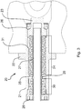
- each elastic member 20 comprises a cylindrical body 21 whose outside is engaged in an orifice of the protrusion 8 to the stop of a flange 22 protruding from the body 21.
- the fastening means of the resilient member 20 to the protrusion are not shown here.
- Each resilient member 20 comprises a pusher 23 slidably mounted in the body 21 while protruding from one end thereof to come into contact with the sleeve 12 of the fuse pin 11.
- a first series of Belleville washers 24, defining a first stiffness, takes on the one hand support on a bearing surface of a diaphragm 25 extending inside the body 21, and acts on the pusher 23 to push it towards the fuse pin 11 being here stopped by a first stop nut 26 screwed into a first end of the body 21.
- the pusher 23 can be driven into the body 21 against the force generated by the first series of washers 24 to abut on the end of an inner tube 27 which passes through the diaphragm 25 so that an opposite end of the tube 27 comes to slide in a second lock nut 28 screwed into a second end of the body 21.
- the tube 27 has a flange 29 which is pushed against the diaphragm 25 by a second series of Belleville washers 30 bearing on the second stop nut 28.
- the pusher 23 When the pusher 23 is pushed back by the fuse pin 11, the pusher 23 travels a first stroke in which it is subjected to the action of the first series of washers 24 which imposes a first stiffness.
- the first race ends when the pusher 23 accosts the tube 27.
- the pusher 23 travels a second race during which it pushes the tube 27 and is therefore subjected to the action of the second series of washers 30 which works in parallel with the first series of washers 24 and thus adding its stiffness to the stiffness of the first series of washers, so that the stiffness seen by the pusher in this second race is greater than the first stiffness.
- This second race ends when the pusher abuts against an internal shoulder 31 of the body 21.
- the operation of the set is as follows. At rest, the pushers 23 of the two resilient members 20 support on either side of the sleeve 12 of the fuse pin 11 to center it in the middle of the oblong orifice. The pushers 23 are slightly detached from the nut 26.
- the wheel 2 is locked in rotation (for example using the brake that equips the wheel), and the winding 4 of the motor is supplied which imposes a torque on the rotor 5 tending to rotate it. If the rotor 5 is not blocked (for example by seizing the motor bearings), it causes the fuse pin 11 to move in the oblong hole 10 so as to push back the pusher 23 of one of the elastic members 20 against its first series of washers 24.
- the motor supply current is sufficient to push one of the pushers against the force developed by the first series of washers 24, but is not sufficient to push the pusher against the force exerted by the second set of washers.
- one of the pushers 23 is pushed back to travel the first race, and engage in the second race, which quickly increase the training effort, without giving rise to a shock detrimental to the holding of the various elements solicited.
- the second series of washers serves as a filter and protection against shocks to the rise in torque.
- the fusible pin 11 is dimensioned to withstand fatigue at current torques encountered in the normal use of the aircraft, but to yield in shear if the transmitted torque was to exceed a given threshold, typically three to five times the fatigue dimensioning torque, in order to protect the motor and avoid any effort on the wheel tending to block it unwanted.
- the invention is not limited to what has just been described, but on the contrary covers any variant entering within the scope defined by the claims.
- the elastic members may be mounted either on the element to be driven as described here, or on the output member of the engine.
- the elastic means presented here are a series of Belleville washers, it will be possible to use other elastic means, such as coil springs. It may be added a damping means.
Landscapes
- Engineering & Computer Science (AREA)
- General Engineering & Computer Science (AREA)
- Mechanical Engineering (AREA)
- Power Engineering (AREA)
- Physics & Mathematics (AREA)
- General Physics & Mathematics (AREA)
- Connection Of Motors, Electrical Generators, Mechanical Devices, And The Like (AREA)
Abstract
Description
- L'invention concerne un procédé pour relier le rotor d'un moteur électrique à un élément à entraîner, permettant une protection contre les couples importants, et permettant de vérifier le bon fonctionnement du moteur.
- Dans le domaine de l'aviation, il est proposé de motoriser les roues des aéronefs à l'aide de moteurs électriques pour permettre le déplacement de l'aéronef au sol sans utiliser ses groupes propulseurs. Cependant, lors de l'atterrissage, les roues sont brutalement mises en rotation, ce qui impose de protéger l'organe de sortie du moteur pour éviter tout endommagement, l'organe de sortie pouvant être le rotor du moteur si celui-ci est en prise directe, ou la sortie d'un réducteur interposé entre le rotor et la roue.
- Il a été proposé d'interposer un embrayage à disques ou un crabot pour désolidariser sélectivement l'organe de sortie de la roue lors de l'atterrissage, et ne le solidariser à la roue que lorsque la vitesse de l'aéronef descend sous un seuil déterminé.
- La désolidarisation permet de mettre en oeuvre différents types de test. En effet, quand la roue est désolidarisée du moteur, on peut alimenter le moteur pour vérifier s'il tourne bien, avec un courant d'alimentation restant sous un seuil déterminé pour une vitesse de rotation donnée. Ce test peut se faire au sol, ou préalablement à l'atterrissage. En outre, Il est possible, préalablement à l'atterrissage, de tester le couple résistant de la roue en la solidarisant à l'organe de sortie et en la faisant tourner, permettant de déceler un problème dans les roulements de la roue. Mais le poids de ces solutions est souvent rédhibitoire. Par ailleurs, ces dispositifs induisent des risques de panne à prendre en compte dans la conception de l'aéronef, ainsi que des opérations de maintenance (graissage, inspection, remplacement des éléments d'usure...).
- Il a également été proposé d'utiliser des broches s'étendant entre l'organe de sortie et l'élément à entraîner, par exemple dans un montage de type à double chape, et calibrées pour céder en cisaillement lorsque le couple transmis par les broches dépasse un seuil déterminé (broches dites fusibles). Cette liaison est beaucoup plus simple et ne nécessite aucune maintenance, sauf le remplacement périodique des broches. Cependant, le moteur est en permanence solidarisé à la roue, empêchant tout test du moteur indépendamment de la roue. En effet, si, préalablement à l'atterrissage, on alimente le moteur et on détecte une résistance anormale, il est impossible de déterminer si la résistance vient du moteur ou de la roue.
- L'invention a pour objet un procédé de liaison par broches fusibles entre l'organe de sortie d'un moteur et un élément à entraîner en rotation, permettant néanmoins de tester le moteur indépendamment l'élément à entraîner.
- En vue de la réalisation de ce but, on propose un procédé pour relier en rotation un organe de sortie d'un moteur électrique avec un élément à entraîner en rotation, comprenant l'utilisation d'au moins une broche fusible qui lie l'organe de sortie et l'élément à entraîner et qui présente au moins une section susceptible de céder en cisaillement quand un couple transmis par la broche fusible dépasse un seuil prédéterminé. Selon l'invention, le procédé comporte l'étape d'interposer, entre la broche et l'un de l'organe de sortie ou de l'élément à entraîner, au moins un organe élastique comportant une première course avec une première raideur, suivie d'une deuxième course avec une deuxième raideur plus forte que la première raideur.
- Ainsi, pour tester le bon fonctionnement du moteur, il suffit de bloquer l'élément à entraîner, et d'alimenter le moteur. Celui-ci doit normalement entraîner la broche à l'encontre de la première raideur de l'organe élastique. En surveillant le courant d'alimentation du moteur, il est possible de vérifier que le couple résistant du moteur reste sous un seuil déterminé, incluant la résistance opposée par l'organe élastique. Puis, une fois ce test effectué, l'élément à entraîner est libéré, et le moteur est de nouveau alimenté. En surveillant le courant d'alimentation du moteur, il est possible de vérifier que le couple résistant de l'ensemble tournant reste sous un seuil prédéterminé. Enfin, en fonctionnement, la deuxième course, avec la raideur plus forte, permet une montée progressive du couple de transmission après que l'organe élastique ait consommé la première course, en évitant tout accostage brutal.
- Selon une caractéristique avantageuse de l'invention, la broche a ses deux extrémités engagées dans l'un de l'organe de sortie ou de l'élément à entraîner, et une partie centrale s'étendant dans l'autre de l'organe de sortie ou de l'élément à entraîner, l'organe élastique étant monté pour agir sur la partie centrale de la broche.
- L'invention sera mieux comprise à la lumière de la description d'un mode particulier de mise en oeuvre du procédé de l'invention, en référence aux figures des dessins annexés, parmi lesquelles :
- La
figure 1 est une vue en coupe schématique d'un moteur dont le rotor est accouplé à un élément à entraîner par une broche fusible ; - La
figure 2 est vue en coupe selon la ligne II-II de lafigure 1 ; - La
figure 3 est une vue en coupe longitudinale de l'un des tampons élastiques interposés entre la broche et l'élément à entraîner. - L'invention s'applique à la liaison entre un moteur 1 et un élément à entraîner en rotation, par exemple ici une roue 2 d'aéronef dont on voit ici l'extrémité du moyeu et montée pour tourner sur une essieu 100 autour d'un axe de rotation X. Le moteur 1 est ici monté coaxialement à la roue 2 et comporte un stator 3 (fixé par exemple à l'essieu de la roue) recevant un bobinage 4. Le moteur comporte par ailleurs un rotor 5 monté tournant autour du stator 3 et comportant des aimants permanents 6 pour interagir électromagnétiquement avec le bobinage 4 du stator 3. A l'extrémité du moyeu de la roue 2 est fixé un flasque 7 dont la périphérie est munie d'une excroissance 8 qui est reçue dans une gorge 9 du rotor 5. L'excroissance est percée d'un orifice 10 de section oblongue dans laquelle s'étend une broche fusible 11, ici recouverte d'un manchon 12 sur sa partie centrale et dont les extrémités sont reçues dans des orifices ajustés ménagés dans des flancs 13 du rotor qui délimitent la gorge 9. L'excroissance 8 porte par ailleurs deux organes élastiques 20 qui sont fixés de part et d'autre de l'excroissance pour saillir dans l'orifice 10 et coopérer avec la broche fusible 11.
- Comme cela est plus particulièrement visible à la
figure 3 , chaque organe élastique 20 comporte un corps cylindrique 21 dont l'extérieur est engagé dans un orifice de l'excroissance 8 jusqu'à butée d'une collerette 22 saillant du corps 21. Les moyens de fixation de l'organe élastique 20 à l'excroissance ne sont pas ici représentés. Chaque organe élastique 20 comporte un poussoir 23 monté coulissant dans le corps 21 tout en saillant d'une extrémité de celui-ci pour venir au contact de du manchon 12 de la broche fusible 11. Une première série de rondelles Belleville 24, définissant une première raideur, prend d'une part appui sur une face d'appui d'un diaphragme 25 s'étendant à l'intérieur du corps 21, et agit sur le poussoir 23 pour le pousser vers la broche fusible 11 en étant ici arrêté par un premier écrou d'arrêt 26 vissé dans une première extrémité du corps 21. Le poussoir 23 peut être enfoncé dans le corps 21 à l'encontre de l'effort généré par la première série de rondelles 24 jusqu'à buter sur l'extrémité d'un tube interne 27 qui passe au travers du diaphragme 25 de sorte qu'une extrémité opposée du tube 27 vienne coulisser dans un deuxième écrou d'arrêt 28 vissé dans une deuxième extrémité du corps 21. Le tube 27 comporte une collerette 29 qui est poussé contre le diaphragme 25 par une deuxième série de rondelles Belleville 30 prenant appui sur le deuxième écrou d'arrêt 28. - Lorsque le poussoir 23 est repoussé par la broche fusible 11, le poussoir 23 parcourt une première course lors de laquelle il est soumis à l'action de la première série de rondelles 24 qui impose une première raideur. La première course se termine quand le poussoir 23 accoste le tube 27. Puis le poussoir 23 parcourt une deuxième course lors de laquelle il repousse le tube 27 et est donc soumis à l'action de la deuxième série de rondelles 30 qui travaille en parallèle de la première série de rondelles 24 et qui ajoute donc sa raideur à la raideur de la première série de rondelles, de sorte que la raideur vue par le poussoir lors de cette deuxième course est supérieure à la première raideur. Cette deuxième course se termine quand le poussoir vient en butée contre un épaulement interne 31 du corps 21.
- Le fonctionnement de l'ensemble est le suivant. Au repos, les poussoirs 23 des deux organes élastiques 20 appuient de part et d'autre du manchon 12 de la broche fusible 11 pour centrer celle-ci au milieu de l'orifice oblong. Les poussoirs 23 sont donc légèrement décollés de l'écrou 26.
- Lors d'un test de bon fonctionnement du moteur 1, par exemple avant un atterrissage, on bloque la roue 2 en rotation (par exemple à l'aide du frein qui équipe la roue), et on alimente le bobinage 4 du moteur ce qui impose un couple sur le rotor 5 tendant à le faire tourner. Si le rotor 5 n'est pas bloqué (par exemple par un grippage des roulements du moteur) il provoque le déplacement de la broche fusible 11 dans l'orifice oblong 10 de sorte à repousser le poussoir 23 de l'un des organes élastiques 20 à l'encontre de sa première série de rondelles 24. Le courant d'alimentation du moteur suffit pour repousser l'un des poussoirs à l'encontre de l'effort développé par la première série de rondelles 24, mais n'est pas suffisante pour repousser le poussoir à l'encontre de l'effort exercé par la deuxième série de rondelles. Il est donc possible de détecter si le courant d'alimentation reste sous un seuil prédéterminé pour une course angulaire du rotor qui correspond à la première course de l'organe élastique sollicité. Si ce n'est pas le cas, c'est que quelque chose gêne la rotation du rotor, et une alerte de d'inspection est alors générée.
- Puis on continue le test en libérant la roue, et en réalimentant le moteur 1 pour vérifier si la roue tourne librement. De la même façon, on détecte si le courant d'alimentation reste sous un seuil prédéterminé. Sous cette charge, les poussoirs ne sont pas repoussés, et la transmission de couple entre le rotor 5 et la roue 2 se fait sans que les organes élastique ne soient compressés.
- En service, lors d'une transmission de couple entre le rotor et la roue 2, par exemple lors de la mise en rotation de la roue à l'atterrissage, ou lorsque le moteur est alimenté pour faire tourner la roue et déplacer l'aéronef au sol, l'un des poussoirs 23 est repoussé pour parcourir la première course, et s'engager dans la deuxième course, ce qui fait rapidement monter l'effort d'entraînement, sans toutefois donner lieu à un choc préjudiciable à la tenue des divers éléments sollicités. La deuxième série de rondelles sert ainsi de filtre et de protection contre les chocs à la montée en couple.
- De préférence, la broche fusible 11 est dimensionnée pour résister en fatigue à des couples courants rencontrés dans l'utilisation normale de l'aéronef, mais pour céder en cisaillement si le couple transmis venait à dépasser un seuil donné, typiquement trois à cinq fois le couple de dimensionnement en fatigue, ceci afin de protéger le moteur et éviter tout effort sur la roue tendant à bloquer celle-ci de façon non désirée.
- L'invention n'est pas limitée à ce qui vient d'être décrit, mais englobe au contraire toute variante entrant dans le cadre défini par les revendications. En particulier, on pourra prévoir plusieurs broches fusibles pour relier l'organe de sortie du moteur à l'élément à entraîner en rotation, chaque broche étant associée à au moins un organe élastique, un seul étant suffisant si le couple transmis est toujours de même sens. Les organes élastiques pourront être montés soit sur l'élément à entraîner comme décrit ici, soit sur l'organe de sortie du moteur.
- Bien que les moyens élastiques présentés ici soient des séries de rondelles Belleville, on pourra utiliser d'autres moyens élastiques, comme des ressorts hélicoïdaux. On pourra y adjoindre un moyen d'amortissement.
Claims (6)
- Procédé pour relier en rotation un organe de sortie (5) d'un moteur électrique (1) avec un élément (2) à entraîner en rotation, comprenant l'utilisation d'au moins une broche fusible (11) qui lie l'organe de sortie et l'élément à entraîner et qui présente au moins une section susceptible de céder en cisaillement quand un couple transmis par la broche fusible dépasse un seuil prédéterminé, caractérisé en ce que le procédé comporte l'étape d'interposer, entre la broche et l'un de l'organe de sortie ou de l'élément à entraîner, au moins un organe élastique (20) comportant une première course avec une première raideur, suivie d'une deuxième course avec une deuxième raideur plus forte que la première raideur.
- Procédé selon la revendication 1, dans lequel la broche a ses deux extrémités engagées dans l'un de l'organe de sortie ou de l'élément à entraîner, et une partie centrale s'étendant dans l'autre de l'organe de sortie ou de l'élément à entraîner, l'organe élastique étant monté pour agir sur la partie centrale de la broche.
- Procédé selon la revendication 1, dans lequel l'organe élastique (20) comporte un corps (21) dans lequel un poussoir est monté pour coulisser et saillir du corps pour coopérer avec la broche fusible (11), le poussoir pouvant être repoussé par la broche fusible à l'encontre d'un premier moyen élastique (24) puis après la première course, à l'encontre d'une deuxième moyen élastique (30) agissant en parallèle avec le premier moyen élastique.
- Procédé selon la revendication 3, dans lequel le premier moyen élastique (24) est disposé entre le corps et le poussoir pour repousser celui-ci, tandis que le deuxième moyen élastique (30) est disposé entre le corps et un tube interne (27) sur lequel le poussoir vient buter à la fin de la première course.
- Procédé de test de bon fonctionnement du moteur électrique relié à un élément à entraîner selon le procédé de liaison conforme à l'une quelconque des revendications précédentes, comprenant l'étape de bloquer en rotation l'élément à entraîner, d'alimenter le moteur avec un courant d'alimentation, et de vérifier si, pour une course angulaire du moteur correspondant à la première course de l'organe élastique, le courant d'alimentation ne dépasse pas un seuil prédéterminé.
- Procédé de test de bon fonctionnement de l'élément à entraîner relié à l'organe de sortie d'un moteur selon le procédé de liaison conforme à l'une des revendications 1 à 4, comportant l'étape, après avoir fait le test de la revendication 5, d'alimenter le moteur avec un courant d'alimentation, et de vérifier si le courant d'alimentation ne dépasse pas un seuil prédéterminé.
Applications Claiming Priority (1)
| Application Number | Priority Date | Filing Date | Title |
|---|---|---|---|
| FR1657967A FR3055487B1 (fr) | 2016-08-26 | 2016-08-26 | Liaison entre un rotor de moteur electrique et un element a entrainer |
Publications (2)
| Publication Number | Publication Date |
|---|---|
| EP3297136A1 true EP3297136A1 (fr) | 2018-03-21 |
| EP3297136B1 EP3297136B1 (fr) | 2019-02-27 |
Family
ID=57860946
Family Applications (1)
| Application Number | Title | Priority Date | Filing Date |
|---|---|---|---|
| EP17186971.2A Active EP3297136B1 (fr) | 2016-08-26 | 2017-08-18 | Liaison entre un rotor de moteur électrique et un élément à entrainer |
Country Status (4)
| Country | Link |
|---|---|
| US (1) | US10288127B2 (fr) |
| EP (1) | EP3297136B1 (fr) |
| CN (1) | CN107786035B (fr) |
| FR (1) | FR3055487B1 (fr) |
Families Citing this family (2)
| Publication number | Priority date | Publication date | Assignee | Title |
|---|---|---|---|---|
| US11332236B2 (en) | 2017-05-27 | 2022-05-17 | Borealis Technical Limited | Force limiting system and method for limiting loads in a powered aircraft landing gear drive wheel |
| GB2574446B (en) * | 2018-06-06 | 2020-10-28 | Borealis Tech Ltd | System and method for limiting loads produced by an aircraft landing gear wheel taxi drive system |
Citations (2)
| Publication number | Priority date | Publication date | Assignee | Title |
|---|---|---|---|---|
| DE2538975A1 (de) * | 1975-08-29 | 1977-03-10 | Siemens Ag | Sicherheitskupplung |
| JP2008256068A (ja) * | 2007-04-04 | 2008-10-23 | Sanden Corp | トルク伝達装置 |
Family Cites Families (5)
| Publication number | Priority date | Publication date | Assignee | Title |
|---|---|---|---|---|
| US6822825B2 (en) * | 2000-12-04 | 2004-11-23 | Seagate Technology Llc | Stiffness compensation for a thermally compensated fluid dynamic bearing |
| KR101033572B1 (ko) * | 2004-02-26 | 2011-05-11 | 엘지전자 주식회사 | 드럼세탁기용 아웃터로터형 모터의 스테이터 구조 |
| CN202108895U (zh) * | 2011-05-28 | 2012-01-11 | 天华化工机械及自动化研究设计院 | 一种安全销弹性联轴器 |
| CN202201612U (zh) * | 2011-07-21 | 2012-04-25 | 苏州通润驱动设备股份有限公司 | 自动扶梯驱动主机 |
| CN104235217A (zh) * | 2014-09-15 | 2014-12-24 | 镇江索达联轴器有限公司 | 一种电机用联轴器 |
-
2016
- 2016-08-26 FR FR1657967A patent/FR3055487B1/fr not_active Expired - Fee Related
-
2017
- 2017-08-18 EP EP17186971.2A patent/EP3297136B1/fr active Active
- 2017-08-24 US US15/685,195 patent/US10288127B2/en active Active
- 2017-08-25 CN CN201710742423.4A patent/CN107786035B/zh active Active
Patent Citations (2)
| Publication number | Priority date | Publication date | Assignee | Title |
|---|---|---|---|---|
| DE2538975A1 (de) * | 1975-08-29 | 1977-03-10 | Siemens Ag | Sicherheitskupplung |
| JP2008256068A (ja) * | 2007-04-04 | 2008-10-23 | Sanden Corp | トルク伝達装置 |
Also Published As
| Publication number | Publication date |
|---|---|
| US10288127B2 (en) | 2019-05-14 |
| CN107786035B (zh) | 2019-12-06 |
| CN107786035A (zh) | 2018-03-09 |
| FR3055487B1 (fr) | 2018-08-10 |
| EP3297136B1 (fr) | 2019-02-27 |
| US20180058510A1 (en) | 2018-03-01 |
| FR3055487A1 (fr) | 2018-03-02 |
Similar Documents
| Publication | Publication Date | Title |
|---|---|---|
| EP3287652B1 (fr) | Roue d'aeronef a boitier a roulements separable | |
| EP2948402B1 (fr) | Machine d'entrainement d'un ascenseur | |
| EP1845016A1 (fr) | Atterrisseur comportant plusieurs actionneurs électromécaniques d'orientation | |
| EP2361830A1 (fr) | Ensemble de roue et frein pour aéronef équipé d'un dispositif d'entraînement en rotation | |
| EP0199642A1 (fr) | Embrayage à commande par moteur, notamment pour véhicule automobile | |
| FR2939763A1 (fr) | Train d'atterrissage motorise pour aeronef | |
| EP3297136B1 (fr) | Liaison entre un rotor de moteur électrique et un élément à entrainer | |
| WO2016005134A2 (fr) | Actionneur electromecanique a limiteur de couple mecanique a rouleaux | |
| FR2930805A1 (fr) | Procede et organe de serrage d'un element de visserie, dispositif de fixation et de serrage | |
| FR3116578A1 (fr) | Dispositif d’entraînement électrique d’un essieu d’un véhicule | |
| FR2887945A1 (fr) | Manchon decoupleur | |
| FR2516187A1 (fr) | Perfectionnement des accouplements elastiques et procede perfectionne d'entrainement de deux arbres | |
| EP4082916A1 (fr) | Aeronef equipe d'un systeme de transmission | |
| EP2000693B1 (fr) | Ensemble de roue et frein pour aéronef | |
| EP2003384A1 (fr) | Système de raccordement comprenant des moyens de fixation de sécurité | |
| EP0239457B1 (fr) | Volant amortisseur pour transmission, notamment pour véhicule automobile | |
| FR2979039A1 (fr) | Machine electrique et son procede de montage | |
| WO2007036633A1 (fr) | Module de securite pour transmission et assemblage correspondant | |
| FR3130469A1 (fr) | Dispositif de déconnexion d’un générateur entrainé par un rotor, ensemble générateur-moteur associés. | |
| EP3401200B1 (fr) | Dispositif de fixation d'une roue de cycle | |
| EP3740685B1 (fr) | Ventilateur pour un groupe de refroidissement d'aeronef | |
| FR2731197A1 (fr) | Dispositif d'accouplement elastique entre deux arbres d'un ensemble de direction pour vehicule automobile | |
| FR3032019A1 (fr) | Amortisseur de torsion a ressorts droits | |
| FR3132602A1 (fr) | Dispositif de déconnexion et de freinage d’un rotor d’une machine électrique | |
| FR3163132A1 (fr) | Roue freinée avec bagues d’atténuation de vibration, atterrisseur et aéronef comportant une telle roue |
Legal Events
| Date | Code | Title | Description |
|---|---|---|---|
| PUAI | Public reference made under article 153(3) epc to a published international application that has entered the european phase |
Free format text: ORIGINAL CODE: 0009012 |
|
| STAA | Information on the status of an ep patent application or granted ep patent |
Free format text: STATUS: THE APPLICATION HAS BEEN PUBLISHED |
|
| AK | Designated contracting states |
Kind code of ref document: A1 Designated state(s): AL AT BE BG CH CY CZ DE DK EE ES FI FR GB GR HR HU IE IS IT LI LT LU LV MC MK MT NL NO PL PT RO RS SE SI SK SM TR |
|
| AX | Request for extension of the european patent |
Extension state: BA ME |
|
| STAA | Information on the status of an ep patent application or granted ep patent |
Free format text: STATUS: REQUEST FOR EXAMINATION WAS MADE |
|
| 17P | Request for examination filed |
Effective date: 20180330 |
|
| RBV | Designated contracting states (corrected) |
Designated state(s): AL AT BE BG CH CY CZ DE DK EE ES FI FR GB GR HR HU IE IS IT LI LT LU LV MC MK MT NL NO PL PT RO RS SE SI SK SM TR |
|
| GRAP | Despatch of communication of intention to grant a patent |
Free format text: ORIGINAL CODE: EPIDOSNIGR1 |
|
| STAA | Information on the status of an ep patent application or granted ep patent |
Free format text: STATUS: GRANT OF PATENT IS INTENDED |
|
| RIC1 | Information provided on ipc code assigned before grant |
Ipc: H02K 7/00 20060101ALI20180921BHEP Ipc: H02K 7/14 20060101AFI20180921BHEP Ipc: F16D 9/06 20060101ALI20180921BHEP Ipc: F16D 3/72 20060101ALI20180921BHEP |
|
| INTG | Intention to grant announced |
Effective date: 20181019 |
|
| GRAS | Grant fee paid |
Free format text: ORIGINAL CODE: EPIDOSNIGR3 |
|
| GRAA | (expected) grant |
Free format text: ORIGINAL CODE: 0009210 |
|
| STAA | Information on the status of an ep patent application or granted ep patent |
Free format text: STATUS: THE PATENT HAS BEEN GRANTED |
|
| AK | Designated contracting states |
Kind code of ref document: B1 Designated state(s): AL AT BE BG CH CY CZ DE DK EE ES FI FR GB GR HR HU IE IS IT LI LT LU LV MC MK MT NL NO PL PT RO RS SE SI SK SM TR |
|
| REG | Reference to a national code |
Ref country code: GB Ref legal event code: FG4D Free format text: NOT ENGLISH |
|
| REG | Reference to a national code |
Ref country code: CH Ref legal event code: EP |
|
| REG | Reference to a national code |
Ref country code: AT Ref legal event code: REF Ref document number: 1102748 Country of ref document: AT Kind code of ref document: T Effective date: 20190315 |
|
| REG | Reference to a national code |
Ref country code: IE Ref legal event code: FG4D Free format text: LANGUAGE OF EP DOCUMENT: FRENCH |
|
| REG | Reference to a national code |
Ref country code: DE Ref legal event code: R096 Ref document number: 602017002351 Country of ref document: DE |
|
| REG | Reference to a national code |
Ref country code: NL Ref legal event code: MP Effective date: 20190227 |
|
| REG | Reference to a national code |
Ref country code: LT Ref legal event code: MG4D |
|
| PG25 | Lapsed in a contracting state [announced via postgrant information from national office to epo] |
Ref country code: LT Free format text: LAPSE BECAUSE OF FAILURE TO SUBMIT A TRANSLATION OF THE DESCRIPTION OR TO PAY THE FEE WITHIN THE PRESCRIBED TIME-LIMIT Effective date: 20190227 Ref country code: NL Free format text: LAPSE BECAUSE OF FAILURE TO SUBMIT A TRANSLATION OF THE DESCRIPTION OR TO PAY THE FEE WITHIN THE PRESCRIBED TIME-LIMIT Effective date: 20190227 Ref country code: SE Free format text: LAPSE BECAUSE OF FAILURE TO SUBMIT A TRANSLATION OF THE DESCRIPTION OR TO PAY THE FEE WITHIN THE PRESCRIBED TIME-LIMIT Effective date: 20190227 Ref country code: NO Free format text: LAPSE BECAUSE OF FAILURE TO SUBMIT A TRANSLATION OF THE DESCRIPTION OR TO PAY THE FEE WITHIN THE PRESCRIBED TIME-LIMIT Effective date: 20190527 Ref country code: PT Free format text: LAPSE BECAUSE OF FAILURE TO SUBMIT A TRANSLATION OF THE DESCRIPTION OR TO PAY THE FEE WITHIN THE PRESCRIBED TIME-LIMIT Effective date: 20190627 Ref country code: FI Free format text: LAPSE BECAUSE OF FAILURE TO SUBMIT A TRANSLATION OF THE DESCRIPTION OR TO PAY THE FEE WITHIN THE PRESCRIBED TIME-LIMIT Effective date: 20190227 |
|
| PG25 | Lapsed in a contracting state [announced via postgrant information from national office to epo] |
Ref country code: IS Free format text: LAPSE BECAUSE OF FAILURE TO SUBMIT A TRANSLATION OF THE DESCRIPTION OR TO PAY THE FEE WITHIN THE PRESCRIBED TIME-LIMIT Effective date: 20190627 Ref country code: LV Free format text: LAPSE BECAUSE OF FAILURE TO SUBMIT A TRANSLATION OF THE DESCRIPTION OR TO PAY THE FEE WITHIN THE PRESCRIBED TIME-LIMIT Effective date: 20190227 Ref country code: HR Free format text: LAPSE BECAUSE OF FAILURE TO SUBMIT A TRANSLATION OF THE DESCRIPTION OR TO PAY THE FEE WITHIN THE PRESCRIBED TIME-LIMIT Effective date: 20190227 Ref country code: GR Free format text: LAPSE BECAUSE OF FAILURE TO SUBMIT A TRANSLATION OF THE DESCRIPTION OR TO PAY THE FEE WITHIN THE PRESCRIBED TIME-LIMIT Effective date: 20190528 Ref country code: RS Free format text: LAPSE BECAUSE OF FAILURE TO SUBMIT A TRANSLATION OF THE DESCRIPTION OR TO PAY THE FEE WITHIN THE PRESCRIBED TIME-LIMIT Effective date: 20190227 Ref country code: BG Free format text: LAPSE BECAUSE OF FAILURE TO SUBMIT A TRANSLATION OF THE DESCRIPTION OR TO PAY THE FEE WITHIN THE PRESCRIBED TIME-LIMIT Effective date: 20190527 |
|
| REG | Reference to a national code |
Ref country code: AT Ref legal event code: MK05 Ref document number: 1102748 Country of ref document: AT Kind code of ref document: T Effective date: 20190227 |
|
| PG25 | Lapsed in a contracting state [announced via postgrant information from national office to epo] |
Ref country code: ES Free format text: LAPSE BECAUSE OF FAILURE TO SUBMIT A TRANSLATION OF THE DESCRIPTION OR TO PAY THE FEE WITHIN THE PRESCRIBED TIME-LIMIT Effective date: 20190227 Ref country code: DK Free format text: LAPSE BECAUSE OF FAILURE TO SUBMIT A TRANSLATION OF THE DESCRIPTION OR TO PAY THE FEE WITHIN THE PRESCRIBED TIME-LIMIT Effective date: 20190227 Ref country code: CZ Free format text: LAPSE BECAUSE OF FAILURE TO SUBMIT A TRANSLATION OF THE DESCRIPTION OR TO PAY THE FEE WITHIN THE PRESCRIBED TIME-LIMIT Effective date: 20190227 Ref country code: EE Free format text: LAPSE BECAUSE OF FAILURE TO SUBMIT A TRANSLATION OF THE DESCRIPTION OR TO PAY THE FEE WITHIN THE PRESCRIBED TIME-LIMIT Effective date: 20190227 Ref country code: RO Free format text: LAPSE BECAUSE OF FAILURE TO SUBMIT A TRANSLATION OF THE DESCRIPTION OR TO PAY THE FEE WITHIN THE PRESCRIBED TIME-LIMIT Effective date: 20190227 Ref country code: IT Free format text: LAPSE BECAUSE OF FAILURE TO SUBMIT A TRANSLATION OF THE DESCRIPTION OR TO PAY THE FEE WITHIN THE PRESCRIBED TIME-LIMIT Effective date: 20190227 Ref country code: AL Free format text: LAPSE BECAUSE OF FAILURE TO SUBMIT A TRANSLATION OF THE DESCRIPTION OR TO PAY THE FEE WITHIN THE PRESCRIBED TIME-LIMIT Effective date: 20190227 Ref country code: SK Free format text: LAPSE BECAUSE OF FAILURE TO SUBMIT A TRANSLATION OF THE DESCRIPTION OR TO PAY THE FEE WITHIN THE PRESCRIBED TIME-LIMIT Effective date: 20190227 |
|
| REG | Reference to a national code |
Ref country code: DE Ref legal event code: R097 Ref document number: 602017002351 Country of ref document: DE |
|
| PG25 | Lapsed in a contracting state [announced via postgrant information from national office to epo] |
Ref country code: PL Free format text: LAPSE BECAUSE OF FAILURE TO SUBMIT A TRANSLATION OF THE DESCRIPTION OR TO PAY THE FEE WITHIN THE PRESCRIBED TIME-LIMIT Effective date: 20190227 Ref country code: SM Free format text: LAPSE BECAUSE OF FAILURE TO SUBMIT A TRANSLATION OF THE DESCRIPTION OR TO PAY THE FEE WITHIN THE PRESCRIBED TIME-LIMIT Effective date: 20190227 |
|
| PG25 | Lapsed in a contracting state [announced via postgrant information from national office to epo] |
Ref country code: AT Free format text: LAPSE BECAUSE OF FAILURE TO SUBMIT A TRANSLATION OF THE DESCRIPTION OR TO PAY THE FEE WITHIN THE PRESCRIBED TIME-LIMIT Effective date: 20190227 |
|
| PLBE | No opposition filed within time limit |
Free format text: ORIGINAL CODE: 0009261 |
|
| STAA | Information on the status of an ep patent application or granted ep patent |
Free format text: STATUS: NO OPPOSITION FILED WITHIN TIME LIMIT |
|
| 26N | No opposition filed |
Effective date: 20191128 |
|
| PG25 | Lapsed in a contracting state [announced via postgrant information from national office to epo] |
Ref country code: SI Free format text: LAPSE BECAUSE OF FAILURE TO SUBMIT A TRANSLATION OF THE DESCRIPTION OR TO PAY THE FEE WITHIN THE PRESCRIBED TIME-LIMIT Effective date: 20190227 |
|
| PG25 | Lapsed in a contracting state [announced via postgrant information from national office to epo] |
Ref country code: TR Free format text: LAPSE BECAUSE OF FAILURE TO SUBMIT A TRANSLATION OF THE DESCRIPTION OR TO PAY THE FEE WITHIN THE PRESCRIBED TIME-LIMIT Effective date: 20190227 |
|
| PG25 | Lapsed in a contracting state [announced via postgrant information from national office to epo] |
Ref country code: MC Free format text: LAPSE BECAUSE OF FAILURE TO SUBMIT A TRANSLATION OF THE DESCRIPTION OR TO PAY THE FEE WITHIN THE PRESCRIBED TIME-LIMIT Effective date: 20190227 Ref country code: LU Free format text: LAPSE BECAUSE OF NON-PAYMENT OF DUE FEES Effective date: 20190818 |
|
| REG | Reference to a national code |
Ref country code: BE Ref legal event code: MM Effective date: 20190831 |
|
| PG25 | Lapsed in a contracting state [announced via postgrant information from national office to epo] |
Ref country code: IE Free format text: LAPSE BECAUSE OF NON-PAYMENT OF DUE FEES Effective date: 20190818 |
|
| PG25 | Lapsed in a contracting state [announced via postgrant information from national office to epo] |
Ref country code: BE Free format text: LAPSE BECAUSE OF NON-PAYMENT OF DUE FEES Effective date: 20190831 |
|
| REG | Reference to a national code |
Ref country code: CH Ref legal event code: PL |
|
| PG25 | Lapsed in a contracting state [announced via postgrant information from national office to epo] |
Ref country code: CH Free format text: LAPSE BECAUSE OF NON-PAYMENT OF DUE FEES Effective date: 20200831 Ref country code: LI Free format text: LAPSE BECAUSE OF NON-PAYMENT OF DUE FEES Effective date: 20200831 |
|
| PG25 | Lapsed in a contracting state [announced via postgrant information from national office to epo] |
Ref country code: CY Free format text: LAPSE BECAUSE OF FAILURE TO SUBMIT A TRANSLATION OF THE DESCRIPTION OR TO PAY THE FEE WITHIN THE PRESCRIBED TIME-LIMIT Effective date: 20190227 |
|
| PG25 | Lapsed in a contracting state [announced via postgrant information from national office to epo] |
Ref country code: HU Free format text: LAPSE BECAUSE OF FAILURE TO SUBMIT A TRANSLATION OF THE DESCRIPTION OR TO PAY THE FEE WITHIN THE PRESCRIBED TIME-LIMIT; INVALID AB INITIO Effective date: 20170818 Ref country code: MT Free format text: LAPSE BECAUSE OF FAILURE TO SUBMIT A TRANSLATION OF THE DESCRIPTION OR TO PAY THE FEE WITHIN THE PRESCRIBED TIME-LIMIT Effective date: 20190227 |
|
| PG25 | Lapsed in a contracting state [announced via postgrant information from national office to epo] |
Ref country code: MK Free format text: LAPSE BECAUSE OF FAILURE TO SUBMIT A TRANSLATION OF THE DESCRIPTION OR TO PAY THE FEE WITHIN THE PRESCRIBED TIME-LIMIT Effective date: 20190227 |
|
| PGFP | Annual fee paid to national office [announced via postgrant information from national office to epo] |
Ref country code: DE Payment date: 20250819 Year of fee payment: 9 |
|
| PGFP | Annual fee paid to national office [announced via postgrant information from national office to epo] |
Ref country code: GB Payment date: 20250825 Year of fee payment: 9 |
|
| PGFP | Annual fee paid to national office [announced via postgrant information from national office to epo] |
Ref country code: FR Payment date: 20250821 Year of fee payment: 9 |