EP3297089A1 - Flurförderzeug mit einer traktionsbatterie - Google Patents
Flurförderzeug mit einer traktionsbatterie Download PDFInfo
- Publication number
- EP3297089A1 EP3297089A1 EP17188993.4A EP17188993A EP3297089A1 EP 3297089 A1 EP3297089 A1 EP 3297089A1 EP 17188993 A EP17188993 A EP 17188993A EP 3297089 A1 EP3297089 A1 EP 3297089A1
- Authority
- EP
- European Patent Office
- Prior art keywords
- battery
- truck
- air flow
- fan
- cooling
- Prior art date
- Legal status (The legal status is an assumption and is not a legal conclusion. Google has not performed a legal analysis and makes no representation as to the accuracy of the status listed.)
- Granted
Links
Images

Classifications
-
- H—ELECTRICITY
- H01—ELECTRIC ELEMENTS
- H01M—PROCESSES OR MEANS, e.g. BATTERIES, FOR THE DIRECT CONVERSION OF CHEMICAL ENERGY INTO ELECTRICAL ENERGY
- H01M10/00—Secondary cells; Manufacture thereof
- H01M10/60—Heating or cooling; Temperature control
- H01M10/65—Means for temperature control structurally associated with the cells
- H01M10/656—Means for temperature control structurally associated with the cells characterised by the type of heat-exchange fluid
- H01M10/6561—Gases
- H01M10/6563—Gases with forced flow, e.g. by blowers
-
- H—ELECTRICITY
- H01—ELECTRIC ELEMENTS
- H01M—PROCESSES OR MEANS, e.g. BATTERIES, FOR THE DIRECT CONVERSION OF CHEMICAL ENERGY INTO ELECTRICAL ENERGY
- H01M50/00—Constructional details or processes of manufacture of the non-active parts of electrochemical cells other than fuel cells, e.g. hybrid cells
- H01M50/20—Mountings; Secondary casings or frames; Racks, modules or packs; Suspension devices; Shock absorbers; Transport or carrying devices; Holders
- H01M50/249—Mountings; Secondary casings or frames; Racks, modules or packs; Suspension devices; Shock absorbers; Transport or carrying devices; Holders specially adapted for aircraft or vehicles, e.g. cars or trains
-
- B—PERFORMING OPERATIONS; TRANSPORTING
- B60—VEHICLES IN GENERAL
- B60L—PROPULSION OF ELECTRICALLY-PROPELLED VEHICLES; SUPPLYING ELECTRIC POWER FOR AUXILIARY EQUIPMENT OF ELECTRICALLY-PROPELLED VEHICLES; ELECTRODYNAMIC BRAKE SYSTEMS FOR VEHICLES IN GENERAL; MAGNETIC SUSPENSION OR LEVITATION FOR VEHICLES; MONITORING OPERATING VARIABLES OF ELECTRICALLY-PROPELLED VEHICLES; ELECTRIC SAFETY DEVICES FOR ELECTRICALLY-PROPELLED VEHICLES
- B60L50/00—Electric propulsion with power supplied within the vehicle
- B60L50/50—Electric propulsion with power supplied within the vehicle using propulsion power supplied by batteries or fuel cells
- B60L50/60—Electric propulsion with power supplied within the vehicle using propulsion power supplied by batteries or fuel cells using power supplied by batteries
- B60L50/64—Constructional details of batteries specially adapted for electric vehicles
-
- B—PERFORMING OPERATIONS; TRANSPORTING
- B66—HOISTING; LIFTING; HAULING
- B66F—HOISTING, LIFTING, HAULING OR PUSHING, NOT OTHERWISE PROVIDED FOR, e.g. DEVICES WHICH APPLY A LIFTING OR PUSHING FORCE DIRECTLY TO THE SURFACE OF A LOAD
- B66F9/00—Devices for lifting or lowering bulky or heavy goods for loading or unloading purposes
- B66F9/06—Devices for lifting or lowering bulky or heavy goods for loading or unloading purposes movable, with their loads, on wheels or the like, e.g. fork-lift trucks
- B66F9/075—Constructional features or details
- B66F9/07513—Details concerning the chassis
- B66F9/07531—Battery compartments
-
- B—PERFORMING OPERATIONS; TRANSPORTING
- B66—HOISTING; LIFTING; HAULING
- B66F—HOISTING, LIFTING, HAULING OR PUSHING, NOT OTHERWISE PROVIDED FOR, e.g. DEVICES WHICH APPLY A LIFTING OR PUSHING FORCE DIRECTLY TO THE SURFACE OF A LOAD
- B66F9/00—Devices for lifting or lowering bulky or heavy goods for loading or unloading purposes
- B66F9/06—Devices for lifting or lowering bulky or heavy goods for loading or unloading purposes movable, with their loads, on wheels or the like, e.g. fork-lift trucks
- B66F9/075—Constructional features or details
- B66F9/07595—Cooling arrangements for device or operator
-
- H—ELECTRICITY
- H01—ELECTRIC ELEMENTS
- H01M—PROCESSES OR MEANS, e.g. BATTERIES, FOR THE DIRECT CONVERSION OF CHEMICAL ENERGY INTO ELECTRICAL ENERGY
- H01M10/00—Secondary cells; Manufacture thereof
- H01M10/60—Heating or cooling; Temperature control
- H01M10/61—Types of temperature control
- H01M10/613—Cooling or keeping cold
-
- H—ELECTRICITY
- H01—ELECTRIC ELEMENTS
- H01M—PROCESSES OR MEANS, e.g. BATTERIES, FOR THE DIRECT CONVERSION OF CHEMICAL ENERGY INTO ELECTRICAL ENERGY
- H01M10/00—Secondary cells; Manufacture thereof
- H01M10/60—Heating or cooling; Temperature control
- H01M10/62—Heating or cooling; Temperature control specially adapted for specific applications
- H01M10/625—Vehicles
-
- H—ELECTRICITY
- H01—ELECTRIC ELEMENTS
- H01M—PROCESSES OR MEANS, e.g. BATTERIES, FOR THE DIRECT CONVERSION OF CHEMICAL ENERGY INTO ELECTRICAL ENERGY
- H01M2220/00—Batteries for particular applications
- H01M2220/20—Batteries in motive systems, e.g. vehicle, ship, plane
-
- Y—GENERAL TAGGING OF NEW TECHNOLOGICAL DEVELOPMENTS; GENERAL TAGGING OF CROSS-SECTIONAL TECHNOLOGIES SPANNING OVER SEVERAL SECTIONS OF THE IPC; TECHNICAL SUBJECTS COVERED BY FORMER USPC CROSS-REFERENCE ART COLLECTIONS [XRACs] AND DIGESTS
- Y02—TECHNOLOGIES OR APPLICATIONS FOR MITIGATION OR ADAPTATION AGAINST CLIMATE CHANGE
- Y02E—REDUCTION OF GREENHOUSE GAS [GHG] EMISSIONS, RELATED TO ENERGY GENERATION, TRANSMISSION OR DISTRIBUTION
- Y02E60/00—Enabling technologies; Technologies with a potential or indirect contribution to GHG emissions mitigation
- Y02E60/10—Energy storage using batteries
Definitions
- the invention relates to an industrial truck with a traction battery, wherein the traction battery has a plurality of arranged in a battery block battery cells and is arranged in a battery compartment of the truck.
- traction batteries are used, which are usually used as interchangeable batteries in a battery compartment of the truck and, once they are discharged, can be replaced with a charged traction battery.
- these traction batteries are designed as lead-acid batteries, for example as a lead-acid battery or as lead-gel batteries.
- Such traction batteries are constructed so that multiple series-connected, standardized battery cells are arranged in a battery tray.
- the series connection a required voltage is achieved.
- the battery tray protects the built-in battery cells from damage.
- the various possible battery trays and their nominal weights are also standardized.
- the total weight of the traction battery is usually considered in battery-powered counterbalance forklifts as part of an effective counterweight to a load in the stability calculations. For this reason, it is not possible to use smaller or lighter traction batteries.
- traction batteries are designed so that the largest possible cells are used in the battery tray in order to achieve the highest possible energy density and capacity of the traction battery by maximum utilization of the space.
- Lead-acid batteries as traction batteries are very robust and proven for decades in use on industrial trucks.
- a disadvantage of lead-acid batteries as traction batteries is that lead-acid batteries compared to, for example, lithium-ion batteries have a relatively high internal resistance. The high internal resistance leads to a high heat input into the traction battery both during discharging and during charging.
- the present invention has for its object to provide a truck with a traction battery of the type mentioned available in which long cooling phases of the traction battery can be prevented with little construction and the operating time of the traction battery can be increased.
- This object is achieved in that between the battery cells at least one cooling channel is arranged in the battery tray and the truck is provided with a fan, with which a cooling channel through the flowing air flow can be generated, wherein at the cooling channel Air flow inlet, which is connectable to the outlet of the fan, and an airflow outlet is formed.
- the truck is provided with a fan which generates an air flow, which is directed into a cooling channel which is arranged between the battery cells in the battery tray, so that generated by the vehicle-side fan air flow of the space between the battery cells in the battery tray ventilated and thus is cooled.
- a fan which generates an air flow
- the cooling channels in the battery tray and air cooling in which an airflow flowing through the cooling duct can be generated by a fan arranged in the industrial truck, air cooling can thus be achieved with low construction costs for large traction batteries designed as lead-acid batteries, so that long cooling times can be avoided and the service life of the traction battery in the truck can be increased.
- the airflow generated by the vehicle-side fan flows in the cooling channel of the traction battery from the airflow inlet to the airflow outlet.
- the vehicle-side fan makes it possible in this case advantageously to suck in cool air, for example, from an engine compartment of the truck or from the environment of the truck, which is introduced into the cooling channels of the traction battery for the cooling, so that the traction battery can be effectively cooled. Due to the cooling channels and the air cooling in the cooling channels can thus be discharged much better from the interior of the traction battery already during the discharge of the traction battery as well as when charging the traction battery and during breaks the waste heat. This applies in particular to the battery cells, which are arranged inside the battery trough in the middle or in a central region. In contrast to battery cells on the edge of the battery trough, these can deliver little heat via convection to the walls of the battery trough and therefore have a higher temperature.
- the air flow inlet and the air flow outlet are formed on a cover covering the cooling channel.
- the air flow generated by the vehicle-side fan can thus be effectively guided in the cooling passage from the air flow inlet to the air flow outlet, so that an effective dissipation of heat from the traction battery is achieved.
- the cooling channel is provided with an air flow guiding device which controls the air flow generated by the fan in the cooling passage from the air flow inlet to the air flow outlet passes.
- An air flow guide device in the cooling passage makes it possible to guide the air flow generated by the vehicle side fan in a desired manner in the cooling passage from the air flow inlet to the air flow outlet.
- the air flow generated by the fan is guided and guided by the air flow guiding device in the interior of the cooling channel in such a way that the air flow from outer sides of the battery cells dissipates as much heat as possible via the air.
- a simple construction cost for the air cooling of the traction battery can be achieved if, according to an advantageous embodiment of the invention, the air flow inlet and the air flow outlet are formed on the traction battery of cooling hoses.
- the outlet of the fan is formed by a cooling hose. This makes it possible to easily connect and disconnect the exhaust of the vehicle-side fan with the air flow inlet to the traction battery when the traction battery is removed or installed in the event of a change of the traction battery from the battery compartment of the truck.
- the airflow outlet of the cooling channel can be connected to an outlet on the industrial truck. This makes it possible in a simple manner to lead out the heated air from the cooling channel via an outlet on the truck from the battery compartment and thus out of the truck.
- the fan can be operated continuously during operation of the truck.
- the fan is temperature-dependent controlled by a temperature sensor arranged in the truck.
- the fan is turned on and off depending on the performance of the truck. This makes it possible in a simple manner to turn the fan on and off as needed, for example, turn on with higher power of the vehicle and turn off at lower power of the vehicle.
- the fan is part of the electrical system of the truck and is controlled by an electronic vehicle control of the truck.
- the construction cost of the traction battery is reduced because no fan is required on the traction battery for air cooling.
- the traction battery is provided with an additional fan, with which a cooling channel flowing through the air flow can be generated.
- an additional fan with which a cooling channel flowing through the air flow can be generated.
- the additional fan is arranged in the cooling channel. This allows a particularly effective circulation and promotion of the air flow from the additional fan in the cooling channel of that of the air flow inlet to the air flow outlet.
- the traction battery is advantageously designed as a lead-acid battery or as a lead-gel battery.
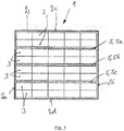
- the traction battery 1 has a battery tray 2, in which a plurality of battery cells 3 are installed.
- the traction battery 1 is designed as a lead-acid battery or as a lead-gel battery.
- the battery cells 3 are dimensioned such that a space which forms at least one cooling channel 5 in the battery tray 2 remains between the battery cells 3.
- three parallel cooling channels 5a, 5b, 5c are provided.
- the cooling channels 5a-5c each extend from one into the FIGS. 1 . 2 left wall 2a to an opposite right wall 2b of the battery trough second
- the cooling channel 5b is preferably arranged centrally between the walls 2c, 2d in the battery tray 2.
- the cooling channels 5a-5c extend preferably from the top of the battery cells 3 to a bottom of the battery trough 2.
- the cooling channels 5a-5c thus forms a rectangular cavity between the battery cells 3, which extends over the full length and depth of the battery trough 2.
- the truck no longer shown has a battery compartment into which the traction battery 1 is inserted.
- the truck is - as in the FIG. 2 is shown - provided with a mounted in the conveyor belt fan 10.
- a space between the battery cells 3 and thus the cooling channel 5 flowing through the air flow 11 is generated.
- the Fan 10 thus ventilates the space between the battery cells 3 and thus the cooling channel 5.
- the vehicle-side fan 10 is preferably designed and arranged such that it sucks in cool air, for example from a unit room of the truck or from the environment outside the truck, and the cool Air in the cooling channel 5 of the traction battery 1 initiates its cooling.
- the cooling channel 5 of the traction battery 1 is provided with an air flow inlet 12.
- the fan 10 has an outlet 13, which is connectable to the air flow inlet 12 of the traction battery 1 at a connection point or separation point 14.
- the cooling channel 5 of the traction battery 1 is further provided with an airflow outlet 15.
- the airflow outlet 15 on the traction battery 5 is connected to an outlet 16 of the industrial truck, on which the heated air can flow out of the battery compartment of the industrial truck 1.
- the air cooling is formed on the central cooling channel 5b.
- the central area inside the battery trough 2 tends to accumulate heat during operation of the traction battery 1. Therefore, it is particularly advantageous to cool this area.
- the cooling channels 5a, 5c may be provided with the air cooling.
- the cooling channel 5 is covered at the top of the battery cells 3 by a cover 20, on which the air flow inlet 12 and the air flow outlet 15 are formed.
- the airflow inlet 12 and the airflow outlet 15 are preferably formed by cooling tubes.
- the outlet 13 of the fan 10 is preferably also formed by a cooling hose.
- an air flow guide device 25 is formed, which directs the air flow generated by the fan 11 in the cooling channel 5 from the air flow inlet 12 to the air flow outlet 15.
- the air flow guiding device 25 generates a meandering air flow within the cooling channel 5 from the air flow inlet 12 to the air flow outlet 15.
- the battery cells 5 are cooled laterally. With the fan 10 in this case the space between the battery cells 3 is vented.
- the arranged in the truck fan 10 is connected to the air duct formed by the outlet 13 and the air flow inlet 12 with the arranged in the battery compartment traction battery 1.
- the outlet 13 is disposed on the fan 10 and the air flow inlet 12 on the traction battery 1. If the outlet 13 and the air flow inlet 12 are each formed by a cooling hose, that part of the air duct formed by cooling hoses is thus mounted on the traction battery 1, which Air duct with the cooling channel 5 connects, and that part of the air duct formed by cooling ducts mounted on the truck, which connects the vehicle-side fan 10 with the traction battery 1.
- the outlet 13 and the airflow inlet 12 may be formed as heatable cooling hoses.
- the air cooling according to the invention makes it possible here with low construction costs to cool with an air flow 11 in the middle of the battery trough 1, between the walls 2c, 2d of the battery trough 2 arranged battery cells 3 and dissipate heat from these battery cells 3.
- a respective air cooling may be provided, wherein preferably a single fan 10 in the truck generates the air flow 11, which is supplied to the cooling channels 5a-5c in a series connection or in a parallel connection.
- the air cooling according to the invention can be increased for large trained as lead-acid batteries or lead-gel batteries traction batteries 1, the operating time of the traction battery 1, since the traction battery 1 can be cooled already when used in the truck. Due to the inventive air cooling of the traction battery 1, the cooling phases can be shortened, so that the number of alternating batteries for the operation of the truck can be reduced.
Landscapes
- Engineering & Computer Science (AREA)
- Transportation (AREA)
- Chemical & Material Sciences (AREA)
- Chemical Kinetics & Catalysis (AREA)
- Electrochemistry (AREA)
- General Chemical & Material Sciences (AREA)
- Structural Engineering (AREA)
- Life Sciences & Earth Sciences (AREA)
- Mechanical Engineering (AREA)
- Manufacturing & Machinery (AREA)
- Power Engineering (AREA)
- Sustainable Energy (AREA)
- Sustainable Development (AREA)
- Civil Engineering (AREA)
- Aviation & Aerospace Engineering (AREA)
- Geology (AREA)
- Cooling, Air Intake And Gas Exhaust, And Fuel Tank Arrangements In Propulsion Units (AREA)
- Secondary Cells (AREA)
Abstract
Description
- Die Erfindung betrifft ein Flurförderzeug mit einer Traktionsbatterie, wobei die Traktionsbatterie mehrere in einem Batterieblock angeordnete Batteriezellen aufweist und in einem Batteriefach des Flurförderzeugs angeordnet ist.
- Für den Betrieb von batterie-elektrisch angetriebenen Flurförderzeugen, beispielsweise Gegengewichtsgabelstaplern, kommen Traktionsbatterien zum Einsatz, die im Regelfall als austauschbare Batterien in ein Batteriefach des Flurförderzeugs eingesetzt und, sobald sie entladen sind, gegen eine aufgeladene Traktionsbatterie ersetzt werden können. Im Regelfall sind diese Traktionsbatterien als Bleibatterien, beispielsweise als Blei-Säure-Batterie oder als Blei-Gel-Batterien ausgebildet.
- Derartige Traktionsbatterien sind so aufgebaut, dass mehrfach in Reihe verschaltete, standardisierte Batteriezellen in einem Batterietrog angeordnet sind. Durch die Reihenschaltung wird eine geforderte Spannung erreicht. Der Batterietrog schützt die in diesem eingebauten Batteriezellen vor Beschädigungen. Dabei sind die verschiedenen möglichen Batterietröge sowie deren Nenngewichte ebenfalls standardisiert. Das Gesamtgewicht der Traktionsbatterie ist bei batterie-elektrisch betriebenen Gegengewichtsgabelstaplern üblicherweise als Teil eines wirksamen Gegengewichts zu einer Last in den Stabilitätsberechnungen berücksichtigt. Aus diesem Grund ist es nicht möglich, kleinere bzw. leichtere Traktionsbatterien zu verwenden. Darüber hinaus werden Traktionsbatterien so ausgelegt, dass möglichst große Zellen in den Batterietrog eingesetzt werden, um durch maximale Ausnutzung des Raumes eine möglichst hohe Energiedichte und Kapazität der Traktionsbatterie zu erreichen.
- Blei-Säure-Batterien als Traktionsbatterien sind sehr robust und seit Jahrzehnten im Einsatz bei Flurförderzeugen bewährt. Nachteilig an Blei-Säure-Batterien als Traktionsbatterien ist jedoch, dass Blei-Säure-Batterien im Vergleich zu beispielsweise Lithium-Ionen-Batterien einen relativ hohen Innenwiderstand aufweisen. Der hohe Innenwiderstand führt sowohl beim Entladen wie auch bei einem Aufladen zu einem hohen Wärmeeintrag in die Traktionsbatterie.
- Mit zunehmender Größe der Traktionsbatterie und somit zunehmender Nennkapazität einer Blei-Säure-Traktionsbatterie ergibt sich ein größer werdendes und somit ungünstigeres Verhältnis des Volumens der Traktionsbatterie zur Oberfläche des Batterietrogs.
- Bei Blei-Säure-Traktionsbatterien mit großer Nennkapazität und einem entsprechend ungünstigen Verhältnis der Oberfläche zu dem dann zwangsläufig großen Volumen ergeben sich erhebliche Wärmekonzentrationen in der Traktionsbatterie durch Wärmespeicherung im Betrieb des Flurförderzeugs. In der Praxis weisen derartige Traktionsbatterien mit großer Nennkapazität dann auch ein sehr ungünstiges Abkühlverhalten auf aufgrund des bereits genannten ungünstigen Verhältnisses von Oberfläche zu Volumen.
- Bei Blei-Säure-Traktionsbatterien mit großer Kapazität, beispielsweise bei Traktionsbatterien im Bereich von Gewichten oberhalb von 1t, ist es dann oftmals nicht mehr möglich, die Traktionsbatterie wie üblich acht oder mehr Stunden pro Tag durchgehend einzusetzen, sondern es müssen längere Auskühlphasen vorgesehen werden, damit nicht unzulässig hohe Temperaturen der Batteriezellen erreicht werden. Beispielsweise hat sich gezeigt, dass eine 80 V Batterie mit einer Kapazität von 1240 Ah im Einsatz im Flurförderzeug innerhalb eines Lade-Entladezyklus Abkühlpausen bis zum nächsten solchen Zyklus von einem bis hin zu vier Tagen benötigt. Dadurch entstehen erhebliche Kosten und müssen insgesamt für den Betrieb eines Flurförderzeugs mehr Traktionsbatterien zum Wechseln vorgehalten werden.
- Der vorliegenden Erfindung liegt die Aufgabe zugrunde, ein Flurförderzeug mit einer Traktionsbatterie der eingangs genannten Gattung zur Verfügung zu stellen, bei dem mit geringem Bauaufwand lange Auskühlphasen der Traktionsbatterie verhindert werden und die Einsatzzeit der Traktionsbatterie erhöht werden kann.
- Diese Aufgabe wird erfindungsgemäß dadurch gelöst, dass zwischen den Batteriezellen mindestens ein Kühlkanal in dem Batterietrog angeordnet ist und das Flurförderzeug mit einem Lüfter versehen ist, mit dem ein den Kühlkanal durchströmender Luftstrom erzeugbar ist, wobei an dem Kühlkanal ein Luftstromeinlass, der mit dem Auslass des Lüfters verbindbar ist, und ein Luftstromauslass ausgebildet ist.
- Erfindungsgemäß ist somit das Flurförderzeug mit einem Lüfter versehen, der einen Luftstrom erzeugt, der in einen Kühlkanal geleitet wird, der zwischen den Batteriezellen in dem Batterietrog angeordnet ist, so dass von dem fahrzeugseitigen Lüfter erzeugte Luftstrom der Bauraum zwischen den Batteriezellen im Batterietrog belüftet und somit gekühlt wird. Mit den Kühlkanälen in dem Batterietrog und einer Luftkühlung, bei der von einem im Flurförderzeug angeordneten Lüfter ein den Kühlkanal durchströmender Luftstrom erzeugbar ist, kann somit mit geringem Bauaufwand bei großen als Blei-Säure-Batterien ausgebildeten Traktionsbatterie eine Luftkühlung erzielt werden, so dass lange Abkühlzeiten vermieden werden und die Einsatzzeit der Traktionsbatterie im Flurförderzeug erhöht werden kann. Der von dem fahrzeugseitigen Lüfter erzeugte Luftstrom strömt hierbei in dem Kühlkanal der Traktionsbatterie von dem Luftstromeinlass zu dem Luftstromauslass. Der fahrzeugseitige Lüfter ermöglicht es hierbei in vorteilhafter Weise, kühle Luft anzusaugen, beispielsweise aus einem Aggregateraum des Flurförderzeugs oder aus der Umgebung des Flurförderzeug, die in die Kühlkanäle der Traktionsbatterie zu deren Kühlung eingeleitet wird, so dass die Traktionsbatterie wirksam gekühlt werden kann. Durch die Kühlkanäle und die Luftkühlung in den Kühlkanälen kann somit bereits beim Entladen der Traktionsbatterie wie auch beim Aufladen der Traktionsbatterie sowie in Pausenzeiten die anfallende Abwärme erheblich besser aus dem Inneren der Traktionsbatterie abgeführt werden. Dies gilt insbesondere für die Batteriezellen, die innerhalb des Batterietrogs in der Mitte bzw. in einem zentralen Bereich angeordnet sind. Im Gegensatz zu Batteriezellen am Rand des Batterietrogs können diese nur wenig Wärme über Konvektion an die Wände des Batterietrogs abgeben und weisen daher eine höhere Temperatur auf.
- Gemäß einer vorteilhaften Ausführungsform der Erfindung sind der Luftstromeinlass und der Luftstromauslass an einer den Kühlkanal abdeckenden Abdeckung ausgebildet. Der von dem fahrzeugseitigen Lüfter erzeugte Luftstrom kann somit effektiv in dem Kühlkanal vom Luftstromeinlass zum Luftstromauslass geführt werden, so dass eine effektive Abfuhr von Wärme aus der Traktionsbatterie erzielt wird.
- Besondere Vorteile ergeben sich, wenn der Kühlkanal mit einer Luftstromführungseinrichtung versehen ist, die den vom Lüfter erzeugten Luftstrom in dem Kühlkanal von dem Luftstromeinlass zu dem Luftstromauslass leitet. Eine Luftstromführungseinrichtung in dem Kühlkanal ermöglicht es, den von dem fahrzeugseitigen Lüfter erzeugten Luftstrom in einer gewünschten Weise in dem Kühlkanal von dem Luftstromeinlass zum Luftstromauslass zu führen. Bevorzugt wird der von dem Lüfter erzeugte Luftstrom durch die Luftstromführungseinrichtung im Inneren des Kühlkanals derart geführt und geleitet, dass der Luftstrom von Außenseiten der Batteriezellen möglichst viel Wärme über die Luft abführt.
- Ein einfacher Bauaufwand für die Luftkühlung der Traktionsbatterie ist erzielbar, wenn gemäß einer vorteilhaften Ausgestaltungsform der Erfindung der Luftstromeinlass und der Luftstromauslass an der Traktionsbatterie von Kühlschläuchen gebildet sind.
- Vorteilhafterweise ist gemäß einer Ausgestaltungsform der Erfindung der Auslass des Lüfters von einem Kühlschlauch gebildet. Dies ermöglicht es auf einfache Weise, den Auslass des fahrzeugseitigen Lüfters mit dem Luftstromeinlass an der Traktionsbatterie zu verbinden und zu trennen, wenn die Traktionsbatterie im Falle eines Wechsels der Traktionsbatterie aus dem Batteriefach des Flurförderzeugs ausgebaut bzw. eingebaut wird.
- Vorteilhafterweise ist der Luftstromauslass des Kühlkanals mit einem Auslass am Flurförderzeug verbindbar. Dies ermöglicht es auf einfache Weise, die erwärmte Luft aus dem Kühlkanal über einen Auslass an dem Flurförderzeug aus dem Batteriefach und somit aus dem Flurförderzeug herauszuführen.
- Der Lüfter kann im Betrieb des Flurförderzeugs dauernd betrieben sein.
- Gemäß einer vorteilhaften Weiterbildung der Erfindung ist der Lüfter temperaturabhängig durch einen im Flurförderzeug angeordneten Temperatursensor gesteuert. Dadurch kann der Energieverbrauch des Lüfters minimiert werden und dieser nur eingeschaltet werden, wenn dies zur Kühlung der Traktionsbatterie erforderlich ist.
- Es ist weiterhin auch möglich eine temperaturabhängige und bedarfsgerechte Regelung dahingehend durchzuführen, dass die Drehzahl und Luftfördermenge des Lüfters geregelt wird, beispielsweise durch eine Pulsweitenmodulation mit entsprechender Steuerung des Lüfters.
- Gemäß einer vorteilhaften Weiterbildung der Erfindung wird der Lüfter in Abhängigkeit von der Leistung des Flurförderzeugs eingeschaltet und ausgeschaltet. Dies ermöglicht es auf einfache Weise, den Lüfter bedarfsgerecht ein- und auszuschalten, beispielsweise bei höherer Leistung des Fahrzeugs einzuschalten und bei niedrigerer Leistung des Fahrzeugs auszuschalten.
- Bevorzugt ist der Lüfter Bestandteil der elektrischen Anlage des Flurförderzeugs und ist von einer elektronischen Fahrzeugsteuerung des Flurförderzeugs angesteuert. Hierdurch wird der Bauaufwand für die Traktionsbatterie verringert, da an der Traktionsbatterie für die Luftkühlung kein Lüfter erforderlich ist.
- Gemäß einer vorteilhaften Weiterbildung der Erfindung ist die Traktionsbatterie mit einem Zusatzlüfter versehen, mit dem ein den Kühlkanal durchströmender Luftstrom erzeugbar ist. Ein derartiger an bzw. in der Traktionsbatterie angeordneter Zusatzlüfter ermöglicht eine besondere effektive Kühlung der Traktionsbatterie, da dem Zusatzlüfter an der Traktionsbatterie die kühle Luft des fahrzeugseitigen Lüfters zugeführt wird und somit der Zusatzlüfter an der Traktionsbatterie die von dem fahrzeugseitigen Lüfter gelieferte kühle Luft in dem Kühlkanal der Traktionsbatterie von dem Luftstromeinlass zu dem Luftstromauslass führt und umwälzt.
- Vorteile ergeben sich, wenn gemäß einer bevorzugten Ausgestaltungsform der Erfindung der Zusatzlüfter in dem Kühlkanal angeordnet ist. Dies ermöglicht eine besonders effektive Umwälzung und Förderung des Luftstroms von dem Zusatzlüfter in dem Kühlkanal von dem von dem Luftstromeinlass zu dem Luftstromauslass.
- Die Traktionsbatterie ist vorteilhafterweise als Blei-Säure-Batterie oder als Blei-Gel-Batterie ausgebildet.
- Weitere Vorteile und Einzelheiten der Erfindung werden anhand des in den schematischen Figuren dargestellten Ausführungsbeispiels näher erläutert. Hierbei zeigt
- Figur 1
- eine Traktionsbatterie eines erfindungsgemäßen Flurförderzeugs in einer Draufsicht und
- Figur 2
- die Traktionsbatterie mit der erfindungsgemäßen Luftkühlung in einer perspektivischen Darstellung.
- Die Traktionsbatterie 1 weist einen Batterietrog 2 auf, in dem mehrere Batteriezellen 3 eingebaut sind. Die Traktionsbatterie 1 ist als Blei-Säure-Batterie oder als Blei-Gel-Batterie ausgebildet.
- Die Batteriezellen 3 sind derart dimensioniert, dass zwischen den Batteriezellen 3 ein Bauraum verbleibt, der zumindest einen Kühlkanal 5 in dem Batterietrog 2 bildet. Im dargestellten Ausführungsbeispiel sind drei parallel angeordnete Kühlkanäle 5a, 5b, 5c vorgesehen.
- Die Kühlkanäle 5a-5c verlaufen jeweils von einer in den
Figuren 1 ,2 linken Wand 2a bis zu einer gegenüberliegenden rechten Wand 2b des Batterietrogs 2. - Zwischen der Wand 2c des Batterietrogs 2 und dem Kühlkanal 5a sind zwei Reihen Batteriezellen 3 angeordnet. Zwischen den Kühlkanälen 5a, 5b sind ebenfalls zwei Reihen Batteriezellen 3 angeordnet. Zwischen dem Kühlkanal 5b und der Wand 2d des Batterietrogs 2 sind ebenfalls zwei Reihen Batteriezellen 3 angeordnet. Der Kühlkanal 5b ist bevorzugt mittig zwischen den Wänden 2c, 2d im Batterietrog 2 angeordnet.
- Die Kühlkanäle 5a-5c erstecken sich bevorzugt von der Oberseite der Batteriezellen 3 bis zu einem Boden des Batterietrogs 2. Die Kühlkanäle 5a-5c bildet somit einen rechteckigen Hohlraum zwischen den Batteriezellen 3, der sich über die volle Länge und Tiefe des Batterietrogs 2erstreckt.
- Das nicht mehr dargestellte Flurförderzeug weist ein Batteriefach auf, in das die Traktionsbatterie 1 eingesetzt ist.
- Das Flurförderzeug ist - wie in der
Figur 2 dargestellt ist - mit einem im Flurförderzug montierten Lüfter 10 versehen. Mit dem Lüfter 10 wird ein den Bauraum zwischen den Batteriezellen 3 und somit den Kühlkanal 5 durchströmender Luftstrom 11 erzeugt. Der Lüfter 10 belüftet somit den Bauraum zwischen den Batteriezellen 3 und somit den Kühlkanal 5. Der fahrzeugseitige Lüfter 10 ist bevorzugt derart ausgeführt und angeordnet, dass er kühle Luft ansaugt, beispielsweise aus einem Aggregateraum des Flurförderzeugs oder aus der Umgebung außerhalb des Flurförderzeugs, und die kühle Luft in den Kühlkanal 5 der Traktionsbatterie 1 zu deren Kühlung einleitet. - Der Kühlkanal 5 der Traktionsbatterie 1 ist mit einem Luftstromeinlass 12 versehen. Der Lüfter 10 weist einen Auslass 13 auf, der an einer Verbindungsstelle bzw. Trennstelle 14 mit dem Luftstromeinlass 12 der Traktionsbatterie 1 verbindbar ist. Der Kühlkanal 5 der Traktionsbatterie 1 ist weiterhin mit einem Luftstromauslass 15 versehen. Der Luftstromauslass 15 an der Traktionsbatterie 5 ist mit einem Auslass 16 des Flurförderzeugs verbunden, an dem die erwärmte Luft aus dem Batteriefach des Flurförderzeugs 1 herausströmen kann. In der
Figur 2 ist die Luftkühlung an dem mittleren Kühlkanal 5b ausgebildet. Vor allem der mittlere Bereich im Inneren des Batterietrogs 2 neigt zu einem Wärmestau beim Betrieb der Traktionsbatterie 1. Daher ist es besonders vorteilhaft, diesen Bereich zu kühlen. Es versteht sich, dass zusätzlich auch die Kühlkanale 5a, 5c mit der Luftkühlung versehen sein können. - Bevorzugt ist der Kühlkanal 5 an der Oberseite der Batteriezellen 3 von einer Abdeckung 20 abgedeckt, an der der Luftstromeinlass 12 und der Luftstromauslass 15 ausgebildet sind. Der Luftstromeinlass 12 und der Luftstromauslass 15 sind bevorzugt von Kühlschläuchen gebildet. Der Auslass 13 des Lüfters 10 ist bevorzugt ebenfalls von einem Kühlschlauch gebildet.
- In dem Kühlkanal 5 ist eine Luftstromführungseinrichtung 25 ausgebildet ist, die den vom Lüfter erzeugten Luftstrom 11 in dem Kühlkanal 5 von dem Luftstromeinlass 12 zu dem Luftstromauslass 15 leitet. In dem dargestellten Ausführungsbeispiel erzeugt die Luftstromführungseinrichtung 25 einen mäanderförmigen Luftstrom innerhalb des Kühlkanals 5 von dem Luftstromeinlass 12 zu dem Luftstromauslass 15.
- Mit der erfindungsgemäßen Luftkühlung und Belüftung der Kühlkanäle 5 werden die Batteriezellen 5 seitlich gekühlt. Mit dem Lüfter 10 wird hierbei der Bauraum zwischen den Batteriezellen 3 belüftet.
- Der im Flurförderzeug angeordnete Lüfter 10 ist mit der von dem Auslass 13 und dem Luftstromeinlass 12 gebildeten Luftführung mit der im Batteriefach angeordneten Traktionsbatterie 1 verbunden. Der Auslass 13 ist an dem Lüfter 10 angeordnet und der Luftstromeinlass 12 an der Traktionsbatterie 1. Sofern der Auslass 13 und der Luftstromeinlass 12 jeweils von einem Kühlschlauch gebildet sind, ist somit derjenige Teil der von Kühlschläuchen gebildeten Luftführung auf der Traktionsbatterie 1 montiert, der die Luftführung mit dem Kühlkanal 5 verbindet, und derjenige Teil der von Kühlschläuchen gebildeten Luftführung an dem Flurförderzeug montiert, der den fahrzeugseitigen Lüfter 10 mit der Traktionsbatterie 1 verbindet. Um beim Wechsel der Traktionsbatterie 1 ein einfaches Trennen und Verbinden der Trennstelle 14 zu ermöglichen, können der Auslass 13 und der Luftstromeinlass 12 als aufeinandersteckbare Kühlschläuche ausgebildet sein.
- Die erfindungsgemäße Luftkühlung ermöglicht es hierbei bei geringem Bauaufwand, mit einem Luftstrom 11 die in der Mitte des Batterietrogs 1, zwischen den Wänden 2c, 2d des Batterietrogs 2 angeordneten Batteriezellen 3 zu kühlen und aus diesen Batteriezellen 3 Wärme abzuführen.
- Für die drei Kühlkanäle 5a-5c kann jeweils eine entsprechende Luftkühlung vorgesehen sein, wobei bevorzugt ein einzelner Lüfter 10 im Flurförderzeug den Luftstrom 11 erzeugt, der den Kühlkanälen 5a-5c in einer Reihenschaltung oder in einer Parallelschaltung zugeführt wird.
- Mit der erfindungsgemäßen Luftkühlung kann bei großen als Blei-Säure-Batterien oder Blei-Gel-Batterien ausgebildeten Traktionsbatterien 1 die Einsatzzeit der Traktionsbatterie 1 erhöht werden, da die Traktionsbatterie 1 bereits beim Einsatz im Flurförderzeug gekühlt werden kann. Durch die erfindungsgemäße Luftkühlung der Traktionsbatterie 1 können die Abkühlphasen verkürzt werden, so dass die Anzahl von Wechselbatterien für den Betrieb des Flurförderzeugs reduziert werden kann.
Claims (12)
- Flurförderzeug mit einer Traktionsbatterie (1), wobei die Traktionsbatterie (1) mehrere in einem Batterieblock (2) angeordnete Batteriezellen (3) aufweist und in einem Batteriefach des Flurförderzeugs angeordnet ist, dadurch gekennzeichnet, dass zwischen den Batteriezellen (3) mindestens ein Kühlkanal (5; 5a; 5b; 5c) in dem Batterietrog (2) angeordnet ist und das Flurförderzeug mit einem Lüfter (10) versehen ist, mit dem ein den Kühlkanal (5; 5a; 5b; 5c) durchströmender Luftstrom (11) erzeugbar ist, wobei an dem Kühlkanal (5; 5a; 5b; 5c) ein Luftstromeinlass (12), der mit dem Auslass (13) des Lüfters (10) verbindbar ist, und ein Luftstromauslass (15) ausgebildet ist.
- Flurförderzeug nach Anspruch 1, dadurch gekennzeichnet, dass der Luftstromeinlass (12) und der Luftstromauslass (15) an einer den Kühlkanal (5; 5a; 5b; 5c) abdeckenden Abdeckung (20) ausgebildet sind.
- Flurförderzeug nach Anspruch 1 oder 2, dadurch gekennzeichnet, dass der Kühlkanal (5; 5a; 5b; 5c) mit einer Luftstromführungseinrichtung (25) versehen ist, die den vom Lüfter (10) erzeugten Luftstrom (11) in dem Kühlkanal (5; 5a; 5b; 5c) von dem Luftstromeinlass (12) zu dem Luftstromauslass (15) leitet.
- Flurförderzeug nach einem der Ansprüche 1 bis 3, dadurch gekennzeichnet, dass der Luftstromeinlass (12) und der Luftstromauslass (15) von Kühlschläuchen gebildet ist.
- Flurförderzeug nach einem der Ansprüche 1 bis 4, dadurch gekennzeichnet, dass der Auslass (13) des Lüfters (10) von einem Kühlschlauch gebildet ist.
- Flurförderzeug nach einem der Ansprüche 1 bis 5, dadurch gekennzeichnet, dass der Luftstromauslass (15) des Kühlkanals (5; 5a; 5b; 5c) mit einem Auslass am Flurförderzeug verbindbar ist.
- Flurförderzeug nach einem der Ansprüche 1 bis 6, dadurch gekennzeichnet, dass der Lüfter (10) temperaturabhängig durch einen im Flurförderzeug angeordneten Temperatursensor gesteuert ist.
- Flurförderzeug nach einem der Ansprüche 1 bis 7, dadurch gekennzeichnet, dass der Lüfter (10) in Abhängigkeit von der Leistung des Flurförderzeugs eingeschaltet und ausgeschaltet wird.
- Flurförderzeug nach einem der Ansprüche 1 bis 8, dadurch gekennzeichnet, dass der Lüfter (10) Bestandteil der elektrischen Anlage des Flurförderzeugs ist und von einer elektronischen Fahrzeugsteuerung des Flurförderzeugs angesteuert ist.
- Flurförderzeug nach einem der Ansprüche 1 bis 9, dadurch gekennzeichnet, dass die Traktionsbatterie (1) mit einem Zusatzlüfter versehen ist, mit dem ein den Kühlkanal (5; 5a; 5b; 5c) durchströmender Luftstrom (11) erzeugbar ist.
- Flurförderzeug nach Anspruch 10, dadurch gekennzeichnet, dass der Zusatzlüfter in dem Kühlkanal (5; 5a; 5b; 5c) angeordnet ist.
- Flurförderzeug nach einem der Ansprüche 1 bis 11, dadurch gekennzeichnet, dass die Traktionsbatterie (1) als Blei-Säure-Batterie oder als Blei-Gel-Batterie ausgebildet ist.
Applications Claiming Priority (1)
| Application Number | Priority Date | Filing Date | Title |
|---|---|---|---|
| DE102016117266.9A DE102016117266A1 (de) | 2016-09-14 | 2016-09-14 | Flurförderzeug mit einer Traktionsbatterie |
Publications (2)
| Publication Number | Publication Date |
|---|---|
| EP3297089A1 true EP3297089A1 (de) | 2018-03-21 |
| EP3297089B1 EP3297089B1 (de) | 2021-03-24 |
Family
ID=59761825
Family Applications (1)
| Application Number | Title | Priority Date | Filing Date |
|---|---|---|---|
| EP17188993.4A Active EP3297089B1 (de) | 2016-09-14 | 2017-09-01 | Flurförderzeug mit einer traktionsbatterie |
Country Status (2)
| Country | Link |
|---|---|
| EP (1) | EP3297089B1 (de) |
| DE (1) | DE102016117266A1 (de) |
Cited By (2)
| Publication number | Priority date | Publication date | Assignee | Title |
|---|---|---|---|---|
| CN109244528A (zh) * | 2018-08-31 | 2019-01-18 | 中国电力科学研究院有限公司 | 一种锂离子电池储能模块 |
| CN112909371A (zh) * | 2019-11-19 | 2021-06-04 | 安德烈·斯蒂尔股份两合公司 | 带有冷却空气引导部的电池运行的工作器械 |
Citations (7)
| Publication number | Priority date | Publication date | Assignee | Title |
|---|---|---|---|---|
| JP2001167803A (ja) * | 1999-12-09 | 2001-06-22 | Toyota Motor Corp | 電池パック |
| US20010030069A1 (en) * | 2000-04-13 | 2001-10-18 | Toyota Jidosha Kabushiki Kaisha | Vehicle power source device wherein cooling air is introduced into battery casing through opening formed through vehicle floor |
| JP2003007257A (ja) * | 2001-06-21 | 2003-01-10 | Tcm Corp | バッテリセル及びそのバッテリを搭載した車両 |
| US20060172187A1 (en) * | 2004-12-29 | 2006-08-03 | Ambrosio Joseph M | Battery enclosure for electric and hybrid electric vehicles optimized for air-cooling |
| US20100294580A1 (en) * | 2008-02-07 | 2010-11-25 | Honda Motor Co. Ltd | Vehicular power supply system |
| US20150115890A1 (en) * | 2005-07-20 | 2015-04-30 | Aerovironment, Inc. | Integrated battery unit with cooling and protection expedients for electric vehicles |
| DE102014106647A1 (de) * | 2014-05-12 | 2015-11-12 | Linde Material Handling Gmbh | Batterieblock mit Kühlluftführung |
Family Cites Families (1)
| Publication number | Priority date | Publication date | Assignee | Title |
|---|---|---|---|---|
| US3745048A (en) * | 1970-12-30 | 1973-07-10 | Gen Electric | Battery cooling system |
-
2016
- 2016-09-14 DE DE102016117266.9A patent/DE102016117266A1/de not_active Withdrawn
-
2017
- 2017-09-01 EP EP17188993.4A patent/EP3297089B1/de active Active
Patent Citations (7)
| Publication number | Priority date | Publication date | Assignee | Title |
|---|---|---|---|---|
| JP2001167803A (ja) * | 1999-12-09 | 2001-06-22 | Toyota Motor Corp | 電池パック |
| US20010030069A1 (en) * | 2000-04-13 | 2001-10-18 | Toyota Jidosha Kabushiki Kaisha | Vehicle power source device wherein cooling air is introduced into battery casing through opening formed through vehicle floor |
| JP2003007257A (ja) * | 2001-06-21 | 2003-01-10 | Tcm Corp | バッテリセル及びそのバッテリを搭載した車両 |
| US20060172187A1 (en) * | 2004-12-29 | 2006-08-03 | Ambrosio Joseph M | Battery enclosure for electric and hybrid electric vehicles optimized for air-cooling |
| US20150115890A1 (en) * | 2005-07-20 | 2015-04-30 | Aerovironment, Inc. | Integrated battery unit with cooling and protection expedients for electric vehicles |
| US20100294580A1 (en) * | 2008-02-07 | 2010-11-25 | Honda Motor Co. Ltd | Vehicular power supply system |
| DE102014106647A1 (de) * | 2014-05-12 | 2015-11-12 | Linde Material Handling Gmbh | Batterieblock mit Kühlluftführung |
Cited By (2)
| Publication number | Priority date | Publication date | Assignee | Title |
|---|---|---|---|---|
| CN109244528A (zh) * | 2018-08-31 | 2019-01-18 | 中国电力科学研究院有限公司 | 一种锂离子电池储能模块 |
| CN112909371A (zh) * | 2019-11-19 | 2021-06-04 | 安德烈·斯蒂尔股份两合公司 | 带有冷却空气引导部的电池运行的工作器械 |
Also Published As
| Publication number | Publication date |
|---|---|
| DE102016117266A1 (de) | 2018-03-15 |
| EP3297089B1 (de) | 2021-03-24 |
Similar Documents
| Publication | Publication Date | Title |
|---|---|---|
| DE4408960C1 (de) | Vorrichtung zur Kühlung einer Traktionsbatterie | |
| DE102007005367A1 (de) | Fahrzeug-Stromversorgungsvorrichtung | |
| EP3167507B1 (de) | Gehäuse zur aufnahme einer vielzahl von batteriezellen mit einer im gehäuse integrierten kühlungsvorrichtung | |
| DE102012222737A1 (de) | Batteriesystem | |
| DE102015108611A1 (de) | Fahrzeugkomponente | |
| DE102018107741B4 (de) | Wärmeverwaltungssystem mit Wirbelrohr für ein Fahrzeug | |
| DE102012222817A1 (de) | Batteriesystem | |
| DE102008060703A1 (de) | Angetriebenes Werkzeug | |
| DE102016200278A1 (de) | Bordeigene Batterie für ein Fahrzeug | |
| DE102008010820A1 (de) | Batterie mit mehreren parallel und/oder seriell miteinander verschalteten Einzelzellen | |
| WO2016071109A1 (de) | Wechselrichter und verfahren zum kühlen eines wechselrichters | |
| DE102017009416A1 (de) | Temperaturmanagementgerät für Fahrzeugbatterien | |
| DE102013200908A1 (de) | Antriebsbatterieanordnung sowie Kraftfahrzeug mit einer Antriebsbatterieanordnung | |
| EP3297089B1 (de) | Flurförderzeug mit einer traktionsbatterie | |
| DE102019127928B3 (de) | Ladevorrichtung für einen elektrischen Ladevorgang eines Mobilgeräts in einem Fahrzeug | |
| DE102019131719B4 (de) | Mittelkonsole für ein Kraftfahrzeug mit einem Ablagefach zum induktiven Laden eines mobilen Endgerätes, Kraftfahrzeug | |
| EP3762246A1 (de) | Fahrzeug mit zumindest einem elektrochemischen energiespeicher | |
| EP3168895A1 (de) | Traktionsbatterie für ein flurförderzeug | |
| WO2019243482A1 (de) | Vorrichtung zur energieverteilung und/oder energieumwandlung in einem hybrid- oder elektrofahrzeug | |
| DE102011010451A1 (de) | Fahrzeug mit einer elektrochemischen Energiespeichereinheit | |
| DE102013203192B4 (de) | Batteriemodul, Batteriedirektkonverter mit einem derartigen Batteriemodul und Batteriedirektinverter mit zumindest zwei Batteriedirektkonvertern | |
| DE102021110393A1 (de) | Elektrische Ladevorrichtung | |
| DE102014214094A1 (de) | Kühleinrichtung für ein Elektrofahrzeug, Elektrofahrzeug | |
| DE102021110381B4 (de) | Elektrobaugruppe und Kraftfahrzeug mit einer solchen sowie Verfahren zum Betreiben einer solchen | |
| DE102012018907A1 (de) | Energiespeicheranordnung |
Legal Events
| Date | Code | Title | Description |
|---|---|---|---|
| PUAI | Public reference made under article 153(3) epc to a published international application that has entered the european phase |
Free format text: ORIGINAL CODE: 0009012 |
|
| STAA | Information on the status of an ep patent application or granted ep patent |
Free format text: STATUS: THE APPLICATION HAS BEEN PUBLISHED |
|
| AK | Designated contracting states |
Kind code of ref document: A1 Designated state(s): AL AT BE BG CH CY CZ DE DK EE ES FI FR GB GR HR HU IE IS IT LI LT LU LV MC MK MT NL NO PL PT RO RS SE SI SK SM TR |
|
| AX | Request for extension of the european patent |
Extension state: BA ME |
|
| STAA | Information on the status of an ep patent application or granted ep patent |
Free format text: STATUS: REQUEST FOR EXAMINATION WAS MADE |
|
| 17P | Request for examination filed |
Effective date: 20180917 |
|
| RBV | Designated contracting states (corrected) |
Designated state(s): AL AT BE BG CH CY CZ DE DK EE ES FI FR GB GR HR HU IE IS IT LI LT LU LV MC MK MT NL NO PL PT RO RS SE SI SK SM TR |
|
| STAA | Information on the status of an ep patent application or granted ep patent |
Free format text: STATUS: EXAMINATION IS IN PROGRESS |
|
| 17Q | First examination report despatched |
Effective date: 20190903 |
|
| GRAP | Despatch of communication of intention to grant a patent |
Free format text: ORIGINAL CODE: EPIDOSNIGR1 |
|
| STAA | Information on the status of an ep patent application or granted ep patent |
Free format text: STATUS: GRANT OF PATENT IS INTENDED |
|
| RIC1 | Information provided on ipc code assigned before grant |
Ipc: H01M 10/625 20140101AFI20201026BHEP Ipc: H01M 10/6563 20140101ALI20201026BHEP Ipc: B66F 9/075 20060101ALI20201026BHEP Ipc: H01M 2/10 20060101ALI20201026BHEP Ipc: H01M 10/613 20140101ALI20201026BHEP |
|
| INTG | Intention to grant announced |
Effective date: 20201117 |
|
| GRAS | Grant fee paid |
Free format text: ORIGINAL CODE: EPIDOSNIGR3 |
|
| GRAA | (expected) grant |
Free format text: ORIGINAL CODE: 0009210 |
|
| STAA | Information on the status of an ep patent application or granted ep patent |
Free format text: STATUS: THE PATENT HAS BEEN GRANTED |
|
| AK | Designated contracting states |
Kind code of ref document: B1 Designated state(s): AL AT BE BG CH CY CZ DE DK EE ES FI FR GB GR HR HU IE IS IT LI LT LU LV MC MK MT NL NO PL PT RO RS SE SI SK SM TR |
|
| REG | Reference to a national code |
Ref country code: GB Ref legal event code: FG4D Free format text: NOT ENGLISH |
|
| REG | Reference to a national code |
Ref country code: CH Ref legal event code: EP |
|
| REG | Reference to a national code |
Ref country code: IE Ref legal event code: FG4D Free format text: LANGUAGE OF EP DOCUMENT: GERMAN |
|
| REG | Reference to a national code |
Ref country code: AT Ref legal event code: REF Ref document number: 1375433 Country of ref document: AT Kind code of ref document: T Effective date: 20210415 Ref country code: DE Ref legal event code: R096 Ref document number: 502017009785 Country of ref document: DE |
|
| REG | Reference to a national code |
Ref country code: LT Ref legal event code: MG9D |
|
| PG25 | Lapsed in a contracting state [announced via postgrant information from national office to epo] |
Ref country code: BG Free format text: LAPSE BECAUSE OF FAILURE TO SUBMIT A TRANSLATION OF THE DESCRIPTION OR TO PAY THE FEE WITHIN THE PRESCRIBED TIME-LIMIT Effective date: 20210624 Ref country code: NO Free format text: LAPSE BECAUSE OF FAILURE TO SUBMIT A TRANSLATION OF THE DESCRIPTION OR TO PAY THE FEE WITHIN THE PRESCRIBED TIME-LIMIT Effective date: 20210624 Ref country code: GR Free format text: LAPSE BECAUSE OF FAILURE TO SUBMIT A TRANSLATION OF THE DESCRIPTION OR TO PAY THE FEE WITHIN THE PRESCRIBED TIME-LIMIT Effective date: 20210625 Ref country code: HR Free format text: LAPSE BECAUSE OF FAILURE TO SUBMIT A TRANSLATION OF THE DESCRIPTION OR TO PAY THE FEE WITHIN THE PRESCRIBED TIME-LIMIT Effective date: 20210324 Ref country code: FI Free format text: LAPSE BECAUSE OF FAILURE TO SUBMIT A TRANSLATION OF THE DESCRIPTION OR TO PAY THE FEE WITHIN THE PRESCRIBED TIME-LIMIT Effective date: 20210324 |
|
| PG25 | Lapsed in a contracting state [announced via postgrant information from national office to epo] |
Ref country code: SE Free format text: LAPSE BECAUSE OF FAILURE TO SUBMIT A TRANSLATION OF THE DESCRIPTION OR TO PAY THE FEE WITHIN THE PRESCRIBED TIME-LIMIT Effective date: 20210324 Ref country code: RS Free format text: LAPSE BECAUSE OF FAILURE TO SUBMIT A TRANSLATION OF THE DESCRIPTION OR TO PAY THE FEE WITHIN THE PRESCRIBED TIME-LIMIT Effective date: 20210324 Ref country code: LV Free format text: LAPSE BECAUSE OF FAILURE TO SUBMIT A TRANSLATION OF THE DESCRIPTION OR TO PAY THE FEE WITHIN THE PRESCRIBED TIME-LIMIT Effective date: 20210324 |
|
| REG | Reference to a national code |
Ref country code: NL Ref legal event code: MP Effective date: 20210324 |
|
| PG25 | Lapsed in a contracting state [announced via postgrant information from national office to epo] |
Ref country code: NL Free format text: LAPSE BECAUSE OF FAILURE TO SUBMIT A TRANSLATION OF THE DESCRIPTION OR TO PAY THE FEE WITHIN THE PRESCRIBED TIME-LIMIT Effective date: 20210324 |
|
| PG25 | Lapsed in a contracting state [announced via postgrant information from national office to epo] |
Ref country code: CZ Free format text: LAPSE BECAUSE OF FAILURE TO SUBMIT A TRANSLATION OF THE DESCRIPTION OR TO PAY THE FEE WITHIN THE PRESCRIBED TIME-LIMIT Effective date: 20210324 Ref country code: EE Free format text: LAPSE BECAUSE OF FAILURE TO SUBMIT A TRANSLATION OF THE DESCRIPTION OR TO PAY THE FEE WITHIN THE PRESCRIBED TIME-LIMIT Effective date: 20210324 Ref country code: LT Free format text: LAPSE BECAUSE OF FAILURE TO SUBMIT A TRANSLATION OF THE DESCRIPTION OR TO PAY THE FEE WITHIN THE PRESCRIBED TIME-LIMIT Effective date: 20210324 Ref country code: SM Free format text: LAPSE BECAUSE OF FAILURE TO SUBMIT A TRANSLATION OF THE DESCRIPTION OR TO PAY THE FEE WITHIN THE PRESCRIBED TIME-LIMIT Effective date: 20210324 |
|
| PG25 | Lapsed in a contracting state [announced via postgrant information from national office to epo] |
Ref country code: IS Free format text: LAPSE BECAUSE OF FAILURE TO SUBMIT A TRANSLATION OF THE DESCRIPTION OR TO PAY THE FEE WITHIN THE PRESCRIBED TIME-LIMIT Effective date: 20210724 Ref country code: PT Free format text: LAPSE BECAUSE OF FAILURE TO SUBMIT A TRANSLATION OF THE DESCRIPTION OR TO PAY THE FEE WITHIN THE PRESCRIBED TIME-LIMIT Effective date: 20210726 Ref country code: PL Free format text: LAPSE BECAUSE OF FAILURE TO SUBMIT A TRANSLATION OF THE DESCRIPTION OR TO PAY THE FEE WITHIN THE PRESCRIBED TIME-LIMIT Effective date: 20210324 Ref country code: RO Free format text: LAPSE BECAUSE OF FAILURE TO SUBMIT A TRANSLATION OF THE DESCRIPTION OR TO PAY THE FEE WITHIN THE PRESCRIBED TIME-LIMIT Effective date: 20210324 Ref country code: SK Free format text: LAPSE BECAUSE OF FAILURE TO SUBMIT A TRANSLATION OF THE DESCRIPTION OR TO PAY THE FEE WITHIN THE PRESCRIBED TIME-LIMIT Effective date: 20210324 |
|
| REG | Reference to a national code |
Ref country code: DE Ref legal event code: R097 Ref document number: 502017009785 Country of ref document: DE |
|
| PG25 | Lapsed in a contracting state [announced via postgrant information from national office to epo] |
Ref country code: ES Free format text: LAPSE BECAUSE OF FAILURE TO SUBMIT A TRANSLATION OF THE DESCRIPTION OR TO PAY THE FEE WITHIN THE PRESCRIBED TIME-LIMIT Effective date: 20210324 Ref country code: DK Free format text: LAPSE BECAUSE OF FAILURE TO SUBMIT A TRANSLATION OF THE DESCRIPTION OR TO PAY THE FEE WITHIN THE PRESCRIBED TIME-LIMIT Effective date: 20210324 Ref country code: AL Free format text: LAPSE BECAUSE OF FAILURE TO SUBMIT A TRANSLATION OF THE DESCRIPTION OR TO PAY THE FEE WITHIN THE PRESCRIBED TIME-LIMIT Effective date: 20210324 |
|
| PLBE | No opposition filed within time limit |
Free format text: ORIGINAL CODE: 0009261 |
|
| STAA | Information on the status of an ep patent application or granted ep patent |
Free format text: STATUS: NO OPPOSITION FILED WITHIN TIME LIMIT |
|
| PG25 | Lapsed in a contracting state [announced via postgrant information from national office to epo] |
Ref country code: SI Free format text: LAPSE BECAUSE OF FAILURE TO SUBMIT A TRANSLATION OF THE DESCRIPTION OR TO PAY THE FEE WITHIN THE PRESCRIBED TIME-LIMIT Effective date: 20210324 |
|
| 26N | No opposition filed |
Effective date: 20220104 |
|
| REG | Reference to a national code |
Ref country code: CH Ref legal event code: PL |
|
| REG | Reference to a national code |
Ref country code: BE Ref legal event code: MM Effective date: 20210930 |
|
| GBPC | Gb: european patent ceased through non-payment of renewal fee |
Effective date: 20210901 |
|
| PG25 | Lapsed in a contracting state [announced via postgrant information from national office to epo] |
Ref country code: IS Free format text: LAPSE BECAUSE OF FAILURE TO SUBMIT A TRANSLATION OF THE DESCRIPTION OR TO PAY THE FEE WITHIN THE PRESCRIBED TIME-LIMIT Effective date: 20210724 Ref country code: MC Free format text: LAPSE BECAUSE OF FAILURE TO SUBMIT A TRANSLATION OF THE DESCRIPTION OR TO PAY THE FEE WITHIN THE PRESCRIBED TIME-LIMIT Effective date: 20210324 |
|
| PG25 | Lapsed in a contracting state [announced via postgrant information from national office to epo] |
Ref country code: LU Free format text: LAPSE BECAUSE OF NON-PAYMENT OF DUE FEES Effective date: 20210901 Ref country code: IE Free format text: LAPSE BECAUSE OF NON-PAYMENT OF DUE FEES Effective date: 20210901 Ref country code: GB Free format text: LAPSE BECAUSE OF NON-PAYMENT OF DUE FEES Effective date: 20210901 Ref country code: FR Free format text: LAPSE BECAUSE OF NON-PAYMENT OF DUE FEES Effective date: 20210930 Ref country code: BE Free format text: LAPSE BECAUSE OF NON-PAYMENT OF DUE FEES Effective date: 20210930 |
|
| PG25 | Lapsed in a contracting state [announced via postgrant information from national office to epo] |
Ref country code: LI Free format text: LAPSE BECAUSE OF NON-PAYMENT OF DUE FEES Effective date: 20210930 Ref country code: CH Free format text: LAPSE BECAUSE OF NON-PAYMENT OF DUE FEES Effective date: 20210930 |
|
| PG25 | Lapsed in a contracting state [announced via postgrant information from national office to epo] |
Ref country code: IT Free format text: LAPSE BECAUSE OF FAILURE TO SUBMIT A TRANSLATION OF THE DESCRIPTION OR TO PAY THE FEE WITHIN THE PRESCRIBED TIME-LIMIT Effective date: 20210324 |
|
| PG25 | Lapsed in a contracting state [announced via postgrant information from national office to epo] |
Ref country code: HU Free format text: LAPSE BECAUSE OF FAILURE TO SUBMIT A TRANSLATION OF THE DESCRIPTION OR TO PAY THE FEE WITHIN THE PRESCRIBED TIME-LIMIT; INVALID AB INITIO Effective date: 20170901 |
|
| PG25 | Lapsed in a contracting state [announced via postgrant information from national office to epo] |
Ref country code: CY Free format text: LAPSE BECAUSE OF FAILURE TO SUBMIT A TRANSLATION OF THE DESCRIPTION OR TO PAY THE FEE WITHIN THE PRESCRIBED TIME-LIMIT Effective date: 20210324 |
|
| REG | Reference to a national code |
Ref country code: AT Ref legal event code: MM01 Ref document number: 1375433 Country of ref document: AT Kind code of ref document: T Effective date: 20220901 |
|
| PG25 | Lapsed in a contracting state [announced via postgrant information from national office to epo] |
Ref country code: AT Free format text: LAPSE BECAUSE OF NON-PAYMENT OF DUE FEES Effective date: 20220901 |
|
| PG25 | Lapsed in a contracting state [announced via postgrant information from national office to epo] |
Ref country code: MK Free format text: LAPSE BECAUSE OF FAILURE TO SUBMIT A TRANSLATION OF THE DESCRIPTION OR TO PAY THE FEE WITHIN THE PRESCRIBED TIME-LIMIT Effective date: 20210324 |
|
| PG25 | Lapsed in a contracting state [announced via postgrant information from national office to epo] |
Ref country code: MT Free format text: LAPSE BECAUSE OF FAILURE TO SUBMIT A TRANSLATION OF THE DESCRIPTION OR TO PAY THE FEE WITHIN THE PRESCRIBED TIME-LIMIT Effective date: 20210324 |
|
| PGFP | Annual fee paid to national office [announced via postgrant information from national office to epo] |
Ref country code: DE Payment date: 20250919 Year of fee payment: 9 |
|
| PG25 | Lapsed in a contracting state [announced via postgrant information from national office to epo] |
Ref country code: TR Free format text: LAPSE BECAUSE OF FAILURE TO SUBMIT A TRANSLATION OF THE DESCRIPTION OR TO PAY THE FEE WITHIN THE PRESCRIBED TIME-LIMIT Effective date: 20210324 |