EP3296554A1 - Nach innen öffnender injektor zur direkteinspritzung eines gasförmigen brennstoffs - Google Patents
Nach innen öffnender injektor zur direkteinspritzung eines gasförmigen brennstoffs Download PDFInfo
- Publication number
- EP3296554A1 EP3296554A1 EP16188755.9A EP16188755A EP3296554A1 EP 3296554 A1 EP3296554 A1 EP 3296554A1 EP 16188755 A EP16188755 A EP 16188755A EP 3296554 A1 EP3296554 A1 EP 3296554A1
- Authority
- EP
- European Patent Office
- Prior art keywords
- needle
- nozzle
- bushing
- slots
- inward
- Prior art date
- Legal status (The legal status is an assumption and is not a legal conclusion. Google has not performed a legal analysis and makes no representation as to the accuracy of the status listed.)
- Withdrawn
Links
Images


Classifications
-
- F—MECHANICAL ENGINEERING; LIGHTING; HEATING; WEAPONS; BLASTING
- F02—COMBUSTION ENGINES; HOT-GAS OR COMBUSTION-PRODUCT ENGINE PLANTS
- F02M—SUPPLYING COMBUSTION ENGINES IN GENERAL WITH COMBUSTIBLE MIXTURES OR CONSTITUENTS THEREOF
- F02M21/00—Apparatus for supplying engines with non-liquid fuels, e.g. gaseous fuels stored in liquid form
- F02M21/02—Apparatus for supplying engines with non-liquid fuels, e.g. gaseous fuels stored in liquid form for gaseous fuels
- F02M21/0218—Details on the gaseous fuel supply system, e.g. tanks, valves, pipes, pumps, rails, injectors or mixers
- F02M21/0248—Injectors
- F02M21/0275—Injectors for in-cylinder direct injection, e.g. injector combined with spark plug
-
- F—MECHANICAL ENGINEERING; LIGHTING; HEATING; WEAPONS; BLASTING
- F02—COMBUSTION ENGINES; HOT-GAS OR COMBUSTION-PRODUCT ENGINE PLANTS
- F02M—SUPPLYING COMBUSTION ENGINES IN GENERAL WITH COMBUSTIBLE MIXTURES OR CONSTITUENTS THEREOF
- F02M21/00—Apparatus for supplying engines with non-liquid fuels, e.g. gaseous fuels stored in liquid form
- F02M21/02—Apparatus for supplying engines with non-liquid fuels, e.g. gaseous fuels stored in liquid form for gaseous fuels
- F02M21/0218—Details on the gaseous fuel supply system, e.g. tanks, valves, pipes, pumps, rails, injectors or mixers
- F02M21/0248—Injectors
- F02M21/0251—Details of actuators therefor
- F02M21/0254—Electric actuators, e.g. solenoid or piezoelectric
-
- F—MECHANICAL ENGINEERING; LIGHTING; HEATING; WEAPONS; BLASTING
- F02—COMBUSTION ENGINES; HOT-GAS OR COMBUSTION-PRODUCT ENGINE PLANTS
- F02M—SUPPLYING COMBUSTION ENGINES IN GENERAL WITH COMBUSTIBLE MIXTURES OR CONSTITUENTS THEREOF
- F02M21/00—Apparatus for supplying engines with non-liquid fuels, e.g. gaseous fuels stored in liquid form
- F02M21/02—Apparatus for supplying engines with non-liquid fuels, e.g. gaseous fuels stored in liquid form for gaseous fuels
- F02M21/0218—Details on the gaseous fuel supply system, e.g. tanks, valves, pipes, pumps, rails, injectors or mixers
- F02M21/0248—Injectors
- F02M21/0257—Details of the valve closing elements, e.g. valve seats, stems or arrangement of flow passages
- F02M21/026—Lift valves, i.e. stem operated valves
- F02M21/0263—Inwardly opening single or multi nozzle valves, e.g. needle valves
- F02M21/0266—Hollow stem valves; Piston valves; Stems having a spherical tip
-
- F—MECHANICAL ENGINEERING; LIGHTING; HEATING; WEAPONS; BLASTING
- F02—COMBUSTION ENGINES; HOT-GAS OR COMBUSTION-PRODUCT ENGINE PLANTS
- F02M—SUPPLYING COMBUSTION ENGINES IN GENERAL WITH COMBUSTIBLE MIXTURES OR CONSTITUENTS THEREOF
- F02M21/00—Apparatus for supplying engines with non-liquid fuels, e.g. gaseous fuels stored in liquid form
- F02M21/02—Apparatus for supplying engines with non-liquid fuels, e.g. gaseous fuels stored in liquid form for gaseous fuels
- F02M21/0218—Details on the gaseous fuel supply system, e.g. tanks, valves, pipes, pumps, rails, injectors or mixers
- F02M21/0248—Injectors
- F02M21/0257—Details of the valve closing elements, e.g. valve seats, stems or arrangement of flow passages
- F02M21/0272—Ball valves; Plate valves; Valves having deformable or flexible parts, e.g. membranes; Rotatable valves
-
- H—ELECTRICITY
- H01—ELECTRIC ELEMENTS
- H01M—PROCESSES OR MEANS, e.g. BATTERIES, FOR THE DIRECT CONVERSION OF CHEMICAL ENERGY INTO ELECTRICAL ENERGY
- H01M8/00—Fuel cells; Manufacture thereof
- H01M8/04—Auxiliary arrangements, e.g. for control of pressure or for circulation of fluids
- H01M8/04082—Arrangements for control of reactant parameters, e.g. pressure or concentration
- H01M8/04089—Arrangements for control of reactant parameters, e.g. pressure or concentration of gaseous reactants
-
- F—MECHANICAL ENGINEERING; LIGHTING; HEATING; WEAPONS; BLASTING
- F02—COMBUSTION ENGINES; HOT-GAS OR COMBUSTION-PRODUCT ENGINE PLANTS
- F02M—SUPPLYING COMBUSTION ENGINES IN GENERAL WITH COMBUSTIBLE MIXTURES OR CONSTITUENTS THEREOF
- F02M25/00—Engine-pertinent apparatus for adding non-fuel substances or small quantities of secondary fuel to combustion-air, main fuel or fuel-air mixture
- F02M25/022—Adding fuel and water emulsion, water or steam
- F02M25/0221—Details of the water supply system, e.g. pumps or arrangement of valves
- F02M25/0225—Water atomisers or mixers, e.g. using ultrasonic waves
-
- F—MECHANICAL ENGINEERING; LIGHTING; HEATING; WEAPONS; BLASTING
- F02—COMBUSTION ENGINES; HOT-GAS OR COMBUSTION-PRODUCT ENGINE PLANTS
- F02M—SUPPLYING COMBUSTION ENGINES IN GENERAL WITH COMBUSTIBLE MIXTURES OR CONSTITUENTS THEREOF
- F02M25/00—Engine-pertinent apparatus for adding non-fuel substances or small quantities of secondary fuel to combustion-air, main fuel or fuel-air mixture
- F02M25/022—Adding fuel and water emulsion, water or steam
- F02M25/032—Producing and adding steam
- F02M25/038—Producing and adding steam into the cylinder or the pre-combustion chamber
-
- Y—GENERAL TAGGING OF NEW TECHNOLOGICAL DEVELOPMENTS; GENERAL TAGGING OF CROSS-SECTIONAL TECHNOLOGIES SPANNING OVER SEVERAL SECTIONS OF THE IPC; TECHNICAL SUBJECTS COVERED BY FORMER USPC CROSS-REFERENCE ART COLLECTIONS [XRACs] AND DIGESTS
- Y02—TECHNOLOGIES OR APPLICATIONS FOR MITIGATION OR ADAPTATION AGAINST CLIMATE CHANGE
- Y02E—REDUCTION OF GREENHOUSE GAS [GHG] EMISSIONS, RELATED TO ENERGY GENERATION, TRANSMISSION OR DISTRIBUTION
- Y02E60/00—Enabling technologies; Technologies with a potential or indirect contribution to GHG emissions mitigation
- Y02E60/30—Hydrogen technology
- Y02E60/50—Fuel cells
-
- Y—GENERAL TAGGING OF NEW TECHNOLOGICAL DEVELOPMENTS; GENERAL TAGGING OF CROSS-SECTIONAL TECHNOLOGIES SPANNING OVER SEVERAL SECTIONS OF THE IPC; TECHNICAL SUBJECTS COVERED BY FORMER USPC CROSS-REFERENCE ART COLLECTIONS [XRACs] AND DIGESTS
- Y02—TECHNOLOGIES OR APPLICATIONS FOR MITIGATION OR ADAPTATION AGAINST CLIMATE CHANGE
- Y02T—CLIMATE CHANGE MITIGATION TECHNOLOGIES RELATED TO TRANSPORTATION
- Y02T10/00—Road transport of goods or passengers
- Y02T10/10—Internal combustion engine [ICE] based vehicles
- Y02T10/30—Use of alternative fuels, e.g. biofuels
Definitions
- the present invention relates to fuel injectors for supplying fuel to a fuel consuming device, and more particularly to fuel injectors for supplying a gaseous fuel to an internal combustion engine or any other application (such as fuel cells) using fuels in gaseous state such as methane, natural gas, hydrogen, water or any mixture thereof in gaseous state.
- the present invention also relates to fuel injectors for supplying water in supercritical conditions.
- gaseous fuel such as:
- Power thermal combustion engine can be positive-ignition (or spark-ignition) engines or compression-ignition engines.
- FIG. 1A and FIG. 1B Two types of injection configurations are existing, as shown on FIG. 1A and FIG. 1B respectively, and commonly called as:
- Injectors can be of two different types :
- DI engines were introduced on the market in 1998, but PFI engines are still under production and are still complying with Euro 6 regulation. DI injection systems are more expensive, and were first introduced on premium models.
- Euro 6 standard-compliant gasoline engines are mainly operating in stoichiometric mode, while a rich mode operation is required to clean-up after-treatment devices or to cool down the exhaust manifold.
- the PFI-CNG injector technology is well-known, and reliable. Most of the injectors are commercialized by multinational companies and generally comprise a solenoid actuator and a valve seat made of rubber or any other elastomers.
- DI-CNG Compared to PFI-CNG technologies, the DI-CNG must satisfy additional requirements:
- the restricted injection timing in DI-CNG means that the flow section must be oversized by factor 2 for a DI-CNG, compared to PFI-CNG, in order to inject a same amount of fuel during a restricted time.
- the counter-pressure force delivered by the spring, and the force delivered by the fluid are both proportional to the square of the flow section, and the actuator must deliver the sum of these two forces in order to get the injector opened in the case of an inward injector (in the case of an outward injector, only the force of the fluid must be taken into account).
- DI-CNG Two types of injection can still be distinguished in DI-CNG according to the injection timing :
- DI-CNG gaseous fuels
- DI-CH2 gaseous fuels
- the lubrication coefficient of gases which is smaller than for conventional fuels, cannot fully guarantee the lubrication of the injector.
- innovative designs are required to guarantee the durability of the injector, which is generally 380 millions apertures along the lifetime of the injector for passenger cars engines, and 500 millions to 2 billions apertures along the lifetime of a truck engine.
- the diffusion of the fuel stream is more difficult to control because of the higher volume flow rate, due to lower pressure levels, than with conventional fuels.
- the gas must be injected within wider injection time windows than for conventional fuels. This requires specific nozzle head shapes, in order to control the constant progression of the gas cloud, and in order to achieve a compact homogeneous cloud. If the cloud shape is not homogeneous, the flame will not propagate, and part of the fuel will not be burned, leading to excessive methane (CH 4 ) emissions at the exhaust pipe.
- nozzle heads are known in prior art in conjunction with liquid fuel injection, that would lead to wrong gas diffusion.
- the gas path is rectilinear and there is therefore very bad mixture of gas with air.
- Another common configuration of nozzle head usually intended to properly break up liquid in small droplets, with a plurality of injection holes (e.g. 10 holes, orientation angle : 60° and hole diameter 0.7 mm).
- injection holes e.g. 10 holes, orientation angle : 60° and hole diameter 0.7 mm.
- simulations show the existence of several lobes of gas indicating a poor mixture with air.
- the drawback is that the flame is ignited only on one gas lobe without propagating to the other lobes.
- the present invention aims at providing an inward gas injector which overcomes the drawbacks of prior art.
- the present invention aims at providing an inward gas injector showing high durability, low internal leakage and having a nozzle head with low dead volume and allowing to get a highly homogeneous fuel-air mixture.
- the injector concept according to the present invention brings efficient solutions to the three problems enumerated above.
- the material used for the needle and the actuator are usually made of same or similar materials such as similar stainless steels.
- Two materials of same macro-structure are submitted to abrasive wear when rubbed against each other under a low viscosity media.
- the selection of two materials with different structures is not convenient, mainly for cost and logistic reasons. Therefore, appropriate designs must be considered in order to avoid the contact between these two parts of same/similar materials.
- the design introduced according to the present invention involves three sub-components of the injector, a coil, a needle and a bushing.
- the bushing made of another material than stainless steel, such as copper, bronze, PTFE or any other material, advantageously permits accurate guidance of the needle or plunger, i.e. the mobile part of the actuator.
- the clearance between the needle and the bushing must be lower than the clearance between the needle and the coil, i.e. the fixed part of the actuator, in order to allow the needle to move inside the coil without contact. This is a first security against the risk of abrasion.
- the design should also allow to reduce the friction area between the needle and the coil, which is a second security against the risk of abrasion.
- the plunger is indented, which means that 2 diameters are machined on the portion of the needle moving inside the coil:
- the leakage is guaranteed by two sealing systems, instead of one:
- an homogeneous mixing is guaranteed by an appropriate nozzle head inward design :
- the main drawback of the "inward” injector type is that the "dead volume", i.e. the volume located downstream the injector (see above), is a source of unburned methane emission.
- the dead volume is higher for an inward injector than for an outward injector.
- the nozzle internal channels widths are optimized in ordered to reduce the dead volume with a suitable adjustment of flow channels axial separation walls.
- the 3D-layer manufacturing practically remains the only way to manufacture these parts.
- an inward gas injector for direct injection of a gaseous fuel into a combustion chamber of an internal combustion engine or a fuel cell.
- the injector comprises a housing or injector body having a hollow nozzle for containing a gas under pressure and ended by a nozzle head, said nozzle head having a valve seat communicating with the exterior by an exit having at least one exit channel and a gas diffusion angle, a mobile valve member connected to a needle actuated by a coil concentric with the hollow part of the nozzle, said needle being therefore able to slide within the nozzle, said valve member cooperating with the valve seat to open or close the valve, and guiding means for guiding the sliding of the needle in the nozzle.
- Said guiding means comprise a first contact portion between the needle and a bushing of the nozzle, and a second contact portion between the needle and the nozzle at the level of a portion of the coil, so that the clearance between the needle and the nozzle at said first contact portion is 4 to 8 times lower than the clearance between the needle and the nozzle at said second contact portion.
- the inward gas injector has further one of the following characteristics or a suitable combination thereof:
- Another aspect of the present invention concerns a gas-operated internal combustion engine or a fuel cell, comprising an inward gas injector as described above.
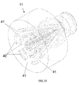
- FIG. 5 to 8 Different views of a gaseous DI injector 1 according to particular embodiments of the present invention are shown in FIG. 5 to 8 .
- a mobile part which is essentially cylindrical, is called needle or plunger 20.
- This mobile part is designed to be movable within a fixed tubular part containing an electric actuator, the solenoid or coil 16.
- the needle 20 is able to move within the nozzle 13 and to abut against a seat valve, which belongs to a fixed nozzle head 11.
- the joint between the nozzle 13 and the nozzle head 11 is provided by a nozzle seal 12.
- a guide bushing or guide bearing 21 is provided, which is contacting a first portion of the needle 22 (see FIG. 7 and 8 ).
- the material of the bushing 21 is different of the material of the needle, which is usually made of stainless steel.
- a second portion of the needle 23 is in contact with a corresponding portion of the coil support 24.
- the bushing is made of copper or an alloy thereof such as bronze, brass or similar material.
- the clearance between the bushing and the first portion of the needle is lower than the clearance between the second portion of the needle and the coil (not shown).
- the clearance between the bushing and the first portion of the needle is 4 to 8 times lower than the clearance between the second portion of the needle and the coil (for example 0.01-0.02 mm vs. 0.07-0.08 mm).
- the external area of the first portion of the needle in contact with the bushing and the external area of the second portion of the needle in contact with the coil have both a middle area 26 of smaller diameter bordered by two external areas 27 of higher diameter (see FIG. 6 ).
- a first sealing is provided by a cone-ball assembly located axially in the injector and making the valve member/valve seat assembly.
- coil 16 exerts a force on the needle 20, against the return force of spring 28, so that the ball 30 located at the extremity of the needle abuts against the seat 31which belongs to the fixed part 25 of the injector or to the nozzle head (11).
- a second sealing which is called a radial sealing
- a series of holes are machined in the tubular part of the needle which is supporting the ball at its end, for example under the form of rows of orifices 32 disposed in axial planes. These holes are provided in the needle in the region thereof in contact with the bushing 21.
- the holes of 0.4-0.7 mm diameter are obtained by electro-erosion in a number of 50 per row.
- the bushing 21 is provided on its turn with clearance axial slots 34 which are intended to cooperate with said orifices 32 of the needle 20 ( FIG. 12 ).
- the injector is closed, i.e. when the ball 30 is in contact with the nozzle seat 31 ( FIG. 10A )
- the orifices 32 of the needle and the clearance slots 34 of the bushing do not match, i.e. are not in correspondence or aligned, and a double seal is assured, firstly at the ball/seat, and secondly radially at the needle/bushing contact region.
- the orifices 32 in the needle are replaced by a number of slots 33.
- the slots 33 have the same function as the orifices 32. Slots 33 are however easier to machine than orifices 32 ( FIG. 11A, 11B and 13 ).
- nozzle heads were designed according to some embodiments supported by CFD simulations and intended to be obtained by 3D-layer manufacturing. The manufacturing of these nozzles could also be performed by the technique of lost wax foundry.
- FIG. 14 An example of a generic nozzle head 11 according to the present invention is given in FIG. 14 .
- this nozzle head 11 multi-cone channels 40 of different angles are provided (in the example shown here a 3-cone nozzle head is provided).
- interruptions 41 of the openings are provided for further reducing the dead volume of the nozzle head.
- the purpose is to obtain a gas conical jet of the highest possible diffusion angle.
- the nozzle head will be made of titanium or stainless steel.
- the ratio between the output section area and the input section area of the nozzle head is about 3.
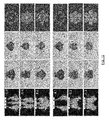
- FIG. 15 a number of simulations of gaseous fuel distribution are provided for a number of nozzle designs (further tested or to be tested) :
- the right column shows a transverse cross-sectional view of the nozzles, while the left column shows an axial cross-sectional view. Finally the two middle columns show related perspective views, according to two different view angle.
- the three first nozzle designs (C6, D4 and F4) shown on FIG. 15 show rather uniform gas mixing. Note that in some double-cone and triple-cone solutions of FIG. 15 (D.4 and F.4), cone channels 40 and cone interruptions 41 are radially alternating.
- the three further designs (A.1, E.3 and G.4) however show a central gas "hole” detrimental to homogeneous gas distribution, and which is particularly pronounced in A1 design (single cone).
Landscapes
- Engineering & Computer Science (AREA)
- Chemical & Material Sciences (AREA)
- General Chemical & Material Sciences (AREA)
- Chemical Kinetics & Catalysis (AREA)
- Combustion & Propulsion (AREA)
- Oil, Petroleum & Natural Gas (AREA)
- Mechanical Engineering (AREA)
- General Engineering & Computer Science (AREA)
- Analytical Chemistry (AREA)
- Life Sciences & Earth Sciences (AREA)
- Manufacturing & Machinery (AREA)
- Sustainable Development (AREA)
- Sustainable Energy (AREA)
- Electrochemistry (AREA)
- Fuel-Injection Apparatus (AREA)
Priority Applications (3)
| Application Number | Priority Date | Filing Date | Title |
|---|---|---|---|
| EP16188755.9A EP3296554A1 (de) | 2016-09-14 | 2016-09-14 | Nach innen öffnender injektor zur direkteinspritzung eines gasförmigen brennstoffs |
| EP17764618.9A EP3513052B1 (de) | 2016-09-14 | 2017-09-14 | Nach innen öffnender injektor zur direkteinspritzung eines gasförmigen brennstoffs |
| PCT/EP2017/073099 WO2018050731A1 (en) | 2016-09-14 | 2017-09-14 | Inward injector for direct injection of a gaseous fuel |
Applications Claiming Priority (1)
| Application Number | Priority Date | Filing Date | Title |
|---|---|---|---|
| EP16188755.9A EP3296554A1 (de) | 2016-09-14 | 2016-09-14 | Nach innen öffnender injektor zur direkteinspritzung eines gasförmigen brennstoffs |
Publications (1)
| Publication Number | Publication Date |
|---|---|
| EP3296554A1 true EP3296554A1 (de) | 2018-03-21 |
Family
ID=56926102
Family Applications (2)
| Application Number | Title | Priority Date | Filing Date |
|---|---|---|---|
| EP16188755.9A Withdrawn EP3296554A1 (de) | 2016-09-14 | 2016-09-14 | Nach innen öffnender injektor zur direkteinspritzung eines gasförmigen brennstoffs |
| EP17764618.9A Active EP3513052B1 (de) | 2016-09-14 | 2017-09-14 | Nach innen öffnender injektor zur direkteinspritzung eines gasförmigen brennstoffs |
Family Applications After (1)
| Application Number | Title | Priority Date | Filing Date |
|---|---|---|---|
| EP17764618.9A Active EP3513052B1 (de) | 2016-09-14 | 2017-09-14 | Nach innen öffnender injektor zur direkteinspritzung eines gasförmigen brennstoffs |
Country Status (2)
| Country | Link |
|---|---|
| EP (2) | EP3296554A1 (de) |
| WO (1) | WO2018050731A1 (de) |
Cited By (3)
| Publication number | Priority date | Publication date | Assignee | Title |
|---|---|---|---|---|
| EP3561286A1 (de) * | 2018-04-26 | 2019-10-30 | Volvo Car Corporation | Ansaugrohr mit integrierter wassereinspritzdüse |
| WO2023203186A1 (en) * | 2022-04-22 | 2023-10-26 | Delphi Technologies Ip Limited | Fuel injector |
| WO2024165708A1 (en) * | 2023-02-10 | 2024-08-15 | Phinia Delphi Luxembourg Sarl | Fuel injector |
Families Citing this family (2)
| Publication number | Priority date | Publication date | Assignee | Title |
|---|---|---|---|---|
| WO2019233560A1 (en) * | 2018-06-05 | 2019-12-12 | Wärtsilä Finland Oy | A gas valve unit |
| EP3803091B1 (de) * | 2018-06-05 | 2022-07-20 | Wärtsilä Finland Oy | Doppelwandige gasventileinheit |
Citations (26)
| Publication number | Priority date | Publication date | Assignee | Title |
|---|---|---|---|---|
| EP0175005A1 (de) | 1983-01-03 | 1986-03-26 | Usv Pharmaceutical Corporation | 5,6,7-Chinolincarbaminsäureester |
| EP0704620A2 (de) | 1994-10-01 | 1996-04-03 | Robert Bosch Gmbh | Brennstoffeinspritzvorrichtung |
| JPH09242615A (ja) | 1996-03-01 | 1997-09-16 | Hitachi Ltd | 気体燃料用燃料噴射弁 |
| EP1108885A2 (de) | 1999-12-15 | 2001-06-20 | Hitachi, Ltd. | Brennstoffeinspritzventil für Direkteinspritzung und mit dieser Vorrichtung ausgestatteter Verbrennungsmotor |
| WO2002012720A1 (de) | 2000-08-04 | 2002-02-14 | Robert Bosch Gmbh | Brennstoffeinspritzventil |
| US6422488B1 (en) | 1999-08-10 | 2002-07-23 | Siemens Automotive Corporation | Compressed natural gas injector having gaseous dampening for armature needle assembly during closing |
| US6508418B1 (en) * | 1998-05-27 | 2003-01-21 | Siemens Automotive Corporation | Contaminant tolerant compressed natural gas injector and method of directing gaseous fuel therethrough |
| US20030230649A1 (en) | 2002-01-17 | 2003-12-18 | Takahiro Nagaoka | Electromagnetic fuel injection valve |
| DE102005019314A1 (de) | 2005-04-26 | 2006-11-02 | Robert Bosch Gmbh | Ventil zum Steuern eines Fluids |
| WO2008005491A2 (en) | 2006-07-06 | 2008-01-10 | Continental Automotive Systems Us, Inc. | Fuel injector having an internally mounted cross-flow nozzle for enhanced compressed natural gas jet spray |
| DE102007004870A1 (de) | 2007-01-31 | 2008-08-07 | Robert Bosch Gmbh | Ventil zum Steuern von Fluiden, insbesondere Brennstoffeinspritzventil |
| DE102008001017A1 (de) * | 2008-04-07 | 2009-10-08 | Robert Bosch Gmbh | Ventil, insbesondere Gaseinblasventil, sowie Verfahren zum Öffnen eines derartigen Ventils |
| WO2010029777A1 (ja) | 2008-09-11 | 2010-03-18 | ボッシュ株式会社 | 燃料噴射装置の制御装置及び制御方法 |
| DE102008059865A1 (de) | 2008-12-01 | 2010-06-02 | Siemens Aktiengesellschaft | Injektor für flüssige und/oder gasförmige Medien |
| EP2314854A1 (de) * | 2008-08-07 | 2011-04-27 | Keihin Corporation | Brenngaseinspritzventil |
| EP2354519A2 (de) | 2010-02-02 | 2011-08-10 | Delphi Technologies, Inc. | Ventilsitz für Einspritzdüsen von gasförmigen Kraftstoffen |
| DE102012211573A1 (de) | 2012-07-04 | 2014-01-09 | Robert Bosch Gmbh | Ventil zum Steuern eines gasförmigen Mediums, insbesondere ein Einblasventil |
| JP5639426B2 (ja) | 2010-09-22 | 2014-12-10 | 株式会社ケーヒン | ガス燃料用噴射弁 |
| JP2015078625A (ja) | 2013-10-15 | 2015-04-23 | 株式会社デンソー | 燃料噴射弁 |
| DE102013222025A1 (de) | 2013-10-30 | 2015-04-30 | Robert Bosch Gmbh | Injektor, insbesondere Einblasinjektor zum Einblasen von gasförmigem Kraftstoff |
| DE102013222030A1 (de) | 2013-10-30 | 2015-04-30 | Robert Bosch Gmbh | Injektor, insbesondere Einblasinjektor für gasförmigen Kraftstoff+ |
| DE102014212562A1 (de) | 2013-10-30 | 2015-04-30 | Robert Bosch Gmbh | Injektor, insbesondere Einblasinjektor zur Direkteinblasung |
| US20150204276A1 (en) | 2014-01-17 | 2015-07-23 | Robert Bosch Gmbh | Gas injector for the direct injection of gaseous fuel into a combustion chamber |
| US20150267648A1 (en) | 2014-03-24 | 2015-09-24 | Robert Bosch Gmbh | Gas injector having two sealing regions |
| US20150267659A1 (en) | 2014-03-24 | 2015-09-24 | Robert Bosch Gmbh | Gas injector having a dual valve needle |
| US20150292440A1 (en) | 2014-04-15 | 2015-10-15 | Robert Bosch Gmbh | Directly injecting gas valve |
Family Cites Families (2)
| Publication number | Priority date | Publication date | Assignee | Title |
|---|---|---|---|---|
| GB1490416A (en) | 1974-08-27 | 1977-11-02 | American Hospital Supply Corp | Method and apparatus for determining coagulation times |
| JP4283255B2 (ja) | 2005-08-04 | 2009-06-24 | 株式会社ケーヒン | ガス燃料用噴射弁 |
-
2016
- 2016-09-14 EP EP16188755.9A patent/EP3296554A1/de not_active Withdrawn
-
2017
- 2017-09-14 EP EP17764618.9A patent/EP3513052B1/de active Active
- 2017-09-14 WO PCT/EP2017/073099 patent/WO2018050731A1/en unknown
Patent Citations (26)
| Publication number | Priority date | Publication date | Assignee | Title |
|---|---|---|---|---|
| EP0175005A1 (de) | 1983-01-03 | 1986-03-26 | Usv Pharmaceutical Corporation | 5,6,7-Chinolincarbaminsäureester |
| EP0704620A2 (de) | 1994-10-01 | 1996-04-03 | Robert Bosch Gmbh | Brennstoffeinspritzvorrichtung |
| JPH09242615A (ja) | 1996-03-01 | 1997-09-16 | Hitachi Ltd | 気体燃料用燃料噴射弁 |
| US6508418B1 (en) * | 1998-05-27 | 2003-01-21 | Siemens Automotive Corporation | Contaminant tolerant compressed natural gas injector and method of directing gaseous fuel therethrough |
| US6422488B1 (en) | 1999-08-10 | 2002-07-23 | Siemens Automotive Corporation | Compressed natural gas injector having gaseous dampening for armature needle assembly during closing |
| EP1108885A2 (de) | 1999-12-15 | 2001-06-20 | Hitachi, Ltd. | Brennstoffeinspritzventil für Direkteinspritzung und mit dieser Vorrichtung ausgestatteter Verbrennungsmotor |
| WO2002012720A1 (de) | 2000-08-04 | 2002-02-14 | Robert Bosch Gmbh | Brennstoffeinspritzventil |
| US20030230649A1 (en) | 2002-01-17 | 2003-12-18 | Takahiro Nagaoka | Electromagnetic fuel injection valve |
| DE102005019314A1 (de) | 2005-04-26 | 2006-11-02 | Robert Bosch Gmbh | Ventil zum Steuern eines Fluids |
| WO2008005491A2 (en) | 2006-07-06 | 2008-01-10 | Continental Automotive Systems Us, Inc. | Fuel injector having an internally mounted cross-flow nozzle for enhanced compressed natural gas jet spray |
| DE102007004870A1 (de) | 2007-01-31 | 2008-08-07 | Robert Bosch Gmbh | Ventil zum Steuern von Fluiden, insbesondere Brennstoffeinspritzventil |
| DE102008001017A1 (de) * | 2008-04-07 | 2009-10-08 | Robert Bosch Gmbh | Ventil, insbesondere Gaseinblasventil, sowie Verfahren zum Öffnen eines derartigen Ventils |
| EP2314854A1 (de) * | 2008-08-07 | 2011-04-27 | Keihin Corporation | Brenngaseinspritzventil |
| WO2010029777A1 (ja) | 2008-09-11 | 2010-03-18 | ボッシュ株式会社 | 燃料噴射装置の制御装置及び制御方法 |
| DE102008059865A1 (de) | 2008-12-01 | 2010-06-02 | Siemens Aktiengesellschaft | Injektor für flüssige und/oder gasförmige Medien |
| EP2354519A2 (de) | 2010-02-02 | 2011-08-10 | Delphi Technologies, Inc. | Ventilsitz für Einspritzdüsen von gasförmigen Kraftstoffen |
| JP5639426B2 (ja) | 2010-09-22 | 2014-12-10 | 株式会社ケーヒン | ガス燃料用噴射弁 |
| DE102012211573A1 (de) | 2012-07-04 | 2014-01-09 | Robert Bosch Gmbh | Ventil zum Steuern eines gasförmigen Mediums, insbesondere ein Einblasventil |
| JP2015078625A (ja) | 2013-10-15 | 2015-04-23 | 株式会社デンソー | 燃料噴射弁 |
| DE102013222025A1 (de) | 2013-10-30 | 2015-04-30 | Robert Bosch Gmbh | Injektor, insbesondere Einblasinjektor zum Einblasen von gasförmigem Kraftstoff |
| DE102013222030A1 (de) | 2013-10-30 | 2015-04-30 | Robert Bosch Gmbh | Injektor, insbesondere Einblasinjektor für gasförmigen Kraftstoff+ |
| DE102014212562A1 (de) | 2013-10-30 | 2015-04-30 | Robert Bosch Gmbh | Injektor, insbesondere Einblasinjektor zur Direkteinblasung |
| US20150204276A1 (en) | 2014-01-17 | 2015-07-23 | Robert Bosch Gmbh | Gas injector for the direct injection of gaseous fuel into a combustion chamber |
| US20150267648A1 (en) | 2014-03-24 | 2015-09-24 | Robert Bosch Gmbh | Gas injector having two sealing regions |
| US20150267659A1 (en) | 2014-03-24 | 2015-09-24 | Robert Bosch Gmbh | Gas injector having a dual valve needle |
| US20150292440A1 (en) | 2014-04-15 | 2015-10-15 | Robert Bosch Gmbh | Directly injecting gas valve |
Cited By (3)
| Publication number | Priority date | Publication date | Assignee | Title |
|---|---|---|---|---|
| EP3561286A1 (de) * | 2018-04-26 | 2019-10-30 | Volvo Car Corporation | Ansaugrohr mit integrierter wassereinspritzdüse |
| WO2023203186A1 (en) * | 2022-04-22 | 2023-10-26 | Delphi Technologies Ip Limited | Fuel injector |
| WO2024165708A1 (en) * | 2023-02-10 | 2024-08-15 | Phinia Delphi Luxembourg Sarl | Fuel injector |
Also Published As
| Publication number | Publication date |
|---|---|
| EP3513052B1 (de) | 2020-07-01 |
| WO2018050731A1 (en) | 2018-03-22 |
| EP3513052A1 (de) | 2019-07-24 |
Similar Documents
| Publication | Publication Date | Title |
|---|---|---|
| EP3513052B1 (de) | Nach innen öffnender injektor zur direkteinspritzung eines gasförmigen brennstoffs | |
| US7891579B2 (en) | Gaseous fuel injector using liquid fuel as lubricant and pressure-transmitting medium | |
| US8800529B2 (en) | Dual fuel injection valve | |
| KR101677862B1 (ko) | 연료 가스 분사 밸브, 듀얼 퓨얼 가스 엔진 및 연료 가스 분사 방법 | |
| US8944027B2 (en) | Dual fuel injection compression ignition engine and method of operating same | |
| US10294876B2 (en) | Method of injecting fuel into the combustion chamber of an internal-combustion engine running in single-fuel or multi-fuel mode | |
| US20160123286A1 (en) | Method, system, and fuel injector for multi-fuel injection with pressure intensification and a variable orifice | |
| US20130213358A1 (en) | Fuel injector capable of dual fuel injection | |
| US20140373806A1 (en) | Fuel injector for multi-fuel injection with pressure intensification and a variable orifice | |
| US20060081722A1 (en) | Gaseous fuel injector for internal combustion engine | |
| US20240093635A1 (en) | An internal combustion engine and ignition system with a pre-chamber | |
| CN110953067B (zh) | 发动机及其双射流燃烧方法 | |
| CN114109587A (zh) | 燃烧装置及系统 | |
| US20170335761A1 (en) | Multi-fuel internal combustion engine, fuel systems and related methods | |
| CN109681348A (zh) | 一种中速发动机双燃料喷油器 | |
| JP5163530B2 (ja) | 圧縮着火内燃機関 | |
| US10900450B1 (en) | Fuel system, fuel injector nozzle assembly, and engine head assembly structured for ducted fuel injection | |
| CN203067140U (zh) | 多功能隔板及包括多功能隔板的组件 | |
| US20240318608A1 (en) | Apparatus and method for injecting a pilot fuel into an internal combustion engine | |
| EP4230860A1 (de) | Brennstoffventil für einen grossen turbogeladenen zweitakt-kreuzkopfverbrennungsmotor | |
| WO2019100035A1 (en) | Efficiency and emissions improvements for natural gas conversions of emd 2-cycle medium speed engines | |
| CN216665738U (zh) | 燃烧装置及系统 | |
| CN216894617U (zh) | 燃烧系统及发动机 | |
| JP5316868B2 (ja) | ディーゼルエンジン | |
| WO2023110127A1 (en) | A nozzle cap, a fuel gas injection and a hydrogen internal combustion engine |
Legal Events
| Date | Code | Title | Description |
|---|---|---|---|
| PUAI | Public reference made under article 153(3) epc to a published international application that has entered the european phase |
Free format text: ORIGINAL CODE: 0009012 |
|
| AK | Designated contracting states |
Kind code of ref document: A1 Designated state(s): AL AT BE BG CH CY CZ DE DK EE ES FI FR GB GR HR HU IE IS IT LI LT LU LV MC MK MT NL NO PL PT RO RS SE SI SK SM TR |
|
| AX | Request for extension of the european patent |
Extension state: BA ME |
|
| STAA | Information on the status of an ep patent application or granted ep patent |
Free format text: STATUS: THE APPLICATION IS DEEMED TO BE WITHDRAWN |
|
| 18D | Application deemed to be withdrawn |
Effective date: 20180922 |