EP3296529A1 - Valve opening and closing timing control apparatus - Google Patents
Valve opening and closing timing control apparatus Download PDFInfo
- Publication number
- EP3296529A1 EP3296529A1 EP17190997.1A EP17190997A EP3296529A1 EP 3296529 A1 EP3296529 A1 EP 3296529A1 EP 17190997 A EP17190997 A EP 17190997A EP 3296529 A1 EP3296529 A1 EP 3296529A1
- Authority
- EP
- European Patent Office
- Prior art keywords
- drive shaft
- inner gear
- peripheral surface
- valve opening
- gear
- Prior art date
- Legal status (The legal status is an assumption and is not a legal conclusion. Google has not performed a legal analysis and makes no representation as to the accuracy of the status listed.)
- Granted
Links
- 238000006073 displacement reaction Methods 0.000 claims abstract description 37
- 230000007246 mechanism Effects 0.000 claims abstract description 23
- 230000002093 peripheral effect Effects 0.000 claims description 57
- 230000009467 reduction Effects 0.000 claims description 11
- 238000002485 combustion reaction Methods 0.000 claims description 5
- 238000009987 spinning Methods 0.000 claims description 2
- 230000001105 regulatory effect Effects 0.000 description 10
- 238000005461 lubrication Methods 0.000 description 5
- 230000004043 responsiveness Effects 0.000 description 4
- 230000002159 abnormal effect Effects 0.000 description 3
- 230000006866 deterioration Effects 0.000 description 3
- 230000004044 response Effects 0.000 description 3
- 230000008859 change Effects 0.000 description 2
- 238000006243 chemical reaction Methods 0.000 description 2
- 238000005516 engineering process Methods 0.000 description 2
- 238000004519 manufacturing process Methods 0.000 description 2
- 230000005540 biological transmission Effects 0.000 description 1
- 230000008878 coupling Effects 0.000 description 1
- 238000010168 coupling process Methods 0.000 description 1
- 238000005859 coupling reaction Methods 0.000 description 1
- 230000006872 improvement Effects 0.000 description 1
- 239000010687 lubricating oil Substances 0.000 description 1
- 239000003921 oil Substances 0.000 description 1
- 238000003825 pressing Methods 0.000 description 1
- 238000000926 separation method Methods 0.000 description 1
Images


Classifications
-
- F—MECHANICAL ENGINEERING; LIGHTING; HEATING; WEAPONS; BLASTING
- F01—MACHINES OR ENGINES IN GENERAL; ENGINE PLANTS IN GENERAL; STEAM ENGINES
- F01L—CYCLICALLY OPERATING VALVES FOR MACHINES OR ENGINES
- F01L1/00—Valve-gear or valve arrangements, e.g. lift-valve gear
- F01L1/34—Valve-gear or valve arrangements, e.g. lift-valve gear characterised by the provision of means for changing the timing of the valves without changing the duration of opening and without affecting the magnitude of the valve lift
- F01L1/344—Valve-gear or valve arrangements, e.g. lift-valve gear characterised by the provision of means for changing the timing of the valves without changing the duration of opening and without affecting the magnitude of the valve lift changing the angular relationship between crankshaft and camshaft, e.g. using helicoidal gear
- F01L1/3442—Valve-gear or valve arrangements, e.g. lift-valve gear characterised by the provision of means for changing the timing of the valves without changing the duration of opening and without affecting the magnitude of the valve lift changing the angular relationship between crankshaft and camshaft, e.g. using helicoidal gear using hydraulic chambers with variable volume to transmit the rotating force
-
- F—MECHANICAL ENGINEERING; LIGHTING; HEATING; WEAPONS; BLASTING
- F16—ENGINEERING ELEMENTS AND UNITS; GENERAL MEASURES FOR PRODUCING AND MAINTAINING EFFECTIVE FUNCTIONING OF MACHINES OR INSTALLATIONS; THERMAL INSULATION IN GENERAL
- F16K—VALVES; TAPS; COCKS; ACTUATING-FLOATS; DEVICES FOR VENTING OR AERATING
- F16K31/00—Actuating devices; Operating means; Releasing devices
- F16K31/02—Actuating devices; Operating means; Releasing devices electric; magnetic
- F16K31/04—Actuating devices; Operating means; Releasing devices electric; magnetic using a motor
- F16K31/041—Actuating devices; Operating means; Releasing devices electric; magnetic using a motor for rotating valves
- F16K31/043—Actuating devices; Operating means; Releasing devices electric; magnetic using a motor for rotating valves characterised by mechanical means between the motor and the valve, e.g. lost motion means reducing backlash, clutches, brakes or return means
-
- F—MECHANICAL ENGINEERING; LIGHTING; HEATING; WEAPONS; BLASTING
- F01—MACHINES OR ENGINES IN GENERAL; ENGINE PLANTS IN GENERAL; STEAM ENGINES
- F01L—CYCLICALLY OPERATING VALVES FOR MACHINES OR ENGINES
- F01L1/00—Valve-gear or valve arrangements, e.g. lift-valve gear
- F01L1/02—Valve drive
- F01L1/04—Valve drive by means of cams, camshafts, cam discs, eccentrics or the like
- F01L1/047—Camshafts
-
- F—MECHANICAL ENGINEERING; LIGHTING; HEATING; WEAPONS; BLASTING
- F01—MACHINES OR ENGINES IN GENERAL; ENGINE PLANTS IN GENERAL; STEAM ENGINES
- F01L—CYCLICALLY OPERATING VALVES FOR MACHINES OR ENGINES
- F01L1/00—Valve-gear or valve arrangements, e.g. lift-valve gear
- F01L1/34—Valve-gear or valve arrangements, e.g. lift-valve gear characterised by the provision of means for changing the timing of the valves without changing the duration of opening and without affecting the magnitude of the valve lift
- F01L1/344—Valve-gear or valve arrangements, e.g. lift-valve gear characterised by the provision of means for changing the timing of the valves without changing the duration of opening and without affecting the magnitude of the valve lift changing the angular relationship between crankshaft and camshaft, e.g. using helicoidal gear
- F01L1/352—Valve-gear or valve arrangements, e.g. lift-valve gear characterised by the provision of means for changing the timing of the valves without changing the duration of opening and without affecting the magnitude of the valve lift changing the angular relationship between crankshaft and camshaft, e.g. using helicoidal gear using bevel or epicyclic gear
-
- F—MECHANICAL ENGINEERING; LIGHTING; HEATING; WEAPONS; BLASTING
- F16—ENGINEERING ELEMENTS AND UNITS; GENERAL MEASURES FOR PRODUCING AND MAINTAINING EFFECTIVE FUNCTIONING OF MACHINES OR INSTALLATIONS; THERMAL INSULATION IN GENERAL
- F16K—VALVES; TAPS; COCKS; ACTUATING-FLOATS; DEVICES FOR VENTING OR AERATING
- F16K31/00—Actuating devices; Operating means; Releasing devices
- F16K31/02—Actuating devices; Operating means; Releasing devices electric; magnetic
- F16K31/04—Actuating devices; Operating means; Releasing devices electric; magnetic using a motor
- F16K31/047—Actuating devices; Operating means; Releasing devices electric; magnetic using a motor characterised by mechanical means between the motor and the valve, e.g. lost motion means reducing backlash, clutches, brakes or return means
- F16K31/048—Actuating devices; Operating means; Releasing devices electric; magnetic using a motor characterised by mechanical means between the motor and the valve, e.g. lost motion means reducing backlash, clutches, brakes or return means with torque limiters
-
- F—MECHANICAL ENGINEERING; LIGHTING; HEATING; WEAPONS; BLASTING
- F01—MACHINES OR ENGINES IN GENERAL; ENGINE PLANTS IN GENERAL; STEAM ENGINES
- F01L—CYCLICALLY OPERATING VALVES FOR MACHINES OR ENGINES
- F01L1/00—Valve-gear or valve arrangements, e.g. lift-valve gear
- F01L1/34—Valve-gear or valve arrangements, e.g. lift-valve gear characterised by the provision of means for changing the timing of the valves without changing the duration of opening and without affecting the magnitude of the valve lift
- F01L1/344—Valve-gear or valve arrangements, e.g. lift-valve gear characterised by the provision of means for changing the timing of the valves without changing the duration of opening and without affecting the magnitude of the valve lift changing the angular relationship between crankshaft and camshaft, e.g. using helicoidal gear
- F01L1/3442—Valve-gear or valve arrangements, e.g. lift-valve gear characterised by the provision of means for changing the timing of the valves without changing the duration of opening and without affecting the magnitude of the valve lift changing the angular relationship between crankshaft and camshaft, e.g. using helicoidal gear using hydraulic chambers with variable volume to transmit the rotating force
- F01L2001/3445—Details relating to the hydraulic means for changing the angular relationship
-
- F—MECHANICAL ENGINEERING; LIGHTING; HEATING; WEAPONS; BLASTING
- F01—MACHINES OR ENGINES IN GENERAL; ENGINE PLANTS IN GENERAL; STEAM ENGINES
- F01L—CYCLICALLY OPERATING VALVES FOR MACHINES OR ENGINES
- F01L2250/00—Camshaft drives characterised by their transmission means
- F01L2250/02—Camshaft drives characterised by their transmission means the camshaft being driven by chains
-
- F—MECHANICAL ENGINEERING; LIGHTING; HEATING; WEAPONS; BLASTING
- F01—MACHINES OR ENGINES IN GENERAL; ENGINE PLANTS IN GENERAL; STEAM ENGINES
- F01L—CYCLICALLY OPERATING VALVES FOR MACHINES OR ENGINES
- F01L2250/00—Camshaft drives characterised by their transmission means
- F01L2250/04—Camshaft drives characterised by their transmission means the camshaft being driven by belts
-
- F—MECHANICAL ENGINEERING; LIGHTING; HEATING; WEAPONS; BLASTING
- F01—MACHINES OR ENGINES IN GENERAL; ENGINE PLANTS IN GENERAL; STEAM ENGINES
- F01L—CYCLICALLY OPERATING VALVES FOR MACHINES OR ENGINES
- F01L2311/00—Differential gears located between crankshafts and camshafts for varying the timing of valves
-
- F—MECHANICAL ENGINEERING; LIGHTING; HEATING; WEAPONS; BLASTING
- F01—MACHINES OR ENGINES IN GENERAL; ENGINE PLANTS IN GENERAL; STEAM ENGINES
- F01L—CYCLICALLY OPERATING VALVES FOR MACHINES OR ENGINES
- F01L2810/00—Arrangements solving specific problems in relation with valve gears
- F01L2810/04—Reducing noise
-
- F—MECHANICAL ENGINEERING; LIGHTING; HEATING; WEAPONS; BLASTING
- F01—MACHINES OR ENGINES IN GENERAL; ENGINE PLANTS IN GENERAL; STEAM ENGINES
- F01L—CYCLICALLY OPERATING VALVES FOR MACHINES OR ENGINES
- F01L2820/00—Details on specific features characterising valve gear arrangements
- F01L2820/03—Auxiliary actuators
- F01L2820/032—Electric motors
Abstract
Description
- This disclosure relates to a valve opening and closing timing control apparatus, which sets a relative rotation phase between a driving side rotator and a driven side rotator by a driving force of an electric actuator.
- As a valve opening and closing timing control apparatus having the configuration described above,
JP 2008-038886A - In this technology, a biasing member (a spring member in Reference 1) is disposed so as to be fitted into a region of the outer periphery of the drive shaft that corresponds to the area in which the external toothed portion of the inner gear is engaged with the internal toothed portion of the ring gear. Thereby, a biasing force is applied to the direction in which the internal toothed portion and the external toothed portion are engaged with each other. In particular,
Reference 1 describes that a biasing direction of the biasing member is set so as to offset a fluctuation torque applied from an intake valve. - In the configuration described in
Reference 1, the biasing force of the biasing member is set so as to allow the ring gear and the inner gear to maintain the engaged state thereof against an engagement reaction force. Thus, the internal toothed portion and the external toothed portion come into strong contact with each other, which increases engagement loss. - In addition, in a configuration in which the outer periphery of the drive shaft is brought into contact with the inner periphery of the inner gear over a long area, the frictional resistance of the contact area is increased by the biasing force of the biasing member. For this reason, when the electric actuator is driven, the rotational speed is suppressed, causing deterioration in responsiveness, and there is room for improvement.
- Thus, a need exists for a valve opening and closing timing control apparatus, which maintains sufficient engagement between the ring gear and the inner gear and increases a response speed.
- A feature of an aspect of this disclosure resides in that a valve opening and closing timing control apparatus includes a driving side rotator disposed rotatably about a rotation axis and configured to rotate synchronously with a crankshaft of an internal combustion engine, a driven side rotator disposed rotatably about the rotation axis and configured to be rotatable relative to the driving side rotator and to rotate integrally with a valve opening/closing camshaft of the internal combustion engine, and a phase adjustment mechanism configured to set a relative rotation phase between the driving side rotator and the driven side rotator by a driving force of an electric actuator, wherein the phase adjustment mechanism includes an internal toothed ring gear disposed coaxially with the rotation axis, an inner gear disposed coaxially with an eccentric axis in a posture parallel to the rotation axis such that an external toothed portion thereof is engaged with a portion of an internal toothed portion of the ring gear, and a drive shaft fitted into the inner gear, wherein the phase adjustment mechanism is configured with a differential speed reduction mechanism in which the drive shaft is rotated about the rotation axis by the driving force of the electric actuator such that the inner gear revolves around the rotation axis while spinning on the eccentric axis, and wherein the valve opening and closing timing control apparatus further includes a biasing member provided on an outer periphery of the drive shaft to apply a biasing force in a direction such that the external toothed portion of the inner gear is engaged with the internal toothed portion of the ring gear, and a displacement regulation portion configured to regulate a displacement of the inner gear on the basis of the drive shaft in a biasing direction of the biasing member.
- With this configuration, because displacement of the inner gear on the basis of the drive shaft in the direction in which the inner gear is engaged with the ring gear by the biasing force of the biasing member is regulated by the displacement regulation portion, the engagement depth of the internal toothed portion and the external toothed portion may be maintained to a predetermined value. In addition, through the provision of the displacement regulation portion, because contact surface pressures of the internal toothed portion and the external toothed portion may be reduced and it is unnecessary to greatly deform the biasing member (because the actual operation distance may be reduced), the durability of the biasing member is increased. In addition, because it is unnecessary to bring the outer periphery of the drive shaft into contact with the inner periphery of the inner gear over a wide area, resistance caused when the drive shaft is rotated may be reduced.
- Accordingly, the valve opening and closing timing control apparatus is configured so as to reduce the biasing force of the biasing member and to increase a response speed while maintaining good engagement of the ring gear and the inner gear.
- As another configuration, the displacement regulation portion may be formed by a contact portion, which protrudes from an outer peripheral surface of the drive shaft at a side opposite to the biasing member with the eccentric axis interposed therebetween so as to be brought into contact with an inner peripheral surface of the inner gear.
- Accordingly, when the contact portion protrudes from a portion of the outer peripheral surface of the drive shaft, displacement of the inner gear in the direction in which the inner gear is engaged with the ring gear is regulated and the contact area of the drive shaft and the inner gear is reduced, which enables a reduction in resistance upon relative rotation of the drive shaft and the inner gear.
- As another configuration, the displacement regulation portion may be formed by contact portions, which protrude from an outer peripheral surface of the drive shaft at two positions, which equally receive a pressure from the drive shaft at a side opposite to the biasing member with the eccentric axis interposed therebetween, so as to be brought into contact with an inner peripheral surface of the inner gear.
- With this configuration, when the contact portions protrude from a portion of the outer peripheral surface of the drive shaft, displacement of the inner gear in the direction in which the inner gear is engaged with the ring gear is regulated and the contact area of the drive shaft and the inner gear is reduced, which enables a reduction in resistance upon relative rotation of the drive shaft and the inner gear. In addition, in this configuration, because the contact portions are provided at two positions, the posture of the inner gear may be stabilized. Moreover, because the contact portions provided at two positions equally receive a pressure from the drive shaft, surface pressures of the internal toothed portion and the external toothed portion may be equally reduced, which ensures smooth change in engagement position.
- As another configuration, the displacement regulation portion may be configured by setting an outer diameter of an outer peripheral surface of the drive shaft at a side opposite to the biasing member with the eccentric axis interposed therebetween to the same value as an inner diameter of an inner peripheral surface of the inner gear.
- With this configuration, deterioration in strength may not be caused because the diameter of the drive shaft is not reduced, and a gap between the outer periphery of the drive shaft and the inner periphery of the inner gear is reduced, which allows a lubrication oil to be held in the gap. In addition, in this configuration, manufacture becomes easy compared that a protrusion is provided on the outer periphery of the drive shaft.
- As another configuration, the inner gear may be provided with a ring-shaped bearing on an inner periphery thereof so that an inner peripheral surface of the bearing functions as the inner peripheral surface of the inner gear.
- With this configuration, even in a configuration in which a bearing such as a ball bearing, etc. is provided, when the inner periphery of the bearing functions as the inner periphery of the inner gear, the biasing force of the biasing member may be reduced, which may maintain good engagement between the ring gear and the inner gear and may increase a response speed.
- The foregoing and additional features and characteristics of this disclosure will become more apparent from the following detailed description considered with the reference to the accompanying drawings, wherein:
-
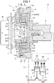
Fig. 1 is a cross-sectional view illustrating a valve opening and closing timing control apparatus; -
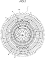
Fig. 2 is a cross-sectional view taken along line II-II ofFig. 1 ; -
Fig. 3 is a cross-sectional view taken along line III-III ofFig. 1 ; -
Fig. 4 is an exploded perspective view of the valve opening and closing timing control apparatus; -
Fig. 5 is an enlarged cross-sectional view illustrating a relationship between a displacement regulation portion and a biasing direction of a spring; -
Fig. 6 is an enlarged cross sectional view illustrating the displacement regulation portion according to another embodiment (a); and -
Fig. 7 is an enlarged cross sectional view illustrating the displacement regulation portion according to a further embodiment (b). - Hereinafter, embodiments disclosed here will be described with reference to the accompanying drawings.
- As illustrated in
Figs. 1 to 4 , a valve opening and closingtiming control apparatus 1 includes a driving side rotator A, which rotates synchronously with acrankshaft 2 of an engine E that is an internal combustion engine, a driven side rotator B, which rotates integrally with anintake camshaft 3, and a phase adjustment mechanism C, which sets a relative rotation phase between the driving side rotator A and the driven side rotator B by a driving force of a phase control motor M (an example of an electric actuator). - The engine E is configured in a four-cycle form in which
pistons 4 are accommodated in a plurality of cylinder bores formed in a cylinder block and eachpiston 4 is connected to thecrankshaft 2 via a connectingrod 5. A timing belt 6 (this may also be referred to as a timing chain) is wound around anoutput pulley 2S of thecrankshaft 2 of the engine E and adriving pulley 11S of the driving side rotator A. - Therefore, when the engine E operates, the entire valve opening and closing
timing control apparatus 1 rotates around a rotation axis X. In addition, the driven side rotator B is configured to be displaceable in the same rotation direction or in the reverse direction relative to the driving side rotator A by driving of the phase adjustment mechanism C. - In the valve opening and closing
timing control apparatus 1, the driving of the phase control motor M is controlled by a control device such as an ECU, etc. The phase adjustment mechanism C sets a relative rotation phase between the driving side rotator A and the driven side rotator B under this control, and with this setting, the control of the opening/closing timing ofintake valves 3B is realized bycam portions 3A of theintake camshaft 3. - In the driving side rotator A, an
outer case 11, which is provided with thedriving pulley 11S, and afront plate 12 are fastened to each other using a plurality offastening bolts 13. In the inner space of theouter case 11, the driven side rotator B and the phase adjustment mechanism C, which is configured with a hypotrochoid-type speed reduction gear (a concrete example of a differential speed reduction mechanism), are accommodated. - The driven side rotator B is configured with a
ring gear 21, which is provided with aninternal toothed portion 21A having a plurality of internal teeth. The phase adjustment mechanism C includes thering gear 21, aninner gear 22, which is provided with anexternal toothed portion 22A having a plurality of external teeth engaged with theinternal toothed portion 21A of thering gear 21, adrive shaft 24 fitted into theinner gear 22, and ajoint member 30 as a link mechanism that links theinner gear 22 to the driving side rotator A. - As illustrated in
Fig. 2 , thering gear 21 is disposed coaxially with the rotation axis X, and theinner gear 22 is disposed coaxially with an eccentric axis Y, which has a posture parallel to the rotation axis X. A portion of theexternal toothed portion 22A is engaged with a portion of theinternal toothed portion 21A of thering gear 21, and the number of teeth of theexternal toothed portion 22A of theinner gear 22 is set to be smaller than the number of teeth of theinternal toothed portion 21A of thering gear 21 by one tooth. - As illustrated in
Figs. 1 to 4 , the phase control motor M (electric motor) is supported on the engine E by asupport frame 7 such that an output shaft Ma thereof is disposed coaxially with the rotation axis X. - The
ring gear 21 has a structure in which a drivenplate 21P, which has a posture orthogonal to the rotation axis X, is integrated with a ring-shaped portion on which theinternal toothed portion 21A is formed. As aconnection bolt 35 is inserted through ahole 24C in the center of the drivenplate 21P and is screwed to theintake camshaft 3, thering gear 21 is connected to theintake camshaft 3 so as to be located coaxially with the rotation axis X. - The
drive shaft 24 is provided with afirst support portion 24A having an outer peripheral surface about rotation axis X, on the outer end side thereof in the direction along the rotation axis X, and is provided with asecond support portion 24B having an outer peripheral surface about the eccentric axis Y, on the inner end side thereof. Onenotch 24D is formed in the outer periphery of thesecond support portion 24B, and aspring 25, which serves as a biasing member, is fitted into thenotch 24D. In addition, thehole 24C is formed in thedrive shaft 24 about the rotation axis X, and a pair ofengaging grooves 24T, into which anengaging member 28 of the output shaft Ma of the phase control motor M is engaged, is formed in thehole 24C so as to have a posture parallel to the rotation axis X. - Moreover, a
single lubrication groove 24G, which has a posture parallel to the rotation axis X, is formed in thehole 24C, and alubrication flow path 24R is formed to penetrate from thelubrication groove 24G to the outer surface. A pair oflubrication flow paths 24R is formed to penetrate from the pair ofengaging grooves 24T to the outer surface. - As illustrated in
Fig. 1 , a first bearing 26, which is configured with a ball bearing, is disposed between an opening in the center of thefront plate 12 and thefirst support portion 24A, so that thedrive shaft 24 is supported to be rotatable relative to the driving side rotator A about the rotation axis X. - As illustrated in
Fig. 2 , a second bearing 27, which is configured with a ball bearing, is disposed between the inner periphery of theinner gear 22 and thesecond support portion 24B of thedrive shaft 24, so that thesecond support portion 24B and theinner gear 22 are rotatable relative to each other about the eccentric axis Y. In addition, the biasing force of thespring 25 is applied to the inner peripheral surface S of thesecond bearing 27. Moreover, when a C-ring 29 as a stop ring is provided, separation of thesecond bearing 27 from thesecond support portion 24B is prevented (seeFigs. 1 and4 ). - Therefore, the
inner gear 22 is rotatably supported about the eccentric axis Y, and as illustrated inFig. 2 , a portion of the externaltoothed portion 22A is engaged with a portion of the internaltoothed portion 21A of thering gear 21, and the engagement is maintained by the biasing force of thespring 25. In addition, an operation mode of setting a relative rotational phase between the driving side rotator A and the driven side rotator B by the valve opening and closingtiming control apparatus 1 will be described below. - As illustrated in
Fig. 4 , thejoint member 30, which constitutes the link mechanism, is manufactured by, for example, pressing a plate member. In thejoint member 30, a pair of firstengaging arms 31, which protrudes outward about the rotation axis X, a pair of secondengaging arms 32, which protrudes in the direction orthogonal to the first engagingarms 31, and a ring-shapedportion 33, which interconnects the same, are integrally formed with one another. The secondengaging arms 32 are provided respectively with engagingrecesses 32A, which are open toward the rotation axis X. - When viewing the
joint member 30 in the direction along the rotation axis X, the first engagingarms 31 are configured with plate-shaped areas, which linearly extend in a first direction, and the engagingrecesses 32A of the secondengaging arms 32 are concavely formed so as to be recessed in a second direction orthogonal to the first direction. In addition, the pair of firstengaging arms 31, the pair of secondengaging arms 32 and the ring-shapedportion 33 interconnecting the same are disposed in an imaginary plane orthogonal to the rotation axis X. - The
outer case 11, which constitutes the driving side rotator A, is provided, with a pair of first link portions AT, which are formed in a through-hole shape to extend in the radial direction about the rotation axis X from the inner space to the outer space of theouter case 11, on a connection surface thereof, which is in contact with thefront plate 12. The straight direction in which the pair of first link portions AT is arranged parallel to each other is the first direction (the horizontal direction inFig. 3 ). In addition, theinner gear 22 is provided with a pair ofsecond link portions 22T, which is formed in a protrusion shape at positions facing each other with the eccentric axis Y interposed therebetween, on the end surface thereof. The direction in which the pair ofsecond link portions 22T is arranged parallel to each other is the second direction (the vertical direction inFig. 3 ). - As illustrated in
Figs. 3 and4 , each first link portion AT is provided with a pair of first guide surfaces G1, which has a posture parallel to the first direction when viewing in the direction along the rotation axis X. In addition, eachsecond link portion 22T is formed as a rectangular portion having a pair of second guide surfaces G2, which has a posture parallel to the second direction when viewing in the direction along the rotation axis X. - With this configuration, when the first engaging
arms 31 of thejoint member 30 are engaged with the first link portions AT and the engagingrecesses 32A of the secondengaging arms 32 of thejoint member 30 are engaged with thesecond link portions 22T, thelink member 30 may function as an Oldham's coupling. - In addition, in this configuration, there is a positional relationship in which linear portions of the first engaging
arms 31 come into contact with the first guide surfaces G1 of the first link portions AT and linear portions of the recesses of the secondengaging arms 32 come into contact with the second guide surfaces G2 of thesecond link portions 22T. - As illustrated in
Fig. 4 , the recessed depth L1 of the first link portion AT is set to a sufficiently larger value than the thickness L2 of the firstengaging arm 31. Thus, when the front surface of the firstengaging arm 31 and thefront plate 12 come into contact with each other, a gap is formed between the rear surface of the firstengaging arm 31 and the bottom portion of the first link portion AT. - Moreover, a plurality of
protrusions 12A protrudes from the inner surface of thefront plate 12 and determines the position of thering gear 21 in the direction along the rotation axis X by coming into contact with the end surface of thering gear 21. - In the valve opening and closing
timing control apparatus 1, a control device (not illustrated) is provided to control the phase control motor M, and when maintaining a relative rotational phase between the driving side rotator A and the driven side rotator B, thedrive shaft 24 is rotated at the same speed as the rotation speed of theintake camshaft 3. - On the other hand, when setting a relative rotational phase between the driving side rotator A and the driven side rotator B to a target phase, the output shaft Ma of the phase control motor M is rotated at a higher or lower speed than the rotation speed of the
intake camshaft 3. - Therefore, the eccentric axis Y of the
second support portion 24B revolves around the rotation axis X, and with this revolution, the engagement position of the internaltoothed portion 21A of thering gear 21 with respect to the externaltoothed portion 22A of theinner gear 22 is displaced along the inner periphery of thering gear 21, and simultaneously, theinner gear 22 spins on the eccentric axis Y. - When the eccentric axis Y of the
inner gear 22 revolves around the rotation axis X, because the displacement of theinner gear 22 is transmitted from thesecond link portion 22T to theengaging recess 32A, thejoint member 30 operates to be displaced in the first direction and the second direction so that the driven side rotator B is rotated relative to the driving side rotator A by an angle that corresponds to the amount of relative displacement between thering gear 21 and theinner gear 22, whereby the control of the valve opening/closing time is realized. - Specifically, because the number of teeth of the external
toothed portion 22A of theinner gear 22 is set to be smaller by only one tooth than the number of teeth of the internaltoothed portion 21A of thering gear 21, when the eccentric axis Y of theinner gear 22 revolves once around the rotation axis X, a speed reduction transmission state where a rotational force is applied to thering gear 21 by an angle that corresponds to one tooth is obtained to realize large speed reduction. - In addition, upon this speed reduction, because the relative rotation between the
inner gear 22 and theouter case 11, which constitutes the driving side rotator A, is regulated by thejoint member 30, thering gear 21 is rotated about the rotation axis X by the rotational force acting such that theinner gear 22 spins as theinner gear 22 revolves. That is, as theinner gear 22 revolves with respect to thering gear 21, thering gear 21 is rotated on the basis of the driving side rotator A, and consequently, a relative rotation phase between the driving side rotator A and the driven side rotator B is set to realize the setting of the opening/closing time by theintake camshaft 3. - The valve opening and closing
timing control apparatus 1 is disposed inside a case of a chain, which is driven by theintake camshaft 3 and an exhaust camshaft of the engine E. With such a positional relationship, some of a lubricating oil supplied to the camshaft or the chain moves from the opening in the center of thefront plate 12 into thehole 24C in thedrive shaft 24 to thereby be supplied to each part in the inner space of theouter case 11, thereby ensuring smooth operation of the phase adjustment mechanism C. - As illustrated in
Fig. 2 , in this embodiment, although the inner peripheral surface S of the second baring functions as the inner peripheral surface of theinner gear 22 because thesecond bearing 27, which is formed in a ring shape, is fitted into the inner peripheral surface of theinner gear 22, a configuration in which thespring 25 comes into contact with the inner peripheral surface of theinner gear 22 without using thesecond bearing 27 may be adopted. - In addition, in this embodiment, because the inner peripheral surface S of the
second bearing 27 functions as the inner peripheral surface of theinner gear 22, afirst contact portion 41 which is configured as displacement regulation portions R to be described below are brought into contact with the inner peripheral surface S of thesecond bearing 27. Instead of this configuration, thefirst contact portion 41 may be brought into contact with the inner peripheral surface of theinner gear 22 without using thesecond bearing 27. - In addition, a bush-shaped
second bearing 27 may be provided on the inner periphery of theinner gear 22 such that the inner periphery of thesecond bearing 27 functions as the inner periphery of theinner gear 22. In addition, in the same manner as this, a pair ofsecond contact portions 42 to be described below may be brought into contact with the inner peripheral surface of theinner gear 22, or may be brought into contact with the inner periphery of the bush-shapedsecond bearing 27. - As illustrated in
Fig. 5 , assuming that an imaginary straight line that interconnects the rotation axis X and the eccentric axis Y is a deviation directional line L, the biasing direction F in which the biasing force is applied from thespring 25 to the inner gear 22 (the inner periphery of the second bearing 27) coincides with the deviation directional line L. - As described above, the
first support portion 24A of thedrive shaft 24 is supported on thefront plate 12 via thefirst bearing 26 so as to be rotatable about the rotation axis X, and thespring 25 is provided so as to be fitted into thenotch 24D in the outer periphery of thesecond support portion 24B of thedrive shaft 24. - Due to this configuration, for example, in a configuration in which the
inner gear 22 is not regulated, when a large biasing force is applied from thespring 25, the externaltoothed portion 22A of theinner gear 22 and the internaltoothed portion 21A of thering gear 21 come into strong contact with each other, which increases engagement damage. Moreover, the engagement depth is increased, causing the engagement area to be enlarged in the circumferential direction of theinner gear 22. For this reason, a load required to rotate thedrive shaft 24 is increased, which deteriorates responsiveness. - In order to suppress this problem, as illustrated in
Fig. 5 , the displacement regulation portion R is provided to regulate displacement of theinner gear 22 in the biasing direction F. The displacement regulation portion R is configured with thefirst contact portion 41, which protrudes from the outer peripheral surface 24BS of thesecond support portion 24B of thedrive shaft 24 in the direction, which is opposite to the biasing direction F on the basis of the eccentric axis Y, so as to come into slight contact with the inner peripheral surface S of thesecond bearing 27. - In addition, the outer peripheral surface 24BS of the
second support portion 24B is formed to have a slightly smaller diameter than that of the inner peripheral surface S of the second bearing 27 (the inner peripheral surface of an inner race), and a gap is formed between the outer peripheral surface 24BS and the inner peripheral surface S of thesecond bearing 27. In addition, the outer peripheral surface 24BS of thesecond support portion 24B is formed with the pair ofsecond contact portions 42, which protrudes outward from the largest diameter region in the direction orthogonal to the biasing direction F (the deviation directional line L) so as to come into slight contact with the inner peripheral surface S of thesecond bearing 27. Meanwhile, although the gap between the outer peripheral surface 24BS and the inner peripheral surface S of thesecond bearing 27 is small, it is exaggerated in the drawing. - With this configuration, even in a situation where the biasing force of the
spring 25 is applied in the direction in which theinner gear 22 is displaced on the basis of thedrive shaft 24 so as to be engaged with thering gear 21, thefirst contact portion 41 comes into slight contact with the inner periphery of thesecond bearing 27, thereby regulating displacement of theinner gear 22. With this regulation, the engagement depth of the internaltoothed portion 21A and the externaltoothed portion 22A is maintained to a predetermined value. In particular, because it is unnecessary to greatly deform the spring 25 (because the actual operation distance may be reduced), the durability of thespring 25 may be increased. - As a result, contact surface pressures of the internal
toothed portion 21A and the externaltoothed portion 22A are reduced, which may reduce engagement damage and may realize improved responsiveness. In addition, because it is unnecessary to bring the outer periphery of thesecond support portion 24B of thedrive shaft 24 into contact with the inner periphery of thesecond bearing 27 over a wide area, good engagement of thering gear 21 and theinner gear 22 is maintained. - In addition, when the pair of
second contact portions 42 is formed, displacement of theinner gear 22 on the basis of thedrive shaft 24 in the direction orthogonal to the biasing direction F (the deviation directional line L) is also regulated. Thereby, even when a cam fluctuation torque is applied, contact between the internaltoothed portion 21A and the externaltoothed portion 22A may be suppressed, which may suppress generation of abnormal noise upon contact between toothed surfaces. That is, because the engagement depth of the internaltoothed portion 21A and the externaltoothed portion 22A is regulated, although displacement of thedrive shaft 24 in the direction orthogonal to the biasing direction F (the deviation directional line L) is allowed, displacement of the inner gear in the direction orthogonal to the biasing direction F is regulated, which suppresses generation of abnormal noise. - In the configuration of the present embodiment, because the relative rotation phase may be set to achieve good responsiveness, for example, when stopping the engine E, the time taken until the engine E is completely stopped may be reduced by a quick operation even when the valve opening and
closing time apparatus 1 is controlled to achieve the relative rotation phase suitable for the starting of the engine E. - Embodiments disclosed here may be configured as follows, in addition to the above-described embodiment (the same numbers and reference numerals will be given to those having the same function as the embodiment).
- (a) As illustrated in
Fig. 6 , as the displacement regulation portion R,first contact portions 41 are formed on the outer periphery of thesecond support portion 24B of thedrive shaft 24 at two positions that are symmetrical about the point at which the deviation directional line L crosses with the inner peripheral surface S at the side opposite to the spring 25 (the side opposite to the biasing direction F) (two positions that equally receive a pressure from the drive shaft 24). In this embodiment, except for thefirst contact portions 41 provided at two positions, a slight gap is formed between the outer peripheral surface 24BS of thesecond support portion 24B of thedrive shaft 24 and the inner peripheral surface S of thesecond bearing 27. Meanwhile, although the gap between the outer peripheral surface 24BS and the inner peripheral surface S of thesecond bearing 27 is small, it is exaggerated in the drawing. - When the
first contact portions 41 are formed at two positions as described above, the engagement depth of the internaltoothed portion 21A and the external toothed portion 22Amay be maintained to a constant value by the biasing force applied from thespring 25 to theinner gear 22. Because thefirst contact portions 41 provided at two positions equally receive a pressure from thedrive shaft 24, surface pressures of the internaltoothed portion 21A and the external toothed portion 22Amay be equally reduced, which ensures smooth change in the engagement position. - In addition, when the two
first contact portions 41 are formed, the posture of theinner gear 22 relative to thedrive shaft 24 may be stabilized, and displacement of theinner gear 22 on the basis of thedrive shaft 24 in the direction orthogonal to the biasing direction F (the deviation directional line L) may also be regulated. For example, even when a cam fluctuation torque is applied, contact between the internaltoothed portion 21A and the externaltoothed portion 22A may be suppressed, which may also suppress generation of abnormal noise upon contact of toothed surfaces. - (b) As illustrated in
Fig. 7 , the displacement regulation portion R is configured by setting the outer diameter of the outer peripheral surface 24BS of thesecond support portion 24B of thedrive shaft 24 to the same value as the inner diameter of the inner peripheral surface S of thesecond bearing 27. In this configuration, thesecond support portion 24B functions as the displacement regulation portion R, and a point P on the outer peripheral surface 24BS of thesecond support portion 24B, which crosses with the deviation directional line L at the side opposite to the biasing direction F, most strongly comes into strong contact with the inner peripheral surface S of the inner race of thesecond bearing 27. - In addition, because the outer peripheral surface 24BS comes into contact with the inner peripheral surface S of the
second bearing 27 within a range of 180 degrees about the eccentric axis Y, the outer peripheral surface of thedrive shaft 24 is spaced apart from the inner peripheral surface S of thesecond bearing 27 at the side opposite to the outer peripheral surface 24BS with the eccentric axis Y interposed therebetween (the area including the space in which thespring 25 is disposed), whereby a gap is formed in this region. - In this configuration, the outer peripheral surface of the
drive shaft 24 comes into close contact with the inner peripheral surface S of thesecond bearing 27, which may regulate displacement of theinner gear 22 in the biasing direction F, and may suppress displacement of theinner gear 22 in the direction orthogonal to the biasing direction F (the deviation directional line L). In addition, in the configuration of this embodiment (b), manufacture is easy compared to the configuration in which thefirst contact portion 41 described above protrudes, and there is no deterioration in the strength of thedrive shaft 24. - (c) In this embodiment, only a single
first contact portion 41 is formed on thedrive shaft 24 without thesecond contact portion 42. When thesecond contact portion 42 is omitted, resistance against rotation of thedrive shaft 24 is further reduced. - (d) Contrary to the embodiments, the valve opening and closing
timing control apparatus 1 is configured such that, as the phase adjustment mechanism C, thering gear 21 is linked to the driven side rotator B and theinner gear 22 is linked to the driving side rotator A. This configuration also realizes satisfactory speed reduction. - (e) The direction in which the
spring 25 as a biasing mechanism applies a biasing force is set to a position that is spaced apart from the deviation directional line L. That is, it is unnecessary to apply the biasing force of thespring 25 in the direction along the deviation directional line L in order to maintain the engaged state of the internaltoothed portion 21A and the externaltoothed portion 22A, and for example, it is conceivable that the biasing direction is set to a direction in consideration of the driving-reaction force of the camshaft or the cam fluctuation torque. - This disclosure may be used in a valve opening and closing timing control apparatus that sets a relative rotation phase between a driving side rotator and a driven side rotator by an electric actuator.
- The principles, preferred embodiment and mode of operation of the present invention have been described in the foregoing specification. However, the invention which is intended to be protected is not to be construed as limited to the particular embodiments disclosed. Further, the embodiments described herein are to be regarded as illustrative rather than restrictive. Variations and changes may be made by others, and equivalents employed, without departing from the spirit of the present invention. Accordingly, it is expressly intended that all such variations, changes and equivalents which fall within the spirit and scope of the present invention as defined in the claims, be embraced thereby.
- It is explicitly stated that all features disclosed in the description and/or the claims are intended to be disclosed separately and independently from each other for the purpose of original disclosure as well as for the purpose of restricting the claimed invention independent of the composition of the features in the embodiments and/or the claims. It is explicitly stated that all value ranges or indications of groups of entities disclose every possible intermediate value or intermediate entity for the purpose of original disclosure as well as for the purpose of restricting the claimed invention, in particular as limits of value ranges.
Claims (5)
- A valve opening and closing timing control apparatus (1) comprising:a driving side rotator (A) disposed rotatably about a rotation axis (X) and configured to rotate synchronously with a crankshaft (2) of an internal combustion engine (E);a driven side rotator (B) disposed rotatably about the rotation axis and configured to be rotatable relative to the driving side rotator and to rotate integrally with a valve opening/closing camshaft (3) of the internal combustion engine; anda phase adjustment mechanism (C) configured to set a relative rotation phase between the driving side rotator and the driven side rotator by a driving force of an electric actuator (M),wherein the phase adjustment mechanism includes:an internal toothed ring gear (21) disposed coaxially with the rotation axis;an inner gear (22) disposed coaxially with an eccentric axis (Y) in a posture parallel to the rotation axis such that an external toothed portion thereof is engaged with a portion of an internal toothed portion of the ring gear; anda drive shaft (24) fitted into the inner gear,the phase adjustment mechanism is configured with a differential speed reduction mechanism in which the drive shaft is rotated about the rotation axis by the driving force of the electric actuator such that the inner gear revolves around the rotation axis while spinning on the eccentric axis, andthe valve opening and closing timing control apparatus further comprises:a biasing member (25) provided on an outer periphery of the drive shaft to apply a biasing force in a direction such that the external toothed portion of the inner gear is engaged with the internal toothed portion of the ring gear; anda displacement regulation portion (R) configured to regulate a displacement of the inner gear on the basis of the drive shaft in a biasing direction of the biasing member.
- The valve opening and closing timing control apparatus according to claim 1,
wherein the displacement regulation portion is formed by a contact portion (41), which protrudes from an outer peripheral surface of the drive shaft at a side opposite to the biasing member with the eccentric axis interposed therebetween so as to be brought into contact with an inner peripheral surface of the inner gear. - The valve opening and closing timing control apparatus according to claim 1,
wherein the displacement regulation portion is formed by contact portions (42), which protrude from an outer peripheral surface of the drive shaft at two positions, which equally receive a pressure from the drive shaft at a side opposite to the biasing member with the eccentric axis interposed therebetween, so as to be brought into contact with an inner peripheral surface of the inner gear. - The valve opening and closing timing control apparatus according to claim 1,
wherein the displacement regulation portion is configured by setting an outer diameter of an outer peripheral surface of the drive shaft at a side opposite to the biasing member with the eccentric axis interposed therebetween to the same value as an inner diameter of an inner peripheral surface of the inner gear. - The valve opening and closing timing control apparatus according to any one of claims 1 to 4,
wherein the inner gear is provided with a ring-shaped bearing (27) on an inner periphery thereof so that an inner peripheral surface of the bearing functions as the inner peripheral surface of the inner gear.
Applications Claiming Priority (1)
| Application Number | Priority Date | Filing Date | Title |
|---|---|---|---|
| JP2016180760A JP6790639B2 (en) | 2016-09-15 | 2016-09-15 | Valve opening / closing timing control device |
Publications (2)
| Publication Number | Publication Date |
|---|---|
| EP3296529A1 true EP3296529A1 (en) | 2018-03-21 |
| EP3296529B1 EP3296529B1 (en) | 2019-05-01 |
Family
ID=59858953
Family Applications (1)
| Application Number | Title | Priority Date | Filing Date |
|---|---|---|---|
| EP17190997.1A Active EP3296529B1 (en) | 2016-09-15 | 2017-09-14 | Valve opening and closing timing control apparatus |
Country Status (4)
| Country | Link |
|---|---|
| US (1) | US10385985B2 (en) |
| EP (1) | EP3296529B1 (en) |
| JP (1) | JP6790639B2 (en) |
| CN (1) | CN107829792B (en) |
Cited By (2)
| Publication number | Priority date | Publication date | Assignee | Title |
|---|---|---|---|---|
| US20220112848A1 (en) * | 2020-10-12 | 2022-04-14 | Schaeffler Technologies AG & Co., KG | Actuation assembly for phaser system |
| US20220252015A1 (en) * | 2021-02-11 | 2022-08-11 | Schaeffler Technologies AG & Co. KG | Cranktrain phase adjuster for variable compression ratio |
Families Citing this family (12)
| Publication number | Priority date | Publication date | Assignee | Title |
|---|---|---|---|---|
| JP2018096387A (en) * | 2016-12-08 | 2018-06-21 | アイシン精機株式会社 | Gear transmission mechanism |
| JP6740938B2 (en) * | 2017-03-15 | 2020-08-19 | 株式会社デンソー | Eccentric swing type reduction gear |
| USD851144S1 (en) * | 2017-12-04 | 2019-06-11 | Liqua-Tech Corporation | Register gear adapter plate |
| USD851693S1 (en) * | 2017-12-04 | 2019-06-18 | Liqua-Tech Corporation | Register gear adapter plate |
| USD862539S1 (en) * | 2017-12-04 | 2019-10-08 | Liqua-Tech Corporation | Register gear adapter plate |
| CN110195624B (en) | 2018-02-27 | 2022-05-17 | 博格华纳公司 | Cam phaser between cam bearings |
| JP7085629B2 (en) * | 2018-08-23 | 2022-06-16 | 日立Astemo株式会社 | Internal combustion engine valve timing controller |
| JP7206712B2 (en) * | 2018-09-05 | 2023-01-18 | 株式会社アイシン | Valve timing control device |
| CN111140305B (en) | 2018-11-01 | 2024-02-02 | 博格华纳公司 | Cam phaser camshaft coupling |
| JP7231384B2 (en) * | 2018-11-12 | 2023-03-01 | 株式会社ミクニ | Coupling unit, electric motor and valve timing changer |
| JP7294745B2 (en) * | 2019-09-20 | 2023-06-20 | 株式会社Soken | valve timing adjuster |
| US11428173B2 (en) * | 2020-10-06 | 2022-08-30 | Schaeffler Technologies AG & Co. KG | Cranktrain phase adjuster for variable compression ratio |
Citations (4)
| Publication number | Priority date | Publication date | Assignee | Title |
|---|---|---|---|---|
| JP2008038886A (en) | 2006-01-16 | 2008-02-21 | Denso Corp | Valve timing control device |
| JP2012189050A (en) * | 2011-03-14 | 2012-10-04 | Denso Corp | Valve timing adjustment device |
| JP2013083171A (en) * | 2011-10-06 | 2013-05-09 | Denso Corp | Valve timing control device |
| JP2016044627A (en) * | 2014-08-25 | 2016-04-04 | アイシン精機株式会社 | Valve opening/closing timing control device |
Family Cites Families (7)
| Publication number | Priority date | Publication date | Assignee | Title |
|---|---|---|---|---|
| JP2001107712A (en) * | 1999-08-03 | 2001-04-17 | Unisia Jecs Corp | Valve timing control device for internal combustion engine |
| US8286602B2 (en) * | 2008-02-04 | 2012-10-16 | Nittan Valve Co., Ltd. | Phase variable device in car engine |
| JP2009215954A (en) * | 2008-03-10 | 2009-09-24 | Denso Corp | Valve timing adjusting device |
| JP5538053B2 (en) * | 2010-04-28 | 2014-07-02 | 日立オートモティブシステムズ株式会社 | Variable valve operating device for internal combustion engine |
| WO2012049727A1 (en) * | 2010-10-12 | 2012-04-19 | 日鍛バルブ株式会社 | Phase variable device of engine |
| JP5987868B2 (en) * | 2014-07-22 | 2016-09-07 | 株式会社デンソー | Valve timing adjustment device |
| JP6790640B2 (en) * | 2016-09-15 | 2020-11-25 | アイシン精機株式会社 | Valve opening / closing timing control device |
-
2016
- 2016-09-15 JP JP2016180760A patent/JP6790639B2/en active Active
-
2017
- 2017-09-14 EP EP17190997.1A patent/EP3296529B1/en active Active
- 2017-09-14 CN CN201710828625.0A patent/CN107829792B/en active Active
- 2017-09-14 US US15/704,298 patent/US10385985B2/en active Active
Patent Citations (4)
| Publication number | Priority date | Publication date | Assignee | Title |
|---|---|---|---|---|
| JP2008038886A (en) | 2006-01-16 | 2008-02-21 | Denso Corp | Valve timing control device |
| JP2012189050A (en) * | 2011-03-14 | 2012-10-04 | Denso Corp | Valve timing adjustment device |
| JP2013083171A (en) * | 2011-10-06 | 2013-05-09 | Denso Corp | Valve timing control device |
| JP2016044627A (en) * | 2014-08-25 | 2016-04-04 | アイシン精機株式会社 | Valve opening/closing timing control device |
Cited By (4)
| Publication number | Priority date | Publication date | Assignee | Title |
|---|---|---|---|---|
| US20220112848A1 (en) * | 2020-10-12 | 2022-04-14 | Schaeffler Technologies AG & Co., KG | Actuation assembly for phaser system |
| US11619182B2 (en) * | 2020-10-12 | 2023-04-04 | Schaeffler Technologies AG & Co. KG | Actuation assembly for phaser system |
| US20220252015A1 (en) * | 2021-02-11 | 2022-08-11 | Schaeffler Technologies AG & Co. KG | Cranktrain phase adjuster for variable compression ratio |
| US11519342B2 (en) * | 2021-02-11 | 2022-12-06 | Schaeffler Technologies AG & Co. KG | Cranktrain phase adjuster for variable compression ratio |
Also Published As
| Publication number | Publication date |
|---|---|
| CN107829792A (en) | 2018-03-23 |
| US20180073655A1 (en) | 2018-03-15 |
| CN107829792B (en) | 2021-02-26 |
| US10385985B2 (en) | 2019-08-20 |
| JP6790639B2 (en) | 2020-11-25 |
| EP3296529B1 (en) | 2019-05-01 |
| JP2018044500A (en) | 2018-03-22 |
Similar Documents
| Publication | Publication Date | Title |
|---|---|---|
| EP3296529B1 (en) | Valve opening and closing timing control apparatus | |
| US10514109B2 (en) | Valve opening and closing timing control apparatus | |
| JP6911571B2 (en) | Valve opening / closing timing control device | |
| JP6531641B2 (en) | Valve timing control device | |
| CN110023596B (en) | Valve timing control device | |
| JP2002295210A (en) | Valve timing adjusting device | |
| EP3382168A1 (en) | Valve opnening and closing timing control apparatus | |
| JP6604188B2 (en) | Valve timing control device | |
| EP1217176B1 (en) | Valve timing adjusting device | |
| JP5119233B2 (en) | Variable valve operating device for internal combustion engine | |
| EP2666979B1 (en) | Valve timing control apparatus | |
| US5913292A (en) | Variable valve timing and lift mechanism of internal combustion engine | |
| JP7400236B2 (en) | Valve opening/closing timing control device | |
| US11459916B2 (en) | Valve timing adjustment device | |
| JP6907822B2 (en) | Valve timing adjustment device and rotation adjustment device | |
| US9598983B2 (en) | Variable valve device for internal combustion engine | |
| KR100920870B1 (en) | Variable valve driving device of internal combustion engine | |
| JP6965636B2 (en) | Valve timing adjuster | |
| JP2003097288A (en) | Adjustable compression ratio mechanism of internal combustion engine | |
| JP2019203433A (en) | Valve-opening/closing timing control device | |
| JP2000130133A (en) | Intake/exhaust valve drive controller of internal combustion engine | |
| JP2007332887A (en) | Variable valve system | |
| JPH0941919A (en) | Controller for valve opening and closing timing |
Legal Events
| Date | Code | Title | Description |
|---|---|---|---|
| PUAI | Public reference made under article 153(3) epc to a published international application that has entered the european phase |
Free format text: ORIGINAL CODE: 0009012 |
|
| STAA | Information on the status of an ep patent application or granted ep patent |
Free format text: STATUS: THE APPLICATION HAS BEEN PUBLISHED |
|
| AK | Designated contracting states |
Kind code of ref document: A1 Designated state(s): AL AT BE BG CH CY CZ DE DK EE ES FI FR GB GR HR HU IE IS IT LI LT LU LV MC MK MT NL NO PL PT RO RS SE SI SK SM TR |
|
| AX | Request for extension of the european patent |
Extension state: BA ME |
|
| STAA | Information on the status of an ep patent application or granted ep patent |
Free format text: STATUS: REQUEST FOR EXAMINATION WAS MADE |
|
| 17P | Request for examination filed |
Effective date: 20180919 |
|
| RBV | Designated contracting states (corrected) |
Designated state(s): AL AT BE BG CH CY CZ DE DK EE ES FI FR GB GR HR HU IE IS IT LI LT LU LV MC MK MT NL NO PL PT RO RS SE SI SK SM TR |
|
| GRAP | Despatch of communication of intention to grant a patent |
Free format text: ORIGINAL CODE: EPIDOSNIGR1 |
|
| STAA | Information on the status of an ep patent application or granted ep patent |
Free format text: STATUS: GRANT OF PATENT IS INTENDED |
|
| RIC1 | Information provided on ipc code assigned before grant |
Ipc: F16K 31/04 20060101ALI20190121BHEP Ipc: F01L 1/352 20060101AFI20190121BHEP Ipc: F01L 1/344 20060101ALI20190121BHEP Ipc: F01L 1/047 20060101ALI20190121BHEP |
|
| INTG | Intention to grant announced |
Effective date: 20190207 |
|
| GRAS | Grant fee paid |
Free format text: ORIGINAL CODE: EPIDOSNIGR3 |
|
| GRAA | (expected) grant |
Free format text: ORIGINAL CODE: 0009210 |
|
| STAA | Information on the status of an ep patent application or granted ep patent |
Free format text: STATUS: THE PATENT HAS BEEN GRANTED |
|
| AK | Designated contracting states |
Kind code of ref document: B1 Designated state(s): AL AT BE BG CH CY CZ DE DK EE ES FI FR GB GR HR HU IE IS IT LI LT LU LV MC MK MT NL NO PL PT RO RS SE SI SK SM TR |
|
| REG | Reference to a national code |
Ref country code: GB Ref legal event code: FG4D |
|
| REG | Reference to a national code |
Ref country code: CH Ref legal event code: EP Ref country code: AT Ref legal event code: REF Ref document number: 1127184 Country of ref document: AT Kind code of ref document: T Effective date: 20190515 |
|
| REG | Reference to a national code |
Ref country code: DE Ref legal event code: R096 Ref document number: 602017003642 Country of ref document: DE |
|
| REG | Reference to a national code |
Ref country code: IE Ref legal event code: FG4D |
|
| REG | Reference to a national code |
Ref country code: NL Ref legal event code: MP Effective date: 20190501 |
|
| REG | Reference to a national code |
Ref country code: LT Ref legal event code: MG4D |
|
| PG25 | Lapsed in a contracting state [announced via postgrant information from national office to epo] |
Ref country code: FI Free format text: LAPSE BECAUSE OF FAILURE TO SUBMIT A TRANSLATION OF THE DESCRIPTION OR TO PAY THE FEE WITHIN THE PRESCRIBED TIME-LIMIT Effective date: 20190501 Ref country code: NO Free format text: LAPSE BECAUSE OF FAILURE TO SUBMIT A TRANSLATION OF THE DESCRIPTION OR TO PAY THE FEE WITHIN THE PRESCRIBED TIME-LIMIT Effective date: 20190801 Ref country code: HR Free format text: LAPSE BECAUSE OF FAILURE TO SUBMIT A TRANSLATION OF THE DESCRIPTION OR TO PAY THE FEE WITHIN THE PRESCRIBED TIME-LIMIT Effective date: 20190501 Ref country code: LT Free format text: LAPSE BECAUSE OF FAILURE TO SUBMIT A TRANSLATION OF THE DESCRIPTION OR TO PAY THE FEE WITHIN THE PRESCRIBED TIME-LIMIT Effective date: 20190501 Ref country code: PT Free format text: LAPSE BECAUSE OF FAILURE TO SUBMIT A TRANSLATION OF THE DESCRIPTION OR TO PAY THE FEE WITHIN THE PRESCRIBED TIME-LIMIT Effective date: 20190901 Ref country code: ES Free format text: LAPSE BECAUSE OF FAILURE TO SUBMIT A TRANSLATION OF THE DESCRIPTION OR TO PAY THE FEE WITHIN THE PRESCRIBED TIME-LIMIT Effective date: 20190501 Ref country code: SE Free format text: LAPSE BECAUSE OF FAILURE TO SUBMIT A TRANSLATION OF THE DESCRIPTION OR TO PAY THE FEE WITHIN THE PRESCRIBED TIME-LIMIT Effective date: 20190501 Ref country code: AL Free format text: LAPSE BECAUSE OF FAILURE TO SUBMIT A TRANSLATION OF THE DESCRIPTION OR TO PAY THE FEE WITHIN THE PRESCRIBED TIME-LIMIT Effective date: 20190501 Ref country code: NL Free format text: LAPSE BECAUSE OF FAILURE TO SUBMIT A TRANSLATION OF THE DESCRIPTION OR TO PAY THE FEE WITHIN THE PRESCRIBED TIME-LIMIT Effective date: 20190501 |
|
| PG25 | Lapsed in a contracting state [announced via postgrant information from national office to epo] |
Ref country code: LV Free format text: LAPSE BECAUSE OF FAILURE TO SUBMIT A TRANSLATION OF THE DESCRIPTION OR TO PAY THE FEE WITHIN THE PRESCRIBED TIME-LIMIT Effective date: 20190501 Ref country code: BG Free format text: LAPSE BECAUSE OF FAILURE TO SUBMIT A TRANSLATION OF THE DESCRIPTION OR TO PAY THE FEE WITHIN THE PRESCRIBED TIME-LIMIT Effective date: 20190801 Ref country code: RS Free format text: LAPSE BECAUSE OF FAILURE TO SUBMIT A TRANSLATION OF THE DESCRIPTION OR TO PAY THE FEE WITHIN THE PRESCRIBED TIME-LIMIT Effective date: 20190501 Ref country code: GR Free format text: LAPSE BECAUSE OF FAILURE TO SUBMIT A TRANSLATION OF THE DESCRIPTION OR TO PAY THE FEE WITHIN THE PRESCRIBED TIME-LIMIT Effective date: 20190802 |
|
| REG | Reference to a national code |
Ref country code: AT Ref legal event code: MK05 Ref document number: 1127184 Country of ref document: AT Kind code of ref document: T Effective date: 20190501 |
|
| PG25 | Lapsed in a contracting state [announced via postgrant information from national office to epo] |
Ref country code: IS Free format text: LAPSE BECAUSE OF FAILURE TO SUBMIT A TRANSLATION OF THE DESCRIPTION OR TO PAY THE FEE WITHIN THE PRESCRIBED TIME-LIMIT Effective date: 20190901 |
|
| PG25 | Lapsed in a contracting state [announced via postgrant information from national office to epo] |
Ref country code: RO Free format text: LAPSE BECAUSE OF FAILURE TO SUBMIT A TRANSLATION OF THE DESCRIPTION OR TO PAY THE FEE WITHIN THE PRESCRIBED TIME-LIMIT Effective date: 20190501 Ref country code: SK Free format text: LAPSE BECAUSE OF FAILURE TO SUBMIT A TRANSLATION OF THE DESCRIPTION OR TO PAY THE FEE WITHIN THE PRESCRIBED TIME-LIMIT Effective date: 20190501 Ref country code: AT Free format text: LAPSE BECAUSE OF FAILURE TO SUBMIT A TRANSLATION OF THE DESCRIPTION OR TO PAY THE FEE WITHIN THE PRESCRIBED TIME-LIMIT Effective date: 20190501 Ref country code: DK Free format text: LAPSE BECAUSE OF FAILURE TO SUBMIT A TRANSLATION OF THE DESCRIPTION OR TO PAY THE FEE WITHIN THE PRESCRIBED TIME-LIMIT Effective date: 20190501 Ref country code: EE Free format text: LAPSE BECAUSE OF FAILURE TO SUBMIT A TRANSLATION OF THE DESCRIPTION OR TO PAY THE FEE WITHIN THE PRESCRIBED TIME-LIMIT Effective date: 20190501 Ref country code: CZ Free format text: LAPSE BECAUSE OF FAILURE TO SUBMIT A TRANSLATION OF THE DESCRIPTION OR TO PAY THE FEE WITHIN THE PRESCRIBED TIME-LIMIT Effective date: 20190501 |
|
| REG | Reference to a national code |
Ref country code: DE Ref legal event code: R097 Ref document number: 602017003642 Country of ref document: DE |
|
| PG25 | Lapsed in a contracting state [announced via postgrant information from national office to epo] |
Ref country code: IT Free format text: LAPSE BECAUSE OF FAILURE TO SUBMIT A TRANSLATION OF THE DESCRIPTION OR TO PAY THE FEE WITHIN THE PRESCRIBED TIME-LIMIT Effective date: 20190501 Ref country code: SM Free format text: LAPSE BECAUSE OF FAILURE TO SUBMIT A TRANSLATION OF THE DESCRIPTION OR TO PAY THE FEE WITHIN THE PRESCRIBED TIME-LIMIT Effective date: 20190501 |
|
| PLBE | No opposition filed within time limit |
Free format text: ORIGINAL CODE: 0009261 |
|
| STAA | Information on the status of an ep patent application or granted ep patent |
Free format text: STATUS: NO OPPOSITION FILED WITHIN TIME LIMIT |
|
| PG25 | Lapsed in a contracting state [announced via postgrant information from national office to epo] |
Ref country code: TR Free format text: LAPSE BECAUSE OF FAILURE TO SUBMIT A TRANSLATION OF THE DESCRIPTION OR TO PAY THE FEE WITHIN THE PRESCRIBED TIME-LIMIT Effective date: 20190501 |
|
| 26N | No opposition filed |
Effective date: 20200204 |
|
| PG25 | Lapsed in a contracting state [announced via postgrant information from national office to epo] |
Ref country code: PL Free format text: LAPSE BECAUSE OF FAILURE TO SUBMIT A TRANSLATION OF THE DESCRIPTION OR TO PAY THE FEE WITHIN THE PRESCRIBED TIME-LIMIT Effective date: 20190501 |
|
| PG25 | Lapsed in a contracting state [announced via postgrant information from national office to epo] |
Ref country code: MC Free format text: LAPSE BECAUSE OF FAILURE TO SUBMIT A TRANSLATION OF THE DESCRIPTION OR TO PAY THE FEE WITHIN THE PRESCRIBED TIME-LIMIT Effective date: 20190501 Ref country code: SI Free format text: LAPSE BECAUSE OF FAILURE TO SUBMIT A TRANSLATION OF THE DESCRIPTION OR TO PAY THE FEE WITHIN THE PRESCRIBED TIME-LIMIT Effective date: 20190501 |
|
| PG25 | Lapsed in a contracting state [announced via postgrant information from national office to epo] |
Ref country code: LU Free format text: LAPSE BECAUSE OF NON-PAYMENT OF DUE FEES Effective date: 20190914 Ref country code: IE Free format text: LAPSE BECAUSE OF NON-PAYMENT OF DUE FEES Effective date: 20190914 |
|
| REG | Reference to a national code |
Ref country code: BE Ref legal event code: MM Effective date: 20190930 |
|
| PG25 | Lapsed in a contracting state [announced via postgrant information from national office to epo] |
Ref country code: BE Free format text: LAPSE BECAUSE OF NON-PAYMENT OF DUE FEES Effective date: 20190930 |
|
| REG | Reference to a national code |
Ref country code: CH Ref legal event code: PL |
|
| PG25 | Lapsed in a contracting state [announced via postgrant information from national office to epo] |
Ref country code: CY Free format text: LAPSE BECAUSE OF FAILURE TO SUBMIT A TRANSLATION OF THE DESCRIPTION OR TO PAY THE FEE WITHIN THE PRESCRIBED TIME-LIMIT Effective date: 20190501 |
|
| PG25 | Lapsed in a contracting state [announced via postgrant information from national office to epo] |
Ref country code: MT Free format text: LAPSE BECAUSE OF FAILURE TO SUBMIT A TRANSLATION OF THE DESCRIPTION OR TO PAY THE FEE WITHIN THE PRESCRIBED TIME-LIMIT Effective date: 20190501 Ref country code: HU Free format text: LAPSE BECAUSE OF FAILURE TO SUBMIT A TRANSLATION OF THE DESCRIPTION OR TO PAY THE FEE WITHIN THE PRESCRIBED TIME-LIMIT; INVALID AB INITIO Effective date: 20170914 Ref country code: FR Free format text: LAPSE BECAUSE OF NON-PAYMENT OF DUE FEES Effective date: 20190930 |
|
| PG25 | Lapsed in a contracting state [announced via postgrant information from national office to epo] |
Ref country code: LI Free format text: LAPSE BECAUSE OF NON-PAYMENT OF DUE FEES Effective date: 20200930 Ref country code: CH Free format text: LAPSE BECAUSE OF NON-PAYMENT OF DUE FEES Effective date: 20200930 |
|
| GBPC | Gb: european patent ceased through non-payment of renewal fee |
Effective date: 20210914 |
|
| PG25 | Lapsed in a contracting state [announced via postgrant information from national office to epo] |
Ref country code: MK Free format text: LAPSE BECAUSE OF FAILURE TO SUBMIT A TRANSLATION OF THE DESCRIPTION OR TO PAY THE FEE WITHIN THE PRESCRIBED TIME-LIMIT Effective date: 20190501 |
|
| PG25 | Lapsed in a contracting state [announced via postgrant information from national office to epo] |
Ref country code: GB Free format text: LAPSE BECAUSE OF NON-PAYMENT OF DUE FEES Effective date: 20210914 |
|
| PGFP | Annual fee paid to national office [announced via postgrant information from national office to epo] |
Ref country code: DE Payment date: 20230802 Year of fee payment: 7 |