JP2012189050A - Valve timing adjustment device - Google Patents
Valve timing adjustment device Download PDFInfo
- Publication number
- JP2012189050A JP2012189050A JP2011055561A JP2011055561A JP2012189050A JP 2012189050 A JP2012189050 A JP 2012189050A JP 2011055561 A JP2011055561 A JP 2011055561A JP 2011055561 A JP2011055561 A JP 2011055561A JP 2012189050 A JP2012189050 A JP 2012189050A
- Authority
- JP
- Japan
- Prior art keywords
- gear portion
- planetary
- eccentric
- peripheral surface
- valve timing
- Prior art date
- Legal status (The legal status is an assumption and is not a legal conclusion. Google has not performed a legal analysis and makes no representation as to the accuracy of the status listed.)
- Withdrawn
Links
Images


Abstract
Description
本発明は、内燃機関においてクランク軸からのトルク伝達によりカム軸が開閉する動弁のバルブタイミングを調整するバルブタイミング調整装置に関する。 The present invention relates to a valve timing adjusting device that adjusts the valve timing of a valve that opens and closes a camshaft by torque transmission from a crankshaft in an internal combustion engine.
従来、クランク軸及びカム軸とそれぞれ連動回転する第一回転体及び第二回転体の間を遊星歯車機構により連係させて、それらクランク軸及びカム軸間の回転位相(以下、「機関位相)という)に応じたバルブタイミングを調整するバルブタイミング調整装置が、知られている。 Conventionally, a first rotating body and a second rotating body that rotate in conjunction with a crankshaft and a camshaft are linked by a planetary gear mechanism, and a rotational phase between the crankshaft and the camshaft (hereinafter referred to as “engine phase”). There is known a valve timing adjusting device that adjusts the valve timing in accordance with (1).
例えば特許文献1の開示装置では、個別の第一回転体及び第二回転体に同軸上に形成される第一内歯車部及び第二内歯車部に対して、共通の遊星歯車に同軸上に形成される第一外歯車部及び第二外歯車部を、一体的に偏心させて当該偏心側にて噛合させている。このような特許文献1の開示装置では、遊星歯車の内周側において遊星キャリアが公転方向へと回転するのに伴って、当該遊星キャリアにより同軸上に支持される遊星歯車が遊星運動することで、バルブタイミングを決める機関位相が変化することになる。但し、特許文献1の開示装置では、第一内歯車部と第一外歯車部との噛合箇所及び第二内歯車部と第二外歯車部との噛合箇所において、製造公差に起因するバックラッシが不可避的に生じるので、歯打ちによる異音の発生が懸念される。 For example, in the device disclosed in Patent Document 1, the common planetary gear is coaxial with respect to the first internal gear portion and the second internal gear portion that are coaxially formed on the individual first rotating body and the second rotating body. The first external gear portion and the second external gear portion that are formed are integrally eccentric and meshed on the eccentric side. In the disclosed device of Patent Document 1, as the planet carrier rotates in the revolution direction on the inner peripheral side of the planetary gear, the planetary gear coaxially supported by the planet carrier performs planetary motion. The engine phase that determines the valve timing changes. However, in the device disclosed in Patent Document 1, backlash due to manufacturing tolerances is caused at the meshing location between the first internal gear portion and the first external gear portion and the meshing location between the second internal gear portion and the second external gear portion. Since it inevitably occurs, there is concern about the generation of abnormal noise due to rattling.
そこで、特許文献2の開示装置では、第一歯車部及び第二歯車部に対して第一外歯車部及び第二外歯車部と同一側へ偏心する外周面を遊星キャリアに設けて、かかる外周面に保持させた弾性部材により第一外歯車部及び第二外歯車部を偏心側へ付勢している。このような特許文献2の開示装置の付勢作用によると、第一外歯車部と第二外歯車部とは、偏心側にて噛合する第一内歯車部と第二内歯車部とにそれぞれ押し付けられてバックラッシを消失させ得るので、各噛合箇所での異音の発生を抑制可能となるのである。 Therefore, in the device disclosed in Patent Document 2, an outer peripheral surface that is eccentric to the same side as the first external gear portion and the second external gear portion with respect to the first gear portion and the second gear portion is provided on the planet carrier, and the outer periphery is provided. The first external gear portion and the second external gear portion are biased toward the eccentric side by the elastic member held on the surface. According to the urging action of the device disclosed in Patent Document 2, the first external gear portion and the second external gear portion are respectively connected to the first internal gear portion and the second internal gear portion that mesh with each other on the eccentric side. Since the backlash can be eliminated by being pressed, it is possible to suppress the generation of abnormal noise at each meshing location.
しかし、特許文献2の開示装置を組み立てるに際しては、遊星歯車にて一体形成された第一外歯車部と第二外歯車部とを、各別の内歯車部に同時に噛み合わせるには、外歯車部同士及び内歯車部同士の同軸度や、それら各歯車部の輪郭度に精度が求められる。その結果、各歯車部の加工時間が増大するため、生産性の低下を招いてしまうのである。 However, when assembling the disclosed device of Patent Document 2, in order to simultaneously mesh the first external gear portion and the second external gear portion integrally formed with the planetary gears with the different internal gear portions, the external gear Accuracy is required for the degree of coaxiality between the parts and the internal gear parts, and the degree of contour of each gear part. As a result, the processing time of each gear portion increases, resulting in a decrease in productivity.
本発明は、以上説明した問題に鑑みてなされたものであって、その目的は、異音の抑制と生産性の向上とを両立させるバルブタイミング調整装置を、提供することにある。 The present invention has been made in view of the problems described above, and an object of the present invention is to provide a valve timing adjusting device that achieves both suppression of abnormal noise and improvement of productivity.
請求項1に記載の発明は、内燃機関においてクランク軸からのトルク伝達によりカム軸が開閉する動弁のバルブタイミングを調整するバルブタイミング調整装置であって、第一内歯車部を形成し、クランク軸及びカム軸のうち一方と連動して回転する第一回転体と、第一内歯車部に対して同軸上に第二内歯車部を形成し、クランク軸及びカム軸のうち他方と連動して回転する第二回転体と、第一内歯車部及び第二内歯車部に対して偏心する第一外歯車部を形成し、この第一外歯車部が偏心側において第一内歯車部と噛合しつつ遊星運動する第一遊星歯車と、第一内歯車部及び第二内歯車部に対して第一外歯車部とは反対側へ偏心する第二外歯車部を形成し、この第二外歯車部が偏心側において第二内歯車部と噛合しつつ遊星運動する第二遊星歯車と、第一内歯車部及び第二内歯車部に対して第一外歯車部と同一側へ偏心する外周面を有し、この外周面により第一遊星歯車を内周側から同軸上に支持する遊星キャリアと、第二遊星歯車の内周側において外周面により保持され、第二遊星歯車を第二外歯車部の偏心側へ付勢し且つ遊星キャリアを外周面の偏心側へ付勢する弾性部材とを、備え、第一遊星歯車及び第二遊星歯車の公転方向へ遊星キャリアが回転するのに伴って、第一遊星歯車及び第二遊星歯車が遊星運動することにより、機関位相が変化する。 According to a first aspect of the present invention, there is provided a valve timing adjusting device for adjusting a valve timing of a valve that opens and closes a camshaft by torque transmission from a crankshaft in an internal combustion engine, comprising a first internal gear portion, A first rotating body that rotates in conjunction with one of the shaft and the cam shaft, and a second internal gear portion that is coaxial with the first internal gear portion, and that is linked with the other of the crankshaft and the cam shaft. And a first external gear portion that is eccentric with respect to the first internal gear portion and the second internal gear portion, and the first external gear portion is arranged on the eccentric side with the first internal gear portion. A first planetary gear that performs planetary movement while meshing, and a second external gear portion that is eccentric to the opposite side of the first external gear portion with respect to the first internal gear portion and the second internal gear portion are formed. The second planetary planetary motion while the outer gear portion meshes with the second inner gear portion on the eccentric side The outer peripheral surface is eccentric to the same side as the first external gear portion with respect to the first internal gear portion and the second internal gear portion, and the first planetary gear is coaxially arranged from the inner peripheral side by this outer peripheral surface. The planetary carrier to be supported and held by the outer peripheral surface on the inner peripheral side of the second planetary gear, bias the second planetary gear toward the eccentric side of the second outer gear portion, and bias the planetary carrier toward the eccentric side of the outer peripheral surface. And the planetary carrier rotates in the revolving direction of the first planetary gear and the second planetary gear, so that the engine phase is caused by the planetary movement of the first planetary gear and the second planetary gear. Change.
この発明では、個別の第一回転体及び第二回転体に同軸上に形成される第一内歯車部及び第二内歯車部に対して、個別の第一遊星歯車及び第二遊星歯車に形成される第一外歯車部及び第二外歯車部が、相反側へ偏心して各々の偏心側にて噛合する。ここで第二遊星歯車は、それの内周側にて遊星キャリアの外周面に保持される弾性部材により第二外歯車部の偏心側へと付勢されるので、かかる第二遊星歯車の第二外歯車部については、当該偏心側にて噛合する第二内歯車部に押し付けられてバックラッシを消失させ得る。また、各内歯車部に対し第一外歯車部と同一側となる外周面の偏心側へ弾性部材が付勢する遊星キャリアにおいて、外周面が内周側から同軸支持する第一遊星歯車の第一外歯車部については、当該偏心側にて噛合する第一内歯車部に押し付けられてバックラッシを消失させ得る。さらに装置の組立時には、相異なる遊星歯車に形成された第一外歯車部と第二外歯車部とにつき、各々の偏心側へ相対変位させながら、各別の内歯車部との噛合具合を同時に調整可能となるので、各歯車部の輪郭度や内歯車部同士の同軸度に対する要求精度を低下させ得る。以上によれば、バックラッシの消失による異音の発生抑制効果と、要求精度の低下による生産性の向上効果とを、両立して発揮することができるのである。 In the present invention, the first planetary gear and the second planetary gear are formed separately from the first internal gear portion and the second internal gear portion that are coaxially formed on the individual first rotating body and the second rotating body. The first external gear portion and the second external gear portion to be engaged are eccentric to the opposite sides and mesh with each eccentric side. Here, the second planetary gear is urged toward the eccentric side of the second outer gear portion by the elastic member held on the outer peripheral surface of the planet carrier on the inner peripheral side thereof, so that the second planetary gear first The two external gear portions can be pressed against the second internal gear portion meshing on the eccentric side to eliminate backlash. Further, in the planetary carrier in which the elastic member is biased toward the eccentric side of the outer peripheral surface on the same side as the first outer gear portion with respect to each internal gear portion, the first planetary gear of the first planetary gear whose outer peripheral surface is coaxially supported from the inner peripheral side. About one external gear part, it can press against the 1st internal gear part mesh | engaged in the said eccentric side, and can eliminate a backlash. Further, when assembling the device, the first external gear portion and the second external gear portion formed on different planetary gears are simultaneously displaced with each other internal gear portion while being relatively displaced toward each eccentric side. Since adjustment is possible, the required accuracy with respect to the degree of contour of each gear part and the coaxiality between the internal gear parts can be reduced. According to the above, it is possible to exhibit both the effect of suppressing the generation of abnormal noise due to the disappearance of backlash and the effect of improving productivity due to a decrease in required accuracy.
請求項2に記載の発明によると、円筒状に形成される遊星キャリアは、軸方向の全域において内周面と同軸上に有する外周面により、第一遊星歯車を支持し且つ弾性部材を保持する。 According to the second aspect of the present invention, the planetary carrier formed in a cylindrical shape supports the first planetary gear and holds the elastic member by the outer peripheral surface coaxially with the inner peripheral surface in the entire axial direction. .
この発明では、外周面により第一遊星歯車を支持し且つ弾性部材を保持する遊星キャリアは、軸方向全域において当該外周面を内周面と同軸上に有する簡素な円筒状に形成されるので、遊星キャリアの加工精度を低下させ得る。これによれば、生産性の向上に貢献できるのである。 In this invention, the planet carrier that supports the first planetary gear by the outer peripheral surface and holds the elastic member is formed in a simple cylindrical shape having the outer peripheral surface coaxially with the inner peripheral surface in the entire axial direction. The processing accuracy of the planet carrier can be lowered. According to this, it can contribute to the improvement of productivity.
請求項3に記載の発明は、第一内歯車部及び第二内歯車部に対して同軸上に回転軸を有し、内周面に対して偏心する回転軸が遊嵌される遊星キャリアを、回転軸と共に公転方向へ回転駆動するアクチュエータを、備える。 According to a third aspect of the present invention, there is provided a planetary carrier having a rotation shaft coaxially with respect to the first internal gear portion and the second internal gear portion, and having a rotation shaft eccentric with respect to the inner peripheral surface. And an actuator that rotates in the revolving direction together with the rotation shaft.
この発明では、簡素な円筒状の遊星キャリアのうち内周面に対して、第一内歯車部及び第二内歯車部とは同軸上の回転軸が偏心状態で遊嵌されることにより、それら回転軸及び遊星キャリアの公転方向への回転駆動が可能となっている。これによれば、遊星キャリアの加工精度だけでなく、遊星キャリアの回転駆動に必要な回転軸の配置精度も低下させ得るので、生産性の向上に貢献できるのである。 In the present invention, the first internal gear part and the second internal gear part are loosely fitted to the inner peripheral surface of a simple cylindrical planetary carrier in an eccentric state, so that The rotation shaft and the planet carrier can be rotated in the revolving direction. According to this, not only the processing accuracy of the planet carrier but also the accuracy of arrangement of the rotating shaft necessary for rotational driving of the planet carrier can be lowered, which can contribute to the improvement of productivity.
請求項4に記載の発明は、第一遊星歯車及び第二遊星歯車に軸方向に嵌合することにより、第一外歯車部及び第二外歯車部を各々の偏心側へ相対変位可能に連結する連結部材を、備える。 According to a fourth aspect of the present invention, the first external gear portion and the second external gear portion are connected to each eccentric side so as to be relatively displaceable by being axially fitted to the first planetary gear and the second planetary gear. A connecting member is provided.
この発明では、連結部材が第一遊星歯車及び第二遊星歯車に軸方向に嵌合することにより、第一外歯車部及び第二外歯車部の相反側への偏心形態が確実に維持され得る。また、そうした偏心形態の第一外歯車部と第二外歯車部とについては、弾性部材の付勢作用を受けることにより各々の偏心側へと相対変位して、各別の内歯車部との噛合状態も維持され得るので、バックラッシを消失させることによる異音の発生抑制に貢献できる。しかも装置の組立時には、相異なる遊星歯車に形成された第一外歯車部と第二外歯車部とにつき、各々の偏心側へ相対変位させながら、各別の内歯車部との噛合具合を同時に調整し得るので、要求精度の低下による生産性の向上にも貢献できるのである。 In this invention, the connecting member is axially fitted to the first planetary gear and the second planetary gear, so that the eccentric form of the first external gear part and the second external gear part on the opposite side can be reliably maintained. . In addition, the first external gear portion and the second external gear portion having such an eccentric form are relatively displaced toward each eccentric side by receiving the biasing action of the elastic member, and are connected to each other internal gear portion. Since the meshing state can also be maintained, it is possible to contribute to suppressing the generation of abnormal noise by eliminating the backlash. Moreover, when assembling the device, the first external gear portion and the second external gear portion formed on different planetary gears are simultaneously displaced with each other internal gear portion while being relatively displaced toward each eccentric side. Since it can be adjusted, it can also contribute to an improvement in productivity due to a decrease in required accuracy.
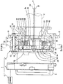
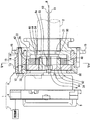
以下、本発明の一実施形態を図面に基づいて説明する。図1は、本発明の一実施形態によるバルブタイミング調整装置1を示している。バルブタイミング調整装置1は車両に搭載され、内燃機関のクランク軸(図示しない)からカム軸2へ機関トルクを伝達する伝達系に設置されている。尚、本実施形態においてカム軸2は、内燃機関の「動弁」のうち吸気弁(図示しない)を機関トルクの伝達によって開閉するものである。したがって、バルブタイミング調整装置1は、クランク軸に対するカム軸2の機関位相に応じたバルブタイミングを、吸気弁につき調整する。具体的にバルブタイミング調整装置1は、図1に示すように、アクチュエータ4、通電制御回路部7及び位相調整機構8等を組み合わせて構成されている。
Hereinafter, an embodiment of the present invention will be described with reference to the drawings. FIG. 1 shows a valve timing adjusting apparatus 1 according to an embodiment of the present invention. The valve timing adjusting device 1 is mounted on a vehicle and installed in a transmission system that transmits engine torque from a crankshaft (not shown) of an internal combustion engine to a camshaft 2. In the present embodiment, the camshaft 2 opens and closes an intake valve (not shown) of the “valve” of the internal combustion engine by transmitting engine torque. Therefore, the valve timing adjusting device 1 adjusts the valve timing corresponding to the engine phase of the camshaft 2 with respect to the crankshaft for each intake valve. Specifically, as shown in FIG. 1, the valve timing adjustment device 1 is configured by combining an
アクチュエータ4は、本実施形態ではブラシレスモータ等の電動モータからなり、内燃機関の固定節に固定されるケース5と、このケース5により正逆回転自在に支持される回転軸6とを、有している。通電制御回路部7は、駆動ドライバ及びその制御用マイクロコンピュータ等の電子回路から構成され、ケース5の外部及び/又は内部に配置されてアクチュエータ4と電気的に接続されている。通電制御回路部7は、バルブタイミングを内燃機関の運転状態に応じたタイミングに調整するための通電をアクチュエータ4に対して行うことにより、回転軸6の回転駆動を制御する。
The
位相調整機構8は、第一回転体10、第二回転体20、第一遊星歯車30、第二遊星歯車40、遊星キャリア50、弾性部材60及び連結部材70を備えている。金属製の第一回転体10は、全体として中空状に形成されており、位相調整機構8の他の構成要素20,30,40,50,60,70を内部に収容している。
The
図1〜3に示す第一回転体10は、歯車部材11及びスプロケット部材14の間に筒壁部材16を同軸上に共締めしてなる。有底円筒状を呈する歯車部材11は、歯底円の内周側に歯先円を有する第一内歯車部12を、周壁部に形成している。段付円筒状のスプロケット部材14は、周壁部から径方向外側へ突出する歯15を、回転方向に複数有している。スプロケット部材14は、それらの歯15とクランク軸の複数の歯との間でタイミングチェーン(図示しない)が掛け渡されることにより、クランク軸と連繋する。かかるスプロケット部材14とクランク軸との連繋により、クランク軸から出力される機関トルクがタイミングチェーンを通じてスプロケット部材14へ伝達されることで、第一回転体10がクランク軸と連動して回転する。したがって、第一回転体10の回転方向は、一定(図2,3の反時計方向)となる。
The first rotating
図1,3に示すように、有底円筒状を呈する金属製の第二回転体20は、それよりも大径円筒状の筒壁部材16内に同軸上に配置されている。第二回転体20は、カム軸2に同軸上に固定される固定部21を、底壁部に形成している。かかる固定部21の固定により第二回転体20は、カム軸2と連動して回転可能となっており、また第一回転体10に対して相対回転可能となっている。ここで第二回転体20の回転方向は、第一回転体10と同一方向(図3の反時計方向)となる。
As shown in FIGS. 1 and 3, the second
第二回転体20は、歯底円の内周側に歯先円を有する第二内歯車部22を、周壁部に形成している。第一内歯車部12に対して第二内歯車部22は、軸方向のカム軸2側にずれた状態で、同軸上に配置されている。第二内歯車部22の内径は第一内歯車部12の内径よりも小さく設定され、また第二内歯車部22の歯数は第一内歯車部12の歯数よりも少なく設定されている。
The 2nd
図1,2に示すように、円環板状を呈する金属製の第一遊星歯車30は、歯底円の外周側に歯先円を有する第一外歯車部32を、周壁部に形成している。第一外歯車部32は、内歯車部12,22に対して径方向に偏心して配置され、当該偏心側にて第一内歯車部12と噛合している。
As shown in FIGS. 1 and 2, the metal first
図1,3に示すように、円環板状を呈する金属製の第二遊星歯車40は、歯底円の外周側に歯先円を有する第二外歯車部42を、周壁部に形成している。第二外歯車部42は、第一外歯車部32に対して軸方向のカム軸2側にずれた状態で、内歯車部12,22に対しては径方向のうち当該第一外歯車部32と反対側に偏心して配置され、当該偏心側にて第二内歯車部22と噛合している。第二外歯車部42の外径は第一外歯車部32の外径よりも小さく設定され、またそれら第二外歯車部42及び第一外歯車部32の歯数は、それぞれ噛合する第二内歯車部22及び第一内歯車部12の歯数よりも同数ずつ、少なく設定されている。
As shown in FIGS. 1 and 3, the metal second
図1〜3に示すように、金属製の遊星キャリア50は、軸方向の全域において内周面51と外周面52とを同軸上に有する円筒状に、形成されている。遊星キャリア50は、内歯車部12,22に対して第一外歯車部32と同一側へ同一量だけ偏心して配置され、それら各内歯車部12,22と同軸上の回転軸6に対しても偏心している。即ち、これらの構成から遊星キャリア50の内外周面51,52は、内歯車部12,22及び回転軸6に対して偏心し且つ第一外歯車部32に対して同軸上の円筒面状を、呈している。
As shown in FIGS. 1 to 3, the
遊星キャリア50の内周面51に開口する一対の嵌合溝53は、回転軸6に設けられた継手部6aに対して、隙間をあけて嵌合する遊嵌状態で連係している。かかる嵌合溝53と継手部6aとの連係により遊星キャリア50は、アクチュエータ4によって回転軸6と共に回転駆動可能となっており、また内歯車部12,22に対して相対回転可能となっている。
The pair of
図1,2に示すように遊星キャリア50の外周面52は、アクチュエータ4側の軸方向端部を含む部分にて、第一遊星歯車30の中心孔34に同軸上に嵌合している。かかる中心孔34との嵌合により外周面52は、第一遊星歯車30を内周側から、遊星運動可能に支持している。ここで第一遊星歯車30の遊星運動とは、内歯車部12,22に対する第一外歯車部32及び外周面52の偏心軸線E1周りに自転しつつ、回転軸6の中心軸線と一致する遊星キャリア50の回転軸線R周りに公転する運動をいう。
As shown in FIGS. 1 and 2, the outer
図1,3に示すように、遊星キャリア50の外周面52のうちカム軸2側の軸方向端部を含む部分には、それぞれ弾性部材60を個別に保持する保持孔54が開口している。各弾性部材60は、断面が概ねV字状を呈する金属製の板ばねであり、対応する保持孔54と第二遊星歯車40の中心孔44との間に挟持されている。かかる弾性部材60を介することにより外周面52は、保持孔54の形成部分にて第二遊星歯車40を内周側から、遊星運動可能に支持している。ここで第二遊星歯車40の遊星運動とは、内歯車部12,22に対する第二外歯車部42の偏心軸線E2周りに自転しつつ、遊星キャリア50の回転軸線R周りに公転する運動をいう。
As shown in FIGS. 1 and 3, holding
各弾性部材60は、遊星キャリア50と第二遊星歯車40との間において弾性変形することにより、それぞれ復原力を発生する。ここで図3に示すように、各外歯車部32,42の偏心軸線E1,E2が含まれる仮想平面Pを挟んで対称位置に配置される本実施形態の各弾性部材60は、発生させた復原力の合力を、第二遊星歯車40及び遊星キャリア50の各々に対して径方向の相反側に作用させる。かかる復原力作用により、第二遊星歯車40は内歯車部12,22に対する第二外歯車部42の偏心側へ付勢される一方、遊星キャリア50は歯車40とは反対側へ、即ち内歯車部12,22に対する外周面52及び第一外歯車部32の偏心側へ付勢されることになる。
Each
図1〜3に示すように、細長の円柱棒状を呈する金属製の連結部材70は、各外歯車部32,42の偏心軸線E1,E2と共に遊星キャリア50の回転軸線Rを含む仮想平面P上に、一対設けられている。各連結部材70は、回転軸線Rを径方向に挟む両側、即ち第一外歯車部32の偏心側と第二外歯車部42の偏心側とに、配置されている。各連結部材70においてアクチュエータ4側の軸方向端部を含む部分は、第一遊星歯車30を貫通する一対の第一嵌合孔36のうち各々対応する一方に対して、軸方向に嵌合している。ここで本実施形態では、円筒孔状の各第一嵌合孔36に対して、各連結部材70が圧入状態で嵌合固定されている。一方、各連結部材70においてカム軸2側の軸方向端部を含む部分は、第二遊星歯車40を貫通する一対の第二嵌合孔46のうち各々対応する一方に対して、軸方向に嵌合している。ここで本実施形態では、仮想平面Pに沿って延びる長孔状の各第二嵌合孔46に対して、各連結部材70が第二遊星歯車40の径方向にスライド変位可能に嵌合されている。かかる各第二嵌合孔46への嵌合形態により各連結部材70は、第一外歯車部32と第二外歯車部42とを各々の偏心側へ相対変位可能に連結しているのである。
As shown in FIGS. 1 to 3, the
以上の構成により位相調整機構8は、遊星歯車30,40を主体とした遊星歯車機構を介して、回転体10,20間を連係する形となっている。このような位相調整機構8では、遊星キャリア50と共に回転軸6が遊星歯車30,40の公転方向へ回転駆動されることにより、機関位相が調整されて所望のバルブタイミングが得られることとなる。
With the above configuration, the
具体的には、回転軸6が第一回転体10と同速に回転駆動されるときには、遊星キャリア50が内歯車部12,22に対して相対回転しないので、遊星歯車30,40のいずれも遊星運動しない。その結果、遊星歯車30,40が遊星キャリア50及び回転体10,20と連れ回りするので、機関位相の変化が生じず、バルブタイミングが保持されることとなる。一方、回転軸6が第一回転体10よりも高速に回転駆動されるときには、遊星キャリア50が内歯車部12,22に対して進角側へ相対回転するので、遊星歯車30,40がそれぞれ遊星運動する。その結果、第一回転体10に対して第二回転体20が進角側へと相対回転するので、機関位相が進角側へ変化し、バルブタイミングが進角することとなる。また一方、回転軸6が第一回転体10よりも低速に回転駆動される又は第一回転体10とは反対方向に回転駆動されるときには、遊星キャリア50が内歯車部12,22に対して遅角側へ相対回転するので、遊星歯車30,40がそれぞれ遊星運動する。その結果、第一回転体10に対して第二回転体20が遅角側へと相対回転するので、機関位相が遅角側へ変化し、バルブタイミングが遅角することとなる。
Specifically, when the
ここまで説明したように装置1では、個別の回転体10,20に同軸上に形成される内歯車部12,22に対して、個別の遊星歯車30,40に形成される外歯車部32,42が、相反側へ偏心して各々の偏心側にて噛合する。ここで第二遊星歯車40は、遊星キャリア50の外周面52に保持される各弾性部材60により、第二外歯車部42の偏心側へと付勢されるので、かかる第二外歯車部42については、当該偏心側にて噛合する第二内歯車部22に押し付けられてバックラッシを消失させ得る。また、各弾性部材60により第一外歯車部32の偏心側へ付勢される遊星キャリア50において、外周面52が内周側から同軸支持する第一遊星歯車30の第一外歯車部32については、当該偏心側にて噛合する第一内歯車部12に押し付けられてバックラッシを消失させ得る。
As described so far, in the device 1, the
ここで、遊星歯車30,40に対して連結部材70が軸方向に嵌合して外歯車部32,42間を連結している装置1では、それら外歯車部32,42の相反側への偏心形態が確実に維持され得る。また、そうした偏心形態の外歯車部32,42については、各弾性部材60の付勢作用を受けることにより各々の偏心側へと相対変位して、各別の内歯車部12,22との噛合状態も維持され得るので、上述の如きバックラッシの消失作用は確実なものとなる。しかも、相異なる遊星歯車30,40に形成されて同軸度の不要な偏心形態の外歯車部32,42については、装置1の組立時に各々の偏心側へと相対変位させながら、各別の内歯車部12,22との噛合具合を同時に調整し得る。故に、各歯車部32,42,12,22の輪郭度や内歯車部12,22同士の同軸度に対して、要求精度を低下させることが可能になる。
Here, in the device 1 in which the connecting
以上によれば、バックラッシの消失による異音の発生抑制効果と、要求精度の低下による生産性の向上効果とを、両立して発揮できるのである。さらに装置1では、軸方向の全域にて外周面52を内周面51と同軸上に有する円筒状の遊星キャリア50につき、その簡素な形状に応じて加工精度の低下を図り得るので、生産性の向上に貢献できる。加えて装置1では、簡素形状の遊星キャリア50のうち内周面51に対して、内歯車部12,22と同軸上の回転軸6が偏心状態で遊嵌されることにより、それら回転軸6及び遊星キャリア50の公転方向への回転駆動が可能となっている。このような装置1によれば、遊星キャリア50の加工精度だけでなく、遊星キャリア50の回転駆動に必要な回転軸6の配置精度も低下させ得るので、これによっても、生産性の向上に貢献できるのである。
According to the above, it is possible to achieve both the effect of suppressing the generation of abnormal noise due to the disappearance of backlash and the effect of improving productivity due to a decrease in required accuracy. Furthermore, in the apparatus 1, the processing accuracy of the cylindrical
(他の実施形態)
以上、本発明の一実施形態について説明したが、本発明は、当該実施形態に限定して解釈されるものではなく、本発明の要旨を逸脱しない範囲内において種々の実施形態に適用することができる。
(Other embodiments)
Although one embodiment of the present invention has been described above, the present invention is not construed as being limited to the embodiment, and can be applied to various embodiments without departing from the gist of the present invention. it can.
具体的に連結部材70については、第二遊星歯車40に圧入状態で嵌合固定し且つ第一遊星歯車30にスライド移動可能に嵌合させてもよいし、遊星歯車30,40の双方にスライド移動可能に嵌合させてもよい。また、図4,5に示すように連結部材70を設けずに、弾性部材60の付勢作用のみにより外歯車部32,42の相反側への偏心形態を維持する構成としてもよい。さらに弾性部材60の配設数については、適宜設定可能であり、例えば図5に示すように、唯一の弾性部材60が発生する復原力により第二遊星歯車40と遊星キャリア50とを、それぞれ第二外歯車部42の偏心側と外周面52(第一外歯車部32)の偏心側とへ付勢する構成としてもよい。
Specifically, the connecting
加えて、回転体10をカム軸2と連動回転させ、回転体20をクランク軸と連動回転させてもよい。また加えて、内歯車部12,22に対して外歯車部42と同一側へ偏心する遊星キャリア50の外周面52により遊星歯車40を内周側から支持し、且つ遊星歯車30を外歯車部32の偏心側へ付勢する弾性部材60を同外周面52により保持する構成としてもよい(この場合、上述の実施形態の説明において「第一」を「第二」として、また逆に「第二」を「第一」として読み替えることにより、特許請求の範囲に記載の発明に対応する実施形態として、考えることができる)。
In addition, the rotating
さらに加えて、回転軸6と共に遊星キャリア50を回転駆動するアクチュエータ4としては、電動モータ以外の例えば電動ブレーキ等を採用してもよい。そして、本発明は、吸気弁のバルブタイミングを調整する装置以外にも、「動弁」としての排気弁のバルブタイミングを調整する装置や、吸気弁及び排気弁の双方のバルブタイミングを調整する装置に適用できるのである。
In addition, as the
1 バルブタイミング調整装置、2 カム軸、4 アクチュエータ、6 回転軸、6a 継手部、7 通電制御回路部、8 位相調整機構、10 第一回転体、11 歯車部材、12 第一内歯車部、14 スプロケット部材、20 第二回転体、22 第二内歯車部、30 第一遊星歯車、32 第一外歯車部、34 中心孔、36 第一嵌合孔、40 第二遊星歯車、42 第二外歯車部、44 中心孔、46 第二嵌合孔、50 遊星キャリア、51 内周面、52 外周面、53 嵌合溝、54 保持孔、60 弾性部材、70 連結部材、E1,E2 偏心軸線、P 仮想平面、R 回転軸線 DESCRIPTION OF SYMBOLS 1 Valve timing adjustment apparatus, 2 Cam shaft, 4 Actuator, 6 Rotating shaft, 6a Joint part, 7 Current supply control circuit part, 8 Phase adjustment mechanism, 10 1st rotary body, 11 Gear member, 12 1st internal gear part, 14 Sprocket member, 20 second rotating body, 22 second inner gear portion, 30 first planetary gear, 32 first outer gear portion, 34 center hole, 36 first fitting hole, 40 second planetary gear, 42 second outer Gear part, 44 Center hole, 46 Second fitting hole, 50 Planetary carrier, 51 Inner peripheral surface, 52 Outer peripheral surface, 53 Fitting groove, 54 Holding hole, 60 Elastic member, 70 Connecting member, E1, E2 Eccentric axis, P virtual plane, R rotation axis
Claims (4)
第一内歯車部を形成し、前記クランク軸及び前記カム軸のうち一方と連動して回転する第一回転体と、
前記第一内歯車部に対して同軸上に第二内歯車部を形成し、前記クランク軸及び前記カム軸のうち他方と連動して回転する第二回転体と、
前記第一内歯車部及び前記第二内歯車部に対して偏心する第一外歯車部を形成し、この第一外歯車部が偏心側において前記第一内歯車部と噛合しつつ遊星運動する第一遊星歯車と、
前記第一内歯車部及び前記第二内歯車部に対して前記第一外歯車部とは反対側へ偏心する第二外歯車部を形成し、この第二外歯車部が偏心側において前記第二内歯車部と噛合しつつ遊星運動する第二遊星歯車と、
前記第一内歯車部及び前記第二内歯車部に対して前記第一外歯車部と同一側へ偏心する外周面を有し、この外周面により前記第一遊星歯車を内周側から同軸上に支持する遊星キャリアと、
前記第二遊星歯車の内周側において前記外周面により保持され、前記第二遊星歯車を前記第二外歯車部の偏心側へ付勢し且つ前記遊星キャリアを前記外周面の偏心側へ付勢する弾性部材とを、
備え、前記第一遊星歯車及び前記第二遊星歯車の公転方向へ前記遊星キャリアが回転するのに伴って、前記第一遊星歯車及び前記第二遊星歯車が遊星運動することにより、前記クランク軸及び前記カム軸の間の回転位相が変化することを特徴とするバルブタイミング調整装置。 A valve timing adjusting device for adjusting a valve timing of a valve that opens and closes a camshaft by torque transmission from a crankshaft in an internal combustion engine,
A first rotating body that forms a first internal gear portion and rotates in conjunction with one of the crankshaft and the camshaft;
Forming a second internal gear portion coaxially with the first internal gear portion, and a second rotating body that rotates in conjunction with the other of the crankshaft and the camshaft;
A first external gear portion that is eccentric with respect to the first internal gear portion and the second internal gear portion is formed, and the first external gear portion makes a planetary movement while meshing with the first internal gear portion on the eccentric side. The first planetary gear,
A second external gear portion that is eccentric to the first internal gear portion and the second internal gear portion opposite to the first external gear portion is formed, and the second external gear portion is formed on the eccentric side on the first side. A second planetary gear that planetarily moves while meshing with the two internal gears;
The first internal gear portion and the second internal gear portion have an outer peripheral surface that is eccentric to the same side as the first external gear portion, and the outer peripheral surface allows the first planetary gear to be coaxial from the inner peripheral side. Planetary carrier that supports
The second planetary gear is held by the outer peripheral surface on the inner peripheral side, biases the second planetary gear toward the eccentric side of the second outer gear portion, and biases the planet carrier toward the eccentric side of the outer peripheral surface. An elastic member to be
The first planetary gear and the second planetary gear make a planetary motion as the planetary carrier rotates in the revolving direction of the first planetary gear and the second planetary gear, and the crankshaft and The valve timing adjusting device characterized in that a rotational phase between the cam shafts changes.
備えることを特徴とする請求項1又は2に記載のバルブタイミング調整装置。 The planetary carrier having a rotation shaft coaxially with respect to the first internal gear portion and the second internal gear portion and having the rotation shaft eccentric with respect to the inner peripheral surface is loosely fitted to the rotation shaft. Together with an actuator for rotationally driving in the revolving direction,
The valve timing adjusting device according to claim 1, comprising: a valve timing adjusting device according to claim 1.
備えることを特徴とする請求項1〜3のいずれか一項に記載のバルブタイミング調整装置。 A coupling member that couples the first external gear part and the second external gear part to each eccentric side so as to be relatively displaceable by axially fitting to the first planetary gear and the second planetary gear,
The valve timing adjusting device according to any one of claims 1 to 3, wherein the valve timing adjusting device is provided.
Priority Applications (1)
| Application Number | Priority Date | Filing Date | Title |
|---|---|---|---|
| JP2011055561A JP2012189050A (en) | 2011-03-14 | 2011-03-14 | Valve timing adjustment device |
Applications Claiming Priority (1)
| Application Number | Priority Date | Filing Date | Title |
|---|---|---|---|
| JP2011055561A JP2012189050A (en) | 2011-03-14 | 2011-03-14 | Valve timing adjustment device |
Publications (1)
| Publication Number | Publication Date |
|---|---|
| JP2012189050A true JP2012189050A (en) | 2012-10-04 |
Family
ID=47082474
Family Applications (1)
| Application Number | Title | Priority Date | Filing Date |
|---|---|---|---|
| JP2011055561A Withdrawn JP2012189050A (en) | 2011-03-14 | 2011-03-14 | Valve timing adjustment device |
Country Status (1)
| Country | Link |
|---|---|
| JP (1) | JP2012189050A (en) |
Cited By (6)
| Publication number | Priority date | Publication date | Assignee | Title |
|---|---|---|---|---|
| EP3179063A1 (en) * | 2015-12-09 | 2017-06-14 | Hyundai Motor Company | Valve timing control apparatus of internal combustion engine |
| WO2017153275A1 (en) * | 2016-03-09 | 2017-09-14 | Pierburg Gmbh | Eccentric and device for phase shifting a rotational angle of a drive part relative to a driven part |
| EP3296529A1 (en) * | 2016-09-15 | 2018-03-21 | Aisin Seiki Kabushiki Kaisha | Valve opening and closing timing control apparatus |
| EP3296530A1 (en) | 2016-09-15 | 2018-03-21 | Aisin Seiki Kabushiki Kaisha | Valve opening and closing timing control apparatus |
| EP3767084A1 (en) | 2019-07-18 | 2021-01-20 | Aisin Seiki Kabushiki Kaisha | Valve opening-closing timing control apparatus |
| US11242775B2 (en) | 2019-09-20 | 2022-02-08 | Denso Corporation | Valve timing adjustment device |
-
2011
- 2011-03-14 JP JP2011055561A patent/JP2012189050A/en not_active Withdrawn
Cited By (17)
| Publication number | Priority date | Publication date | Assignee | Title |
|---|---|---|---|---|
| US10107155B2 (en) | 2015-12-09 | 2018-10-23 | Hyundai Motor Company | Valve timing control apparatus of internal combustion engine |
| JP2017106468A (en) * | 2015-12-09 | 2017-06-15 | 現代自動車株式会社Hyundai Motor Company | Valve timing control device for internal combustion engine |
| CN106988820A (en) * | 2015-12-09 | 2017-07-28 | 现代自动车株式会社 | The Ventilsteuerzeitsteuervorrichtung of internal combustion engine |
| EP3179063A1 (en) * | 2015-12-09 | 2017-06-14 | Hyundai Motor Company | Valve timing control apparatus of internal combustion engine |
| CN106988820B (en) * | 2015-12-09 | 2021-03-26 | 现代自动车株式会社 | Valve timing control device for internal combustion engine |
| WO2017153275A1 (en) * | 2016-03-09 | 2017-09-14 | Pierburg Gmbh | Eccentric and device for phase shifting a rotational angle of a drive part relative to a driven part |
| EP3296529A1 (en) * | 2016-09-15 | 2018-03-21 | Aisin Seiki Kabushiki Kaisha | Valve opening and closing timing control apparatus |
| JP2018044500A (en) * | 2016-09-15 | 2018-03-22 | アイシン精機株式会社 | Valve opening/closing timing control device |
| JP2018044501A (en) * | 2016-09-15 | 2018-03-22 | アイシン精機株式会社 | Valve opening/closing timing control device |
| US10385985B2 (en) | 2016-09-15 | 2019-08-20 | Aisin Seiki Kabushiki Kaisha | Valve opening and closing timing control apparatus |
| US10514109B2 (en) | 2016-09-15 | 2019-12-24 | Aisin Seiki Kabushiki Kaisha | Valve opening and closing timing control apparatus |
| EP3296530A1 (en) | 2016-09-15 | 2018-03-21 | Aisin Seiki Kabushiki Kaisha | Valve opening and closing timing control apparatus |
| EP3767084A1 (en) | 2019-07-18 | 2021-01-20 | Aisin Seiki Kabushiki Kaisha | Valve opening-closing timing control apparatus |
| JP2021017833A (en) * | 2019-07-18 | 2021-02-15 | アイシン精機株式会社 | Valve opening/closing timing controller |
| US11143062B2 (en) | 2019-07-18 | 2021-10-12 | Aisin Corporation | Valve opening-closing timing control apparatus |
| JP7400236B2 (en) | 2019-07-18 | 2023-12-19 | 株式会社アイシン | Valve opening/closing timing control device |
| US11242775B2 (en) | 2019-09-20 | 2022-02-08 | Denso Corporation | Valve timing adjustment device |
Similar Documents
| Publication | Publication Date | Title |
|---|---|---|
| JP4390078B2 (en) | Valve timing adjustment device | |
| JP4360426B2 (en) | Valve timing adjustment device | |
| WO2016031557A1 (en) | Valve opening/closing timing control device | |
| JP4735720B2 (en) | Valve timing adjustment device | |
| JP2012189050A (en) | Valve timing adjustment device | |
| JP2018044500A (en) | Valve opening/closing timing control device | |
| JP2013503287A (en) | Valve actuator with variable cam phaser | |
| JP6443382B2 (en) | Valve timing adjustment device | |
| JP2009185785A (en) | Valve timing adjusting device | |
| JP5494547B2 (en) | Valve timing adjustment device | |
| JP6102846B2 (en) | Valve timing adjustment device | |
| JP4760953B2 (en) | Valve timing adjustment device | |
| JP2009215954A (en) | Valve timing adjusting device | |
| JP4419092B2 (en) | Valve timing adjustment device | |
| JP4978627B2 (en) | Valve timing adjustment device | |
| JP2008095552A (en) | Valve-timing adjuster | |
| JP6228065B2 (en) | Valve timing adjustment device | |
| JP2008215314A (en) | Valve timing adjusting device | |
| JP2007297924A (en) | Valve timing adjusting device | |
| JP5240309B2 (en) | Valve timing adjustment device | |
| JP7131445B2 (en) | valve timing adjuster | |
| JP2015102065A (en) | Valve opening/closing timing control device | |
| JP2021046844A (en) | Valve timing adjustment device | |
| JP5920096B2 (en) | Valve timing adjustment device | |
| JP2013083171A (en) | Valve timing control device |
Legal Events
| Date | Code | Title | Description |
|---|---|---|---|
| A300 | Withdrawal of application because of no request for examination |
Free format text: JAPANESE INTERMEDIATE CODE: A300 Effective date: 20140603 |