EP3296277A1 - Insulated glass unit for vehicles, and production method therefor - Google Patents
Insulated glass unit for vehicles, and production method therefor Download PDFInfo
- Publication number
- EP3296277A1 EP3296277A1 EP16792465.3A EP16792465A EP3296277A1 EP 3296277 A1 EP3296277 A1 EP 3296277A1 EP 16792465 A EP16792465 A EP 16792465A EP 3296277 A1 EP3296277 A1 EP 3296277A1
- Authority
- EP
- European Patent Office
- Prior art keywords
- layer
- heat insulating
- glass
- glass unit
- insulating glass
- Prior art date
- Legal status (The legal status is an assumption and is not a legal conclusion. Google has not performed a legal analysis and makes no representation as to the accuracy of the status listed.)
- Granted
Links
Images

Classifications
-
- C—CHEMISTRY; METALLURGY
- C03—GLASS; MINERAL OR SLAG WOOL
- C03C—CHEMICAL COMPOSITION OF GLASSES, GLAZES OR VITREOUS ENAMELS; SURFACE TREATMENT OF GLASS; SURFACE TREATMENT OF FIBRES OR FILAMENTS MADE FROM GLASS, MINERALS OR SLAGS; JOINING GLASS TO GLASS OR OTHER MATERIALS
- C03C17/00—Surface treatment of glass, not in the form of fibres or filaments, by coating
- C03C17/34—Surface treatment of glass, not in the form of fibres or filaments, by coating with at least two coatings having different compositions
- C03C17/36—Surface treatment of glass, not in the form of fibres or filaments, by coating with at least two coatings having different compositions at least one coating being a metal
-
- B—PERFORMING OPERATIONS; TRANSPORTING
- B32—LAYERED PRODUCTS
- B32B—LAYERED PRODUCTS, i.e. PRODUCTS BUILT-UP OF STRATA OF FLAT OR NON-FLAT, e.g. CELLULAR OR HONEYCOMB, FORM
- B32B17/00—Layered products essentially comprising sheet glass, or glass, slag, or like fibres
- B32B17/06—Layered products essentially comprising sheet glass, or glass, slag, or like fibres comprising glass as the main or only constituent of a layer, next to another layer of a specific material
- B32B17/10—Layered products essentially comprising sheet glass, or glass, slag, or like fibres comprising glass as the main or only constituent of a layer, next to another layer of a specific material of synthetic resin
- B32B17/10005—Layered products essentially comprising sheet glass, or glass, slag, or like fibres comprising glass as the main or only constituent of a layer, next to another layer of a specific material of synthetic resin laminated safety glass or glazing
- B32B17/10009—Layered products essentially comprising sheet glass, or glass, slag, or like fibres comprising glass as the main or only constituent of a layer, next to another layer of a specific material of synthetic resin laminated safety glass or glazing characterized by the number, the constitution or treatment of glass sheets
- B32B17/10036—Layered products essentially comprising sheet glass, or glass, slag, or like fibres comprising glass as the main or only constituent of a layer, next to another layer of a specific material of synthetic resin laminated safety glass or glazing characterized by the number, the constitution or treatment of glass sheets comprising two outer glass sheets
-
- B—PERFORMING OPERATIONS; TRANSPORTING
- B32—LAYERED PRODUCTS
- B32B—LAYERED PRODUCTS, i.e. PRODUCTS BUILT-UP OF STRATA OF FLAT OR NON-FLAT, e.g. CELLULAR OR HONEYCOMB, FORM
- B32B17/00—Layered products essentially comprising sheet glass, or glass, slag, or like fibres
- B32B17/06—Layered products essentially comprising sheet glass, or glass, slag, or like fibres comprising glass as the main or only constituent of a layer, next to another layer of a specific material
- B32B17/10—Layered products essentially comprising sheet glass, or glass, slag, or like fibres comprising glass as the main or only constituent of a layer, next to another layer of a specific material of synthetic resin
- B32B17/10005—Layered products essentially comprising sheet glass, or glass, slag, or like fibres comprising glass as the main or only constituent of a layer, next to another layer of a specific material of synthetic resin laminated safety glass or glazing
- B32B17/10165—Functional features of the laminated safety glass or glazing
- B32B17/10174—Coatings of a metallic or dielectric material on a constituent layer of glass or polymer
- B32B17/10201—Dielectric coatings
-
- B—PERFORMING OPERATIONS; TRANSPORTING
- B32—LAYERED PRODUCTS
- B32B—LAYERED PRODUCTS, i.e. PRODUCTS BUILT-UP OF STRATA OF FLAT OR NON-FLAT, e.g. CELLULAR OR HONEYCOMB, FORM
- B32B9/00—Layered products comprising a layer of a particular substance not covered by groups B32B11/00 - B32B29/00
- B32B9/04—Layered products comprising a layer of a particular substance not covered by groups B32B11/00 - B32B29/00 comprising such particular substance as the main or only constituent of a layer, which is next to another layer of the same or of a different material
- B32B9/045—Layered products comprising a layer of a particular substance not covered by groups B32B11/00 - B32B29/00 comprising such particular substance as the main or only constituent of a layer, which is next to another layer of the same or of a different material of synthetic resin
-
- B—PERFORMING OPERATIONS; TRANSPORTING
- B60—VEHICLES IN GENERAL
- B60J—WINDOWS, WINDSCREENS, NON-FIXED ROOFS, DOORS, OR SIMILAR DEVICES FOR VEHICLES; REMOVABLE EXTERNAL PROTECTIVE COVERINGS SPECIALLY ADAPTED FOR VEHICLES
- B60J1/00—Windows; Windscreens; Accessories therefor
-
- C—CHEMISTRY; METALLURGY
- C03—GLASS; MINERAL OR SLAG WOOL
- C03C—CHEMICAL COMPOSITION OF GLASSES, GLAZES OR VITREOUS ENAMELS; SURFACE TREATMENT OF GLASS; SURFACE TREATMENT OF FIBRES OR FILAMENTS MADE FROM GLASS, MINERALS OR SLAGS; JOINING GLASS TO GLASS OR OTHER MATERIALS
- C03C17/00—Surface treatment of glass, not in the form of fibres or filaments, by coating
- C03C17/22—Surface treatment of glass, not in the form of fibres or filaments, by coating with other inorganic material
- C03C17/23—Oxides
- C03C17/245—Oxides by deposition from the vapour phase
- C03C17/2453—Coating containing SnO2
-
- C—CHEMISTRY; METALLURGY
- C03—GLASS; MINERAL OR SLAG WOOL
- C03C—CHEMICAL COMPOSITION OF GLASSES, GLAZES OR VITREOUS ENAMELS; SURFACE TREATMENT OF GLASS; SURFACE TREATMENT OF FIBRES OR FILAMENTS MADE FROM GLASS, MINERALS OR SLAGS; JOINING GLASS TO GLASS OR OTHER MATERIALS
- C03C17/00—Surface treatment of glass, not in the form of fibres or filaments, by coating
- C03C17/22—Surface treatment of glass, not in the form of fibres or filaments, by coating with other inorganic material
- C03C17/23—Oxides
- C03C17/245—Oxides by deposition from the vapour phase
- C03C17/2456—Coating containing TiO2
-
- C—CHEMISTRY; METALLURGY
- C03—GLASS; MINERAL OR SLAG WOOL
- C03C—CHEMICAL COMPOSITION OF GLASSES, GLAZES OR VITREOUS ENAMELS; SURFACE TREATMENT OF GLASS; SURFACE TREATMENT OF FIBRES OR FILAMENTS MADE FROM GLASS, MINERALS OR SLAGS; JOINING GLASS TO GLASS OR OTHER MATERIALS
- C03C17/00—Surface treatment of glass, not in the form of fibres or filaments, by coating
- C03C17/22—Surface treatment of glass, not in the form of fibres or filaments, by coating with other inorganic material
- C03C17/23—Oxides
- C03C17/25—Oxides by deposition from the liquid phase
- C03C17/256—Coating containing TiO2
-
- C—CHEMISTRY; METALLURGY
- C03—GLASS; MINERAL OR SLAG WOOL
- C03C—CHEMICAL COMPOSITION OF GLASSES, GLAZES OR VITREOUS ENAMELS; SURFACE TREATMENT OF GLASS; SURFACE TREATMENT OF FIBRES OR FILAMENTS MADE FROM GLASS, MINERALS OR SLAGS; JOINING GLASS TO GLASS OR OTHER MATERIALS
- C03C17/00—Surface treatment of glass, not in the form of fibres or filaments, by coating
- C03C17/34—Surface treatment of glass, not in the form of fibres or filaments, by coating with at least two coatings having different compositions
- C03C17/3411—Surface treatment of glass, not in the form of fibres or filaments, by coating with at least two coatings having different compositions with at least two coatings of inorganic materials
- C03C17/3417—Surface treatment of glass, not in the form of fibres or filaments, by coating with at least two coatings having different compositions with at least two coatings of inorganic materials all coatings being oxide coatings
-
- C—CHEMISTRY; METALLURGY
- C03—GLASS; MINERAL OR SLAG WOOL
- C03C—CHEMICAL COMPOSITION OF GLASSES, GLAZES OR VITREOUS ENAMELS; SURFACE TREATMENT OF GLASS; SURFACE TREATMENT OF FIBRES OR FILAMENTS MADE FROM GLASS, MINERALS OR SLAGS; JOINING GLASS TO GLASS OR OTHER MATERIALS
- C03C17/00—Surface treatment of glass, not in the form of fibres or filaments, by coating
- C03C17/34—Surface treatment of glass, not in the form of fibres or filaments, by coating with at least two coatings having different compositions
- C03C17/3411—Surface treatment of glass, not in the form of fibres or filaments, by coating with at least two coatings having different compositions with at least two coatings of inorganic materials
- C03C17/3429—Surface treatment of glass, not in the form of fibres or filaments, by coating with at least two coatings having different compositions with at least two coatings of inorganic materials at least one of the coatings being a non-oxide coating
- C03C17/3435—Surface treatment of glass, not in the form of fibres or filaments, by coating with at least two coatings having different compositions with at least two coatings of inorganic materials at least one of the coatings being a non-oxide coating comprising a nitride, oxynitride, boronitride or carbonitride
-
- C—CHEMISTRY; METALLURGY
- C03—GLASS; MINERAL OR SLAG WOOL
- C03C—CHEMICAL COMPOSITION OF GLASSES, GLAZES OR VITREOUS ENAMELS; SURFACE TREATMENT OF GLASS; SURFACE TREATMENT OF FIBRES OR FILAMENTS MADE FROM GLASS, MINERALS OR SLAGS; JOINING GLASS TO GLASS OR OTHER MATERIALS
- C03C17/00—Surface treatment of glass, not in the form of fibres or filaments, by coating
- C03C17/34—Surface treatment of glass, not in the form of fibres or filaments, by coating with at least two coatings having different compositions
- C03C17/36—Surface treatment of glass, not in the form of fibres or filaments, by coating with at least two coatings having different compositions at least one coating being a metal
- C03C17/3602—Surface treatment of glass, not in the form of fibres or filaments, by coating with at least two coatings having different compositions at least one coating being a metal the metal being present as a layer
- C03C17/3618—Coatings of type glass/inorganic compound/other inorganic layers, at least one layer being metallic
-
- C—CHEMISTRY; METALLURGY
- C03—GLASS; MINERAL OR SLAG WOOL
- C03C—CHEMICAL COMPOSITION OF GLASSES, GLAZES OR VITREOUS ENAMELS; SURFACE TREATMENT OF GLASS; SURFACE TREATMENT OF FIBRES OR FILAMENTS MADE FROM GLASS, MINERALS OR SLAGS; JOINING GLASS TO GLASS OR OTHER MATERIALS
- C03C17/00—Surface treatment of glass, not in the form of fibres or filaments, by coating
- C03C17/34—Surface treatment of glass, not in the form of fibres or filaments, by coating with at least two coatings having different compositions
- C03C17/36—Surface treatment of glass, not in the form of fibres or filaments, by coating with at least two coatings having different compositions at least one coating being a metal
- C03C17/3602—Surface treatment of glass, not in the form of fibres or filaments, by coating with at least two coatings having different compositions at least one coating being a metal the metal being present as a layer
- C03C17/3655—Surface treatment of glass, not in the form of fibres or filaments, by coating with at least two coatings having different compositions at least one coating being a metal the metal being present as a layer the multilayer coating containing at least one conducting layer
-
- C—CHEMISTRY; METALLURGY
- C03—GLASS; MINERAL OR SLAG WOOL
- C03C—CHEMICAL COMPOSITION OF GLASSES, GLAZES OR VITREOUS ENAMELS; SURFACE TREATMENT OF GLASS; SURFACE TREATMENT OF FIBRES OR FILAMENTS MADE FROM GLASS, MINERALS OR SLAGS; JOINING GLASS TO GLASS OR OTHER MATERIALS
- C03C17/00—Surface treatment of glass, not in the form of fibres or filaments, by coating
- C03C17/34—Surface treatment of glass, not in the form of fibres or filaments, by coating with at least two coatings having different compositions
- C03C17/36—Surface treatment of glass, not in the form of fibres or filaments, by coating with at least two coatings having different compositions at least one coating being a metal
- C03C17/3602—Surface treatment of glass, not in the form of fibres or filaments, by coating with at least two coatings having different compositions at least one coating being a metal the metal being present as a layer
- C03C17/3681—Surface treatment of glass, not in the form of fibres or filaments, by coating with at least two coatings having different compositions at least one coating being a metal the metal being present as a layer the multilayer coating being used in glazing, e.g. windows or windscreens
-
- C—CHEMISTRY; METALLURGY
- C03—GLASS; MINERAL OR SLAG WOOL
- C03C—CHEMICAL COMPOSITION OF GLASSES, GLAZES OR VITREOUS ENAMELS; SURFACE TREATMENT OF GLASS; SURFACE TREATMENT OF FIBRES OR FILAMENTS MADE FROM GLASS, MINERALS OR SLAGS; JOINING GLASS TO GLASS OR OTHER MATERIALS
- C03C27/00—Joining pieces of glass to pieces of other inorganic material; Joining glass to glass other than by fusing
- C03C27/06—Joining glass to glass by processes other than fusing
- C03C27/10—Joining glass to glass by processes other than fusing with the aid of adhesive specially adapted for that purpose
-
- E—FIXED CONSTRUCTIONS
- E06—DOORS, WINDOWS, SHUTTERS, OR ROLLER BLINDS IN GENERAL; LADDERS
- E06B—FIXED OR MOVABLE CLOSURES FOR OPENINGS IN BUILDINGS, VEHICLES, FENCES OR LIKE ENCLOSURES IN GENERAL, e.g. DOORS, WINDOWS, BLINDS, GATES
- E06B3/00—Window sashes, door leaves, or like elements for closing wall or like openings; Layout of fixed or moving closures, e.g. windows in wall or like openings; Features of rigidly-mounted outer frames relating to the mounting of wing frames
- E06B3/66—Units comprising two or more parallel glass or like panes permanently secured together
-
- B—PERFORMING OPERATIONS; TRANSPORTING
- B60—VEHICLES IN GENERAL
- B60J—WINDOWS, WINDSCREENS, NON-FIXED ROOFS, DOORS, OR SIMILAR DEVICES FOR VEHICLES; REMOVABLE EXTERNAL PROTECTIVE COVERINGS SPECIALLY ADAPTED FOR VEHICLES
- B60J1/00—Windows; Windscreens; Accessories therefor
- B60J1/02—Windows; Windscreens; Accessories therefor arranged at the vehicle front, e.g. structure of the glazing, mounting of the glazing
-
- C—CHEMISTRY; METALLURGY
- C03—GLASS; MINERAL OR SLAG WOOL
- C03C—CHEMICAL COMPOSITION OF GLASSES, GLAZES OR VITREOUS ENAMELS; SURFACE TREATMENT OF GLASS; SURFACE TREATMENT OF FIBRES OR FILAMENTS MADE FROM GLASS, MINERALS OR SLAGS; JOINING GLASS TO GLASS OR OTHER MATERIALS
- C03C2217/00—Coatings on glass
- C03C2217/90—Other aspects of coatings
- C03C2217/94—Transparent conductive oxide layers [TCO] being part of a multilayer coating
- C03C2217/948—Layers comprising indium tin oxide [ITO]
Definitions
- the disclosure herein generally relates to a heat insulating glass unit for vehicle and a manufacturing method thereof.
- Patent Document 1 discloses a heat insulating glass manufactured by forming a multilayered film configured with an indium tin oxide (ITO) and a silicon oxide (SiO 2 ) layer on a glass substrate.
- ITO indium tin oxide
- SiO 2 silicon oxide
- the heat insulating glass disclosed in Patent Document 1 has a feature that a visible light transmittance is high and the heat insulating performance is excellent.
- the above-described heat insulating glass has a problem such that color characteristics as viewed exhibit angle dependence. That is, the above-described heat insulating glass has a tendency that a color of a reflected light (reflection color) varies by a viewing direction. For example, when the heat insulating glass is viewed from a first direction, the heat insulating glass appears blue, but when the heat insulating glass is viewed from a second direction, the heat insulating glass appears yellow. Because the above-described angle dependence of reflection color for the heat insulating glass creates a strange impression to a user who views the heat insulating glass, it is preferable to control the angle dependence as much as possible.
- a plate (glass plate) disclosed in Patent Document 2 includes a heat radiation and reflection coating, has transparency and corrosion resistance, and has a feature of not being damaged upon a bending process.
- a barrier layer e.g. silicon nitride
- a thickness of 10 nm or more is required to be arranged.
- the visible light transmittance decreases when the barrier layer becomes thicker.
- the visible light transmittance required in the case of using the plate for a windshield of a car or the like e.g. a visible light transmittance T v of 72% or more
- productivity deteriorates.
- the present invention was made in view of such a problem, and it is an object of the present invention to provide a heat insulating glass unit in which the angle dependence of reflection color is improved. Moreover, the present invention aims at providing a manufacturing method of such a heat insulating glass unit.
- the present invention provides a heat insulating glass unit for vehicle including a laminated glass in which a first glass plate and a second glass plate are bonded to each other via an intermediate film; a color tone compensation film arranged on at least one surface of the laminated glass; a transparent conductive layer mainly including an indium tin oxide (ITO) arranged on the color tone compensation film; and an upper part layer arranged on the transparent conductive layer, a refraction index of the upper part layer for a light with a wavelength of 630 nm being 1.7 or less, the color tone compensation film having at least a first layer and a second layer, the first layer being arranged at a position closer to the laminated glass than the second layer, and a refraction index of the first layer for a light with a wavelength of 630 nm being greater than a refraction index of the second layer for a light with a wavelength of 630 nm.
- ITO indium tin oxide
- the present invention provides a manufacturing method of a heat insulating glass unit for vehicle including
- a heat insulating glass unit in which angle dependence of reflection color is rectified can be provided.
- a manufacturing method of such a heat insulating glass unit can be provided.
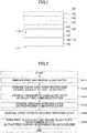
- FIG. 1 schematically illustrates a cross section of a heat insulating glass unit for vehicle according to an embodiment of the present invention.
- the heat insulating glass unit 100 includes a laminated glass 110, a color tone compensation film 130, a transparent conductive layer 140, an adhesion improving layer 150, and an upper part layer 160.
- the laminated glass 110 includes a first surface 112 and a second surface 114. Each layer (film), which will be described later, is arranged on the first surface 112 side.
- the laminated glass 110 is configured by bonding a first glass plate 115 and a second glass plate 125 via an intermediate film 120. Therefore, the first surface 112 of the laminated glass 110 corresponds to the outer surface of the first glass plate 115, and the second surface 114 of the laminated glass 110 corresponds to the outer surface of the second glass plate 125.
- the color tone compensation film 130 is arranged on the first surface 112 of the laminated glass 110.
- the color tone compensation film 130 has a role of adjusting angle dependence of reflection color of the heat insulating glass unit for vehicle 100 by controlling refraction indices of two or more layers included in the color tone compensation film 130.
- the color tone compensation film 130 is configured with two layers, i.e. a first layer 132 and a second layer 136.
- a refraction index of the first layer 132 for a light with a wavelength of 630 nm is higher than a refraction index of the second layer 136 for a light with a wavelength of 630 nm.
- the color tone compensation film 130 may be configured with three layers of more.
- the transparent conductive layer 140 is arranged above the color tone compensation film 130.
- the transparent conductive layer 140 is configured with a material mainly including an indium tin oxide (ITO).
- ITO indium tin oxide
- the phrase "layer 'A' mainly includes material 'B'” means that a layer 'A' includes a material 'B' of 50 mass% or more.
- the refraction index of the transparent conductive layer 140 for a light with a wavelength of 630 nm falls, for example, within a range of 1.7 to 1.8.
- the adhesion improving layer 150 is arranged between the transparent conductive layer 140 and the upper part layer 160, and has a role of suppressing an exfoliation at an interface between both layers.
- the adhesion improving layer 150 is configured, for example, with a metal oxide such as a tin oxide, a zinc oxide, a cerium oxide, and the like. Note that the arrangement of the adhesion improving layer 150 is optional, and the adhesion improving layer 150 may be omitted.
- the upper part layer 160 is arranged on the transparent conductive layer 140, when the adhesion improving layer 150 is absent. When the adhesion improving layer 150 is present, the upper part layer 160 is arranged on the adhesion improving layer 150.
- the term "upper part” in the “upper part layer” means being arranged at a far side from the transparent conductive layer 140 with respect to the laminated glass 110. Therefore, the expression of the "upper part layer” does not necessarily mean that the upper part layer 160 is an uppermost layer (outermost layer) in the application with respect to the ground.
- the upper part layer 160 has a role of protecting the transparent conductive layer 140 and enhancing durability of the heat insulating glass unit 100.
- the upper part layer 160 is required to be arranged so as not to have adverse effects on color characteristics of the heat insulating glass unit 100 and the angle dependence thereof. Therefore, the upper part layer 160 is configured so that the refraction index for a light with wavelength of 630 nm is 1.7 or less.
- the upper part layer 160 may be configured, for example, with a material mainly including SiO 2 .
- the heat insulating glass unit 100 having the above-described configuration exerts excellent heat insulating properties.
- an emissivity of the heat insulating glass unit 100 is 0.45 or less. Therefore, when the heat insulating glass unit 100 is applied to, for example, a front glass (windshield), a side glass, a rear glass, and/or a roof glass of an automobile (in the following, they will be referred to as "glass members" as a whole), it becomes possible to significantly control an increase in the temperature inside the vehicle due to an incidence of solar light.
- the heat insulating glass unit 100 can significantly control the angle dependence of reflection color according to the color compensation film 130 and further interactions between the respective layers 132 to 160. Therefore, when the heat insulating glass unit 100 is applied to, for example, glass members of automobiles or the like, it becomes possible to significantly control variation of color characteristics depending on a viewing direction.
- the heat insulating glass unit 100 has the upper part layer 160 having an abrasion-resistance, it becomes possible to enhance the durability of the heat insulating glass unit 100. For example, when the heat insulating glass unit 100 is applied to a side glass of an automobile, an occurrence of a scratch when moving the side glass up and down for opening/closing can be reduced significantly.
- the upper part layer 160 is mainly configured with silica (SiO 2 ) in the heat insulating glass unit 100, even if a thinning (wear) occurs in the upper part layer 160, the effect of controlling variation of reflection color depending on a viewing direction continues to be maintained.
- silica SiO 2
- the laminated glass 110 of the heat insulating glass unit for vehicle 100 has two glass plates 115 and 125.
- Types of the respective glass plates 115 and 125 are not particularly limited.
- the type of glass may be a soda lime glass, a quartz glass, a borosilicate glass, an alkali-free glass or the like.
- the glass plates 115 and 125 may be ultraviolet protection glass plates that can shield against ultraviolet light.
- the types of the first glass plate 115 and the second glass plate 125 may be different from each other.
- the glass plates 115 and 125 may be colorless or may be colored. Moreover, thicknesses of the glass plates 115 and 125 may fall within a range of, for example, 2 mm to 6 mm.
- An intermediate film 120 is arranged between the first and second glass plates 115 and 125.
- the intermediate film 120 may be configured with, for example, a transparent resin.
- a transparent resin for example, a polyvinyl butyral (PVB), a polyvinyl chloride, and the like can be used.
- PVB polyvinyl butyral
- an infrared ray shielding PVB containing dispersed pigments is also effective in order to reduce total solar transmittance T ts (%)
- Visible light transmittance, solar radiation transmittance, and transmittance for light with wavelength of 1500 nm of the glass plates 115 and 125 are preferably 70% to 90%, 40% to 65%, and 35% to 60%, respectively. Note that any of the above-described values are obtained by measuring with a measurement method prescribed in JIS.
- the glass plates 115 and 125 may be ultraviolet protection glass plates that can shield against ultraviolet light.
- a shape of the laminated glass 110 is not necessarily planar.
- the laminated glass 110 may be curved.
- a thickness of the laminated glass 110 may fall within a range of 2 mm to 6 mm, for example.
- the color tone compensation film 130 has a role of adjusting an angle dependence of reflection color of the heat insulating glass unit 100.
- the color tone compensation film 130 is configured with a plurality of layers including at least the first layer 132 and the second layer 136.
- the first layer 132 closer to the laminated glass 110 has a greater refraction index for a light with a wavelength of 630 nm than a refraction index for a light with a wavelength of 630 nm of the second layer 136.
- the first layer 132 has a refraction index for a light with a wavelength of 630 nm that falls within a range of 1.7 to 2.5.
- the refraction index of the first layer preferably falls within a range of 1.8 to 2.3, and more preferably falls within a range of 1.8 to 2.2.
- the second layer 136 has a refraction index for a light with a wavelength of 630 nm that is 1.6 or less.
- the refraction index of the second layer 136 is preferably 1.55 or less.
- the first layer 132 mainly includes an oxide or an oxynitride including at least one of Ti, Nb, Ta, Zn, Al, In, Si, and Zr, for example. Especially, among these, an oxide or an oxynitride including at least one of Ti, Nb, Zn, and In is preferable.
- the first layer 132 may be, for example, titania in which silica of 0.1 mass% to 10 mass% is doped (silica-doped titania).
- the manufacturing process of the heat insulating glass unit 100 includes a heat treatment step, it is not preferable to configure the first layer 132 with tin oxide.
- a thickness of the first layer 132 falls, for example, within a range of 3 nm to 40 nm, and preferably a range of 5 nm to 35 nm.
- the second layer 136 may be configured with a material mainly including any of SiO 2 , SiON, or MgF 2 , for example.
- a thickness of the second layer 136 falls, for example, within a range of 5 nm to 50 nm, and preferably a range of 10 nm to 45 nm.
- the transparent conductive layer 140 is configured with a material mainly including an indium tin oxide (ITO).
- ITO has a function of reflecting infrared light.
- ITO may include an additive.
- Such an additive may be, for example, Ga, Zn, Al, Nb, and/or the like.
- a mass fraction of tin oxide in the ITO falls within a range of 5% to 12.5% of total mass, and preferably falls within a range of 6.5% to 11% of total mass.
- resistance tends to decrease as amount of tin oxide increases.
- the transparent conductive layer 140 may include, in addition to ITO, another material of less than 50 mass% at maximum.
- a material may be, for example, sodium, lead, iron, and/or the like.
- a thickness of the transparent conductive layer 140 falls preferably, for example, within a range of 100 nm - 200 nm, and more preferably within a range of 120 nm to 170 nm.
- a refraction index of the transparent conductive layer 140 for a light with a wavelength of 630 nm preferably falls within a range of 1.7 to 1.8 typically.
- the transparent conductive layer 140 may be configured by, for example, depositing an amorphous ITO layer on the color tone compensation film 130, and crystallizing the ITO layer. According to the crystallization, a heat treatment temperature falls, for example, within a range of 80 °C to 170 °C. By the above-described method, an ITO layer with a low resistance can be obtained.
- the adhesion improving layer 150 is arranged as necessary. By arranging the adhesion improving layer 150, a peel strength may be enhanced between the transparent conductive layer 140 and the upper part layer 160.
- the adhesion improving layer 150 may be configured with a metal oxide such as tin oxide, zinc oxide, cerium oxide and/or the like.
- a thickness of the adhesion improving layer 150 falls preferably, for example, within a range of 1 nm - 10 nm.
- the upper part layer 160 is arranged in order to protect a layer existing below the upper part layer 160, e.g. the transparent conductive layer 140 (and/or the adhesion improving layer 150). For example, by arranging the upper part layer 160 above the transparent conductive layer 140 (and/or the adhesion improving layer 150), it becomes possible to enhance an oxidation resistance of the transparent conductive layer 140 (and/or the adhesion improving layer 150). Moreover, by arranging the upper part layer 160, an abrasion resistance is enhanced, and it becomes possible to control against an occurrence of a thinning (wear), a crack or the like in the transparent conductive layer 140 (and/or the adhesion improving layer 150).
- a thinning wear
- a crack or the like in the transparent conductive layer 140 (and/or the adhesion improving layer 150).
- the upper part layer 160 when the upper part layer 160 is arranged appropriately, it becomes possible to enhance the transmittance in the visible light range of the heat insulating glass unit 100.
- the upper part layer 160 is preferably configured with a material with a refraction index, for a light with a wavelength of 630 nm, of 1.7 or less, and more preferably a material with a refraction index of 1.55 or less.
- a material includes silica (SiO 2 ), SiON, and MgF 2 .
- the upper part layer 160 may be a layer mainly including, for example, silica. In this case, it is possible to enhance heat resistance of the transparent conductive layer 140.
- the layer mainly including silica even if a thinning (wear) occurs in the upper part layer 160, it is still possible to maintain the same effect of controlling the angle dependence of reflection color as the heat insulating glass unit 100 in the initial period.
- the upper part layer 160 may be, for example, a layer of silica in which zirconia is doped (zirconia-doped silica).
- a dope amount of zirconia with respect to the entire upper part layer 160 preferably falls within a range of 5 mol% to 40 mol%, for example.
- a thickness of the upper part layer 160 is preferably 60 nm or less, for example.
- the thickness of the upper part layer 160 falls more preferably, for example, within a range of 20 nm - 60 nm.
- the thickness of the upper part layer 160 is 60 nm or less, as described below, an effect whereby it becomes relatively easier to control reflection color from the heat insulating glass unit 100 can be obtained.
- the heat insulating glass unit 100 preferably has an emissivity that falls within a range of 0.1 - 0.45. In the heat insulating glass unit 100 having such an emissivity, it becomes possible to significantly decrease the heat transmission coefficient for light with wavelengths of infrared and far-infrared.
- reflection color from the heat insulating glass unit 100 is represented by CIE1976 L*a*b* color space (Illuminant D65, field of view of 2°) .
- the heat insulating unit 100 has a feature that a color space of a reflected light generated when a light enters with an incident angle within a range of 0° to 80° is included in a region of -5 ⁇ a* ⁇ 0 and -7.5 ⁇ b* ⁇ 4. Therefore, in the heat insulating glass unit 100, it is possible to significantly control the angle dependence of reflection color.
- the heat insulating glass unit 100 can be applied, for example, to a glass member of a vehicle.
- a glass member may be, for example, a front windshield, a rear windshield, a side glass, and a roof glass.
- the heat insulating glass unit of the embodiment can also be applied to a window glass of a building, or a glass member of a refrigerating apparatus, a freezer, a show case, and the like.
- the heat insulating glass unit according to the embodiment When the heat insulating glass unit according to the embodiment is mounted on a vehicle, the heat insulating glass unit is arranged so that a surface on which a film is formed is the vehicle interior side. According to the above-described configuration, the heat insulating glass unit in which the angle dependence is improved can be provided. In addition, the heat insulating glass unit may also be mounted so that the surface on which the film is formed is the vehicle exterior side. According to the above-described configuration, the angle dependence of the heat insulating glass unit is improved, and a heat shield effect can further be obtained.
- FIG. 2 an example of a manufacturing method of a heat insulating glass unit for vehicle according to the embodiment of the present invention having the above-described features will be described.
- the heat insulating glass unit 100 illustrated in FIG. 1 is employed and a manufacturing method thereof will be described.
- FIG. 2 schematically illustrates an example of a flow of the manufacturing method of the heat insulating glass unit for vehicle according to the embodiment.
- the manufacturing method includes a step of preparing a first glass plate and a second glass plate (step S110); a step of setting up a color tone compensation film on a first surface of the first glass plate (step S120); a step of arranging a transparent conductive layer above the color tone compensation film (step S130); a step of arranging an adhesion improving layer above the transparent conductive layer (step S140); a step of arranging an upper part layer above the adhesion improving layer (step S150); and a step of bonding the first glass plate and the second glass plate via an intermediate film so that the first surface is arranged on an outer side of the plates (step S160).
- step S140 i.e. arranging the adhesion improving layer may be omitted.
- a first glass plate 115 and a second glass plate 125 are prepared.
- compositions of the first glass plate 115 and the second glass plate 125 are not particularly limited, and the first glass plate 115 and the second glass plate 125 may be configured with a soda lime glass, a quartz glass, a borosilicate glass, or an alkali-free glass.
- a color tone compensation film 130 is arranged on one surface (first surface) of the first glass plate 115.
- the color tone compensation film 130 may be formed of a plurality of layers including a first layer 132 and a second layer 136.
- the first layer 132 that is closer to the first glass plate 115 is preferably configured with a material mainly including an oxide or an oxynitride including at least one of Ti, Nb, Ta, Zn, Al, In, Si, and Zr, for example.
- the first layer 132 may be, for example, a layer mainly including a titanium oxide in which silica is doped (silica-doped titania).
- the second layer 136 may be a layer mainly including silica.
- the first layer 132 and the second layer 136 are formed, for example, by a sputtering method, a vacuum evaporation method, an ion plating method, a chemical vapor phase film deposition method, or a wet film deposition method, or the like.
- the first layer 132 and the second layer 136 are preferably formed by using a sputtering method. This is because an environmental burden of the sputtering method is small and a layer obtained by the sputtering method has a relatively uniform thickness.
- the sputtering method includes a DC sputtering method, an AC sputtering method, a DC pulse sputtering method, a high frequency sputtering method, a high frequency superposition DC sputtering method, and the like.
- a magnetron sputtering method may be employed as the sputtering method.
- the first layer 132 is deposited with a thickness of, for example, 3 nm to 40 nm, and the second layer 136 is deposited with a thickness of, for example, 5 nm to 35 nm.
- a transparent conductive layer 140 mainly including ITO is arranged on the color tone compensation film 130.
- the transparent conductive layer 140 may be deposited by using various sputtering methods in the same way as the case of the color tone compensation film 130.
- the transparent conductive layer 140 is an ITO layer
- the laminated glass 110 upon depositing the transparent conductive layer 140 by a sputtering method, is not preferably heated during the deposition.
- a temperature of the glass plate 110 during the deposition of the ITO layer by a sputtering method is preferably 100 °C or less.
- an adhesion improving layer 150 is arranged on the transparent conductive layer 140.
- the adhesion improving layer 150 is configured with, for example, a metal oxide, such as cerium oxide, or zinc oxide.
- the method of forming the adhesion improving layer 150 is not particularly limited.
- the adhesion improving layer 150 may be formed by directly depositing metal oxide using a conventional method such as various sputtering methods.
- the metal oxide may be, for example, zinc oxide, or cerium oxide.
- the adhesion improving layer 150 may be formed, for example, by depositing a metal film using a conventional method such as a sputtering method, and then oxygenizing the metal film.
- the metal film may be, for example, zinc or cerium.
- the oxidation treatment for the metal film may be performed after deposition of all layers.
- Step S150 may be omitted.
- an upper part layer 160 is arranged on the adhesion improving layer 150 (when the adhesion improving layer 150 is absent, on the transparent conductive layer 140).
- the upper part layer 160 may be configured with a material mainly including silica.
- the upper part layer 160 may be deposited using various sputtering methods in the same way as the case of the other layers, including the color tone compensation film 130.
- all of the respective layers are preferably deposited by a sputtering method.
- a sputtering method effects of a film being flexible compared with a thermally oxidized film and of a crack not being likely to occur are obtained.
- the entire laminated glass 110 may be subjected to the heat treatment (referred to as a "post heat treatment"). Accordingly, the transparent conductive layer 140 and the upper part layer 160 can be formed to be of few defects.
- the post heat treatment is performed, for example, in air at a temperature of 550 °C to 750 °C, for about 1 minute to 30 minutes.
- a bending process is performed for the glass plates 115 and 125. This process is typically performed by means of performing the heat treatment for the glass plates 115 and 125.
- the temperature of the heat treatment typically falls within a range of 550 °C to 750 °C.
- the heat treatment temperature for the bending process overlaps with the temperature of the above-described post heat treatment. Therefore, the post heat treatment and the heat treatment of the bending process may be performed simultaneously.
- the first layer 132 of the color tone compensation film 130 it is not preferable to configure the first layer 132 of the color tone compensation film 130 with tin oxide. This is because when the first layer 132 is configured with tin oxide, a breakage or a crack is likely to occur in the first layer 132 after the heat treatment.
- another layer for example, alumina, tantalum oxide, silicon nitride, zircon-boron oxide, and the like.
- the intermediate film 120 may be a polyvinyl butyral (PVB), or a polyvinyl chloride.
- the bonding process is performed by heating and pressurizing a laminated body obtained by arranging the first glass plate 115 and the second glass plate 125 via the intermediate film 120.
- the heat insulating glass unit 100 can be manufactured.
- the manufacturing method of the heat insulating glass unit 100 has been described briefly.
- the above-described manufacturing method is merely an example, and it is obvious for a person skilled in the art that the heat insulating glass unit according to the embodiment of the present invention can be manufactured by another manufacturing method.
- a sample of the heat insulating glass unit was manufactured with a method described as follows.
- two glass plates with a thickness of 2 mm (VFL by Asahi Glass Company, Limited) were prepared.
- VFL by Asahi Glass Company, Limited
- titanium oxide including silica (amount of silica was 8 mass%)(refraction index for a light with a wavelength of 630 nm was 2.1537) was deposited.
- a silica-doped titania target with the amount of silica of 8 mass% was used, and a targeted film thickness was 10 nm.
- a silica layer (refraction index for a light with a wavelength of 630 nm was 1.4620) was deposited.
- a targeted film thickness was 35 nm.
- an ITO layer was deposited on the color tone compensation film (silica-doped titania layer and silica layer), as a transparent conductive layer.
- the targeted film thickness was 150 nm. Note that, upon deposition, the glass plate was not heated. According to the above-described operation, an amorphous ITO layer was obtained. At a later time, an ITO layer that was crystallized by a post heat treatment (refraction index at a wavelength of 630 nm was 1.7606) was formed.
- a silica layer (refraction index at a wavelength of 630 nm was 1.4620) was deposited.
- a targeted film thickness was 55 nm.
- the first glass plate was heated at 650 °C for 7 minutes.
- the first glass plate, an intermediate film, and a second glass plate were laminated to form a laminated body.
- a PVB of a thermal absorption type (Saflex S Series by Eastman Chemical Company) was used.
- a sample of the heat insulating glass unit referred to as a "sample 1" was obtained.
- Example 2 A sample of the heat insulating glass unit (referred to as a "sample 2") was manufactured using the same method as Example 1.
- Example 2 the thickness of the silica layer of the upper part layer was 95 nm.
- the other conditions were the same as in the case of Example 1.
- Example 3 A sample of the heat insulating glass unit (referred to as a "sample 3") was manufactured using the same method as Example 1.
- Example 3 as the upper part layer, a silica layer in which zirconia is doped (zirconia-doped silica layer)(refraction index at a wavelength of 630 nm was 1.6831) was deposited. A dope amount of zirconia was 33 mol% of the upper part layer. A targeted thickness of the upper part layer was 55 nm.
- Example 3 as the intermediate layer, a PVB of a thermal absorption type (Solar Control Film by Sekisui Chemical Co., Ltd.) was used. The other conditions were the same as in the case of Example 1.
- a sample of the heat insulating glass unit was manufactured with a method described as follows.
- a silica layer was deposited on the ITO layer, as an upper part layer.
- a targeted film thickness was 80 nm.
- the first glass plate was heated at 650 °C for 7 minutes.
- Example 4 a sample of the heat insulating glass unit
- sample 5 A sample of the heat insulating glass unit (referred to as a "sample 5") was manufactured using the same method as the comparative example 1.
- a silica layer in which zirconia is doped (zirconia-doped silica layer) was formed.
- a dope amount of zirconia was 33 mol% with respect to the upper part layer.
- a thickness of the upper part layer was 80 nm.
- a PVB of a thermal absorption type (Solar Control Film by Sekisui Chemical Co., Ltd.) was used.
- sample 6 A sample of the heat insulating glass unit (referred to as a "sample 6") was manufactured using the same method as the comparative example 1.
- a thickness of an ITO layer was 135 nm.
- a silicon nitride layer SiN layer: refraction index at a wavelength of 630 nm was 2.0898 was formed.
- a thickness of the upper part layer was 46 nm.
- soda lime glass plates with a thickness of 2 mm FL by Asahi Glass Company, limited
- a PVB of a thermal absorption type Solar Control Film by Sekisui Chemical Co., Ltd.
- two glass plates with a thickness of 2 mm (VFL by Asahi Glass Company, Limited) were prepared.
- VFL by Asahi Glass Company, Limited
- titanium oxide including silica (amount of silica was 8 mass%)(refraction index for a light with a wavelength of 630 nm was 2.1537) was deposited.
- a silica doped titania target with the amount of silica of 8 mass% was used, and a targeted film thickness was 10 nm.
- a silica layer (refraction index for a light with a wavelength of 630 nm was 1.4620) was deposited.
- a targeted film thickness was 35 nm.
- an ITO layer was deposited on the color tone compensation film (silica doped titania layer and silca layer), as a transparent conductive layer.
- the targeted film thickness was 150 nm. Note that, upon deposition, the glass plate was not heated. According to the above-described operation, an amorphous ITO layer was obtained. At a later time, an ITO layer that was crystallized by a post heat treatment (refraction index at a wavelength of 630 nm was 1.7606) was formed.
- a silicon nitride layer (SiN layer; refraction index at a wavelength of 630 nm was 2.0898) was deposited.
- a targeted film thickness was 10 nm.
- a silica layer (refraction index at a wavelength of 630 nm was 1.4620) was deposited.
- a targeted film thickness was 55 nm.
- the first glass plate was heated at 650 °C for 7 minutes.
- the first glass plate, an intermediate film, and a second glass plate were laminated to form a laminated body.
- a PVB Saflex S Series by Eastman Chemical Company
- a sample of the heat insulating glass unit referred to as a "sample 7" was obtained.
- the obtained reflection color was indicated in the CIE 1976 L*a*b* color space (Illuminant D65, 2° field of view).
- An incident angle (°) is an inclination angle of the incident light from a line (0°) normal to the upper part layer of the sample.
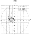
- FIG. 3 illustrates reflection color, which is generated upon irradiating with light at the respective incident angles, plotted in color coordinates in the color space for Samples 1 to 3.
- FIG. 4 illustrates reflection color, which is generated upon irradiating with light at the respective incident angles, plotted in color coordinates in the color space for Samples 4 to 6.
- the region “A” is defined as a range where a* is -5 to 0, and b* is -7.5 to 4.
- the region “A” is defined as a region in which the reflection color does not give a feeling of strangeness based on the experience of the inventors of glass members for vehicles. Typically, in the case of a glass member for vehicle, as the reflection color, colors near white to light blue tend to be preferred to colors of white to pink. Therefore, the region “A” tends to be somewhat broad on the light blue region side (lower left region of the origin).
- a spectrophotometer (U4100 by Hitachi, limited) was used.
- the respective samples are irradiated with light from a lower part (non-film surface, i.e. the second surface 114 side of the laminated glass).
- a visible light reflectance and a visible light transmittance for the respective samples were measured.
- the measurement was performed in compliance with JIS A5759.
- An emissivity for the samples (hemispheric emissivity) on an upper part side (film surface, i.e. the upper part layer side) was measured by using an emissivity meter (TSS-5X by Japan Sensor Corporation).
- total solar transmittance T ts (%) was obtained following the regulations of ISO 13837.
- the present invention can be used for a glass member for vehicle, a window glass member of a building, and the like.
Landscapes
- Chemical & Material Sciences (AREA)
- Engineering & Computer Science (AREA)
- General Chemical & Material Sciences (AREA)
- Life Sciences & Earth Sciences (AREA)
- Chemical Kinetics & Catalysis (AREA)
- Geochemistry & Mineralogy (AREA)
- Materials Engineering (AREA)
- Organic Chemistry (AREA)
- Ceramic Engineering (AREA)
- Structural Engineering (AREA)
- Civil Engineering (AREA)
- Mechanical Engineering (AREA)
- Joining Of Glass To Other Materials (AREA)
- Surface Treatment Of Glass (AREA)
- Laminated Bodies (AREA)
Abstract
Description
- The disclosure herein generally relates to a heat insulating glass unit for vehicle and a manufacturing method thereof.
- Conventionally, heat insulating glass units that can shield against solar energy flowing into an interior of a vehicle such as a car and prevent a temperature inside the vehicle from rising have been known.
- For example,
Patent Document 1 discloses a heat insulating glass manufactured by forming a multilayered film configured with an indium tin oxide (ITO) and a silicon oxide (SiO2) layer on a glass substrate. -
- [PTL 1] Japanese Unexamined Patent Application Publication No.
2004-149400 - [PTL 2] Japanese Translation of
PCT International Application Publication No. JP-T-2015-512854 - The heat insulating glass disclosed in
Patent Document 1 has a feature that a visible light transmittance is high and the heat insulating performance is excellent. - However, the above-described heat insulating glass has a problem such that color characteristics as viewed exhibit angle dependence. That is, the above-described heat insulating glass has a tendency that a color of a reflected light (reflection color) varies by a viewing direction. For example, when the heat insulating glass is viewed from a first direction, the heat insulating glass appears blue, but when the heat insulating glass is viewed from a second direction, the heat insulating glass appears yellow. Because the above-described angle dependence of reflection color for the heat insulating glass creates a strange impression to a user who views the heat insulating glass, it is preferable to control the angle dependence as much as possible.
- Moreover, a plate (glass plate) disclosed in
Patent Document 2 includes a heat radiation and reflection coating, has transparency and corrosion resistance, and has a feature of not being damaged upon a bending process. - However, in the plate disclosed in
Patent Document 2, a barrier layer (e.g. silicon nitride) with a thickness of 10 nm or more is required to be arranged. In this case, not only it becomes difficult to keep the angle dependence of a reflection color within a desired range, but also the visible light transmittance decreases when the barrier layer becomes thicker. Especially, in order to achieve the visible light transmittance required in the case of using the plate for a windshield of a car or the like (e.g. a visible light transmittance Tv of 72% or more), it is necessary to compensate for insufficient transmittance by increasing thickness of a layer above the barrier layer (inPatent Document 2, typically SiO2 or a compound thereof). Thus, productivity deteriorates. - The present invention was made in view of such a problem, and it is an object of the present invention to provide a heat insulating glass unit in which the angle dependence of reflection color is improved. Moreover, the present invention aims at providing a manufacturing method of such a heat insulating glass unit.
- The present invention provides
a heat insulating glass unit for vehicle including
a laminated glass in which a first glass plate and a second glass plate are bonded to each other via an intermediate film;
a color tone compensation film arranged on at least one surface of the laminated glass;
a transparent conductive layer mainly including an indium tin oxide (ITO) arranged on the color tone compensation film; and
an upper part layer arranged on the transparent conductive layer, a refraction index of the upper part layer for a light with a wavelength of 630 nm being 1.7 or less,
the color tone compensation film having at least a first layer and a second layer,
the first layer being arranged at a position closer to the laminated glass than the second layer, and
a refraction index of the first layer for a light with a wavelength of 630 nm being greater than a refraction index of the second layer for a light with a wavelength of 630 nm. - Moreover, the present invention provides
a manufacturing method of a heat insulating glass unit for vehicle including - (i) preparing a first glass plate and a second glass plate;
- (ii) forming a first layer on a first surface of the first glass plate by a sputtering method, and forming a second layer on the first layer, a refraction index of the second layer for a light with a wavelength of 630 nm being less than a refraction index of the first layer, to deposit a color tone compensation film;
- (iii) depositing a transparent conductive layer mainly including an indium tin oxide (ITO) on the color tone compensation film by a sputtering method;
- (iv) depositing an upper part layer on the transparent conductive layer, a refractive index of the upper part layer for a light with a wavelength of 630 nm being 1.7 or less by a sputtering method; and
- (v) bonding the first glass plate and the second glass plate via an intermediate film so that the first surface is arranged on the outside.
- According to an aspect of the present invention, a heat insulating glass unit in which angle dependence of reflection color is rectified can be provided. Moreover, according to an aspect of the present invention, a manufacturing method of such a heat insulating glass unit can be provided.
- Other objects and further features of embodiments will become apparent from the following detailed description when read in conjunction with the accompanying drawings, in which:
- [
FIGURE 1] FIG. 1 is a cross sectional diagram schematically depicting a configuration of a heat insulating glass unit for vehicle according to an embodiment of the present invention. - [
FIGURE 2] FIG. 2 is a diagram schematically illustrating an example of a flowchart of a manufacturing method for the heat insulating glass unit for vehicle according to the embodiment of the present invention. - [
FIGURE 3] FIG. 3 is a diagram in which reflection colors occurring when irradiating with a light at respective incident angles are plotted in color coordinates in a color space forSamples 1 to 3. - [
FIGURE 4] FIG. 4 is a diagram in which reflection colors occurring when irradiating with a light at respective incident angles are plotted in color coordinates in the color space forSamples 4 to 6. - In the following, with reference to drawings, an embodiment of the present invention will be described.
-
FIG. 1 schematically illustrates a cross section of a heat insulating glass unit for vehicle according to an embodiment of the present invention. - As illustrated in
FIG. 1 , the heatinsulating glass unit 100 includes a laminatedglass 110, a colortone compensation film 130, a transparentconductive layer 140, anadhesion improving layer 150, and anupper part layer 160. - The laminated
glass 110 includes afirst surface 112 and asecond surface 114. Each layer (film), which will be described later, is arranged on thefirst surface 112 side. - The laminated
glass 110 is configured by bonding afirst glass plate 115 and asecond glass plate 125 via anintermediate film 120. Therefore, thefirst surface 112 of the laminatedglass 110 corresponds to the outer surface of thefirst glass plate 115, and thesecond surface 114 of the laminatedglass 110 corresponds to the outer surface of thesecond glass plate 125. - The color
tone compensation film 130 is arranged on thefirst surface 112 of the laminatedglass 110. The colortone compensation film 130 has a role of adjusting angle dependence of reflection color of the heat insulating glass unit forvehicle 100 by controlling refraction indices of two or more layers included in the colortone compensation film 130. - In the example illustrated in
FIG. 1 , the colortone compensation film 130 is configured with two layers, i.e. afirst layer 132 and asecond layer 136. In the above-described configuration, a refraction index of thefirst layer 132 for a light with a wavelength of 630 nm is higher than a refraction index of thesecond layer 136 for a light with a wavelength of 630 nm. - However, the above-described configuration is merely an example. The color
tone compensation film 130 may be configured with three layers of more. - The transparent
conductive layer 140 is arranged above the colortone compensation film 130. The transparentconductive layer 140 is configured with a material mainly including an indium tin oxide (ITO). In the present application, the phrase "layer 'A' mainly includes material 'B'" means that a layer 'A' includes a material 'B' of 50 mass% or more. - The refraction index of the transparent
conductive layer 140 for a light with a wavelength of 630 nm falls, for example, within a range of 1.7 to 1.8. - The
adhesion improving layer 150 is arranged between the transparentconductive layer 140 and theupper part layer 160, and has a role of suppressing an exfoliation at an interface between both layers. Theadhesion improving layer 150 is configured, for example, with a metal oxide such as a tin oxide, a zinc oxide, a cerium oxide, and the like. Note that the arrangement of theadhesion improving layer 150 is optional, and theadhesion improving layer 150 may be omitted. - The
upper part layer 160 is arranged on the transparentconductive layer 140, when theadhesion improving layer 150 is absent. When theadhesion improving layer 150 is present, theupper part layer 160 is arranged on theadhesion improving layer 150. In the present application, the term "upper part" in the "upper part layer" means being arranged at a far side from the transparentconductive layer 140 with respect to thelaminated glass 110. Therefore, the expression of the "upper part layer" does not necessarily mean that theupper part layer 160 is an uppermost layer (outermost layer) in the application with respect to the ground. - The
upper part layer 160 has a role of protecting the transparentconductive layer 140 and enhancing durability of the heat insulatingglass unit 100. - However, the
upper part layer 160 is required to be arranged so as not to have adverse effects on color characteristics of the heat insulatingglass unit 100 and the angle dependence thereof. Therefore, theupper part layer 160 is configured so that the refraction index for a light with wavelength of 630 nm is 1.7 or less. Theupper part layer 160 may be configured, for example, with a material mainly including SiO2. - The heat insulating
glass unit 100 having the above-described configuration exerts excellent heat insulating properties. For example, an emissivity of the heat insulatingglass unit 100 is 0.45 or less. Therefore, when the heat insulatingglass unit 100 is applied to, for example, a front glass (windshield), a side glass, a rear glass, and/or a roof glass of an automobile (in the following, they will be referred to as "glass members" as a whole), it becomes possible to significantly control an increase in the temperature inside the vehicle due to an incidence of solar light. - Moreover, the heat insulating
glass unit 100 can significantly control the angle dependence of reflection color according to thecolor compensation film 130 and further interactions between therespective layers 132 to 160. Therefore, when the heat insulatingglass unit 100 is applied to, for example, glass members of automobiles or the like, it becomes possible to significantly control variation of color characteristics depending on a viewing direction. - Furthermore, because the heat insulating
glass unit 100 has theupper part layer 160 having an abrasion-resistance, it becomes possible to enhance the durability of the heat insulatingglass unit 100. For example, when the heat insulatingglass unit 100 is applied to a side glass of an automobile, an occurrence of a scratch when moving the side glass up and down for opening/closing can be reduced significantly. - Especially, when the
upper part layer 160 is mainly configured with silica (SiO2) in the heat insulatingglass unit 100, even if a thinning (wear) occurs in theupper part layer 160, the effect of controlling variation of reflection color depending on a viewing direction continues to be maintained. - Next, respective members configuring the heat insulating glass unit for vehicle according to the embodiment will be described in detail. In the following description, when indicating the respective members, for clarification, the reference numerals used in
FIG. 1 will be used. - The
laminated glass 110 of the heat insulating glass unit forvehicle 100 has twoglass plates - Types of the
respective glass plates glass plates first glass plate 115 and thesecond glass plate 125 may be different from each other. - The
glass plates glass plates - An
intermediate film 120 is arranged between the first andsecond glass plates - The
intermediate film 120 may be configured with, for example, a transparent resin. For the resin, for example, a polyvinyl butyral (PVB), a polyvinyl chloride, and the like can be used. Moreover, an infrared ray shielding PVB containing dispersed pigments is also effective in order to reduce total solar transmittance Tts (%) - Visible light transmittance, solar radiation transmittance, and transmittance for light with wavelength of 1500 nm of the
glass plates - The
glass plates - A shape of the
laminated glass 110 is not necessarily planar. Thelaminated glass 110 may be curved. Moreover, a thickness of thelaminated glass 110 may fall within a range of 2 mm to 6 mm, for example. - The color
tone compensation film 130 has a role of adjusting an angle dependence of reflection color of the heat insulatingglass unit 100. - As described above, the color
tone compensation film 130 is configured with a plurality of layers including at least thefirst layer 132 and thesecond layer 136. - In this case, the
first layer 132 closer to thelaminated glass 110 has a greater refraction index for a light with a wavelength of 630 nm than a refraction index for a light with a wavelength of 630 nm of thesecond layer 136. For example, thefirst layer 132 has a refraction index for a light with a wavelength of 630 nm that falls within a range of 1.7 to 2.5. The refraction index of the first layer preferably falls within a range of 1.8 to 2.3, and more preferably falls within a range of 1.8 to 2.2. - The
second layer 136 has a refraction index for a light with a wavelength of 630 nm that is 1.6 or less. The refraction index of thesecond layer 136 is preferably 1.55 or less. - The
first layer 132 mainly includes an oxide or an oxynitride including at least one of Ti, Nb, Ta, Zn, Al, In, Si, and Zr, for example. Especially, among these, an oxide or an oxynitride including at least one of Ti, Nb, Zn, and In is preferable. Thefirst layer 132 may be, for example, titania in which silica of 0.1 mass% to 10 mass% is doped (silica-doped titania). - When the
first layer 132 is configured with tin oxide, a crack is likely to occur in thefirst layer 132 during a subsequent heating process. Therefore, when the manufacturing process of the heat insulatingglass unit 100 includes a heat treatment step, it is not preferable to configure thefirst layer 132 with tin oxide. - A thickness of the
first layer 132 falls, for example, within a range of 3 nm to 40 nm, and preferably a range of 5 nm to 35 nm. - The
second layer 136 may be configured with a material mainly including any of SiO2, SiON, or MgF2, for example. - A thickness of the
second layer 136 falls, for example, within a range of 5 nm to 50 nm, and preferably a range of 10 nm to 45 nm. - The transparent
conductive layer 140 is configured with a material mainly including an indium tin oxide (ITO). ITO has a function of reflecting infrared light. - ITO may include an additive. Such an additive may be, for example, Ga, Zn, Al, Nb, and/or the like.
- A mass fraction of tin oxide in the ITO falls within a range of 5% to 12.5% of total mass, and preferably falls within a range of 6.5% to 11% of total mass. For tin oxide mass fractions of 12.5% or less, resistance tends to decrease as amount of tin oxide increases.
- Moreover, the transparent
conductive layer 140 may include, in addition to ITO, another material of less than 50 mass% at maximum. Such a material may be, for example, sodium, lead, iron, and/or the like. - A thickness of the transparent
conductive layer 140 falls preferably, for example, within a range of 100 nm - 200 nm, and more preferably within a range of 120 nm to 170 nm. - A refraction index of the transparent
conductive layer 140 for a light with a wavelength of 630 nm preferably falls within a range of 1.7 to 1.8 typically. - The transparent
conductive layer 140 may be configured by, for example, depositing an amorphous ITO layer on the colortone compensation film 130, and crystallizing the ITO layer. According to the crystallization, a heat treatment temperature falls, for example, within a range of 80 °C to 170 °C. By the above-described method, an ITO layer with a low resistance can be obtained. - The
adhesion improving layer 150 is arranged as necessary. By arranging theadhesion improving layer 150, a peel strength may be enhanced between the transparentconductive layer 140 and theupper part layer 160. - The
adhesion improving layer 150 may be configured with a metal oxide such as tin oxide, zinc oxide, cerium oxide and/or the like. - A thickness of the
adhesion improving layer 150 falls preferably, for example, within a range of 1 nm - 10 nm. - The
upper part layer 160 is arranged in order to protect a layer existing below theupper part layer 160, e.g. the transparent conductive layer 140 (and/or the adhesion improving layer 150). For example, by arranging theupper part layer 160 above the transparent conductive layer 140 (and/or the adhesion improving layer 150), it becomes possible to enhance an oxidation resistance of the transparent conductive layer 140 (and/or the adhesion improving layer 150). Moreover, by arranging theupper part layer 160, an abrasion resistance is enhanced, and it becomes possible to control against an occurrence of a thinning (wear), a crack or the like in the transparent conductive layer 140 (and/or the adhesion improving layer 150). - Moreover, when the
upper part layer 160 is arranged appropriately, it becomes possible to enhance the transmittance in the visible light range of the heat insulatingglass unit 100. - The
upper part layer 160 is preferably configured with a material with a refraction index, for a light with a wavelength of 630 nm, of 1.7 or less, and more preferably a material with a refraction index of 1.55 or less. Such a material includes silica (SiO2), SiON, and MgF2. Theupper part layer 160 may be a layer mainly including, for example, silica. In this case, it is possible to enhance heat resistance of the transparentconductive layer 140. Moreover, in the case of the layer mainly including silica, even if a thinning (wear) occurs in theupper part layer 160, it is still possible to maintain the same effect of controlling the angle dependence of reflection color as the heat insulatingglass unit 100 in the initial period. - The
upper part layer 160 may be, for example, a layer of silica in which zirconia is doped (zirconia-doped silica). A dope amount of zirconia with respect to the entireupper part layer 160 preferably falls within a range of 5 mol% to 40 mol%, for example. - A thickness of the
upper part layer 160 is preferably 60 nm or less, for example. The thickness of theupper part layer 160 falls more preferably, for example, within a range of 20 nm - 60 nm. When the thickness of theupper part layer 160 is 60 nm or less, as described below, an effect whereby it becomes relatively easier to control reflection color from the heat insulatingglass unit 100 can be obtained. - The heat insulating
glass unit 100 preferably has an emissivity that falls within a range of 0.1 - 0.45. In the heat insulatingglass unit 100 having such an emissivity, it becomes possible to significantly decrease the heat transmission coefficient for light with wavelengths of infrared and far-infrared. - Note that, in the embodiment, reflection color from the heat insulating
glass unit 100 is represented by CIE1976 L*a*b* color space (Illuminant D65, field of view of 2°) . - Especially, the
heat insulating unit 100 according to the embodiment has a feature that a color space of a reflected light generated when a light enters with an incident angle within a range of 0° to 80° is included in a region of -5 ≤ a* ≤ 0 and -7.5 ≤ b* ≤ 4. Therefore, in the heat insulatingglass unit 100, it is possible to significantly control the angle dependence of reflection color. - The heat insulating
glass unit 100 can be applied, for example, to a glass member of a vehicle. Such a glass member may be, for example, a front windshield, a rear windshield, a side glass, and a roof glass. - In addition, the heat insulating glass unit of the embodiment can also be applied to a window glass of a building, or a glass member of a refrigerating apparatus, a freezer, a show case, and the like.
- When the heat insulating glass unit according to the embodiment is mounted on a vehicle, the heat insulating glass unit is arranged so that a surface on which a film is formed is the vehicle interior side. According to the above-described configuration, the heat insulating glass unit in which the angle dependence is improved can be provided. In addition, the heat insulating glass unit may also be mounted so that the surface on which the film is formed is the vehicle exterior side. According to the above-described configuration, the angle dependence of the heat insulating glass unit is improved, and a heat shield effect can further be obtained.
- Next, with reference to
FIG. 2 , an example of a manufacturing method of a heat insulating glass unit for vehicle according to the embodiment of the present invention having the above-described features will be described. In the following, as an example, the heat insulatingglass unit 100 illustrated inFIG. 1 is employed and a manufacturing method thereof will be described. -
FIG. 2 schematically illustrates an example of a flow of the manufacturing method of the heat insulating glass unit for vehicle according to the embodiment. - As illustrated in
FIG. 2 , the manufacturing method includes
a step of preparing a first glass plate and a second glass plate (step S110);
a step of setting up a color tone compensation film on a first surface of the first glass plate (step S120);
a step of arranging a transparent conductive layer above the color tone compensation film (step S130);
a step of arranging an adhesion improving layer above the transparent conductive layer (step S140);
a step of arranging an upper part layer above the adhesion improving layer (step S150); and
a step of bonding the first glass plate and the second glass plate via an intermediate film so that the first surface is arranged on an outer side of the plates (step S160). - Note that the step S140, i.e. arranging the adhesion improving layer may be omitted.
- In the following, the respective steps will be described in detail. Note that in the following description, when indicating the respective members, for clarification, the reference numerals used in
FIG. 1 will be used. - First, a
first glass plate 115 and asecond glass plate 125 are prepared. - As described above, compositions of the
first glass plate 115 and thesecond glass plate 125 are not particularly limited, and thefirst glass plate 115 and thesecond glass plate 125 may be configured with a soda lime glass, a quartz glass, a borosilicate glass, or an alkali-free glass. - Next, a color
tone compensation film 130 is arranged on one surface (first surface) of thefirst glass plate 115. - As described above, the color
tone compensation film 130 may be formed of a plurality of layers including afirst layer 132 and asecond layer 136. Among them, thefirst layer 132 that is closer to thefirst glass plate 115 is preferably configured with a material mainly including an oxide or an oxynitride including at least one of Ti, Nb, Ta, Zn, Al, In, Si, and Zr, for example. Thefirst layer 132 may be, for example, a layer mainly including a titanium oxide in which silica is doped (silica-doped titania). Thesecond layer 136 may be a layer mainly including silica. - The
first layer 132 and thesecond layer 136 are formed, for example, by a sputtering method, a vacuum evaporation method, an ion plating method, a chemical vapor phase film deposition method, or a wet film deposition method, or the like. Thefirst layer 132 and thesecond layer 136 are preferably formed by using a sputtering method. This is because an environmental burden of the sputtering method is small and a layer obtained by the sputtering method has a relatively uniform thickness. - The sputtering method includes a DC sputtering method, an AC sputtering method, a DC pulse sputtering method, a high frequency sputtering method, a high frequency superposition DC sputtering method, and the like. As the sputtering method, a magnetron sputtering method may be employed.
- The
first layer 132 is deposited with a thickness of, for example, 3 nm to 40 nm, and thesecond layer 136 is deposited with a thickness of, for example, 5 nm to 35 nm. - Next, a transparent
conductive layer 140 mainly including ITO is arranged on the colortone compensation film 130. - The transparent
conductive layer 140 may be deposited by using various sputtering methods in the same way as the case of the colortone compensation film 130. When the transparentconductive layer 140 is an ITO layer, upon depositing the transparentconductive layer 140 by a sputtering method, thelaminated glass 110 is not preferably heated during the deposition. For example, a temperature of theglass plate 110 during the deposition of the ITO layer by a sputtering method is preferably 100 °C or less. - Next, an
adhesion improving layer 150 is arranged on the transparentconductive layer 140. Theadhesion improving layer 150 is configured with, for example, a metal oxide, such as cerium oxide, or zinc oxide. - The method of forming the
adhesion improving layer 150 is not particularly limited. - The
adhesion improving layer 150 may be formed by directly depositing metal oxide using a conventional method such as various sputtering methods. The metal oxide may be, for example, zinc oxide, or cerium oxide. Alternatively, theadhesion improving layer 150 may be formed, for example, by depositing a metal film using a conventional method such as a sputtering method, and then oxygenizing the metal film. The metal film may be, for example, zinc or cerium. - In the latter case, the oxidation treatment for the metal film may be performed after deposition of all layers.
- Note that Step S150 may be omitted.
- Next, an
upper part layer 160 is arranged on the adhesion improving layer 150 (when theadhesion improving layer 150 is absent, on the transparent conductive layer 140). Theupper part layer 160 may be configured with a material mainly including silica. - The
upper part layer 160 may be deposited using various sputtering methods in the same way as the case of the other layers, including the colortone compensation film 130. - Especially, at steps S120 to S150, all of the respective layers are preferably deposited by a sputtering method. In this case, effects of a film being flexible compared with a thermally oxidized film and of a crack not being likely to occur are obtained.
- Note that after forming the
upper part layer 160, the entirelaminated glass 110 may be subjected to the heat treatment (referred to as a "post heat treatment"). Accordingly, the transparentconductive layer 140 and theupper part layer 160 can be formed to be of few defects. - The post heat treatment is performed, for example, in air at a temperature of 550 °C to 750 °C, for about 1 minute to 30 minutes.
- When the heat insulating
glass unit 100 is applied to a front windshield for vehicle or the like, a bending process is performed for theglass plates glass plates - The heat treatment temperature for the bending process overlaps with the temperature of the above-described post heat treatment. Therefore, the post heat treatment and the heat treatment of the bending process may be performed simultaneously.
- As described above, when such heat treatment is performed, it is not preferable to configure the
first layer 132 of the colortone compensation film 130 with tin oxide. This is because when thefirst layer 132 is configured with tin oxide, a breakage or a crack is likely to occur in thefirst layer 132 after the heat treatment. - In addition, on the
upper part layer 160, another layer (for example, alumina, tantalum oxide, silicon nitride, zircon-boron oxide, and the like) may be formed. - Next, the
first glass plate 115 and thesecond glass plate 125 are bonded to each other via anintermediate film 120. At this time, thefirst glass plate 115 is arranged with respect to thesecond glass plate 125 so that the first surface, i.e. the surface, on which the respective layers are formed, is arranged on the outside. Theintermediate film 120 may be a polyvinyl butyral (PVB), or a polyvinyl chloride. - The bonding process is performed by heating and pressurizing a laminated body obtained by arranging the
first glass plate 115 and thesecond glass plate 125 via theintermediate film 120. - According to the above-described processes, the heat insulating
glass unit 100 can be manufactured. - As described above, the manufacturing method of the heat insulating
glass unit 100 has been described briefly. However, the above-described manufacturing method is merely an example, and it is obvious for a person skilled in the art that the heat insulating glass unit according to the embodiment of the present invention can be manufactured by another manufacturing method. - Next, examples of the present invention will be described.
- A sample of the heat insulating glass unit was manufactured with a method described as follows.
- First, two glass plates with a thickness of 2 mm (VFL by Asahi Glass Company, Limited) were prepared. Next, by a sputtering method, on a first surface of one glass plate (first glass plate), as a first layer of a color tone compensation film, titanium oxide including silica (amount of silica was 8 mass%)(refraction index for a light with a wavelength of 630 nm was 2.1537) was deposited. For the deposition, a silica-doped titania target with the amount of silica of 8 mass% was used, and a targeted film thickness was 10 nm.
- Next, by a sputtering method, on the titanium oxide layer including silica, as a second layer of the color tone compensation film, a silica layer (refraction index for a light with a wavelength of 630 nm was 1.4620) was deposited. A targeted film thickness was 35 nm.
- Next, by a sputtering method, on the color tone compensation film (silica-doped titania layer and silica layer), as a transparent conductive layer, an ITO layer was deposited. The targeted film thickness was 150 nm. Note that, upon deposition, the glass plate was not heated. According to the above-described operation, an amorphous ITO layer was obtained. At a later time, an ITO layer that was crystallized by a post heat treatment (refraction index at a wavelength of 630 nm was 1.7606) was formed.
- Next, by a sputtering method, on the ITO layer, as an upper part layer, a silica layer (refraction index at a wavelength of 630 nm was 1.4620) was deposited. A targeted film thickness was 55 nm.
- Afterwards, as the post heat treatment, the first glass plate was heated at 650 °C for 7 minutes.
- Next, the first glass plate, an intermediate film, and a second glass plate were laminated to form a laminated body. For the intermediate film, a PVB of a thermal absorption type (Saflex S Series by Eastman Chemical Company) was used. By heating at 135 °C and pressurizing the laminated body, a sample of the heat insulating glass unit (referred to as a "
sample 1") was obtained. - Note that, at
Sample 1, a thickness of the intermediate film was 0.76 mm. - A sample of the heat insulating glass unit (referred to as a "
sample 2") was manufactured using the same method as Example 1. - In Example 2, the thickness of the silica layer of the upper part layer was 95 nm. The other conditions were the same as in the case of Example 1.
- A sample of the heat insulating glass unit (referred to as a "sample 3") was manufactured using the same method as Example 1.
- In Example 3, as the upper part layer, a silica layer in which zirconia is doped (zirconia-doped silica layer)(refraction index at a wavelength of 630 nm was 1.6831) was deposited. A dope amount of zirconia was 33 mol% of the upper part layer. A targeted thickness of the upper part layer was 55 nm.
- Moreover, in Example 3, as the intermediate layer, a PVB of a thermal absorption type (Solar Control Film by Sekisui Chemical Co., Ltd.) was used. The other conditions were the same as in the case of Example 1.
- A sample of the heat insulating glass unit was manufactured with a method described as follows.
- First, two glass plates with a thickness of 2 mm (VFL by Asahi Glass Company, limited) were prepared. Next, by a sputtering method, on a first surface of one glass plate (first glass plate), as a transparent conductive layer, an ITO layer was deposited. A targeted film thickness was 150 nm. Note that upon deposition the glass plate was not heated. According to the above-described operation, an amorphous ITO layer was obtained.
- Next, by a sputtering method, on the ITO layer, as an upper part layer, a silica layer was deposited. A targeted film thickness was 80 nm.
- Afterwards, as the post heat treatment, the first glass plate was heated at 650 °C for 7 minutes.
- Afterwards, using the same method as Example 1, by bonding the first glass plate and a second glass plate via an intermediate film, a sample of the heat insulating glass unit (referred to as a "
sample 4") was obtained. - A sample of the heat insulating glass unit (referred to as a "
sample 5") was manufactured using the same method as the comparative example 1. - In the comparative example 2, as an upper part layer, a silica layer in which zirconia is doped (zirconia-doped silica layer) was formed. A dope amount of zirconia was 33 mol% with respect to the upper part layer. A thickness of the upper part layer was 80 nm. Moreover, as an intermediate layer, a PVB of a thermal absorption type (Solar Control Film by Sekisui Chemical Co., Ltd.) was used.
- The other conditions were the same as in the case of the comparative example 1.
- A sample of the heat insulating glass unit (referred to as a "
sample 6") was manufactured using the same method as the comparative example 1. - In the comparative example 3, a thickness of an ITO layer was 135 nm. Moreover, as an upper part layer, by a sputtering method, a silicon nitride layer (SiN layer: refraction index at a wavelength of 630 nm was 2.0898) was formed. A thickness of the upper part layer was 46 nm. Moreover, as first and second glass plates, soda lime glass plates with a thickness of 2 mm (FL by Asahi Glass Company, limited) were used, and as an intermediate film, a PVB of a thermal absorption type (Solar Control Film by Sekisui Chemical Co., Ltd.) was used.
- The other conditions were the same as in the case of the comparative example 1.
- First, two glass plates with a thickness of 2 mm (VFL by Asahi Glass Company, Limited) were prepared. Next, by a sputtering method, on a first surface of one glass plate (first glass plate), as a first layer of a color tone compensation film, titanium oxide including silica (amount of silica was 8 mass%)(refraction index for a light with a wavelength of 630 nm was 2.1537) was deposited. For the deposition, a silica doped titania target with the amount of silica of 8 mass% was used, and a targeted film thickness was 10 nm.
- Next, by a sputtering method, on the titanium oxide layer including silica, as a second layer of the color tone compensation film, a silica layer (refraction index for a light with a wavelength of 630 nm was 1.4620) was deposited. A targeted film thickness was 35 nm.
- Next, by a sputtering method, on the color tone compensation film (silica doped titania layer and silca layer), as a transparent conductive layer, an ITO layer was deposited. The targeted film thickness was 150 nm. Note that, upon deposition, the glass plate was not heated. According to the above-described operation, an amorphous ITO layer was obtained. At a later time, an ITO layer that was crystallized by a post heat treatment (refraction index at a wavelength of 630 nm was 1.7606) was formed.
- Next, by a sputtering method, on the ITO layer, as an adhesion improving layer, a silicon nitride layer (SiN layer; refraction index at a wavelength of 630 nm was 2.0898) was deposited. A targeted film thickness was 10 nm.
- Next, by a sputtering method, on the adhesion improving layer, as an upper part layer, a silica layer (refraction index at a wavelength of 630 nm was 1.4620) was deposited. A targeted film thickness was 55 nm.
- Afterwards, as a post heat treatment, the first glass plate was heated at 650 °C for 7 minutes.
- Next, the first glass plate, an intermediate film, and a second glass plate were laminated to form a laminated body. For the intermediate film, a PVB (Saflex S Series by Eastman Chemical Company) was used. By heating at 135 °C and pressurizing the laminated body, a sample of the heat insulating glass unit (referred to as a "sample 7") was obtained.
- TABLE 1, in the following, shows the configurations of the laminated glass and the layer configurations of
Samples 1 to 7 as a whole.[TABLE 1] sample laminated glass layer configuration first glass plate intermediate film second glass plate color tone compensation film transparent conductive layer adhesion improving layer upper part layer first layer second layer 1 VFL Saflex S Series VFL silica doped titania (10 nm) silica (35 nm) ITO (150 nm) - silica (55 nm) 2 VFL Saflex S Series VFL silica doped titania (10 nm) silica (35 nm) ITO (150 nm) - silica (95 nm) 3 VFL Solar Control Film VFL silica doped titania (10 nm) silica (35 nm) ITO (150 nm) - zirconia doped silica (55 nm) 4 VFL Saflex S Series VFL - - ITO(150 nm) - silica (80 nm) 5 VFL Solar Control Film VFL - - ITO (150 nm) - zirconia doped silica (80 nm) 6 FL Solar Control Film FL - - ITO (135 nm) - SiN (46 nm) 7 VFL Saflex S Series VFL silica doped titania (10nm) silica (35 nm) ITO (150 nm) SiN (10 nm) silica (55 nm) - Next, using the
respective samples 1 to 7, the following characteristic evaluation was performed. - Using the respective samples, by the following method, the angle dependence of reflection color was evaluated.
- Using a spectrometer (V570ARM-500N by JASCO Corporation), irradiating with a visible light (wavelength of 300 nm to 800 nm) at a predetermined angle (5° to 70°) from the upper part layer side, an obtained reflection color was measured.
- The obtained reflection color was indicated in the CIE 1976 L*a*b* color space (Illuminant D65, 2° field of view).
- Results of measurements for
Samples 1 to 6 are shown in the following TABLEs 2 to 7. An incident angle (°) is an inclination angle of the incident light from a line (0°) normal to the upper part layer of the sample.[TABLE 2] incident angle (°) reflection color L* a* b* 5 29.2366 -0.9234 0.5249 10 29.3296 -1.1344 0.6817 20 29.6560 -1.7624 1.0646 30 30.3931 -2.7134 1.3789 40 31.9790 -3.6536 1.1644 50 35.3633 -4.0454 0.1877 60 42.1993 -3.6497 -1.0168 70 54.5037 -3.0006 -1.4879 [TABLE 3] incident angle (°) reflection color L* a* b* 5 22.4252 -1.8503 -1.8658 10 22.3885 -1.7186 -1.7036 20 22.4027 -1.4432 -1.1491 30 22.8784 -1.4125 -0.0516 40 24.6129 -2.1152 1.4850 50 28.8776 -3.4829 2.5738 60 37.3036 -4.5948 2.2211 70 51.4528 -4.7582 0.9398 [TABLE 4] incident angle (°) reflection color L* a* b* 5 35.1166 -0.1982 -0.7265 10 35.1379 -0.2926 -0.6011 20 35.2587 -0.6480 -0.2179 30 35.6740 -1.3870 0.3522 40 36.8176 -2.4415 0.7892 50 39.5854 -3.3561 0.6124 60 45.5936 -3.5499 -0.2000 70 56.9972 -3.1013 -0.8195 [TABLE 5] incident angle (°) reflection color L* a* b* 5 26.9014 -12.4863 5.8280 10 26.8352 -12.6533 5.3446 20 26.6757 -12.8822 3.7245 30 26.6250 -12.4381 0.7604 40 27.3238 -10.4941 -3.1082 50 30.2514 -7.0756 -6.3624 60 37.6658 -3.8901 -7.1560 70 51.4817 -2.6099 -5.3056 [TABLE 6] incident angle (°) reflection color L* a* b* 5 38.9798 -11.4320 18.6487 10 38.9672 -11.9073 18.3890 20 38.9343 -13.1077 17.2719 30 38.9522 -14.3688 14.5752 40 39.3525 -14.6792 9.9804 50 41.1020 -13.0757 4.3754 60 46.1778 -9.6617 -0.1098 70 57.1465 -6.2163 -1.6160 [TABLE 7] incident angle (°) reflection color L* a* b* 5 50.8369 -7.6487 -8.1071 10 50.6528 -7.3736 -8.5976 20 50.1321 -6.5221 -9.9527 30 49.4071 -5.0593 -11.7969 40 48.8385 -3.0732 -13.4284 50 49.2650 -0.9741 -13.7574 60 52.3841 0.4058 -11.4877 70 60.9168 0.3300 -6.3326 -
FIG. 3 illustrates reflection color, which is generated upon irradiating with light at the respective incident angles, plotted in color coordinates in the color space forSamples 1 to 3. Similarly,FIG. 4 illustrates reflection color, which is generated upon irradiating with light at the respective incident angles, plotted in color coordinates in the color space forSamples 4 to 6. - In
FIG. 3 andFIG. 4 , for the respective samples, variations in the reflection color occurring when the light incident angle changes from 5° to 70° can be grasped quantitatively. Especially, in the case where irrespective of the incident angle, any colors of the reflection light reflected at a heat insulating glass unit are included in a region "A", it can be said that in the heat insulating glass unit the angle dependence of reflection color is significantly controlled. - The region "A" is defined as a range where a* is -5 to 0, and b* is -7.5 to 4. The region "A" is defined as a region in which the reflection color does not give a feeling of strangeness based on the experience of the inventors of glass members for vehicles. Typically, in the case of a glass member for vehicle, as the reflection color, colors near white to light blue tend to be preferred to colors of white to pink. Therefore, the region "A" tends to be somewhat broad on the light blue region side (lower left region of the origin).
- From
FIG. 3 , is was found that forSamples 1 to 3, even if the incident angle changes from 5° to 70°, the color coordinates of the reflection color remain inside the region "A". Therefore, it was confirmed that forSamples 1 to 3, the angle dependence of reflection color from samples was significantly controlled. - In
FIG. 4 , it was found that forSamples 4 to 6, when the incident angle changes from 5° to 70°, the color coordinates of reflected light greatly deviate from the region "A", and tend to be distributed in an upper left region greatly deviated from the origin (region of strong yellow to yellow-green). Therefore, it was confirmed that forSamples 4 to 6, the angle dependence of reflection color from samples was great, and there was a problem of a strange feeling created upon being viewed. - Next, using
Samples 1 to 3, a visible light reflectance, a visible light transmittance, and emissivity were measured. - For the measurement, a spectrophotometer (U4100 by Hitachi, limited) was used. The respective samples are irradiated with light from a lower part (non-film surface, i.e. the
second surface 114 side of the laminated glass). Within a range of wavelength of light of 300 nm to 2500 nm, a visible light reflectance and a visible light transmittance for the respective samples were measured. The measurement was performed in compliance with JIS A5759. An emissivity for the samples (hemispheric emissivity) on an upper part side (film surface, i.e. the upper part layer side) was measured by using an emissivity meter (TSS-5X by Japan Sensor Corporation). - Furthermore, from obtained results, total solar transmittance Tts (%) was obtained following the regulations of ISO 13837.
- Results of measurement obtained for
Sample 1 are shown in TABLE 8 as a whole:[TABLE 8] incident angle (°) visible light reflectance (%) visible light transmittance (%) hemispheric emissivity total solar transmittance Tts (%) 0 5.9 72.3 0.16 47.45 - Results of measurement obtained for
Sample 2 are shown in TABLE 9 as a whole:[TABLE 9] incident angle (°) visible light reflectance (%) visible light transmittance (%) hemispheric emissivity total solar transmittance Tts (%) 0 3.6 74.0 0.17 48.22 - Results of measurement obtained for Sample 3 are shown in TABLE 10 as a whole:
[TABLE 10] incident angle (°) visible light reflectance (%) visible light transmittance (%) hemispheric emissivity total solar transmittance Tts (%) 0 8.6 75.6 0.16 53.60 - Moreover, two glass plates with a thickness of 2 mm (VFL by Asahi glass Company, Limited) were prepared, films were formed with configurations of
Sample 1 and Sample 7 according to the above-described method, respectively, and a glass withfilm 1 and a glass with film 7 were obtained. Afterwards, a bending test was performed by bending the two glasses with films. Specifically, the glass withfilm 1 and the glass with film 7 were heated at 640 °C for 10 minutes, and were subjected to a bending and molding processing. Both of the glasses with films were bent to an extent such that the bending radius of curvature was about 60 cm. After the bending test, presence or absence of a crack in films was observed. Results of the observation are shown in TABLE 11.[TABLE 11] sample crack in film glass with film 1crack was not detected glass with film 7 crack was not detected - It was found that from the results of the above-described bending test, a presence or absence of an adhesion improving layer did not change the formability, i.e. irrespective of a presence or absence of the adhesion improving layer, a crack did not occur in a film.
- From the above-described results, it was found that any of the visible light reflectance, the visible light transmittance and the emissivity for
Samples 1 to 3, are within a proper range as a heat insulating glass unit for vehicle. In this way, it was confirmed thatSamples 1 to 3 can be applied to a glass member for vehicle. - The present invention can be used for a glass member for vehicle, a window glass member of a building, and the like.
- The present application is based on and claims the benefit of priority of Japanese Priority Application No.
2015-096246 filed on May 11, 2015 -
- 100
- heat insulating glass unit
- 110
- laminated glass
- 112
- first surface of laminated glass
- 114
- second surface of laminated glass
- 115
- first glass plate
- 120
- intermediate film
- 125
- second glass plate
- 130
- color tone compensation film
- 132
- first layer
- 136
- second layer
- 140
- transparent conductive layer
- 150
- adhesion improving layer
- 160
- upper part layer
Claims (10)
- A heat insulating glass unit for vehicle comprising:a laminated glass in which a first glass plate and a second glass plate are bonded to each other via an intermediate film;a color tone compensation film arranged on at least one surface of the laminated glass;a transparent conductive layer mainly including an indium tin oxide (ITO) arranged on the color tone compensation film; andan upper part layer arranged on the transparent conductive layer, a refraction index of the upper part layer for a light with a wavelength of 630 nm being 1.7 or less,wherein the color tone compensation film has at least a first layer and a second layer,wherein the first layer is arranged at a position closer to the laminated glass than the second layer, andwherein a refraction index of the first layer for a light with a wavelength of 630 nm is greater than a refraction index of the second layer for a light with a wavelength of 630 nm.
- The heat insulating glass unit for vehicle according to claim 1,
wherein a thickness of the transparent conductive layer is within a range of 100 nm to 200 nm. - The heat insulating glass unit for vehicle according to claim 1 or 2,
wherein the upper part layer has a thickness of 60 nm or less. - The heat insulating glass unit for vehicle according to any one of claims 1 to 3, further comprising:
an adhesion improving layer between the transparent conductive layer and the upper part layer. - The heat insulating glass unit for vehicle according to claim 4,
wherein a thickness of the adhesion improving layer is less than 10 nm. - The heat insulating glass unit for vehicle according to any one of claims 1 to 5,
wherein the upper part layer mainly includes SiO2. - The heat insulating glass unit for vehicle according to any one of claims 1 to 6,
wherein the first layer includes an oxide or an oxynitride including at least one of Ti, Nb, Ta, Zn, Al, In, Si, and Zr, and/or
wherein the second layer mainly includes SiO2. - The heat insulating glass unit for vehicle according to any one of claims 1 to 7,
wherein an emissivity is 0.45 or less. - A manufacturing method of a heat insulating glass unit for vehicle comprising:(i) preparing a first glass plate and a second glass plate;(ii) forming a first layer on a first surface of the first glass plate by a sputtering method, and forming a second layer on the first layer, a refraction index of the second layer for a light with a wavelength of 630 nm being less than a refraction index of the first layer, to deposit a color tone compensation film;(iii) depositing a transparent conductive layer mainly including an indium tin oxide (ITO) on the color tone compensation film by a sputtering method;(iv) depositing an upper part layer on the transparent conductive layer by a sputtering method, a refractive index of the upper part layer for a light with a wavelength of 630 nm being 1.7 or less; and(v) bonding the first glass plate and the second glass plate via an intermediate film so that the first surface is arranged on an outside of the plates.
- The manufacturing method according to claim 9,
wherein the first layer includes an oxide or an oxynitride including at least one of Ti, Nb, Ta, Zn, Al, In, and Zr, and/or
wherein the second layer mainly includes SiO2.
Applications Claiming Priority (2)
| Application Number | Priority Date | Filing Date | Title |
|---|---|---|---|
| JP2015096246 | 2015-05-11 | ||
| PCT/JP2016/061739 WO2016181740A1 (en) | 2015-05-11 | 2016-04-11 | Insulated glass unit for vehicles, and production method therefor |
Publications (3)
| Publication Number | Publication Date |
|---|---|
| EP3296277A1 true EP3296277A1 (en) | 2018-03-21 |
| EP3296277A4 EP3296277A4 (en) | 2019-02-06 |
| EP3296277B1 EP3296277B1 (en) | 2021-01-13 |
Family
ID=57247954
Family Applications (1)
| Application Number | Title | Priority Date | Filing Date |
|---|---|---|---|
| EP16792465.3A Active EP3296277B1 (en) | 2015-05-11 | 2016-04-11 | Heat insulating glass unit for vehicle and manufacturing method thereof |
Country Status (5)
| Country | Link |
|---|---|
| US (1) | US10576713B2 (en) |
| EP (1) | EP3296277B1 (en) |
| JP (1) | JPWO2016181740A1 (en) |
| CN (1) | CN107531566A (en) |
| WO (1) | WO2016181740A1 (en) |
Families Citing this family (14)
| Publication number | Priority date | Publication date | Assignee | Title |
|---|---|---|---|---|
| US10556821B2 (en) * | 2017-04-26 | 2020-02-11 | Guardian Glass, LLC | Laminated window including different glass substrates with low-E coating adjacent vehicle or building interior and/or methods of making the same |
| US20190040523A1 (en) * | 2017-08-04 | 2019-02-07 | Vitro Flat Glass, LLC | Method of Decreasing Sheet Resistance in an Article Coated with a Transparent Conductive Oxide |
| WO2019123877A1 (en) * | 2017-12-20 | 2019-06-27 | Agc株式会社 | Heat insulating glass |
| JP7491840B2 (en) * | 2018-04-19 | 2024-05-28 | Agc株式会社 | Vehicle door glass |
| JP7160091B2 (en) * | 2018-04-19 | 2022-10-25 | Agc株式会社 | vehicle windshield |
| CN109397790A (en) * | 2018-11-27 | 2019-03-01 | 宁波全亮照明科技有限公司 | Chinese herbaceous peony the gear multi-functional composite glass structure of lifting and its manufacturing method |
| CN114981707B (en) * | 2020-01-15 | 2024-04-30 | Agc株式会社 | Head-up display system |
| CN112644113A (en) * | 2020-12-22 | 2021-04-13 | 武爱平 | Automobile heat-insulating laminated glass and manufacturing method thereof |
| CN113031276B (en) * | 2021-03-29 | 2022-05-10 | 福耀玻璃工业集团股份有限公司 | Head-up display system |
| CN113238378B (en) * | 2021-04-14 | 2022-07-19 | 福耀玻璃工业集团股份有限公司 | Head-up display system |
| TWI823718B (en) * | 2021-12-17 | 2023-11-21 | 正達國際光電股份有限公司 | Display cover glass |
| KR20240171112A (en) * | 2022-03-31 | 2024-12-06 | 비트로 플랫 글래스 엘엘씨 | Articles coated with a multilayer coating laminate |
| CN115519857A (en) * | 2022-08-11 | 2022-12-27 | 福耀玻璃工业集团股份有限公司 | Light control glass and vehicle |
| EP4553051A1 (en) * | 2023-11-07 | 2025-05-14 | AGP Worldwide Operations GmbH | Glazing with low-emissivity coating and enhanced bendability |
Family Cites Families (58)
| Publication number | Priority date | Publication date | Assignee | Title |
|---|---|---|---|---|
| US3881043A (en) * | 1971-06-21 | 1975-04-29 | Ppg Industries Inc | Laminated safety windshields |
| EP0486475B1 (en) * | 1988-03-03 | 1997-12-03 | Asahi Glass Company Ltd. | Amorphous oxide film and article having such film thereon |
| JPH03187736A (en) * | 1989-03-07 | 1991-08-15 | Asahi Glass Co Ltd | Heat rays barrier glass |
| US5318830A (en) * | 1991-05-29 | 1994-06-07 | Central Glass Company, Limited | Glass pane with reflectance reducing coating |
| US5667880A (en) * | 1992-07-20 | 1997-09-16 | Fuji Photo Optical Co., Ltd. | Electroconductive antireflection film |
| JPH07210085A (en) * | 1994-01-18 | 1995-08-11 | Toppan Printing Co Ltd | sticker |
| JPH09188547A (en) * | 1996-01-05 | 1997-07-22 | Sekisui Chem Co Ltd | Intermediate film for laminated glass and laminated glass |
| GB2324098A (en) * | 1997-04-08 | 1998-10-14 | Pilkington Plc | Solar control coated glass |
| JP4013329B2 (en) * | 1997-05-21 | 2007-11-28 | 旭硝子株式会社 | Laminate and glass laminate for window |
| US6165598A (en) * | 1998-08-14 | 2000-12-26 | Libbey-Owens-Ford Co. | Color suppressed anti-reflective glass |
| US6309753B1 (en) * | 1998-08-31 | 2001-10-30 | Corning Incorporated | Coated ultraviolet absorbing glass |
| FR2787440B1 (en) * | 1998-12-21 | 2001-12-07 | Saint Gobain Vitrage | TRANSPARENT SUBSTRATE HAVING AN ANTI-REFLECTIVE COATING |
| US6797388B1 (en) * | 1999-03-18 | 2004-09-28 | Ppg Industries Ohio, Inc. | Methods of making low haze coatings and the coatings and coated articles made thereby |
| FR2800998B1 (en) * | 1999-11-17 | 2002-04-26 | Saint Gobain Vitrage | TRANSPARENT SUBSTRATE HAVING AN ANTI-REFLECTIVE COATING |
| US20040005482A1 (en) * | 2001-04-17 | 2004-01-08 | Tomio Kobayashi | Antireflection film and antireflection layer-affixed plastic substrate |
| US20030035939A1 (en) * | 2001-08-06 | 2003-02-20 | Nippon Sheet Glass Co., Ltd. | Windowpane for head up display and method for manufacturing the same |
| JP2004013081A (en) * | 2002-06-11 | 2004-01-15 | Nikon Corp | Composite optical element, method of manufacturing composite optical element, and optical device |
| GB0216787D0 (en) * | 2002-07-19 | 2002-08-28 | Pilkington Plc | Laminated glazing panel |
| JP2004149400A (en) | 2002-09-02 | 2004-05-27 | Asahi Glass Co Ltd | Insulated glass and method for producing the same |
| US20050196623A1 (en) * | 2004-03-03 | 2005-09-08 | Mckown Clem S.Jr. | Solar control coated glass composition |
| KR101224731B1 (en) * | 2004-05-20 | 2013-01-21 | 후지필름 가부시키가이샤 | Polarization plate with antireflection function, process for producing the same, and image display unit utilizing the same |
| MX2007009319A (en) * | 2005-02-03 | 2007-11-06 | Sekisui Chemical Co Ltd | Intermediate film for laminated glass and laminated glass. |
| US20070108043A1 (en) * | 2005-11-14 | 2007-05-17 | Guardian Industries Corp. | Sputtering target including titanium silicon oxide and method of making coated article using the same |
| US8679302B2 (en) * | 2005-11-14 | 2014-03-25 | Guardian Industries Corp. | Silicon titanium oxide coating, coated article including silicon titanium oxide coating, and method of making the same |
| US20070113881A1 (en) * | 2005-11-22 | 2007-05-24 | Guardian Industries Corp. | Method of making solar cell with antireflective coating using combustion chemical vapor deposition (CCVD) and corresponding product |
| FR2898295B1 (en) * | 2006-03-10 | 2013-08-09 | Saint Gobain | TRANSPARENT ANTIREFLECTION SUBSTRATE WITH NEUTRAL COLOR IN REFLECTION |
| WO2008123553A1 (en) | 2007-04-04 | 2008-10-16 | Asahi Glass Company, Limited | Antifouling member and laminated glass using the same |
| SG185934A1 (en) * | 2007-10-30 | 2012-12-28 | 3M Innovative Properties Co | Multi-stack optical bandpass film with electro magnetic interference shielding for optical display filters |
| US8350451B2 (en) * | 2008-06-05 | 2013-01-08 | 3M Innovative Properties Company | Ultrathin transparent EMI shielding film comprising a polymer basecoat and crosslinked polymer transparent dielectric layer |
| US7998586B2 (en) * | 2008-11-19 | 2011-08-16 | Ppg Industries Ohio, Inc. | Undercoating layers providing improved topcoat functionality |
| US9366783B2 (en) * | 2009-12-21 | 2016-06-14 | Ppg Industries Ohio, Inc. | Silicon thin film solar cell having improved underlayer coating |
| US20110146768A1 (en) * | 2009-12-21 | 2011-06-23 | Ppg Industries Ohio, Inc. | Silicon thin film solar cell having improved underlayer coating |
| FR2956659B1 (en) * | 2010-02-22 | 2014-10-10 | Saint Gobain | LAYER COATED VERTICAL SUBSTRATE WITH IMPROVED MECHANICAL STRENGTH |
| JP2011191338A (en) * | 2010-03-11 | 2011-09-29 | Etsumi Kogaku:Kk | Transparent coloring article |
| FR2963343B1 (en) * | 2010-07-28 | 2012-07-27 | Saint Gobain | GLAZING WITH COATING AGAINST CONDENSATION |
| FR2968774B1 (en) * | 2010-12-10 | 2013-02-08 | Essilor Int | OPTICAL ARTICLE COMPRISING A LOW REFLECTIVE ANTIREFLECTION COATING IN THE ULTRAVIOLET DOMAIN AND THE VISIBLE DOMAIN |
| FR2973023B1 (en) * | 2011-03-25 | 2019-08-02 | Saint-Gobain Glass France | MULTIPLE INSULATION GLAZING COMPRISING TWO LOW EMISSIVE STACKS |
| JP5998124B2 (en) * | 2011-03-31 | 2016-09-28 | 旭硝子株式会社 | Organic LED element, translucent substrate, and manufacturing method of translucent substrate |
| BE1019988A3 (en) * | 2011-05-24 | 2013-03-05 | Agc Glass Europe | TRANSPARENT VERRIER SUBSTRATE CARRYING A COATING OF SUCCESSIVE LAYERS. |
| BE1020051A3 (en) * | 2011-07-04 | 2013-04-02 | Agc Glass Europe | AUTOMOBILE GLAZING. |
| WO2013131667A1 (en) | 2012-03-05 | 2013-09-12 | Saint-Gobain Glass France | Sheet with coating which reflects thermal radiation |
| FR2987618B1 (en) * | 2012-03-05 | 2014-02-28 | Saint Gobain | ANTICONDENSATION GLAZING |
| KR101890781B1 (en) * | 2012-03-30 | 2018-08-22 | 어플라이드 머티어리얼스, 인코포레이티드 | Transparent body for use in a touch panel and its manufacturing method and apparatus |
| JP5885595B2 (en) * | 2012-06-12 | 2016-03-15 | キヤノン株式会社 | Antireflection film, and optical element, optical system, and optical apparatus having the same |
| MX374232B (en) * | 2012-08-01 | 2025-03-05 | Saint Gobain | GLAZING PANEL WITH ELECTRICAL CONNECTION MEANS. |
| US20140113120A1 (en) * | 2012-10-19 | 2014-04-24 | Ppg Industries Ohio, Inc. | Anti-color banding topcoat for coated articles |
| KR101820219B1 (en) * | 2013-02-20 | 2018-01-18 | 쌩-고벵 글래스 프랑스 | Panel with a coating which reflects thermal radiation |
| FR3002534B1 (en) * | 2013-02-27 | 2018-04-13 | Saint-Gobain Glass France | SUBSTRATE COATED WITH A LOW EMISSIVE STACK. |
| US9359261B2 (en) * | 2013-05-07 | 2016-06-07 | Corning Incorporated | Low-color scratch-resistant articles with a multilayer optical film |
| US9110230B2 (en) * | 2013-05-07 | 2015-08-18 | Corning Incorporated | Scratch-resistant articles with retained optical properties |
| US9703011B2 (en) * | 2013-05-07 | 2017-07-11 | Corning Incorporated | Scratch-resistant articles with a gradient layer |
| CN105359005B (en) * | 2013-07-05 | 2018-01-12 | 埃西勒国际通用光学公司 | Optical articles comprising antireflective coatings having very low reflection in the visible region |
| FR3010074B1 (en) * | 2013-09-05 | 2019-08-02 | Saint-Gobain Glass France | METHOD FOR MANUFACTURING A MATERIAL COMPRISING A SUBSTRATE HAVING A FUNCTIONAL LAYER BASED ON TIN OXIDE AND INDIUM |
| FR3012133B1 (en) * | 2013-10-17 | 2021-01-01 | Saint Gobain | PROCESS FOR OBTAINING A SUBSTRATE COATED BY A STACK CONTAINING A TRANSPARENT CONDUCTIVE OXIDE LAYER |
| FR3019173B1 (en) * | 2014-03-28 | 2016-03-25 | Saint Gobain | GLAZING PROVIDED WITH A STACK OF THIN LAYERS FOR SOLAR PROTECTION |
| EP3567201B1 (en) * | 2014-06-11 | 2023-04-19 | Nippon Sheet Glass Company, Limited | Multi-layered glass unit and glass plate for multi-layered glass unit |
| CN104310798B (en) * | 2014-10-10 | 2017-01-11 | 武汉理工大学 | Preparation method of thermotropic reflective infrared coated glass |
| EP3541762B1 (en) * | 2016-11-17 | 2022-03-02 | Cardinal CG Company | Static-dissipative coating technology |
-
2016
- 2016-04-11 JP JP2017517831A patent/JPWO2016181740A1/en active Pending
- 2016-04-11 CN CN201680026760.7A patent/CN107531566A/en active Pending
- 2016-04-11 EP EP16792465.3A patent/EP3296277B1/en active Active
- 2016-04-11 WO PCT/JP2016/061739 patent/WO2016181740A1/en not_active Ceased
-
2017
- 2017-10-16 US US15/784,348 patent/US10576713B2/en active Active
Also Published As
| Publication number | Publication date |
|---|---|
| US20180043658A1 (en) | 2018-02-15 |
| EP3296277A4 (en) | 2019-02-06 |
| WO2016181740A1 (en) | 2016-11-17 |
| US10576713B2 (en) | 2020-03-03 |
| JPWO2016181740A1 (en) | 2018-03-01 |
| CN107531566A (en) | 2018-01-02 |
| EP3296277B1 (en) | 2021-01-13 |
Similar Documents
| Publication | Publication Date | Title |
|---|---|---|
| EP3296277B1 (en) | Heat insulating glass unit for vehicle and manufacturing method thereof | |
| US12174374B2 (en) | Projection assembly for a head-up display (HUD) with p-polarised radiation | |
| KR102589372B1 (en) | Projection device for head-up display (HUD) with p-polarized radiation | |
| KR102626086B1 (en) | Projection device for head-up display (HUD) with p-polarized radiation | |
| CN102918433B (en) | Solar control window and door glazing with low solar factor | |
| US20250231322A1 (en) | Article Having a High Visible Light Reflectance and a Neutral Color | |
| CN111051958B (en) | laminated window glass | |
| KR101728620B1 (en) | Pane having a coating that reflects thermal radiation | |
| US10618838B2 (en) | Heat insulating glass unit for vehicle | |
| KR101676233B1 (en) | Sheet with coating which reflects thermal radiation | |
| CN101243022B (en) | Infrared reflective glass panels and laminated glass for car windows | |
| KR20200040305A (en) | Head-up display and coating for it | |
| CN110650844A (en) | Laminated glass panel with conductive coating and anti-reflection coating | |
| US20080206533A1 (en) | Laminated glass for vehicle window | |
| RU2690459C1 (en) | Heated multilayer glass with thin inner glass and thin outer glass | |
| CN111601779B (en) | Solar control glass panel comprising two titanium nitride based layers | |
| WO2007020792A1 (en) | Infrared reflective glass plate and laminated glass for vehicle window | |
| US12447721B2 (en) | Projection assembly for a head-up display (HUD) with p-polarized radiation | |
| US20230176374A1 (en) | Projection arrangement for a head-up display (hud) with p-polarised radiation | |
| US12528735B2 (en) | Vehicle window with an IR-reflective coating with a discontinuous metallic layer of metal nanocrystals | |
| US20250155614A1 (en) | Projection assembly for a head-up display (hud) with p-polarized radiation | |
| US20250028169A1 (en) | Laminated pane with an electrically conductive coating and local anti-reflection coating | |
| US20240269965A1 (en) | Projection assembly for a head-up display (hud) with p-polarized radiation | |
| TW202605419A (en) | Cellular compatible coating | |
| FR3159385A1 (en) | Process for obtaining curved laminated glazing |
Legal Events
| Date | Code | Title | Description |
|---|---|---|---|
| STAA | Information on the status of an ep patent application or granted ep patent |
Free format text: STATUS: THE INTERNATIONAL PUBLICATION HAS BEEN MADE |
|
| PUAI | Public reference made under article 153(3) epc to a published international application that has entered the european phase |
Free format text: ORIGINAL CODE: 0009012 |
|
| STAA | Information on the status of an ep patent application or granted ep patent |
Free format text: STATUS: REQUEST FOR EXAMINATION WAS MADE |
|
| 17P | Request for examination filed |
Effective date: 20171026 |
|
| AK | Designated contracting states |
Kind code of ref document: A1 Designated state(s): AL AT BE BG CH CY CZ DE DK EE ES FI FR GB GR HR HU IE IS IT LI LT LU LV MC MK MT NL NO PL PT RO RS SE SI SK SM TR |
|
| AX | Request for extension of the european patent |
Extension state: BA ME |
|
| DAV | Request for validation of the european patent (deleted) | ||
| DAX | Request for extension of the european patent (deleted) | ||
| RAP1 | Party data changed (applicant data changed or rights of an application transferred) |
Owner name: AGC INC. |
|
| A4 | Supplementary search report drawn up and despatched |
Effective date: 20190108 |
|
| RIC1 | Information provided on ipc code assigned before grant |
Ipc: C03C 17/34 20060101AFI20190102BHEP Ipc: B32B 17/08 20060101ALI20190102BHEP Ipc: B32B 9/00 20060101ALI20190102BHEP Ipc: B32B 7/02 20190101ALI20190102BHEP Ipc: B32B 17/10 20060101ALI20190102BHEP Ipc: B60J 1/00 20060101ALI20190102BHEP |
|
| STAA | Information on the status of an ep patent application or granted ep patent |
Free format text: STATUS: EXAMINATION IS IN PROGRESS |
|
| 17Q | First examination report despatched |
Effective date: 20200624 |
|
| REG | Reference to a national code |
Ref country code: DE Ref legal event code: R079 Ref document number: 602016051447 Country of ref document: DE Free format text: PREVIOUS MAIN CLASS: C03C0027120000 Ipc: C03C0017340000 |
|
| GRAP | Despatch of communication of intention to grant a patent |
Free format text: ORIGINAL CODE: EPIDOSNIGR1 |
|
| STAA | Information on the status of an ep patent application or granted ep patent |
Free format text: STATUS: GRANT OF PATENT IS INTENDED |
|
| RIC1 | Information provided on ipc code assigned before grant |
Ipc: C03C 27/10 20060101ALI20200924BHEP Ipc: B60J 1/00 20060101ALI20200924BHEP Ipc: E06B 3/66 20060101ALI20200924BHEP Ipc: B32B 17/08 20060101ALI20200924BHEP Ipc: B32B 9/00 20060101ALI20200924BHEP Ipc: C03C 17/36 20060101ALI20200924BHEP Ipc: B32B 17/10 20060101ALI20200924BHEP Ipc: C03C 17/34 20060101AFI20200924BHEP Ipc: B32B 7/02 20190101ALI20200924BHEP |
|
| INTG | Intention to grant announced |
Effective date: 20201019 |
|
| GRAS | Grant fee paid |
Free format text: ORIGINAL CODE: EPIDOSNIGR3 |
|
| GRAA | (expected) grant |
Free format text: ORIGINAL CODE: 0009210 |
|
| STAA | Information on the status of an ep patent application or granted ep patent |
Free format text: STATUS: THE PATENT HAS BEEN GRANTED |
|
| AK | Designated contracting states |
Kind code of ref document: B1 Designated state(s): AL AT BE BG CH CY CZ DE DK EE ES FI FR GB GR HR HU IE IS IT LI LT LU LV MC MK MT NL NO PL PT RO RS SE SI SK SM TR |
|
| REG | Reference to a national code |
Ref country code: GB Ref legal event code: FG4D |
|
| REG | Reference to a national code |
Ref country code: CH Ref legal event code: EP |
|
| REG | Reference to a national code |
Ref country code: DE Ref legal event code: R096 Ref document number: 602016051447 Country of ref document: DE |
|
| REG | Reference to a national code |
Ref country code: IE Ref legal event code: FG4D |
|
| REG | Reference to a national code |
Ref country code: AT Ref legal event code: REF Ref document number: 1354442 Country of ref document: AT Kind code of ref document: T Effective date: 20210215 |
|
| REG | Reference to a national code |
Ref country code: AT Ref legal event code: MK05 Ref document number: 1354442 Country of ref document: AT Kind code of ref document: T Effective date: 20210113 |
|
| REG | Reference to a national code |
Ref country code: NL Ref legal event code: MP Effective date: 20210113 |
|
| REG | Reference to a national code |
Ref country code: LT Ref legal event code: MG9D |
|
| PG25 | Lapsed in a contracting state [announced via postgrant information from national office to epo] |
Ref country code: GR Free format text: LAPSE BECAUSE OF FAILURE TO SUBMIT A TRANSLATION OF THE DESCRIPTION OR TO PAY THE FEE WITHIN THE PRESCRIBED TIME-LIMIT Effective date: 20210414 Ref country code: FI Free format text: LAPSE BECAUSE OF FAILURE TO SUBMIT A TRANSLATION OF THE DESCRIPTION OR TO PAY THE FEE WITHIN THE PRESCRIBED TIME-LIMIT Effective date: 20210113 Ref country code: HR Free format text: LAPSE BECAUSE OF FAILURE TO SUBMIT A TRANSLATION OF THE DESCRIPTION OR TO PAY THE FEE WITHIN THE PRESCRIBED TIME-LIMIT Effective date: 20210113 Ref country code: NO Free format text: LAPSE BECAUSE OF FAILURE TO SUBMIT A TRANSLATION OF THE DESCRIPTION OR TO PAY THE FEE WITHIN THE PRESCRIBED TIME-LIMIT Effective date: 20210413 Ref country code: PT Free format text: LAPSE BECAUSE OF FAILURE TO SUBMIT A TRANSLATION OF THE DESCRIPTION OR TO PAY THE FEE WITHIN THE PRESCRIBED TIME-LIMIT Effective date: 20210513 Ref country code: LT Free format text: LAPSE BECAUSE OF FAILURE TO SUBMIT A TRANSLATION OF THE DESCRIPTION OR TO PAY THE FEE WITHIN THE PRESCRIBED TIME-LIMIT Effective date: 20210113 Ref country code: BG Free format text: LAPSE BECAUSE OF FAILURE TO SUBMIT A TRANSLATION OF THE DESCRIPTION OR TO PAY THE FEE WITHIN THE PRESCRIBED TIME-LIMIT Effective date: 20210413 |
|
| PG25 | Lapsed in a contracting state [announced via postgrant information from national office to epo] |
Ref country code: SE Free format text: LAPSE BECAUSE OF FAILURE TO SUBMIT A TRANSLATION OF THE DESCRIPTION OR TO PAY THE FEE WITHIN THE PRESCRIBED TIME-LIMIT Effective date: 20210113 Ref country code: AT Free format text: LAPSE BECAUSE OF FAILURE TO SUBMIT A TRANSLATION OF THE DESCRIPTION OR TO PAY THE FEE WITHIN THE PRESCRIBED TIME-LIMIT Effective date: 20210113 Ref country code: LV Free format text: LAPSE BECAUSE OF FAILURE TO SUBMIT A TRANSLATION OF THE DESCRIPTION OR TO PAY THE FEE WITHIN THE PRESCRIBED TIME-LIMIT Effective date: 20210113 Ref country code: PL Free format text: LAPSE BECAUSE OF FAILURE TO SUBMIT A TRANSLATION OF THE DESCRIPTION OR TO PAY THE FEE WITHIN THE PRESCRIBED TIME-LIMIT Effective date: 20210113 Ref country code: RS Free format text: LAPSE BECAUSE OF FAILURE TO SUBMIT A TRANSLATION OF THE DESCRIPTION OR TO PAY THE FEE WITHIN THE PRESCRIBED TIME-LIMIT Effective date: 20210113 |
|
| PG25 | Lapsed in a contracting state [announced via postgrant information from national office to epo] |
Ref country code: IS Free format text: LAPSE BECAUSE OF FAILURE TO SUBMIT A TRANSLATION OF THE DESCRIPTION OR TO PAY THE FEE WITHIN THE PRESCRIBED TIME-LIMIT Effective date: 20210513 |
|
| REG | Reference to a national code |
Ref country code: DE Ref legal event code: R097 Ref document number: 602016051447 Country of ref document: DE |
|
| PG25 | Lapsed in a contracting state [announced via postgrant information from national office to epo] |
Ref country code: CZ Free format text: LAPSE BECAUSE OF FAILURE TO SUBMIT A TRANSLATION OF THE DESCRIPTION OR TO PAY THE FEE WITHIN THE PRESCRIBED TIME-LIMIT Effective date: 20210113 Ref country code: EE Free format text: LAPSE BECAUSE OF FAILURE TO SUBMIT A TRANSLATION OF THE DESCRIPTION OR TO PAY THE FEE WITHIN THE PRESCRIBED TIME-LIMIT Effective date: 20210113 Ref country code: SM Free format text: LAPSE BECAUSE OF FAILURE TO SUBMIT A TRANSLATION OF THE DESCRIPTION OR TO PAY THE FEE WITHIN THE PRESCRIBED TIME-LIMIT Effective date: 20210113 |
|
| PLBE | No opposition filed within time limit |
Free format text: ORIGINAL CODE: 0009261 |
|
| STAA | Information on the status of an ep patent application or granted ep patent |
Free format text: STATUS: NO OPPOSITION FILED WITHIN TIME LIMIT |
|
| PG25 | Lapsed in a contracting state [announced via postgrant information from national office to epo] |
Ref country code: DK Free format text: LAPSE BECAUSE OF FAILURE TO SUBMIT A TRANSLATION OF THE DESCRIPTION OR TO PAY THE FEE WITHIN THE PRESCRIBED TIME-LIMIT Effective date: 20210113 Ref country code: MC Free format text: LAPSE BECAUSE OF FAILURE TO SUBMIT A TRANSLATION OF THE DESCRIPTION OR TO PAY THE FEE WITHIN THE PRESCRIBED TIME-LIMIT Effective date: 20210113 Ref country code: SK Free format text: LAPSE BECAUSE OF FAILURE TO SUBMIT A TRANSLATION OF THE DESCRIPTION OR TO PAY THE FEE WITHIN THE PRESCRIBED TIME-LIMIT Effective date: 20210113 Ref country code: RO Free format text: LAPSE BECAUSE OF FAILURE TO SUBMIT A TRANSLATION OF THE DESCRIPTION OR TO PAY THE FEE WITHIN THE PRESCRIBED TIME-LIMIT Effective date: 20210113 |
|
| 26N | No opposition filed |
Effective date: 20211014 |
|
| GBPC | Gb: european patent ceased through non-payment of renewal fee |
Effective date: 20210413 |
|
| PG25 | Lapsed in a contracting state [announced via postgrant information from national office to epo] |
Ref country code: LU Free format text: LAPSE BECAUSE OF NON-PAYMENT OF DUE FEES Effective date: 20210411 |
|
| REG | Reference to a national code |
Ref country code: BE Ref legal event code: MM Effective date: 20210430 |
|
| PG25 | Lapsed in a contracting state [announced via postgrant information from national office to epo] |
Ref country code: AL Free format text: LAPSE BECAUSE OF FAILURE TO SUBMIT A TRANSLATION OF THE DESCRIPTION OR TO PAY THE FEE WITHIN THE PRESCRIBED TIME-LIMIT Effective date: 20210113 Ref country code: CH Free format text: LAPSE BECAUSE OF NON-PAYMENT OF DUE FEES Effective date: 20210430 Ref country code: LI Free format text: LAPSE BECAUSE OF NON-PAYMENT OF DUE FEES Effective date: 20210430 Ref country code: FR Free format text: LAPSE BECAUSE OF NON-PAYMENT OF DUE FEES Effective date: 20210430 Ref country code: GB Free format text: LAPSE BECAUSE OF NON-PAYMENT OF DUE FEES Effective date: 20210413 Ref country code: ES Free format text: LAPSE BECAUSE OF FAILURE TO SUBMIT A TRANSLATION OF THE DESCRIPTION OR TO PAY THE FEE WITHIN THE PRESCRIBED TIME-LIMIT Effective date: 20210113 |
|
| PG25 | Lapsed in a contracting state [announced via postgrant information from national office to epo] |
Ref country code: SI Free format text: LAPSE BECAUSE OF FAILURE TO SUBMIT A TRANSLATION OF THE DESCRIPTION OR TO PAY THE FEE WITHIN THE PRESCRIBED TIME-LIMIT Effective date: 20210113 |
|
| PG25 | Lapsed in a contracting state [announced via postgrant information from national office to epo] |
Ref country code: IT Free format text: LAPSE BECAUSE OF FAILURE TO SUBMIT A TRANSLATION OF THE DESCRIPTION OR TO PAY THE FEE WITHIN THE PRESCRIBED TIME-LIMIT Effective date: 20210113 Ref country code: IE Free format text: LAPSE BECAUSE OF NON-PAYMENT OF DUE FEES Effective date: 20210411 |
|
| PG25 | Lapsed in a contracting state [announced via postgrant information from national office to epo] |
Ref country code: IS Free format text: LAPSE BECAUSE OF FAILURE TO SUBMIT A TRANSLATION OF THE DESCRIPTION OR TO PAY THE FEE WITHIN THE PRESCRIBED TIME-LIMIT Effective date: 20210513 |
|
| PG25 | Lapsed in a contracting state [announced via postgrant information from national office to epo] |
Ref country code: BE Free format text: LAPSE BECAUSE OF NON-PAYMENT OF DUE FEES Effective date: 20210430 |
|
| PG25 | Lapsed in a contracting state [announced via postgrant information from national office to epo] |
Ref country code: HU Free format text: LAPSE BECAUSE OF FAILURE TO SUBMIT A TRANSLATION OF THE DESCRIPTION OR TO PAY THE FEE WITHIN THE PRESCRIBED TIME-LIMIT; INVALID AB INITIO Effective date: 20160411 |
|
| PG25 | Lapsed in a contracting state [announced via postgrant information from national office to epo] |
Ref country code: NL Free format text: LAPSE BECAUSE OF NON-PAYMENT OF DUE FEES Effective date: 20210113 Ref country code: CY Free format text: LAPSE BECAUSE OF FAILURE TO SUBMIT A TRANSLATION OF THE DESCRIPTION OR TO PAY THE FEE WITHIN THE PRESCRIBED TIME-LIMIT Effective date: 20210113 |
|
| PG25 | Lapsed in a contracting state [announced via postgrant information from national office to epo] |
Ref country code: MK Free format text: LAPSE BECAUSE OF FAILURE TO SUBMIT A TRANSLATION OF THE DESCRIPTION OR TO PAY THE FEE WITHIN THE PRESCRIBED TIME-LIMIT Effective date: 20210113 |
|
| PG25 | Lapsed in a contracting state [announced via postgrant information from national office to epo] |
Ref country code: MT Free format text: LAPSE BECAUSE OF FAILURE TO SUBMIT A TRANSLATION OF THE DESCRIPTION OR TO PAY THE FEE WITHIN THE PRESCRIBED TIME-LIMIT Effective date: 20210113 |
|
| PGFP | Annual fee paid to national office [announced via postgrant information from national office to epo] |
Ref country code: DE Payment date: 20250422 Year of fee payment: 10 |
|
| PG25 | Lapsed in a contracting state [announced via postgrant information from national office to epo] |
Ref country code: TR Free format text: LAPSE BECAUSE OF FAILURE TO SUBMIT A TRANSLATION OF THE DESCRIPTION OR TO PAY THE FEE WITHIN THE PRESCRIBED TIME-LIMIT Effective date: 20210113 |